ISM to Accompany Electric Machinery and Power System Fundamentals …eebag/Chap 12 solutions.pdf ·...
31
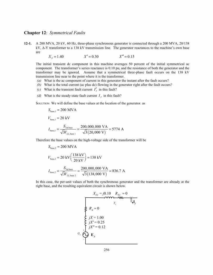
256 Chapter 12: Symmetrical Faults 12-1. A 200 MVA, 20 kV, 60 Hz, three-phase synchronous generator is connected through a 200 MVA, 20/138 kV, Δ-Y transformer to a 138 kV transmission line. The generator reactances to the machine’s own base are 1.40 S X = 0.30 X ′= 0.15 X ′′ = The initial transient dc component in this machine averages 50 percent of the initial symmetrical ac component. The transformer’s series reactance is 0.10 pu, and the resistance of both the generator and the transformer may be ignored. Assume that a symmetrical three-phase fault occurs on the 138 kV transmission line near to the point where it is the transformer. (a) What is the ac component of current in this generator the instant after the fault occurs? (b) What is the total current (ac plus dc) flowing in the generator right after the fault occurs? (c) What is the transient fault current f I ′ in this fault? (d) What is the steady-state fault current f I in this fault? SOLUTION We will define the base values at the location of the generator. as base,1 200 MVA S = base,1 20 kV V = ( ) 3 ,base base,1 ,base 1 200,000,000 VA 5774 A 3 3 20,000 V LL S I V φ = = = Therefore the base values on the high-voltage side of the transformer will be base,2 200 MVA S = base,2 138 kV 20 kV 138 kV 20 kV V = = ( ) 3 ,base base,2 ,base 2 200,000,000 VA 836.7 A 3 3 138,000 V LL S I V φ = = = In this case, the per-unit values of both the synchronous generator and the transformer are already at the right base, and the resulting equivalent circuit is shown below. + - G 1 T 1 I f R A ≈ 0 R T1 ≈ 0 X T1 = j0.10 jX = 1.00 jX' = 0.25 jX" = 0.12 E A
-
Upload
vuongthuan -
Category
Documents
-
view
228 -
download
0
Transcript of ISM to Accompany Electric Machinery and Power System Fundamentals …eebag/Chap 12 solutions.pdf ·...
256
Chapter 12: Symmetrical Faults
12-1. A 200 MVA, 20 kV, 60 Hz, three-phase synchronous generator is connected through a 200 MVA, 20/138
kV, Δ-Y transformer to a 138 kV transmission line. The generator reactances to the machine’s own base
are
1.40SX = 0.30X ′ = 0.15X ′′ =
The initial transient dc component in this machine averages 50 percent of the initial symmetrical ac
component. The transformer’s series reactance is 0.10 pu, and the resistance of both the generator and the
transformer may be ignored. Assume that a symmetrical three-phase fault occurs on the 138 kV
transmission line near to the point where it is the transformer.
(a) What is the ac component of current in this generator the instant after the fault occurs?
(b) What is the total current (ac plus dc) flowing in the generator right after the fault occurs?
(c) What is the transient fault current fI ′ in this fault?
(d) What is the steady-state fault current fI in this fault?
SOLUTION We will define the base values at the location of the generator. as
base,1 200 MVAS =
base,1 20 kVV =
( )
3 ,base
base,1
,base 1
200,000,000 VA5774 A
3 3 20,000 VLL
SI
Vφ= = =
Therefore the base values on the high-voltage side of the transformer will be
base,2 200 MVAS =
base,2
138 kV20 kV 138 kV
20 kVV = =
( )
3 ,base
base,2
,base 2
200,000,000 VA836.7 A
3 3 138,000 VLL
SI
Vφ= = =
In this case, the per-unit values of both the synchronous generator and the transformer are already at the
right base, and the resulting equivalent circuit is shown below.
+
-
G1
T1
If
RA ≈ 0
RT1 ≈ 0XT1 = j0.10
jX = 1.00
jX' = 0.25
jX" = 0.12
EA
257
(a) The per-unit ac fault current immediately after the fault occurs will be the current flowing through the
subtransient reactance X ′′ .
1
1 04.545 90 pu
0.12 0.10
AF
TjX jX j j∠ °= = = ∠ − °′′
+ +′′E
I
The actual ac component of current is ( ) ( )4.545 836.7 A 3803 A=
(b) The total current (ac + dc) right after the fault occurs is ( ) ( )1.5 3803 A 5705 A= .
(c) The per-unit transient fault current will be the current flowing through the transient reactance X ′ .
1
1 02.857 90 pu
0.25 0.10
AF
TjX jX j j∠ °= = = ∠ − °′
+ +′E
I
The actual transient fault current is ( ) ( )2.857 836.7 A 2390 A=
(d) The per-unit steady-state fault current will be the current flowing through the synchronous reactance
SX .
1
1 00.909 90 pu
1.00 0.10
AF
S TjX jX j j∠ °= = = ∠ − °
+ +E
I
The actual steady-state fault current is ( ) ( )0.909 836.7 A 761 A=
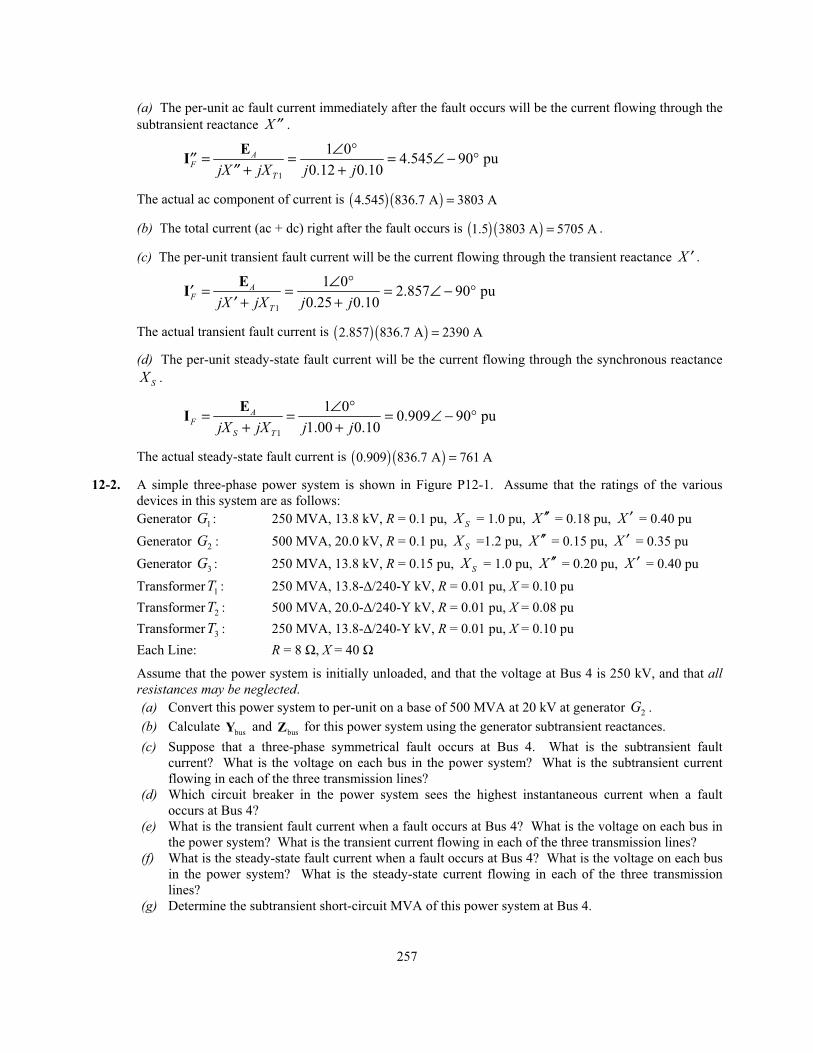
12-2. A simple three-phase power system is shown in Figure P12-1. Assume that the ratings of the various
devices in this system are as follows:
Generator 1G : 250 MVA, 13.8 kV, R = 0.1 pu, SX = 1.0 pu, X ′′ = 0.18 pu, X ′ = 0.40 pu
Generator 2G : 500 MVA, 20.0 kV, R = 0.1 pu, SX =1.2 pu, X ′′ = 0.15 pu, X ′ = 0.35 pu
Generator 3G : 250 MVA, 13.8 kV, R = 0.15 pu, SX = 1.0 pu, X ′′ = 0.20 pu, X ′ = 0.40 pu
Transformer 1T : 250 MVA, 13.8-Δ/240-Y kV, R = 0.01 pu, X = 0.10 pu
Transformer 2T : 500 MVA, 20.0-Δ/240-Y kV, R = 0.01 pu, X = 0.08 pu
Transformer 3T : 250 MVA, 13.8-Δ/240-Y kV, R = 0.01 pu, X = 0.10 pu
Each Line: R = 8 Ω, X = 40 Ω
Assume that the power system is initially unloaded, and that the voltage at Bus 4 is 250 kV, and that allresistances may be neglected.
(a) Convert this power system to per-unit on a base of 500 MVA at 20 kV at generator 2G .
(b) Calculate busY and
busZ for this power system using the generator subtransient reactances.
(c) Suppose that a three-phase symmetrical fault occurs at Bus 4. What is the subtransient fault
current? What is the voltage on each bus in the power system? What is the subtransient current
flowing in each of the three transmission lines?
(d) Which circuit breaker in the power system sees the highest instantaneous current when a fault
occurs at Bus 4?
(e) What is the transient fault current when a fault occurs at Bus 4? What is the voltage on each bus in
the power system? What is the transient current flowing in each of the three transmission lines?
(f) What is the steady-state fault current when a fault occurs at Bus 4? What is the voltage on each bus
in the power system? What is the steady-state current flowing in each of the three transmission
lines?
(g) Determine the subtransient short-circuit MVA of this power system at Bus 4.
258
1 23
4
G3
T3
G2
T2
G1
T1
Region 1 Region 2 Region 3
Region 4
Figure P12-1 The simple power system of Problem 12-2.
SOLUTION The base quantities for this power system are 500 MVA at 20 kV at generator 2G , which is in
Region 3. Therefore, the base quantities are:
base,3 500 MVAS =
base,3 20 kVV =
( )
3 ,base
base,3
,base 3
500,000,000 VA14,430 A
3 3 20,000 VLL
SI
Vφ= = =
( ) ( )
2 2
,base 3
base,3
3 ,base
20,000 V0.80
500,000,000 VA
LLVZ
S φ
= = = Ω
base,2 500 MVAS =
base,2
240 kV20 kV 240 kV
20 kVV = =
( )
3 ,base
base,2
,base 2
500,000,000 VA1203 A
3 3 240,000 VLL
SI
Vφ= = =
( ) ( )
2 2
,base 2
base,2
3 ,base
240,000 V115.2
500,000,000 VA
LLVZ
S φ
= = = Ω
base,1 500 MVAS =
base,1
13.8 kV240 kV 13.8 kV
240 kVV = =
259
( )
3 ,base
base,1
,base 1
500,000,000 VA20,910 A
3 3 13,800 VLL
SI
Vφ= = =
( ) ( )
2 2
,base 1
base,1
3 ,base
13,800 V0.381
500,000,000 VA
LLVZ
S φ
= = = Ω
base,4 500 MVAS =
base,4
13.8 kV240 kV 13.8 kV
240 kVV = =
( )
3 ,base
base,4
,base 4
500,000,000 VA20,910 A
3 3 13,800 VLL
SI
Vφ= = =
( ) ( )
2 2
,base 4
base,4
3 ,base
13,800 V0.381
500,000,000 VA
LLVZ
S φ
= = = Ω
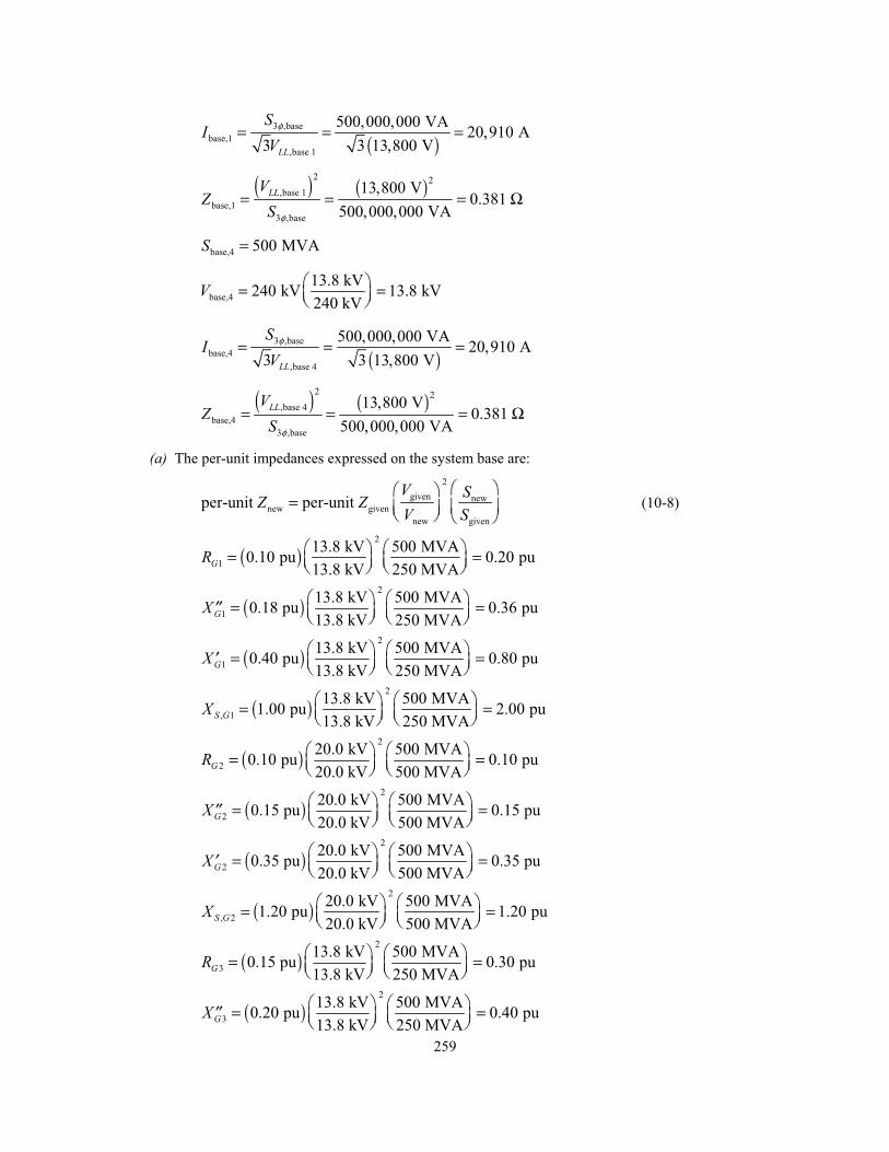
(a) The per-unit impedances expressed on the system base are:
2
given newnew given
new given
per-unit per-unit V SZ ZV S
= (10-8)
( )2
1
13.8 kV 500 MVA0.10 pu 0.20 pu
13.8 kV 250 MVAGR = =
( )2
1
13.8 kV 500 MVA0.18 pu 0.36 pu
13.8 kV 250 MVAGX = =′′
( )2
1
13.8 kV 500 MVA0.40 pu 0.80 pu
13.8 kV 250 MVAGX = =′
( )2
, 1
13.8 kV 500 MVA1.00 pu 2.00 pu
13.8 kV 250 MVAS GX = =
( )2
2
20.0 kV 500 MVA0.10 pu 0.10 pu
20.0 kV 500 MVAGR = =
( )2
2
20.0 kV 500 MVA0.15 pu 0.15 pu
20.0 kV 500 MVAGX = =′′
( )2
2
20.0 kV 500 MVA0.35 pu 0.35 pu
20.0 kV 500 MVAGX = =′
( )2
, 2
20.0 kV 500 MVA1.20 pu 1.20 pu
20.0 kV 500 MVAS GX = =
( )2
3
13.8 kV 500 MVA0.15 pu 0.30 pu
13.8 kV 250 MVAGR = =
( )2
3
13.8 kV 500 MVA0.20 pu 0.40 pu
13.8 kV 250 MVAGX = =′′
260
( )2
3
13.8 kV 500 MVA0.40 pu 0.80 pu
13.8 kV 250 MVAGX = =′
( )2
, 3
13.8 kV 500 MVA1.00 pu 2.00 pu
13.8 kV 250 MVAS GX = =
( )2
1
13.8 kV 500 MVA0.01 pu 0.02 pu
13.8 kV 250 MVATR = =
( )2
1
13.8 kV 500 MVA0.10 pu 0.20 pu
13.8 kV 250 MVATX = =
( )2
2
20.0 kV 500 MVA0.01 pu 0.01 pu
20.0 kV 500 MVATR = =
( )2
2
20.0 kV 500 MVA0.08 pu 0.08 pu
20.0 kV 500 MVATX = =
( )2
3
13.8 kV 500 MVA0.01 pu 0.02 pu
13.8 kV 250 MVATR = =
( )2
3
13.8 kV 500 MVA0.10 pu 0.20 pu
13.8 kV 250 MVATX = =
line,
line,pu
base
80.0694 pu
115.2
RR
ZΩ Ω= = =
Ω
line,
line,pu
base
40 0.3472 pu
115.2
XX
ZΩ Ω= = =
Ω
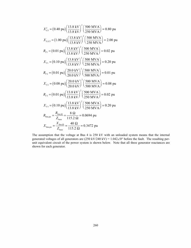
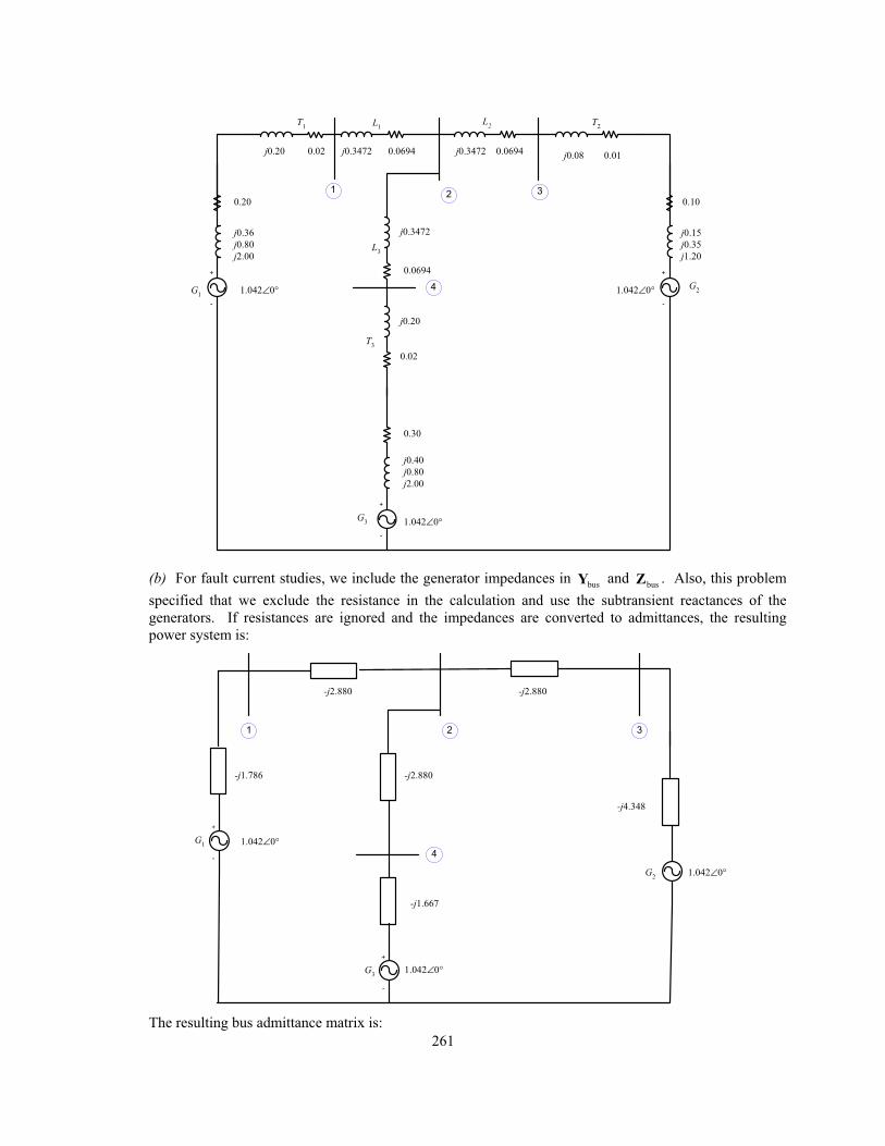
The assumption that the voltage at Bus 4 is 250 kV with an unloaded system means that the internal
generated voltages of all generators are (250 kV/240 kV) = 1.042∠0° before the fault. The resulting per-
unit equivalent circuit of the power system is shown below. Note that all three generator reactances are
shown for each generator.
261
+
-
G1
0.20
j0.36
j0.80
j2.00
L1
T1
j0.3472
0.30
T2
+
-
G2
0.10
j0.15
j0.35
j1.20L
3
+
-
G3
T3
0.0694
L2
j0.3472
j0.3472 0.06940.06940.02
j0.40
j0.80
j2.00
j0.20 j0.08 0.01
1.042∠0°
1.042∠0°
1.042∠0°
1
4
32
0.02
j0.20
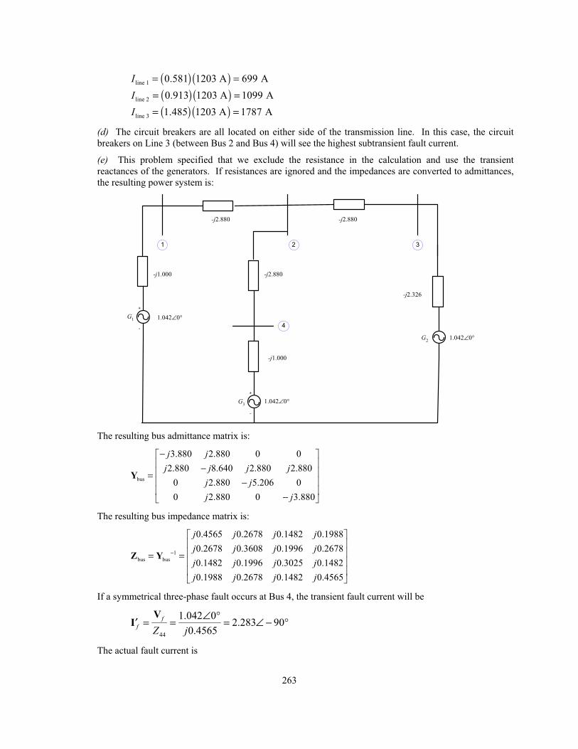
(b) For fault current studies, we include the generator impedances in busY and
busZ . Also, this problem
specified that we exclude the resistance in the calculation and use the subtransient reactances of the
generators. If resistances are ignored and the impedances are converted to admittances, the resulting
power system is:
+
-
G3
-j1.786
1.042∠0°
1.042∠0°
1
4
32
+
-
G1
G2
1.042∠0°
-j2.880
-j2.880
-j1.667
-j4.348
-j2.880
The resulting bus admittance matrix is:
262
bus
4.666 2.880 0 0
2.880 8.640 2.880 2.880
0 2.880 7.228 0
0 2.880 0 4.547
j jj j j j
j jj j
−−
=−
−
Y
The resulting bus impedance matrix is:
1
bus bus
0.3128 0.1589 0.0633 0.1007
0.1589 0.2572 0.1025 0.1629
0.0633 0.1025 0.1792 0.0649
0.1007 0.1629 0.0649 0.3231
j j j jj j j jj j j jj j j j
−= =Z Y
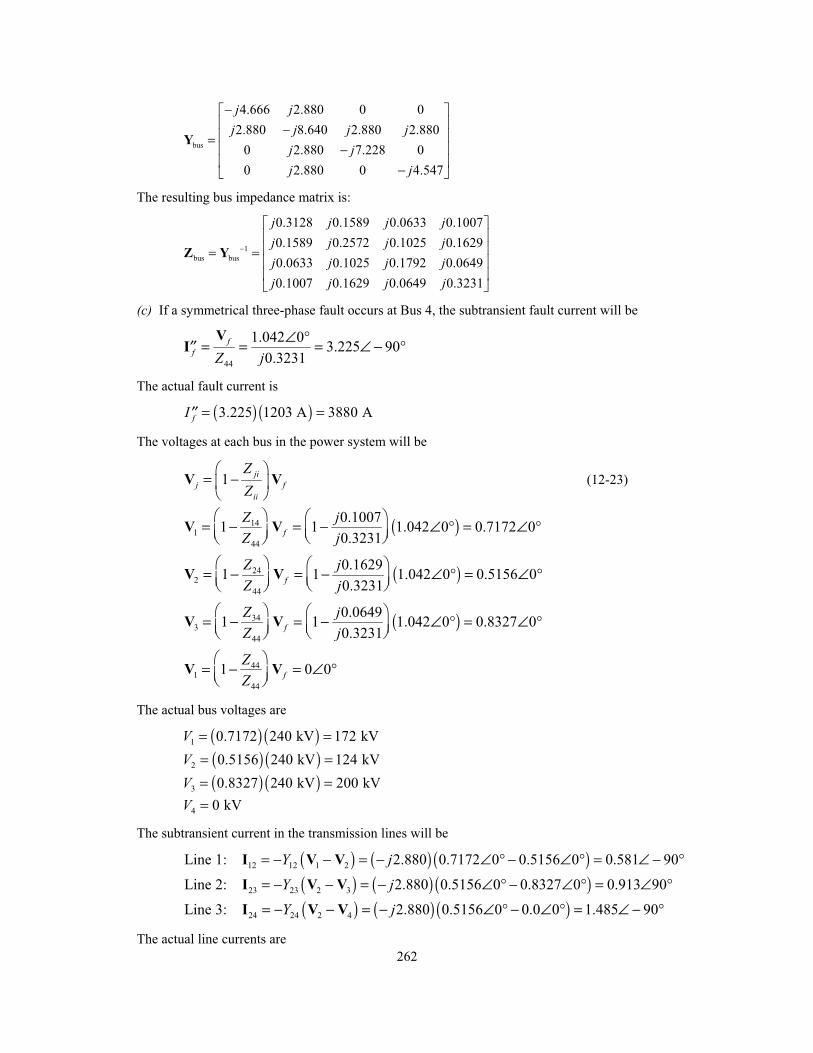
(c) If a symmetrical three-phase fault occurs at Bus 4, the subtransient fault current will be
44
1.042 03.225 90
0.3231
ff Z j
∠ °= = = ∠ − °′′V
I
The actual fault current is
( ) ( )3.225 1203 A 3880 AfI = =′′
The voltages at each bus in the power system will be
1ji
j fii
ZZ
= −V V (12-23)
( )141
44
0.10071 1 1.042 0 0.7172 0
0.3231f
Z jZ j
= − = − ∠ ° = ∠ °V V
( )242
44
0.16291 1 1.042 0 0.5156 0
0.3231f
Z jZ j
= − = − ∠ ° = ∠ °V V
( )343
44
0.06491 1 1.042 0 0.8327 0
0.3231f
Z jZ j
= − = − ∠ ° = ∠ °V V
441
44
1 0 0fZZ
= − = ∠ °V V
The actual bus voltages are
( ) ( )1 0.7172 240 kV 172 kVV = = ( ) ( )2 0.5156 240 kV 124 kVV = = ( ) ( )3 0.8327 240 kV 200 kVV = =
4 0 kVV =
The subtransient current in the transmission lines will be
( ) ( ) ( )12 12 1 2Line 1: 2.880 0.7172 0 0.5156 0 0.581 90Y j= − − = − ∠ ° − ∠ ° = ∠ − °I V V
( ) ( ) ( )23 23 2 3Line 2: 2.880 0.5156 0 0.8327 0 0.913 90Y j= − − = − ∠ ° − ∠ ° = ∠ °I V V
( ) ( ) ( )24 24 2 4Line 3: 2.880 0.5156 0 0.0 0 1.485 90Y j= − − = − ∠ ° − ∠ ° = ∠ − °I V V
The actual line currents are
263
( ) ( )line 1 0.581 1203 A 699 AI = = ( ) ( )line 2 0.913 1203 A 1099 AI = = ( ) ( )line 3 1.485 1203 A 1787 AI = =
(d) The circuit breakers are all located on either side of the transmission line. In this case, the circuit
breakers on Line 3 (between Bus 2 and Bus 4) will see the highest subtransient fault current.
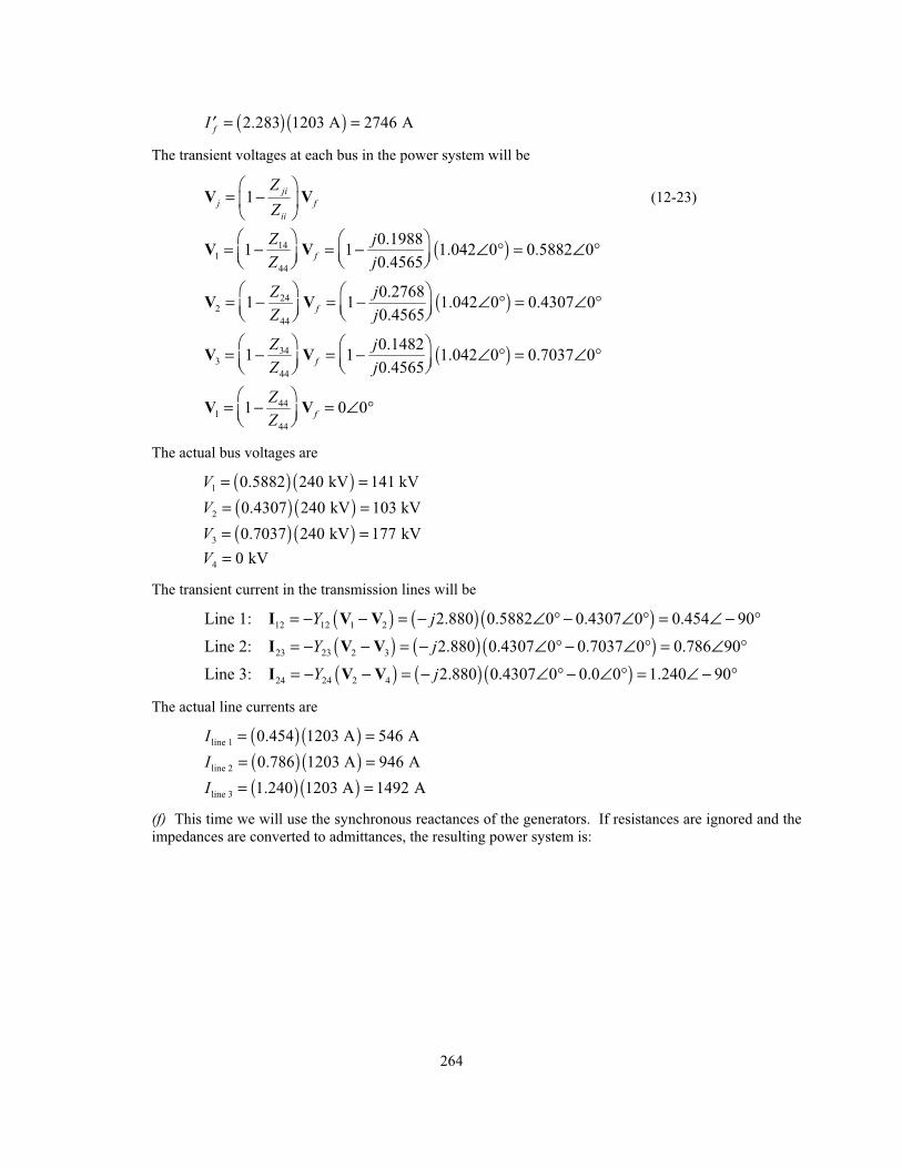
(e) This problem specified that we exclude the resistance in the calculation and use the transient
reactances of the generators. If resistances are ignored and the impedances are converted to admittances,
the resulting power system is:
+
-
G3
-j1.000
1.042∠0°
1.042∠0°
1
4
32
+
-
G1
G2
1.042∠0°
-j2.880
-j2.880
-j1.000
-j2.326
-j2.880
The resulting bus admittance matrix is:
bus
3.880 2.880 0 0
2.880 8.640 2.880 2.880
0 2.880 5.206 0
0 2.880 0 3.880
j jj j j j
j jj j
−−
=−
−
Y
The resulting bus impedance matrix is:
1
bus bus
0.4565 0.2678 0.1482 0.1988
0.2678 0.3608 0.1996 0.2678
0.1482 0.1996 0.3025 0.1482
0.1988 0.2678 0.1482 0.4565
j j j jj j j jj j j jj j j j
−= =Z Y
If a symmetrical three-phase fault occurs at Bus 4, the transient fault current will be
44
1.042 02.283 90
0.4565
ff Z j
∠ °= = = ∠ − °′V
I
The actual fault current is
264
( ) ( )2.283 1203 A 2746 AfI = =′
The transient voltages at each bus in the power system will be
1ji
j fii
ZZ
= −V V (12-23)
( )141
44
0.19881 1 1.042 0 0.5882 0
0.4565f
Z jZ j
= − = − ∠ ° = ∠ °V V
( )242
44
0.27681 1 1.042 0 0.4307 0
0.4565f
Z jZ j
= − = − ∠ ° = ∠ °V V
( )343
44
0.14821 1 1.042 0 0.7037 0
0.4565f
Z jZ j
= − = − ∠ ° = ∠ °V V
441
44
1 0 0fZZ
= − = ∠ °V V
The actual bus voltages are
( ) ( )1 0.5882 240 kV 141 kVV = = ( ) ( )2 0.4307 240 kV 103 kVV = = ( ) ( )3 0.7037 240 kV 177 kVV = =
4 0 kVV =
The transient current in the transmission lines will be
( ) ( ) ( )12 12 1 2Line 1: 2.880 0.5882 0 0.4307 0 0.454 90Y j= − − = − ∠ ° − ∠ ° = ∠ − °I V V
( ) ( ) ( )23 23 2 3Line 2: 2.880 0.4307 0 0.7037 0 0.786 90Y j= − − = − ∠ ° − ∠ ° = ∠ °I V V
( ) ( ) ( )24 24 2 4Line 3: 2.880 0.4307 0 0.0 0 1.240 90Y j= − − = − ∠ ° − ∠ ° = ∠ − °I V V
The actual line currents are
( ) ( )line 1 0.454 1203 A 546 AI = = ( ) ( )line 2 0.786 1203 A 946 AI = = ( ) ( )line 3 1.240 1203 A 1492 AI = =
(f) This time we will use the synchronous reactances of the generators. If resistances are ignored and the
impedances are converted to admittances, the resulting power system is:
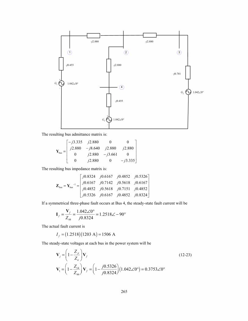
265
+
-
G3
-j0.455
1.042∠0°
1.042∠0°
1
4
32
+
-
G1
G2
1.042∠0°
-j2.880
-j2.880
-j0.455
-j0.781
-j2.880
The resulting bus admittance matrix is:
bus
3.335 2.880 0 0
2.880 8.640 2.880 2.880
0 2.880 3.661 0
0 2.880 0 3.335
j jj j j j
j jj j
−−
=−
−
Y
The resulting bus impedance matrix is:
1
bus bus
0.8324 0.6167 0.4852 0.5326
0.6167 0.7142 0.5618 0.6167
0.4852 0.5618 0.7151 0.4852
0.5326 0.6167 0.4852 0.8324
j j j jj j j jj j j jj j j j
−= =Z Y
If a symmetrical three-phase fault occurs at Bus 4, the steady-state fault current will be
44
1.042 01.2518 90
0.8324
ff Z j
∠ °= = = ∠ − °V
I
The actual fault current is
( ) ( )1.2518 1203 A 1506 AfI = =
The steady-state voltages at each bus in the power system will be
1ji
j fii
ZZ
= −V V (12-23)
( )141
44
0.53261 1 1.042 0 0.3753 0
0.8324f
Z jZ j
= − = − ∠ ° = ∠ °V V
266
( )242
44
0.61671 1 1.042 0 0.2700 0
0.8324f
Z jZ j
= − = − ∠ ° = ∠ °V V
( )343
44
0.48521 1 1.042 0 0.4346 0
0.8324f
Z jZ j
= − = − ∠ ° = ∠ °V V
441
44
1 0 0fZZ
= − = ∠ °V V
The actual bus voltages are
( ) ( )1 0.3753 240 kV 90 kVV = = ( ) ( )2 0.2700 240 kV 65 kVV = = ( ) ( )3 0.4346 240 kV 104 kVV = =
4 0 kVV =
The steady-state current in the transmission lines will be
( ) ( ) ( )12 12 1 2Line 1: 2.880 0.3753 0 0.2700 0 0.303 90Y j= − − = − ∠ ° − ∠ ° = ∠ − °I V V
( ) ( ) ( )23 23 2 3Line 2: 2.880 0.2700 0 0.4346 0 0.474 90Y j= − − = − ∠ ° − ∠ ° = ∠ °I V V
( ) ( ) ( )24 24 2 4Line 3: 2.880 0.2700 0 0.0 0 0.778 90Y j= − − = − ∠ ° − ∠ ° = ∠ − °I V V
The actual line currents are
( ) ( )line 1 0.303 1203 A 365 AI = = ( ) ( )line 2 0.474 1203 A 570 AI = = ( ) ( )line 3 0.778 1203 A 936 AI = =
(g) The per-unit short-circuit MVA at Bus 4 is just equal to the per-unit fault current at that bus.
pu ,puShort-circuit MVA 2.283SCI= =
Therefore, the subtransient short-circuit MVA at Bus 4 is
( ) ( )pu baseShort-circuit MVA Short-circuit MVA S=
( ) ( )Short-circuit MVA 2.283 500 MVA 1142 MVA= =
Note: This problem could also be solved using program faults, it we treat the terminals of each
generator as an additional bus. The input file for this power system is shown below.
% File describing the power system of Problem 12-2.%% System data has the form:%SYSTEM name baseMVASYSTEM Prob12_2 500%% Bus data has the form:%BUS name voltsBUS One 1.042BUS Two 1.042BUS Three 1.042
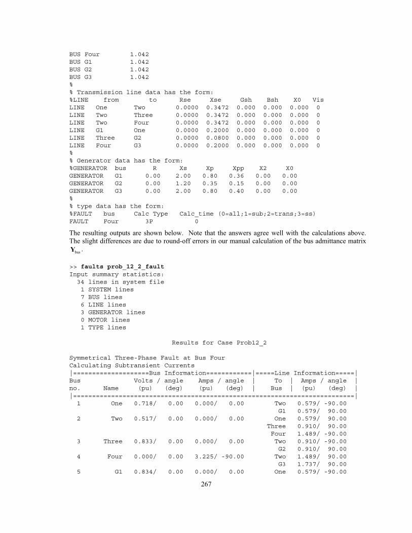
267
BUS Four 1.042BUS G1 1.042BUS G2 1.042BUS G3 1.042%% Transmission line data has the form:%LINE from to Rse Xse Gsh Bsh X0 VisLINE One Two 0.0000 0.3472 0.000 0.000 0.000 0LINE Two Three 0.0000 0.3472 0.000 0.000 0.000 0LINE Two Four 0.0000 0.3472 0.000 0.000 0.000 0LINE G1 One 0.0000 0.2000 0.000 0.000 0.000 0LINE Three G2 0.0000 0.0800 0.000 0.000 0.000 0LINE Four G3 0.0000 0.2000 0.000 0.000 0.000 0%% Generator data has the form:%GENERATOR bus R Xs Xp Xpp X2 X0GENERATOR G1 0.00 2.00 0.80 0.36 0.00 0.00GENERATOR G2 0.00 1.20 0.35 0.15 0.00 0.00GENERATOR G3 0.00 2.00 0.80 0.40 0.00 0.00%% type data has the form:%FAULT bus Calc Type Calc_time (0=all;1=sub;2=trans;3=ss)FAULT Four 3P 0
The resulting outputs are shown below. Note that the answers agree well with the calculations above.
The slight differences are due to round-off errors in our manual calculation of the bus admittance matrix
busY .
>> faults prob_12_2_faultInput summary statistics:34 lines in system file1 SYSTEM lines7 BUS lines6 LINE lines3 GENERATOR lines0 MOTOR lines1 TYPE lines
Results for Case Prob12_2
Symmetrical Three-Phase Fault at Bus FourCalculating Subtransient Currents|====================Bus Information============|=====Line Information=====|Bus Volts / angle Amps / angle | To | Amps / angle |no. Name (pu) (deg) (pu) (deg) | Bus | (pu) (deg) ||==========================================================================|1 One 0.718/ 0.00 0.000/ 0.00 Two 0.579/ -90.00
G1 0.579/ 90.002 Two 0.517/ 0.00 0.000/ 0.00 One 0.579/ 90.00
Three 0.910/ 90.00Four 1.489/ -90.00
3 Three 0.833/ 0.00 0.000/ 0.00 Two 0.910/ -90.00G2 0.910/ 90.00
4 Four 0.000/ 0.00 3.225/ -90.00 Two 1.489/ 90.00G3 1.737/ 90.00
5 G1 0.834/ 0.00 0.000/ 0.00 One 0.579/ -90.00
268
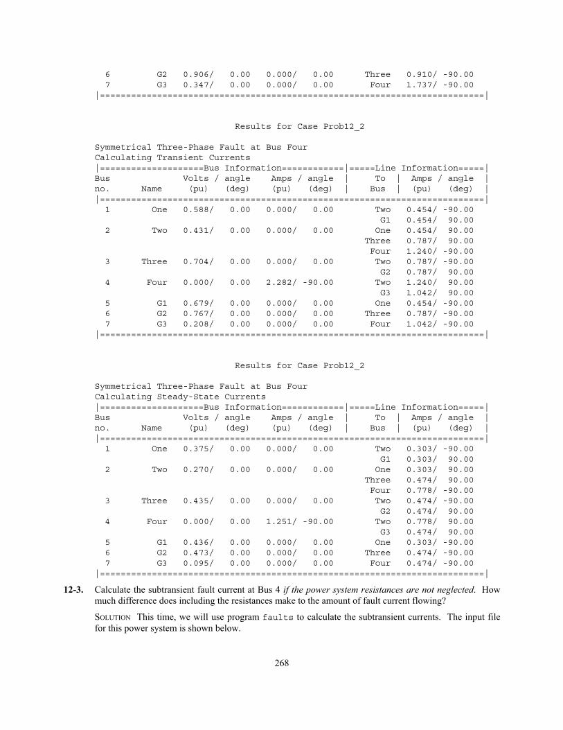
6 G2 0.906/ 0.00 0.000/ 0.00 Three 0.910/ -90.007 G3 0.347/ 0.00 0.000/ 0.00 Four 1.737/ -90.00
|==========================================================================|
Results for Case Prob12_2
Symmetrical Three-Phase Fault at Bus FourCalculating Transient Currents|====================Bus Information============|=====Line Information=====|Bus Volts / angle Amps / angle | To | Amps / angle |no. Name (pu) (deg) (pu) (deg) | Bus | (pu) (deg) ||==========================================================================|1 One 0.588/ 0.00 0.000/ 0.00 Two 0.454/ -90.00
G1 0.454/ 90.002 Two 0.431/ 0.00 0.000/ 0.00 One 0.454/ 90.00
Three 0.787/ 90.00Four 1.240/ -90.00
3 Three 0.704/ 0.00 0.000/ 0.00 Two 0.787/ -90.00G2 0.787/ 90.00
4 Four 0.000/ 0.00 2.282/ -90.00 Two 1.240/ 90.00G3 1.042/ 90.00
5 G1 0.679/ 0.00 0.000/ 0.00 One 0.454/ -90.006 G2 0.767/ 0.00 0.000/ 0.00 Three 0.787/ -90.007 G3 0.208/ 0.00 0.000/ 0.00 Four 1.042/ -90.00
|==========================================================================|
Results for Case Prob12_2
Symmetrical Three-Phase Fault at Bus FourCalculating Steady-State Currents|====================Bus Information============|=====Line Information=====|Bus Volts / angle Amps / angle | To | Amps / angle |no. Name (pu) (deg) (pu) (deg) | Bus | (pu) (deg) ||==========================================================================|1 One 0.375/ 0.00 0.000/ 0.00 Two 0.303/ -90.00
G1 0.303/ 90.002 Two 0.270/ 0.00 0.000/ 0.00 One 0.303/ 90.00
Three 0.474/ 90.00Four 0.778/ -90.00
3 Three 0.435/ 0.00 0.000/ 0.00 Two 0.474/ -90.00G2 0.474/ 90.00
4 Four 0.000/ 0.00 1.251/ -90.00 Two 0.778/ 90.00G3 0.474/ 90.00
5 G1 0.436/ 0.00 0.000/ 0.00 One 0.303/ -90.006 G2 0.473/ 0.00 0.000/ 0.00 Three 0.474/ -90.007 G3 0.095/ 0.00 0.000/ 0.00 Four 0.474/ -90.00
|==========================================================================|
12-3. Calculate the subtransient fault current at Bus 4 if the power system resistances are not neglected. How
much difference does including the resistances make to the amount of fault current flowing?
SOLUTION This time, we will use program faults to calculate the subtransient currents. The input file
for this power system is shown below.
269
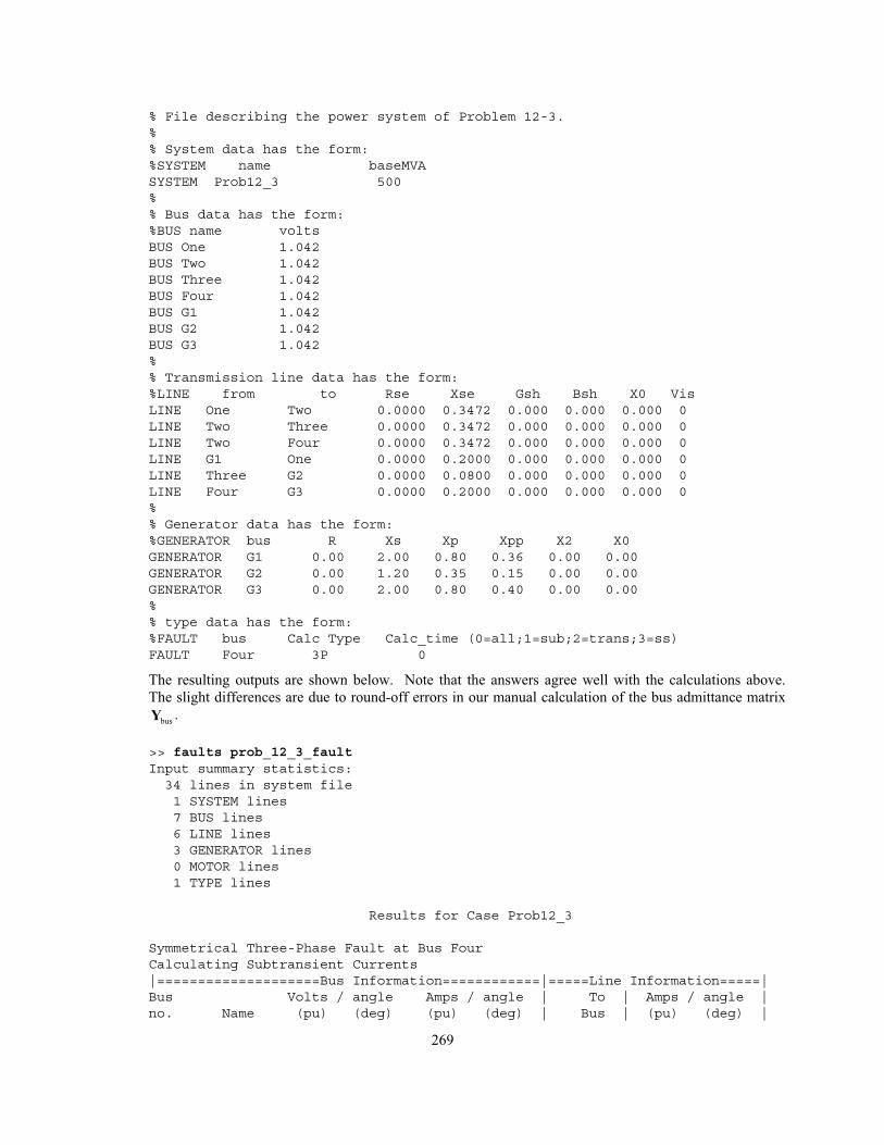
% File describing the power system of Problem 12-3.%% System data has the form:%SYSTEM name baseMVASYSTEM Prob12_3 500%% Bus data has the form:%BUS name voltsBUS One 1.042BUS Two 1.042BUS Three 1.042BUS Four 1.042BUS G1 1.042BUS G2 1.042BUS G3 1.042%% Transmission line data has the form:%LINE from to Rse Xse Gsh Bsh X0 VisLINE One Two 0.0000 0.3472 0.000 0.000 0.000 0LINE Two Three 0.0000 0.3472 0.000 0.000 0.000 0LINE Two Four 0.0000 0.3472 0.000 0.000 0.000 0LINE G1 One 0.0000 0.2000 0.000 0.000 0.000 0LINE Three G2 0.0000 0.0800 0.000 0.000 0.000 0LINE Four G3 0.0000 0.2000 0.000 0.000 0.000 0%% Generator data has the form:%GENERATOR bus R Xs Xp Xpp X2 X0GENERATOR G1 0.00 2.00 0.80 0.36 0.00 0.00GENERATOR G2 0.00 1.20 0.35 0.15 0.00 0.00GENERATOR G3 0.00 2.00 0.80 0.40 0.00 0.00%% type data has the form:%FAULT bus Calc Type Calc_time (0=all;1=sub;2=trans;3=ss)FAULT Four 3P 0
The resulting outputs are shown below. Note that the answers agree well with the calculations above.
The slight differences are due to round-off errors in our manual calculation of the bus admittance matrix
busY .
>> faults prob_12_3_faultInput summary statistics:34 lines in system file1 SYSTEM lines7 BUS lines6 LINE lines3 GENERATOR lines0 MOTOR lines1 TYPE lines
Results for Case Prob12_3
Symmetrical Three-Phase Fault at Bus FourCalculating Subtransient Currents|====================Bus Information============|=====Line Information=====|Bus Volts / angle Amps / angle | To | Amps / angle |no. Name (pu) (deg) (pu) (deg) | Bus | (pu) (deg) |
270
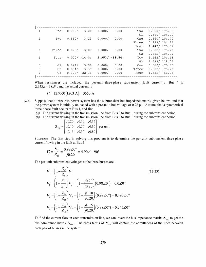
|==========================================================================|1 One 0.709/ 3.20 0.000/ 0.00 Two 0.560/ -75.30
G1 0.560/ 104.702 Two 0.510/ 3.13 0.000/ 0.00 One 0.560/ 104.70
Three 0.882/ 104.27Four 1.442/ -75.57
3 Three 0.823/ 3.07 0.000/ 0.00 Two 0.882/ -75.73G2 0.882/ 104.27
4 Four 0.000/ -14.04 2.953/ -68.54 Two 1.442/ 104.43G3 1.532/ 118.07
5 G1 0.821/ 3.99 0.000/ 0.00 One 0.560/ -75.306 G2 0.894/ 3.39 0.000/ 0.00 Three 0.882/ -75.737 G3 0.308/ 22.36 0.000/ 0.00 Four 1.532/ -61.93
|==========================================================================|
When resistances are included, the per-unit three-phase subtransient fault current at Bus 4 is
2.953 68.5∠ − ° , and the actual current is
( ) ( )2.953 1203 A 3553 AfI = =′′
12-4. Suppose that a three-bus power system has the subtransient bus impedance matrix given below, and that
the power system is initially unloaded with a pre-fault bus voltage of 0.98 pu. Assume that a symmetrical
three-phase fault occurs at Bus 1, and find:
(a) The current flowing in the transmission line from Bus 2 to Bus 1 during the subtransient period.
(b) The current flowing in the transmission line from Bus 3 to Bus 1 during the subtransient period.
bus
0.20 0.10 0.15
0.10 0.50 0.30 per unit
0.15 0.30 0.80
j j jj j jj j j
=Z
SOLUTION The first step in solving this problem is to determine the per-unit subtransient three-phase
current flowing in the fault at Bus 1.
44
0.98 04.90 90
0.20
ff Z j
∠ °= = = ∠ − °′′V
I
The per-unit subtransient voltages at the three busses are:
1ji
j fii
ZZ
= −V V (12-23)
( )111
11
0.201 1 0.98 0 0.0 0
0.20f
Z jZ j
= − = − ∠ ° = ∠ °V V
( )212
11
0.101 1 0.98 0 0.490 0
0.20f
Z jZ j
= − = − ∠ ° = ∠ °V V
( )213
11
0.151 1 0.98 0 0.245 0
0.20f
Z jZ j
= − = − ∠ ° = ∠ °V V
To find the current flow in each transmission line, we can invert the bus impedance matrix busZ to get the
bus admittance matrix busY . The cross terms of
busY will contain the admittances of the lines between
each pair of busses in the system.
271
1
bus bus
5.9903 0.6763 0.8696
0.6763 2.6570 0.8696 per unit
0.8696 0.8696 1.7391
j j jj j jj j j
−
−= = −
−Y Z
( ) ( ) ( )21 21 2 1 0.6763 0.490 0 0.0 0 0.3314 90Y j= − − = − ∠ ° − ∠ ° = ∠ − °I V V
( ) ( ) ( )31 31 3 1 0.8696 0.245 0 0.0 0 0.2131 90Y j= − − = − ∠ ° − ∠ ° = ∠ − °I V V
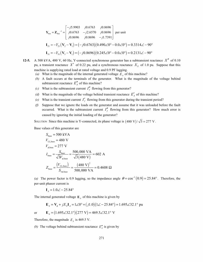
12-5. A 500 kVA, 480 V, 60 Hz, Y-connected synchronous generator has a subtransient reactance X ′′ of 0.10
pu, a transient reactance X ′ of 0.22 pu, and a synchronous reactance SX of 1.0 pu. Suppose that this
machine is supplying rated load at rated voltage and 0.9 PF lagging.
(a) What is the magnitude of the internal generated voltage AE of this machine?
(b) A fault occurs at the terminals of the generator. What is the magnitude of the voltage behind
subtransient reactance AE′′ of this machine?
(c) What is the subtransient current fI ′′ flowing from this generator?
(d) What is the magnitude of the voltage behind transient reactance AE′ of this machine?
(e) What is the transient current fI ′ flowing from this generator during the transient period?
(f) Suppose that we ignore the loads on the generator and assume that it was unloaded before the fault
occurred. What is the subtransient current fI ′′ flowing from this generator? How much error is
caused by ignoring the initial loading of the generator?
SOLUTION Since this machine is Y-connected, its phase voltage is ( )480 V / 3 277 V= .
Base values of this generator are
base 500 kVAS = LL,base 480 VV = ,base 277 VVφ =
( )
basebase
,base
500,000 VA602 A
3 3 480 V
SIVφ
= = =
( ) ( )2
LL,base
base
3 ,base
480 V0.4608
500,000 VA
VZ
S φ
= = = Ω
(a) The power factor is 0.9 lagging, so the impedance angle ( )1cos 0.9 25.84θ −= = ° . Therefore, the
per-unit phasor current is
1.0 25.84A = ∠ − °I
The internal generated voltage AE of this machine is given by
( ) ( )1 0 1.0 1 25.84 1.695 32.1 puA S AjX jφ= + = ∠ ° + ∠ − ° = ∠ °E V I
or ( ) ( )1.695 32.1 277 V 469.5 32.1 VA = ∠ ° = ∠ °E
Therefore, the magnitude AE is 469.5 V.
(b) The voltage behind subtransient reactance AE′′ is given by
272
( ) ( )1 0 0.10 1 25.84 1.048 4.9 puA AjX jφ= + = ∠ ° + ∠ − ° = ∠ °′′ ′′E V I
or ( ) ( )1.048 4.9 277 V 290 4.9 VA = ∠ ° = ∠ °′′E
(c) The per-unit subtransient fault current fI ′′ is given by
1.048 4.9
10.48 85.1 pu0.10
Af jX j
∠ °′′= = = ∠ − °′′′′
EI
Therefore, the actual subtransient fault current is ( ) ( )10.48 pu 602 A 6309 AfI = =′′ .
(d) The voltage behind transient reactance A′E is given by
( ) ( )1 0 0.22 1 25.84 1.136 10.2 puA AjX jφ= + = ∠ ° + ∠ − ° = ∠ °′ ′E V I
or ( ) ( )1.136 10.2 277 V 315 10.2 VA = ∠ ° = ∠ °′′E
(e) The per-unit subtransient fault current fI ′′ is given by
1.136 10.2
5.164 79.8 pu0.22
Af jX j
∠ °′= = = ∠ − °′′
EI
Therefore, the actual subtransient fault current is ( ) ( )5.164 pu 602 A 3109 AfI = =′′ .
(f) If we assume that the generator was initially unloaded before the fault, the per-unit subtransient fault
current fI ′′ is given by
1.00 0
10.0 90 pu0.10
Af jX j
∠ °′′= = = ∠ − °′′′′
EI
The error caused by ignoring the initial loads is (10.48 – 10) / 10 × 100% = 4.8%.
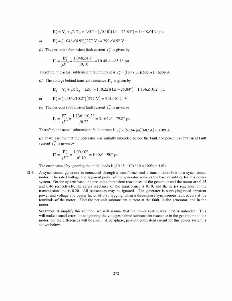
12-6. A synchronous generator is connected through a transformer and a transmission line to a synchronous
motor. The rated voltage and apparent power of the generator serve as the base quantities for this power
system. On the system base, the per unit subtransient reactances of the generator and the motor are 0.15
and 0.40 respectively, the series reactance of the transformer is 0.10, and the series reactance of the
transmission line is 0.20. All resistances may be ignored. The generator is supplying rated apparent
power and voltage at a power factor of 0.85 lagging, when a three-phase synchronous fault occurs at the
terminals of the motor. Find the per-unit subtransient current at the fault, in the generator, and in the
motor.
SOLUTION It simplify this solution, we will assume that the power system was initially unloaded. This
will make a small error due to ignoring the voltages behind subtransient reactance in the generator and the
motor, but the differences will be small. A per-phase, per-unit equivalent circuit for this power system is
shown below.
273
+
-
G1
L1
T1
M2
j0.20j0.10
j0.40
1.00∠0° 1.00∠0°
1 2
j0.15
+
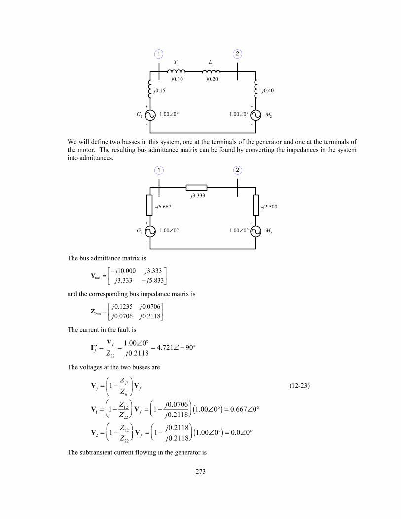
-
We will define two busses in this system, one at the terminals of the generator and one at the terminals of
the motor. The resulting bus admittance matrix can be found by converting the impedances in the system
into admittances.
+
-
G1
M2
-j3.333
-j2.500
1.00∠0° 1.00∠0°
1 2
-j6.667
+
-
The bus admittance matrix is
bus
10.000 3.333
3.333 5.833
j jj j
−=
−Y
and the corresponding bus impedance matrix is
bus
0.1235 0.0706
0.0706 0.2118
j jj j
=Z
The current in the fault is
22
1.00 04.721 90
0.2118
ff Z j
∠ °= = = ∠ − °′′V
I
The voltages at the two busses are
1ji
j fii
ZZ
= −V V (12-23)
( )121
22
0.07061 1 1.00 0 0.667 0
0.2118f
Z jZ j
= − = − ∠ ° = ∠ °V V
( )222
22
0.21181 1 1.00 0 0.0 0
0.2118f
Z jZ j
= − = − ∠ ° = ∠ °V V
The subtransient current flowing in the generator is
274
, 1.00 0 0.667 0
2.222 900.15
A GG
GjX jφ− ∠ ° − ∠ °= = = ∠ − °′′
′′E V
I
The subtransient current flowing in the motor is
, 1.00 0 0.0 0
2.500 900.40
A MM
MjX jφ− ∠ ° − ∠ °= = = ∠ − °′′
′′E V
I
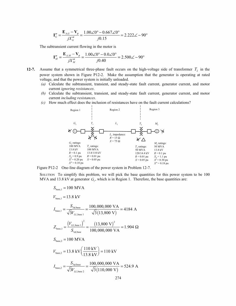
12-7. Assume that a symmetrical three-phase fault occurs on the high-voltage side of transformer 2T in the
power system shown in Figure P12-2. Make the assumption that the generator is operating at rated
voltage, and that the power system is initially unloaded.
(a) Calculate the subtransient, transient, and steady-state fault current, generator current, and motor
current ignoring resistances.
(b) Calculate the subtransient, transient, and steady-state fault current, generator current, and motor
current including resistances.
(c) How much effect does the inclusion of resistances have on the fault current calculations?
1 2
G1 ratings:
100 MVA
13.8 kV
R = 0.1 pu
XS = 0.9 pu
X' = 0.20 pu
X" = 0.10 pu
T1 ratings:
100 MVA
13.8/110 kV
R = 0.01 pu
X = 0.05 pu
G1
T1 T
2M
2
T2 ratings:
50 MVA
120/14.4 kV
R = 0.01 pu
X = 0.05 pu
M2 ratings:
50 MVA
13.8 kV
R = 0.1 pu
XS = 1.1 pu
X' = 0.30 pu
X" = 0.18 pu
L1 impedance:
R = 15 ΩX = 75 Ω
L1
Region 1 Region 2 Region 3
Figure P12-2 One-line diagram of the power system in Problem 12-7.
SOLUTION To simplify this problem, we will pick the base quantities for this power system to be 100
MVA and 13.8 kV at generator 1G , which is in Region 1. Therefore, the base quantities are:
base,1 100 MVAS =
base,1 13.8 kVV =
( )
3 ,base
base,1
,base 1
100,000,000 VA4184 A
3 3 13,800 VLL
SI
Vφ= = =
( ) ( )
2 2
,base 1
base,1
3 ,base
13,800 V1.904
100,000,000 VA
LLVZ
S φ
= = = Ω
base,2 100 MVAS =
base,2
110 kV13.8 kV 110 kV
13.8 kVV = =
( )
3 ,base
base,2
,base 2
100,000,000 VA524.9 A
3 3 110,000 VLL
SI
Vφ= = =
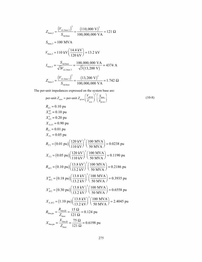
275
( ) ( )
2 2
,base 2
base,2
3 ,base
110,000 V121
100,000,000 VA
LLVZ
S φ
= = = Ω
base,3 100 MVAS =
base,3
14.4 kV110 kV 13.2 kV
120 kVV = =
( )
3 ,base
base,3
,base 3
100,000,000 VA4374 A
3 3 13,200 VLL
SI
Vφ= = =
( ) ( )
2 2
,base 3
base,3
3 ,base
13,200 V1.742
100,000,000 VA
LLVZ
S φ
= = = Ω
The per-unit impedances expressed on the system base are:
2
given newnew given
new given
per-unit per-unit V SZ ZV S
= (10-8)
1 0.10 puGR = 1 0.10 puGX =′′ 1 0.20 puGX =′ , 1 0.90 puS GX = 1 0.01 puTR = 1 0.05 puTX =
( )2
2
120 kV 100 MVA0.01 pu 0.0238 pu
110 kV 50 MVATR = =
( )2
2
120 kV 100 MVA0.05 pu 0.1190 pu
110 kV 50 MVATX = =
( )2
2
13.8 kV 100 MVA0.10 pu 0.2186 pu
13.2 kV 50 MVAMR = =
( )2
2
13.8 kV 100 MVA0.18 pu 0.3935 pu
13.2 kV 50 MVAMX = =′′
( )2
2
13.8 kV 100 MVA0.30 pu 0.6558 pu
13.2 kV 50 MVAMX = =′
( )2
, 2
13.8 kV 100 MVA1.10 pu 2.4045 pu
13.2 kV 50 MVAS MX = =
line,
line,pu
base
150.124 pu
121
RR
ZΩ Ω= = =
Ω
line,
line,pu
base
750.6198 pu
121
XX
ZΩ Ω= = =
Ω

276
The assumption that the system is initially unloaded means that the internal generated voltages of the
generator and motor are = 1.00∠0° before the fault. The resulting per-unit equivalent circuit of the power
system is shown below. Note that all three synchronous machine reactances are shown for each
synchronous machine.
+
-
G1
0.10
j0.10
j0.20
j0.90
L1
T1
j0.1190
+
-
M2
0.2186
j0.3935
j0.6558
j2.4045
T2
j0.6198 0.02380.1240.01j0.05
1.00∠0° 1.00∠0°
1 32 4
(a) Note that the fault occurs at “Bus 3”, which is the high-voltage side of transformer 2T . The input file
for this power system ignoring resistances is shown below.
% File describing the power system of Problem 12-7, ignoring% resistances.%% System data has the form:%SYSTEM name baseMVASYSTEM Prob12_7a 100%% Bus data has the form:%BUS name voltsBUS One 1.00BUS Two 1.00BUS Three 1.00BUS Four 1.00%% Note that transformers T1 and T2 are treated as "transmission lines"% here. Transmission line data has the form:%LINE from to Rse Xse Gsh Bsh X0 VisLINE One Two 0.0000 0.0500 0.000 0.000 0.000 0LINE Two Three 0.0000 0.6198 0.000 0.000 0.000 0LINE Three Four 0.0000 0.1190 0.000 0.000 0.000 0%% Generator data has the form:%GENERATOR bus R Xs Xp Xpp X2 X0GENERATOR One 0.00 0.90 0.20 0.10 0.00 0.00%% Motor data has the form:%MOTOR bus R Xs Xp Xpp X2 X0MOTOR Four 0.0000 2.4045 0.6558 0.3935 0.00 0.00%% type data has the form:
277
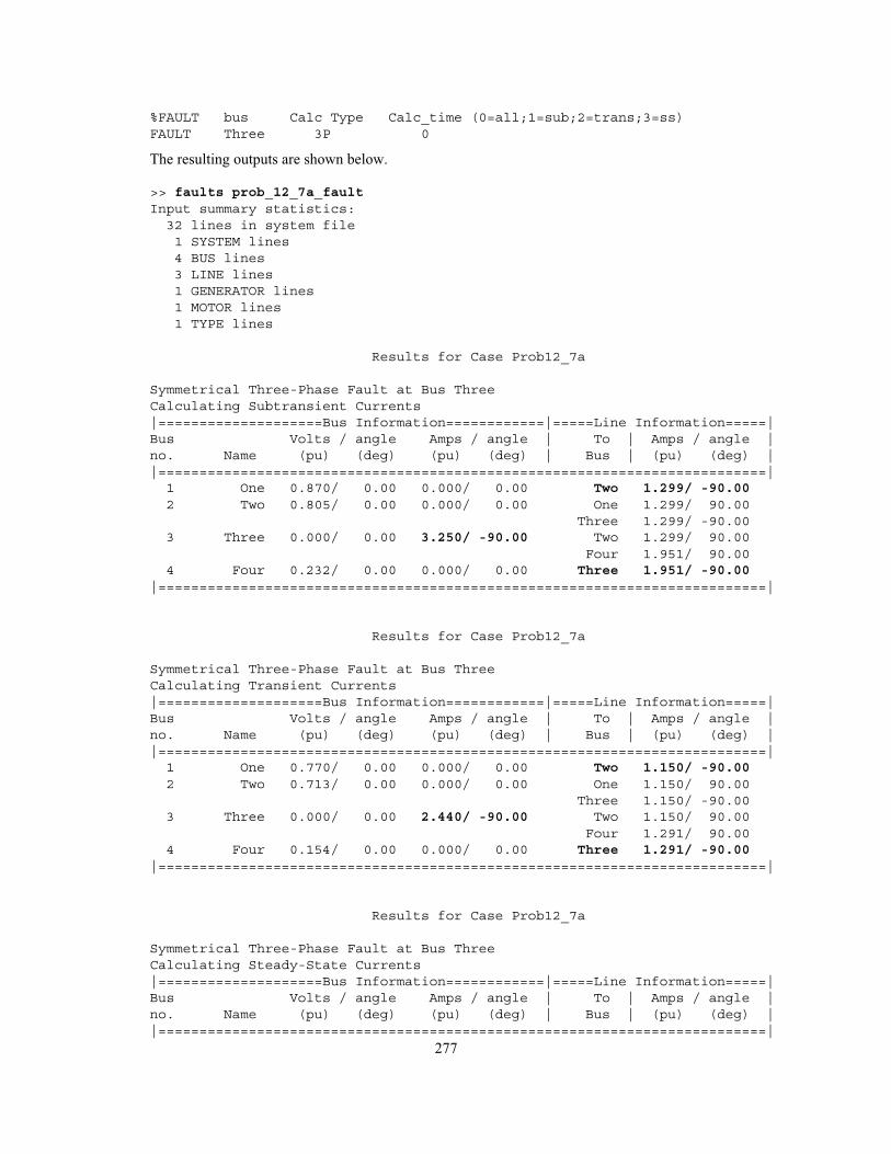
%FAULT bus Calc Type Calc_time (0=all;1=sub;2=trans;3=ss)FAULT Three 3P 0
The resulting outputs are shown below.
>> faults prob_12_7a_faultInput summary statistics:32 lines in system file1 SYSTEM lines4 BUS lines3 LINE lines1 GENERATOR lines1 MOTOR lines1 TYPE lines
Results for Case Prob12_7a
Symmetrical Three-Phase Fault at Bus ThreeCalculating Subtransient Currents|====================Bus Information============|=====Line Information=====|Bus Volts / angle Amps / angle | To | Amps / angle |no. Name (pu) (deg) (pu) (deg) | Bus | (pu) (deg) ||==========================================================================|1 One 0.870/ 0.00 0.000/ 0.00 Two 1.299/ -90.002 Two 0.805/ 0.00 0.000/ 0.00 One 1.299/ 90.00
Three 1.299/ -90.003 Three 0.000/ 0.00 3.250/ -90.00 Two 1.299/ 90.00
Four 1.951/ 90.004 Four 0.232/ 0.00 0.000/ 0.00 Three 1.951/ -90.00
|==========================================================================|
Results for Case Prob12_7a
Symmetrical Three-Phase Fault at Bus ThreeCalculating Transient Currents|====================Bus Information============|=====Line Information=====|Bus Volts / angle Amps / angle | To | Amps / angle |no. Name (pu) (deg) (pu) (deg) | Bus | (pu) (deg) ||==========================================================================|1 One 0.770/ 0.00 0.000/ 0.00 Two 1.150/ -90.002 Two 0.713/ 0.00 0.000/ 0.00 One 1.150/ 90.00
Three 1.150/ -90.003 Three 0.000/ 0.00 2.440/ -90.00 Two 1.150/ 90.00
Four 1.291/ 90.004 Four 0.154/ 0.00 0.000/ 0.00 Three 1.291/ -90.00
|==========================================================================|
Results for Case Prob12_7a
Symmetrical Three-Phase Fault at Bus ThreeCalculating Steady-State Currents|====================Bus Information============|=====Line Information=====|Bus Volts / angle Amps / angle | To | Amps / angle |no. Name (pu) (deg) (pu) (deg) | Bus | (pu) (deg) ||==========================================================================|
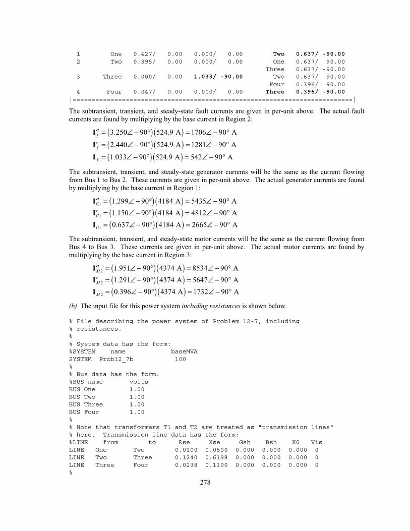
278
1 One 0.427/ 0.00 0.000/ 0.00 Two 0.637/ -90.002 Two 0.395/ 0.00 0.000/ 0.00 One 0.637/ 90.00
Three 0.637/ -90.003 Three 0.000/ 0.00 1.033/ -90.00 Two 0.637/ 90.00
Four 0.396/ 90.004 Four 0.047/ 0.00 0.000/ 0.00 Three 0.396/ -90.00
|==========================================================================|
The subtransient, transient, and steady-state fault currents are given in per-unit above. The actual fault
currents are found by multiplying by the base current in Region 2:
( ) ( )3.250 90 524.9 A 1706 90 Af = ∠ − ° = ∠ − °′′I
( ) ( )2.440 90 524.9 A 1281 90 Af = ∠ − ° = ∠ − °′I
( ) ( )1.033 90 524.9 A 542 90 Af = ∠ − ° = ∠ − °I
The subtransient, transient, and steady-state generator currents will be the same as the current flowing
from Bus 1 to Bus 2. These currents are given in per-unit above. The actual generator currents are found
by multiplying by the base current in Region 1:
( ) ( )1 1.299 90 4184 A 5435 90 AG = ∠ − ° = ∠ − °′′I
( ) ( )1 1.150 90 4184 A 4812 90 AG = ∠ − ° = ∠ − °′I
( ) ( )1 0.637 90 4184 A 2665 90 AG = ∠ − ° = ∠ − °I
The subtransient, transient, and steady-state motor currents will be the same as the current flowing from
Bus 4 to Bus 3. These currents are given in per-unit above. The actual motor currents are found by
multiplying by the base current in Region 3:
( ) ( )2 1.951 90 4374 A 8534 90 AM = ∠ − ° = ∠ − °′′I
( ) ( )2 1.291 90 4374 A 5647 90 AM = ∠ − ° = ∠ − °′I
( ) ( )2 0.396 90 4374 A 1732 90 AM = ∠ − ° = ∠ − °I
(b) The input file for this power system including resistances is shown below.
% File describing the power system of Problem 12-7, including% resistances.%% System data has the form:%SYSTEM name baseMVASYSTEM Prob12_7b 100%% Bus data has the form:%BUS name voltsBUS One 1.00BUS Two 1.00BUS Three 1.00BUS Four 1.00%% Note that transformers T1 and T2 are treated as "transmission lines"% here. Transmission line data has the form:%LINE from to Rse Xse Gsh Bsh X0 VisLINE One Two 0.0100 0.0500 0.000 0.000 0.000 0LINE Two Three 0.1240 0.6198 0.000 0.000 0.000 0LINE Three Four 0.0238 0.1190 0.000 0.000 0.000 0%
279
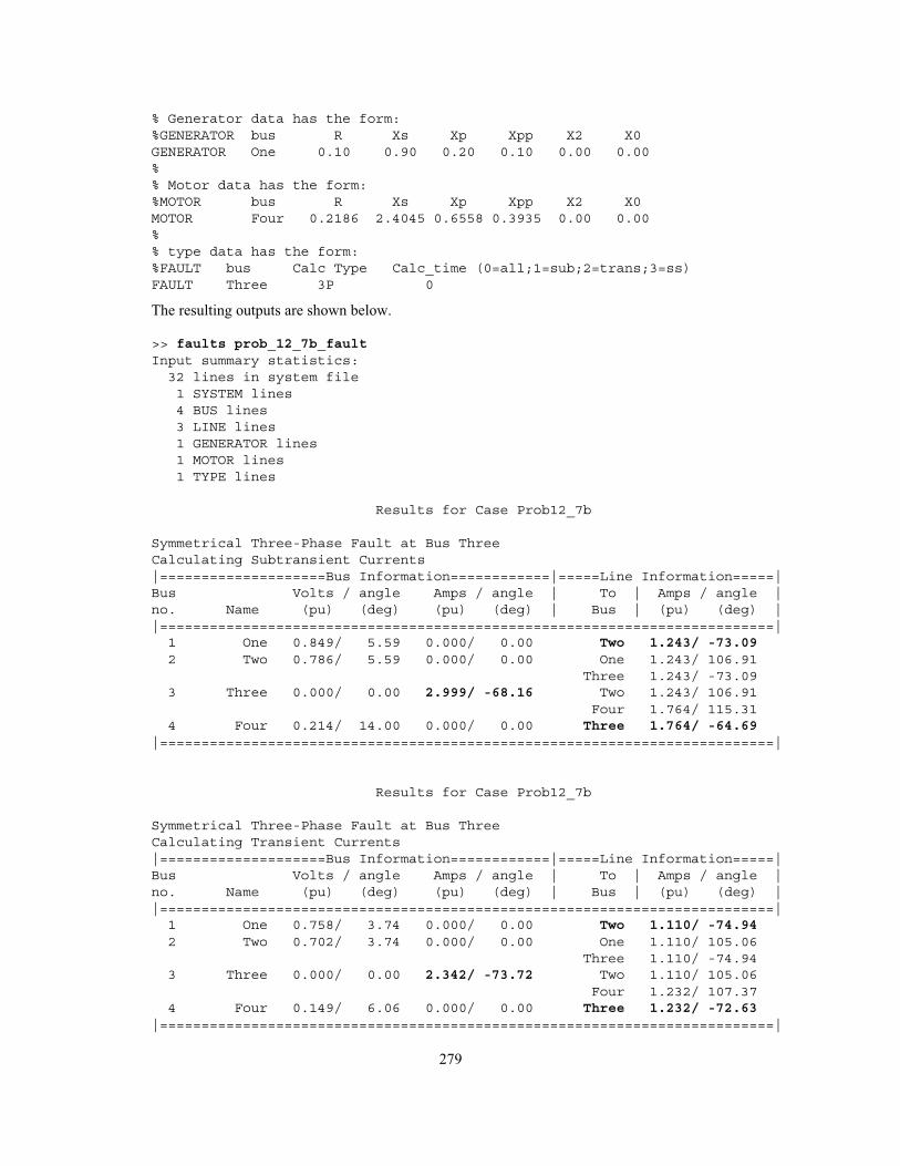
% Generator data has the form:%GENERATOR bus R Xs Xp Xpp X2 X0GENERATOR One 0.10 0.90 0.20 0.10 0.00 0.00%% Motor data has the form:%MOTOR bus R Xs Xp Xpp X2 X0MOTOR Four 0.2186 2.4045 0.6558 0.3935 0.00 0.00%% type data has the form:%FAULT bus Calc Type Calc_time (0=all;1=sub;2=trans;3=ss)FAULT Three 3P 0
The resulting outputs are shown below.
>> faults prob_12_7b_faultInput summary statistics:32 lines in system file1 SYSTEM lines4 BUS lines3 LINE lines1 GENERATOR lines1 MOTOR lines1 TYPE lines
Results for Case Prob12_7b
Symmetrical Three-Phase Fault at Bus ThreeCalculating Subtransient Currents|====================Bus Information============|=====Line Information=====|Bus Volts / angle Amps / angle | To | Amps / angle |no. Name (pu) (deg) (pu) (deg) | Bus | (pu) (deg) ||==========================================================================|1 One 0.849/ 5.59 0.000/ 0.00 Two 1.243/ -73.092 Two 0.786/ 5.59 0.000/ 0.00 One 1.243/ 106.91
Three 1.243/ -73.093 Three 0.000/ 0.00 2.999/ -68.16 Two 1.243/ 106.91
Four 1.764/ 115.314 Four 0.214/ 14.00 0.000/ 0.00 Three 1.764/ -64.69
|==========================================================================|
Results for Case Prob12_7b
Symmetrical Three-Phase Fault at Bus ThreeCalculating Transient Currents|====================Bus Information============|=====Line Information=====|Bus Volts / angle Amps / angle | To | Amps / angle |no. Name (pu) (deg) (pu) (deg) | Bus | (pu) (deg) ||==========================================================================|1 One 0.758/ 3.74 0.000/ 0.00 Two 1.110/ -74.942 Two 0.702/ 3.74 0.000/ 0.00 One 1.110/ 105.06
Three 1.110/ -74.943 Three 0.000/ 0.00 2.342/ -73.72 Two 1.110/ 105.06
Four 1.232/ 107.374 Four 0.149/ 6.06 0.000/ 0.00 Three 1.232/ -72.63
|==========================================================================|
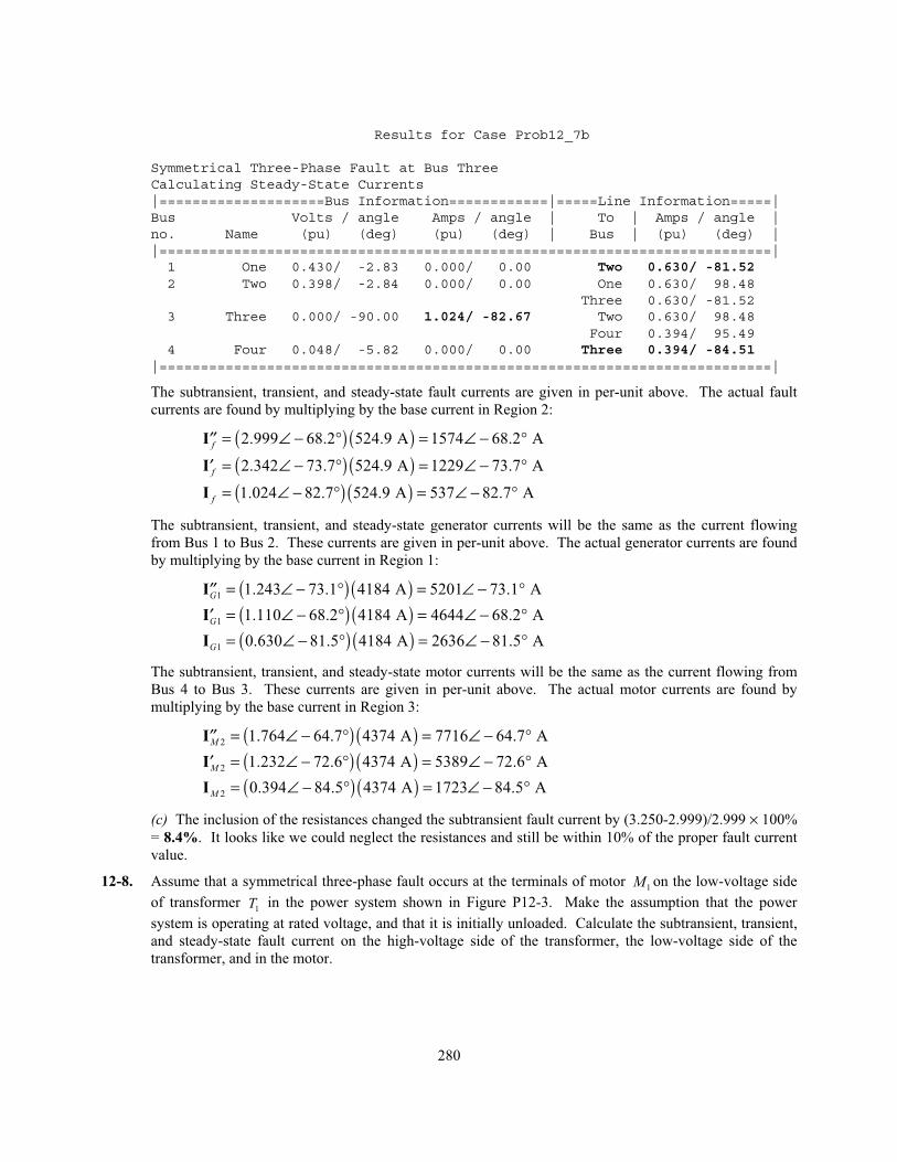
280
Results for Case Prob12_7b
Symmetrical Three-Phase Fault at Bus ThreeCalculating Steady-State Currents|====================Bus Information============|=====Line Information=====|Bus Volts / angle Amps / angle | To | Amps / angle |no. Name (pu) (deg) (pu) (deg) | Bus | (pu) (deg) ||==========================================================================|1 One 0.430/ -2.83 0.000/ 0.00 Two 0.630/ -81.522 Two 0.398/ -2.84 0.000/ 0.00 One 0.630/ 98.48
Three 0.630/ -81.523 Three 0.000/ -90.00 1.024/ -82.67 Two 0.630/ 98.48
Four 0.394/ 95.494 Four 0.048/ -5.82 0.000/ 0.00 Three 0.394/ -84.51
|==========================================================================|
The subtransient, transient, and steady-state fault currents are given in per-unit above. The actual fault
currents are found by multiplying by the base current in Region 2:
( ) ( )2.999 68.2 524.9 A 1574 68.2 Af = ∠ − ° = ∠ − °′′I
( ) ( )2.342 73.7 524.9 A 1229 73.7 Af = ∠ − ° = ∠ − °′I
( ) ( )1.024 82.7 524.9 A 537 82.7 Af = ∠ − ° = ∠ − °I
The subtransient, transient, and steady-state generator currents will be the same as the current flowing
from Bus 1 to Bus 2. These currents are given in per-unit above. The actual generator currents are found
by multiplying by the base current in Region 1:
( ) ( )1 1.243 73.1 4184 A 5201 73.1 AG = ∠ − ° = ∠ − °′′I
( ) ( )1 1.110 68.2 4184 A 4644 68.2 AG = ∠ − ° = ∠ − °′I
( ) ( )1 0.630 81.5 4184 A 2636 81.5 AG = ∠ − ° = ∠ − °I
The subtransient, transient, and steady-state motor currents will be the same as the current flowing from
Bus 4 to Bus 3. These currents are given in per-unit above. The actual motor currents are found by
multiplying by the base current in Region 3:
( ) ( )2 1.764 64.7 4374 A 7716 64.7 AM = ∠ − ° = ∠ − °′′I
( ) ( )2 1.232 72.6 4374 A 5389 72.6 AM = ∠ − ° = ∠ − °′I
( ) ( )2 0.394 84.5 4374 A 1723 84.5 AM = ∠ − ° = ∠ − °I
(c) The inclusion of the resistances changed the subtransient fault current by (3.250-2.999)/2.999 × 100%
= 8.4%. It looks like we could neglect the resistances and still be within 10% of the proper fault current
value.
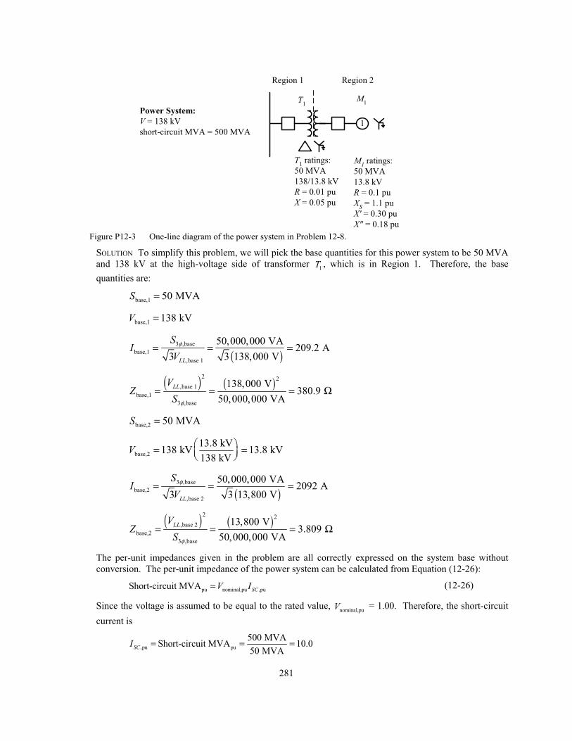
12-8. Assume that a symmetrical three-phase fault occurs at the terminals of motor 1M on the low-voltage side
of transformer 1T in the power system shown in Figure P12-3. Make the assumption that the power
system is operating at rated voltage, and that it is initially unloaded. Calculate the subtransient, transient,
and steady-state fault current on the high-voltage side of the transformer, the low-voltage side of the
transformer, and in the motor.
281
1
Power System:
V = 138 kV
short-circuit MVA = 500 MVA
T1
M1
T1 ratings:
50 MVA
138/13.8 kV
R = 0.01 pu
X = 0.05 pu
M1 ratings:
50 MVA
13.8 kV
R = 0.1 pu
XS = 1.1 pu
X' = 0.30 pu
X" = 0.18 pu
Region 1 Region 2
Figure P12-3 One-line diagram of the power system in Problem 12-8.
SOLUTION To simplify this problem, we will pick the base quantities for this power system to be 50 MVA
and 138 kV at the high-voltage side of transformer 1T , which is in Region 1. Therefore, the base
quantities are:
base,1 50 MVAS =
base,1 138 kVV =
( )
3 ,base
base,1
,base 1
50,000,000 VA209.2 A
3 3 138,000 VLL
SI
Vφ= = =
( ) ( )
2 2
,base 1
base,1
3 ,base
138,000 V380.9
50,000,000 VA
LLVZ
S φ
= = = Ω
base,2 50 MVAS =
base,2
13.8 kV138 kV 13.8 kV
138 kVV = =
( )
3 ,base
base,2
,base 2
50,000,000 VA2092 A
3 3 13,800 VLL
SI
Vφ= = =
( ) ( )
2 2
,base 2
base,2
3 ,base
13,800 V3.809
50,000,000 VA
LLVZ
S φ
= = = Ω
The per-unit impedances given in the problem are all correctly expressed on the system base without
conversion. The per-unit impedance of the power system can be calculated from Equation (12-26):
pu nominal,pu ,puShort-circuit MVA SCV I= (12-26)
Since the voltage is assumed to be equal to the rated value, nominal,puV = 1.00. Therefore, the short-circuit
current is
,pu pu
500 MVAShort-circuit MVA 10.0
50 MVASCI = = =
282
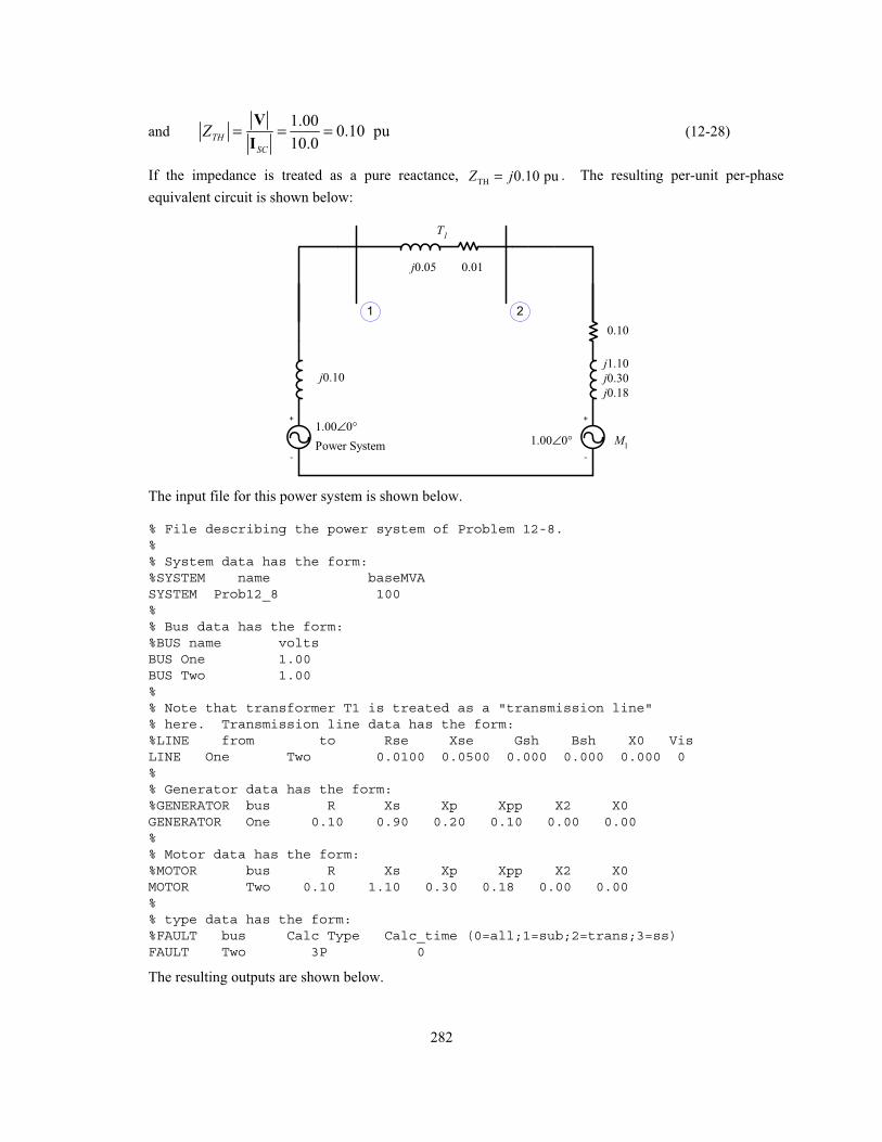
and 1.00
0.10 pu10.0
THSC
Z = = =V
I (12-28)
If the impedance is treated as a pure reactance, TH 0.10 puZ j= . The resulting per-unit per-phase
equivalent circuit is shown below:
Power System
j0.10
j0.05
+
-
M1
0.10
j1.10
j0.30
j0.18
T1
0.01
1.00∠0°1.00∠0°
2
+
-
1
The input file for this power system is shown below.
% File describing the power system of Problem 12-8.%% System data has the form:%SYSTEM name baseMVASYSTEM Prob12_8 100%% Bus data has the form:%BUS name voltsBUS One 1.00BUS Two 1.00%% Note that transformer T1 is treated as a "transmission line"% here. Transmission line data has the form:%LINE from to Rse Xse Gsh Bsh X0 VisLINE One Two 0.0100 0.0500 0.000 0.000 0.000 0%% Generator data has the form:%GENERATOR bus R Xs Xp Xpp X2 X0GENERATOR One 0.10 0.90 0.20 0.10 0.00 0.00%% Motor data has the form:%MOTOR bus R Xs Xp Xpp X2 X0MOTOR Two 0.10 1.10 0.30 0.18 0.00 0.00%% type data has the form:%FAULT bus Calc Type Calc_time (0=all;1=sub;2=trans;3=ss)FAULT Two 3P 0
The resulting outputs are shown below.
283
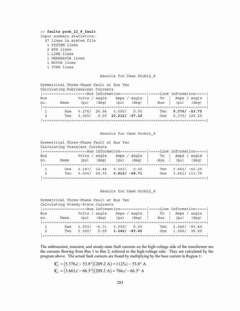
>> faults prob_12_8_faultInput summary statistics:27 lines in system file1 SYSTEM lines2 BUS lines1 LINE lines1 GENERATOR lines1 MOTOR lines1 TYPE lines
Results for Case Prob12_8
Symmetrical Three-Phase Fault at Bus TwoCalculating Subtransient Currents|====================Bus Information============|=====Line Information=====|Bus Volts / angle Amps / angle | To | Amps / angle |no. Name (pu) (deg) (pu) (deg) | Bus | (pu) (deg) ||==========================================================================|1 One 0.274/ 24.94 0.000/ 0.00 Two 5.376/ -53.752 Two 0.000/ 0.00 10.212/ -57.16 One 5.376/ 126.25
|==========================================================================|
Results for Case Prob12_8
Symmetrical Three-Phase Fault at Bus TwoCalculating Transient Currents|====================Bus Information============|=====Line Information=====|Bus Volts / angle Amps / angle | To | Amps / angle |no. Name (pu) (deg) (pu) (deg) | Bus | (pu) (deg) ||==========================================================================|1 One 0.187/ 12.44 0.000/ 0.00 Two 3.661/ -66.252 Two 0.000/ 90.00 6.816/ -68.71 One 3.661/ 113.75
|==========================================================================|
Results for Case Prob12_8
Symmetrical Three-Phase Fault at Bus TwoCalculating Steady-State Currents|====================Bus Information============|=====Line Information=====|Bus Volts / angle Amps / angle | To | Amps / angle |no. Name (pu) (deg) (pu) (deg) | Bus | (pu) (deg) ||==========================================================================|1 One 0.053/ -4.71 0.000/ 0.00 Two 1.046/ -83.402 Two 0.000/ 0.00 1.046/ -83.40 One 1.046/ 96.60
|==========================================================================|
The subtransient, transient, and steady-state fault currents on the high-voltage side of the transformer are
the currents flowing from Bus 1 to Bus 2, referred to the high-voltage side. They are calculated by the
program above. The actual fault currents are found by multiplying by the base current in Region 1:
( ) ( )1 5.376 53.8 209.2 A 1125 53.8 AT = ∠ − ° = ∠ − °′′I
( ) ( )1 3.661 66.3 209.2 A 766 66.3 AT = ∠ − ° = ∠ − °′I
284
( ) ( )1 1.046 83.4 209.2 A 219 83.4 AT = ∠ − ° = ∠ − °I
The subtransient, transient, and steady-state fault currents on the low-voltage side of the transformer are
the fault currents flowing at Bus 2. They are calculated by the program above. The actual fault currents
are found by multiplying by the base current in Region 2:
( ) ( )10.212 57.2 2092 A 21,360 57.2 Af = ∠ − ° = ∠ − °′′I
( ) ( )6.816 68.7 2092 A 14,260 68.7 Af = ∠ − ° = ∠ − °′I
( ) ( )1.046 83.4 2092 A 2188 83.4 Af = ∠ − ° = ∠ − °I
The subtransient, transient, and steady-state motor currents will be the currents that would flow in the
motor if its terminals were short circuited. These per-unit currents will be 1.00/Z for the subtransient and
transient cases, and zero for the steady-state case. (The current from the motor is 0 at steady state because
there is nothing to keep the motor turning of the electrical input to the motor is shorted out.)
2
1.00 04.856 60.9 A
0.10 0.18M j
∠ °= = ∠ − °′′+
I
2
1.00 03.162 71.6 A
0.10 0.30M j
∠ °= = ∠ − °′′+
I
2 0 AM =I
The actual motor currents are found by multiplying by the base current in Region 2:
( ) ( )2 4.856 60.9 2092 A 10,160 60.9 AM = ∠ − ° = ∠ − °′′I
( ) ( )2 3.162 71.6 2092 A 6615 71.6 AM = ∠ − ° = ∠ − °′I
2 0 AM =I
Chapter 13: Unsymmetrical Faults
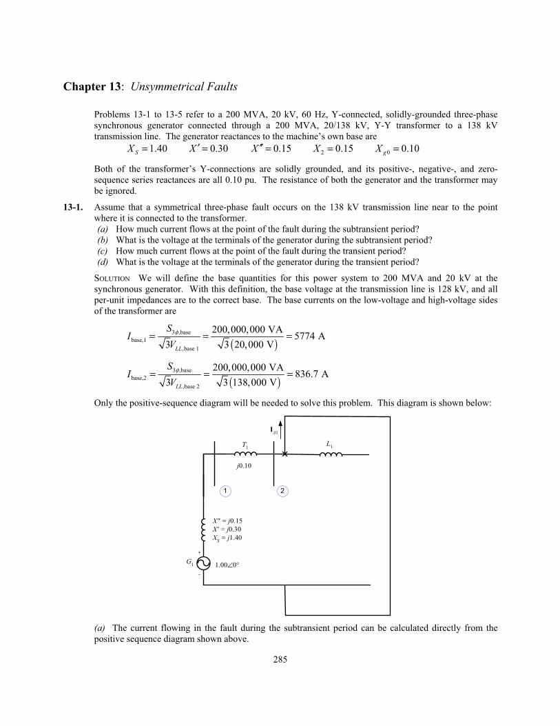
Problems 13-1 to 13-5 refer to a 200 MVA, 20 kV, 60 Hz, Y-connected, solidly-grounded three-phase
synchronous generator connected through a 200 MVA, 20/138 kV, Y-Y transformer to a 138 kV
transmission line. The generator reactances to the machine’s own base are
1.40SX = 0.30X ′ = 0.15X ′′ = 2 0.15X = 0 0.10gX =
Both of the transformer’s Y-connections are solidly grounded, and its positive-, negative-, and zero-
sequence series reactances are all 0.10 pu. The resistance of both the generator and the transformer may
be ignored.
13-1. Assume that a symmetrical three-phase fault occurs on the 138 kV transmission line near to the point
where it is connected to the transformer.
(a) How much current flows at the point of the fault during the subtransient period?
(b) What is the voltage at the terminals of the generator during the subtransient period?
(c) How much current flows at the point of the fault during the transient period?
(d) What is the voltage at the terminals of the generator during the transient period?
SOLUTION We will define the base quantities for this power system to 200 MVA and 20 kV at the
synchronous generator. With this definition, the base voltage at the transmission line is 128 kV, and all
per-unit impedances are to the correct base. The base currents on the low-voltage and high-voltage sides
of the transformer are
( )3 ,base
base,1
,base 1
200,000,000 VA5774 A
3 3 20,000 VLL
SV
φ= = =I
( )3 ,base
base,2
,base 2
200,000,000 VA836.7 A
3 3 138,000 VLL
SV
φ= = =I
Only the positive-sequence diagram will be needed to solve this problem. This diagram is shown below:
G1
X" = j0.15
X' = j0.30
XS = j1.40
L1T
1
j0.10
1.00∠0°
1 2
+
-
IA1
(a) The current flowing in the fault during the subtransient period can be calculated directly from the
positive sequence diagram shown above.
285
1
1.00 04.000 90
0.15 0.10A A j j
∠ °= = = ∠ −+
°
°
I I
The resulting subtransient fault current in amps is
fI = =′′ ( ) ( )4.000 836.7 A 3347 A
(b) The per-unit voltage at the terminals of the generator during the subtransient period is
V V ( ) ( ) ( )1 1 4.000 90 0.10 0.400 0A TjX jφ = = = ∠ − ° = ∠I
The resulting subtransient voltage at the terminals is
V = =( ) ( )0.400 20 kV 8 kVT′′
(c) The current flowing in the fault during the transient period can be calculated directly from the positive
sequence diagram shown above.
1
1.00 02.500 90
0.30 0.10A A j j
∠ °= = = ∠ −+
°
°
I I
The resulting transient fault current in amps is
fI = =′ ( ) ( )2.500 836.7 A 2092 A
(d) The per-unit voltage at the terminals of the generator during the transient period is
V V ( ) ( ) ( )1 1 2.500 90 0.10 0.250 0A TjX jφ = = = ∠ − ° = ∠I
The resulting subtransient voltage at the terminals is
V = =′ ( ) ( )0.250 20 kV 5 kVT
13-2. Assume that a single-line-to-ground fault occurs on the 138 kV transmission line near to the point where
it is connected to the transformer.
(a) How much current flows at the point of the fault during the subtransient period?
(b) What is the voltage at the terminals of the generator during the subtransient period?
(c) How much current flows at the point of the fault during the transient period?
(d) What is the voltage at the terminals of the generator during the transient period?
SOLUTION All three sequence diagrams will be needed to solve this problem. These diagrams must be
connected in series, as shown below:
286