
Instruction Manual - Πολυτεχνική Σχολή 162/HM16229E.pdf · After assembly or...
12
G.U.N.T. Gerätebau GmbH Fahrenberg 14 D-22885 Barsbüttel Germany Phone: ++49 (40) 670854.0 Fax: ++49 (40) 670854.42 E-mail: [email protected] Web: http://www.gunt.de Equipment for Engineering Education Instruction Manual HM 162.29 Sluice Gate
Transcript of Instruction Manual - Πολυτεχνική Σχολή 162/HM16229E.pdf · After assembly or...
G.U.N.T. Gerätebau GmbHFahrenberg 14
D-22885 Barsbüttel
Germany
Phone: ++49 (40) 670854.0
Fax: ++49 (40) 670854.42
E-mail: [email protected]
Web: http://www.gunt.de
Equipment for Engineering Education
Instruction Manual
HM 162.29 Sluice Gate
12/2003
All
Rig
hts
Res
erve
dG
.U.N
.T.G
erät
ebau
Gm
bH,B
arsb
ütte
l,G
erm
any
12/2
003
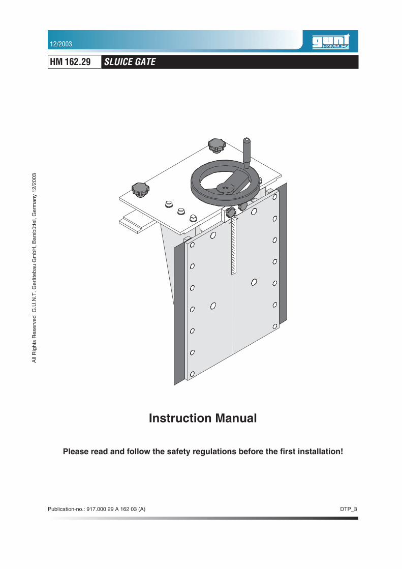
Instruction Manual
Please read and follow the safety regulations before the first installation!
Publication-no.: 917.000 29 A 162 03 (A) DTP_3
HM 162.29 SLUICE GATE
Table of Contents
1 Introduction . . . . . . . . . . . . . . . . . . . . . . . . . . . . . . . . . . . . . . . . 1
2 Unit description . . . . . . . . . . . . . . . . . . . . . . . . . . . . . . . . . . . . . 2
2.1 Components. . . . . . . . . . . . . . . . . . . . . . . . . . . . . . . . . . . . . . . . . . . . 2
2.2 Assembly . . . . . . . . . . . . . . . . . . . . . . . . . . . . . . . . . . . . . . . . . . . . . . 2
2.3 Function . . . . . . . . . . . . . . . . . . . . . . . . . . . . . . . . . . . . . . . . . . . . . . . 3
3 Safety . . . . . . . . . . . . . . . . . . . . . . . . . . . . . . . . . . . . . . . . . . . . 4
3.1 Protection of the unit . . . . . . . . . . . . . . . . . . . . . . . . . . . . . . . . . . . . . 4
4 Theory and experiments . . . . . . . . . . . . . . . . . . . . . . . . . . . . . . 5
4.1 Categorisation of weirs . . . . . . . . . . . . . . . . . . . . . . . . . . . . . . . . . . . 5
4.2 Features of a sluice weir . . . . . . . . . . . . . . . . . . . . . . . . . . . . . . . . . . 5
4.3 Outflow under a sluice weir . . . . . . . . . . . . . . . . . . . . . . . . . . . . . . . . 6
4.4 Water pressure calculation . . . . . . . . . . . . . . . . . . . . . . . . . . . . . . . . 7
4.4.1 Amount of counterforce. . . . . . . . . . . . . . . . . . . . . . . . . . . . . 7
4.4.2 Position of counterforce . . . . . . . . . . . . . . . . . . . . . . . . . . . . 8
4.5 Indications of additional experiments. . . . . . . . . . . . . . . . . . . . . . . . . 8
5 Appendix . . . . . . . . . . . . . . . . . . . . . . . . . . . . . . . . . . . . . . . . . . 9
5.1 Technical data . . . . . . . . . . . . . . . . . . . . . . . . . . . . . . . . . . . . . . . . . . 9
HM 162.29 SLUICE GATE
DTP_312/2003
All
Rig
hts
Res
erve
dG
.U.N
.T.G
erät
ebau
Gm
bH,B
arsb
ütte
l,G
erm
any
12/2
003
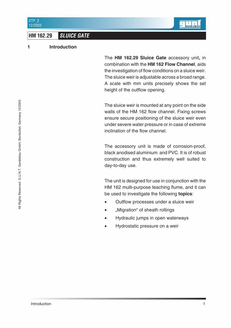
1 Introduction
The HM 162.29 Sluice Gate accessory unit, incombination with the HM 162 Flow Channel, aidsthe investigation of flow conditions on a sluice weir.The sluice weir is adjustable across a broad range.A scale with mm units precisely shows the setheight of the outflow opening.
The sluice weir is mounted at any point on the sidewalls of the HM 162 flow channel. Fixing screwsensure secure positioning of the sluice weir evenunder severe water pressure or in case of extremeinclination of the flow channel.
The accessory unit is made of corrosion-proof,black anodised aluminium and PVC. It is of robustconstruction and thus extremely well suited today-to-day use.
The unit is designed for use in conjunction with theHM 162 multi-purpose teaching flume, and it canbe used to investigate the following topics:
• Outflow processes under a sluice weir
• „Migration“ of sheath rollings
• Hydraulic jumps in open waterways
• Hydrostatic pressure on a weir
Introduction 1
HM 162.29 SLUICE GATE
DTP_312/2003
All
Rig
hts
Res
erve
dG
.U.N
.T.G
erät
ebau
Gm
bH,B
arsb
ütte
l,G
erm
any
12/2
003
2 Unit description
The HM 162.29 adjustable undershot weir ac-cessory unit is designed for installation in the HM162 multi-purpose teaching flume. The height ofthe outflow cross-section is adjustable, and is dis-played on a scale in mm units.
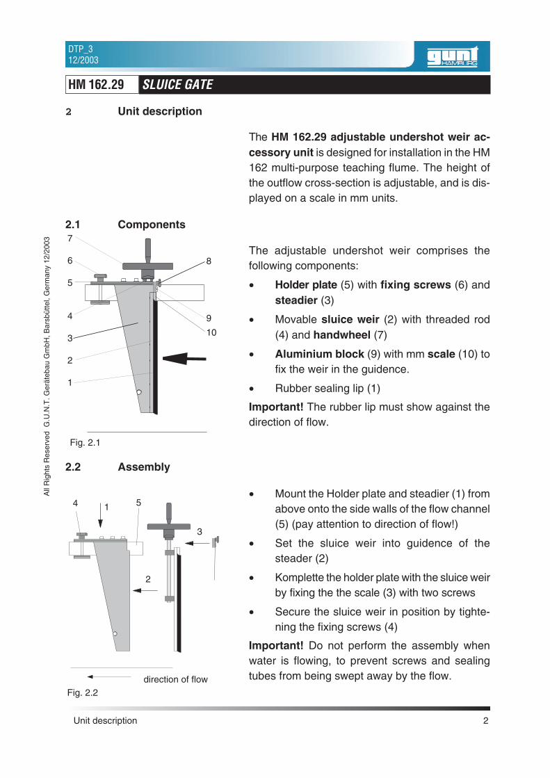
2.1 Components
The adjustable undershot weir comprises thefollowing components:
• Holder plate (5) with fixing screws (6) andsteadier (3)
• Movable sluice weir (2) with threaded rod(4) and handwheel (7)
• Aluminium block (9) with mm scale (10) tofix the weir in the guidence.
• Rubber sealing lip (1)
Important! The rubber lip must show against thedirection of flow.
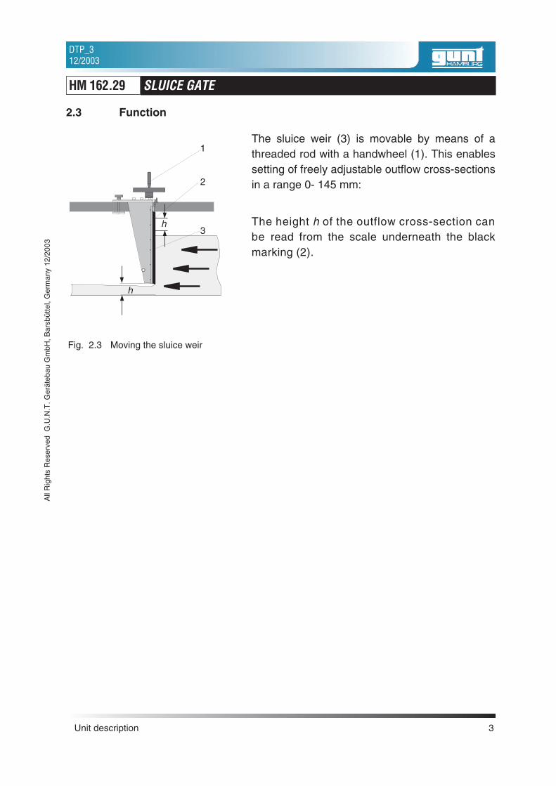
2.2 Assembly
• Mount the Holder plate and steadier (1) fromabove onto the side walls of the flow channel(5) (pay attention to direction of flow!)
• Set the sluice weir into guidence of thesteader (2)
• Komplette the holder plate with the sluice weirby fixing the the scale (3) with two screws
• Secure the sluice weir in position by tighte-ning the fixing screws (4)
Important! Do not perform the assembly whenwater is flowing, to prevent screws and sealingtubes from being swept away by the flow.
Unit description 2
HM 162.29 SLUICE GATE
DTP_312/2003
All
Rig
hts
Res
erve
dG
.U.N
.T.G
erät
ebau
Gm
bH,B
arsb
ütte
l,G
erm
any
12/2
003
Fig. 2.1
7
6
5
4
3
2
1
8
9
10
Fig. 2.2direction of flow
1
2
3
4 5
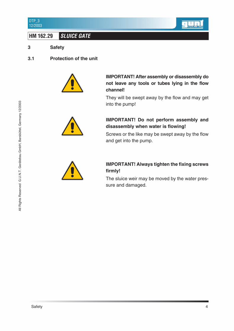
2.3 Function
The sluice weir (3) is movable by means of athreaded rod with a handwheel (1). This enablessetting of freely adjustable outflow cross-sectionsin a range 0- 145 mm:
The height h of the outflow cross-section canbe read from the scale underneath the blackmarking (2).
Unit description 3
HM 162.29 SLUICE GATE
DTP_312/2003
All
Rig
hts
Res
erve
dG
.U.N
.T.G
erät
ebau
Gm
bH,B
arsb
ütte
l,G
erm
any
12/2
003
Fig. 2.3 Moving the sluice weir
1
2
3
h
h
3 Safety
3.1 Protection of the unit
IMPORTANT! After assembly or disassembly donot leave any tools or tubes lying in the flowchannel!
They will be swept away by the flow and may getinto the pump!
IMPORTANT! Do not perform assembly anddisassembly when water is flowing!
Screws or the like may be swept away by the flowand get into the pump.
IMPORTANT! Always tighten the fixing screwsfirmly!
The sluice weir may be moved by the water pres-sure and damaged.
Safety 4
HM 162.29 SLUICE GATE
DTP_312/2003
All
Rig
hts
Res
erve
dG
.U.N
.T.G
erät
ebau
Gm
bH,B
arsb
ütte
l,G
erm
any
12/2
003
4 Theory and experiments
4.1 Categorisation of weirs
Weirs can be categorised as fixed weirs andmovable weirs. Movable weirs are usedwhenever as constant a head water level aspossible is required, and when a certain height ofdamming must not be exceeded with the highest ofhigh waters.
In the case of rivers with heavy bed load, a movableweir may be used in addition to a fixed weir, toprevent bed load colmation upstream of the fixedweir and to be able to conduct the bed load into thedownstream water.
The sluice weir dealt with here is a movable weir. Interms of its function, the weir is a sluice, i.e. thewater does not flow over it, but under it.
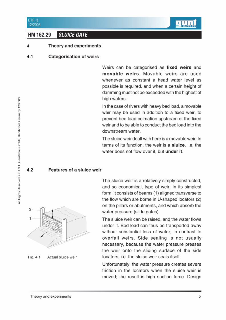
4.2 Features of a sluice weir
The sluice weir is a relatively simply constructed,and so economical, type of weir. In its simplestform, it consists of beams (1) aligned transverse tothe flow which are borne in U-shaped locators (2)on the pillars or abutments, and which absorb thewater pressure (slide gates).
The sluice weir can be raised, and the water flowsunder it. Bed load can thus be transported awaywithout substantial loss of water, in contrast tooverfall weirs. Side sealing is not usuallynecessary, because the water pressure pressesthe weir onto the sliding surface of the sidelocators, i.e. the sluice weir seals itself.
Unfortunately, the water pressure creates severefriction in the locators when the sluice weir ismoved; the result is high suction force. Design
Theory and experiments 5
HM 162.29 SLUICE GATE
DTP_312/2003
All
Rig
hts
Res
erve
dG
.U.N
.T.G
erät
ebau
Gm
bH,B
arsb
ütte
l,G
erm
any
12/2
003
Fig. 4.1 Actual sluice weir
2
1
modifications can be made to reduce the friction,and special forms of sluice weir (Stoney sluice,dual sluice etc.) are created.
If the entire height of the raceway is to be openedup, the sluice weir must be drawn a very long wayup, requiring an extremely high structure.
4.3 Outflow under a sluice weir
Because the sluice weir is of great importance inwater engineering, researchers have investigatedthe hydraulic conditions in great detail.
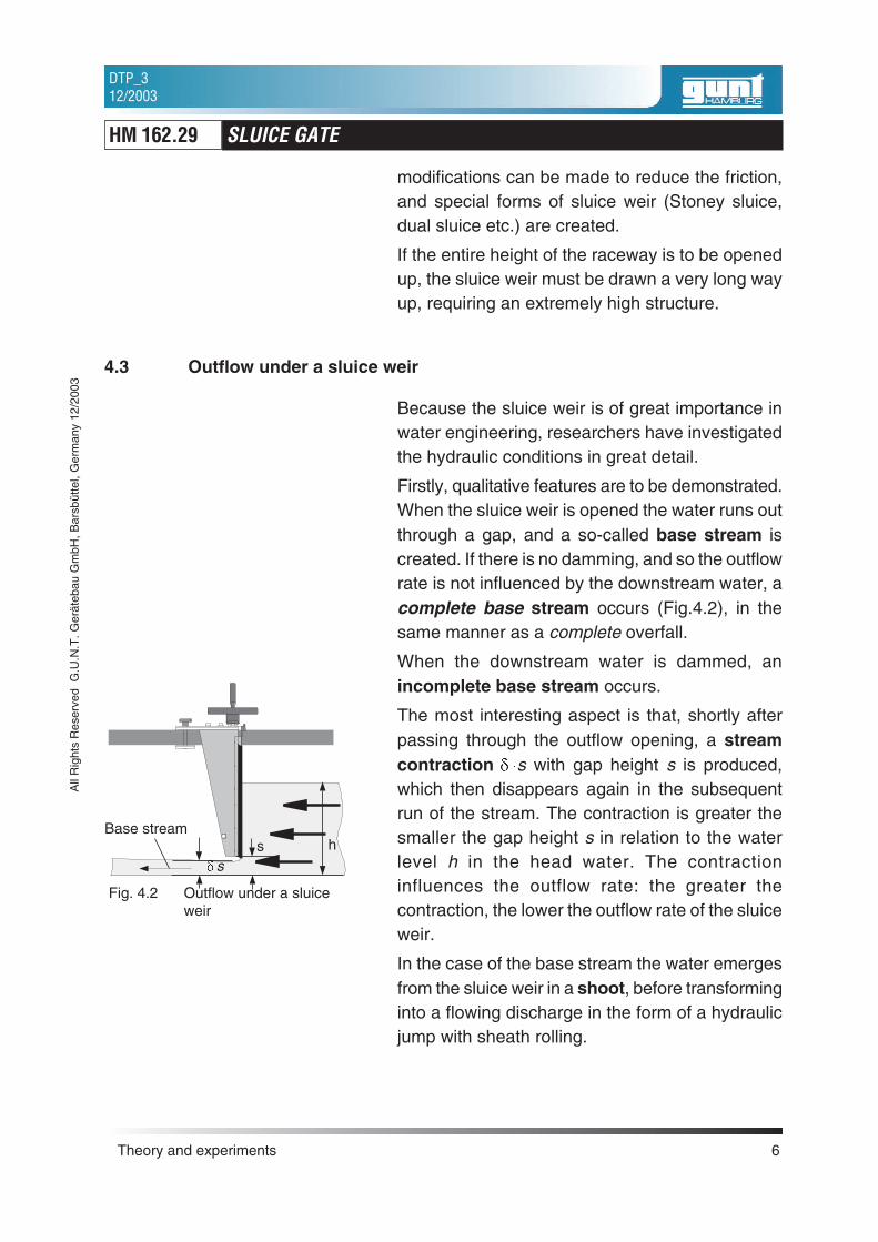
Firstly, qualitative features are to be demonstrated.When the sluice weir is opened the water runs outthrough a gap, and a so-called base stream iscreated. If there is no damming, and so the outflowrate is not influenced by the downstream water, acomplete base stream occurs (Fig.4.2), in thesame manner as a complete overfall.
When the downstream water is dammed, anincomplete base stream occurs.
The most interesting aspect is that, shortly afterpassing through the outflow opening, a streamcontraction � �s with gap height s is produced,which then disappears again in the subsequentrun of the stream. The contraction is greater thesmaller the gap height s in relation to the waterlevel h in the head water. The contractioninfluences the outflow rate: the greater thecontraction, the lower the outflow rate of the sluiceweir.
In the case of the base stream the water emergesfrom the sluice weir in a shoot, before transforminginto a flowing discharge in the form of a hydraulicjump with sheath rolling.
Theory and experiments 6
HM 162.29 SLUICE GATE
DTP_312/2003
All
Rig
hts
Res
erve
dG
.U.N
.T.G
erät
ebau
Gm
bH,B
arsb
ütte
l,G
erm
any
12/2
003
Fig. 4.2 Outflow under a sluiceweir
� s
Base streams h
4.4 Water pressure calculation
The water pressure acting on the sluice weirgenerates a counterforce on it. The size andposition of this counterforce is to be ascertainedfor the complete base stream (without damming).
The flow speed of the water is usually quite low, sothe inherent impetus in the water is ignored.
4.4.1 Amount of counterforce
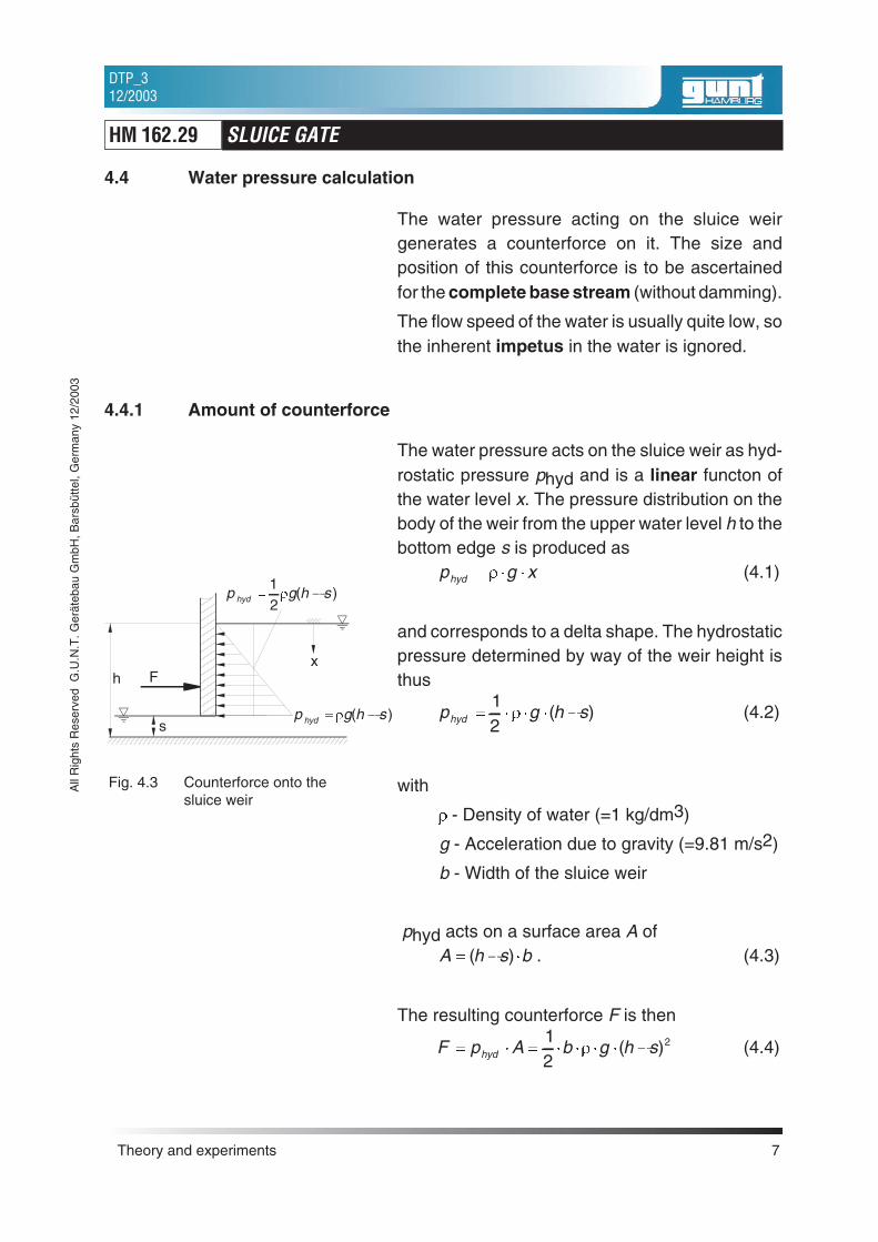
The water pressure acts on the sluice weir as hyd-rostatic pressure phyd and is a linear functon ofthe water level x. The pressure distribution on thebody of the weir from the upper water level h to thebottom edge s is produced as
p g xhyd � � �� (4.1)
and corresponds to a delta shape. The hydrostaticpressure determined by way of the weir height isthus
p g h shyd � � � � �12
� ( ) (4.2)
with
� - Density of water (=1 kg/dm3)
g - Acceleration due to gravity (=9.81 m/s2)
b - Width of the sluice weir
phyd acts on a surface area A ofA h s b� � �( ) . (4.3)
The resulting counterforce F is then
F p A b g h shyd� � � � � � � �12
2� ( ) (4.4)
Theory and experiments 7
HM 162.29 SLUICE GATE
DTP_312/2003
All
Rig
hts
Res
erve
dG
.U.N
.T.G
erät
ebau
Gm
bH,B
arsb
ütte
l,G
erm
any
12/2
003
Fig. 4.3 Counterforce onto thesluice weir
F
s
h
p g h shyd � �12� ( )
p g h shyd � �� ( )
x
Example:
Measured values with Q=5.9 m3/h flow:
h=117.5 mm
s=30 mm
b=590 mm
The counterforce F is calculated as
F = 22 N
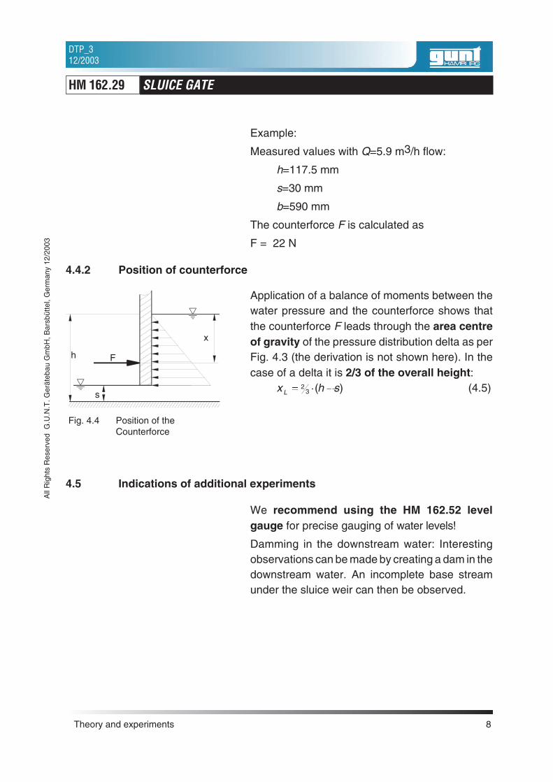
4.4.2 Position of counterforce
Application of a balance of moments between thewater pressure and the counterforce shows thatthe counterforce F leads through the area centreof gravity of the pressure distribution delta as perFig. 4.3 (the derivation is not shown here). In thecase of a delta it is 2/3 of the overall height:
x h sL � � �23 ( ) (4.5)
4.5 Indications of additional experiments
We recommend using the HM 162.52 levelgauge for precise gauging of water levels!
Damming in the downstream water: Interestingobservations can be made by creating a dam in thedownstream water. An incomplete base streamunder the sluice weir can then be observed.
Theory and experiments 8
HM 162.29 SLUICE GATE
DTP_312/2003
All
Rig
hts
Res
erve
dG
.U.N
.T.G
erät
ebau
Gm
bH,B
arsb
ütte
l,G
erm
any
12/2
003
Fig. 4.4 Position of theCounterforce
F
s
h
xL
5 Appendix
5.1 Technical data
Material: PVC and Aluminiumalloy, black anodised
Dimensions:(L x W x H) 370 x 263 x 710 mm
Opening range: 0-145 mm
Scale: 0-150 mmAccuracy: 1 mm
Appendix 9
HM 162.29 SLUICE GATE
DTP_312/2003
All
Rig
hts
Res
erve
dG
.U.N
.T.G
erät
ebau
Gm
bH,B
arsb
ütte
l,G
erm
any
12/2
003