Installation Reference, Volvo Penta IPS Hull Insert and Engine...
2
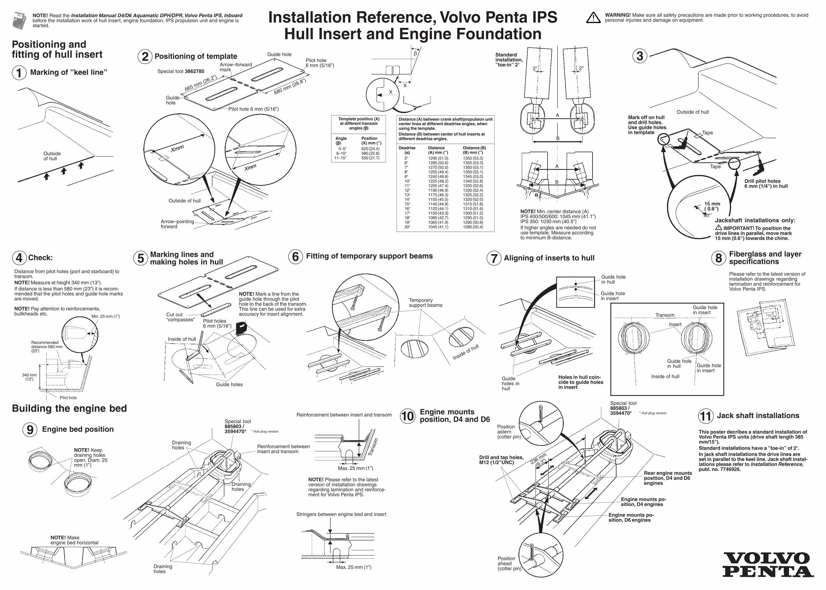
Template position (X) at different transom angles ( β β β) Angle Position ( β β β) (X) mm (’’) 0–5° 620 (24.4) 6–10° 580 (22.8) 11–15° 550 (21.7) Installation Reference, Volvo Penta IPS Hull Insert and Engine Foundation Building the engine bed Engine bed position Positioning and fitting of hull insert 1 Marking of ”keel line” Outside of hull NOTE! Keep draining holes open. Diam. 25 mm (1”) NOTE! Make engine bed horizontal Reinforcement between insert and transom Special tool 885803 / 3594470* Draining holes Draining holes Draining holes Transom Max. 25 mm (1”) Max. 25 mm (1”) 6 Fitting of temporary support beams Temporary support beams Inside of hull Holes in hull coin- cide to guide holes in insert Guide hole in insert Guide hole in hull Aligning of inserts to hull 7 9 Guide holes in hull Engine mounts position, D4 and D6 10 Drill and tap holes, M12 (1/2”UNC) Position ahead (cotter pin) Position astern (cotter pin) Engine mounts po- sition, D4 engines Engine mounts po- sition, D6 engines Rear engine mounts position, D4 and D6 engines 236 mm (9.3”) Mark off on hull and drill holes. Use guide holes in template Drill pilot holes 6 mm (1/4'') in hull Tape Outside of hull 3 Jackshaft installations only: IMPORTANT! To position the drive lines in parallel, move mark 15 mm (0.6'') towards the chine. 15 mm ( 0.6'') Tape 8 Fiberglass and layer specifications Please refer to the latest version of installation drawings regarding lamination and reinforcement for Volvo Penta IPS. Special tool 885803 / 3594470* This poster decribes a standard installation of Volvo Penta IPS units (drive shaft length 385 mm/15"). Standard installations have a ”toe-in” of 2°. In jack shaft installations the drive lines are set in parallel to the keel line. Jack shaft instal- lations please refer to Installation Reference, publ. no. 7746926. NOTE! Please refer to the latest version of installation drawings regarding lamination and reinforce- ment for Volvo Penta IPS. * Hull plug version * Hull plug version Jack shaft installations 11 Arrow–pointing forward Outside of hull 2 Positioning of template Arrow–forward mark Pilot hole 6 mm (5/16”) Guide hole Guide hole Special tool 3862785 Pilot hole 6 mm (5/16”) 680 mm (26.8”) 665 mm (26.2”) Distance (A) between crank shaft/propulsion unit center lines at different deadrise angles, when using the template. Distance (B) between center of hull inserts at different deadrise angles. Deadrise Distance Distance (B) ( α α α) (A) mm (’’) (B) mm (”) 5° 1295 (51.0) 1355 (53.3) 6° 1285 (50.6) 1355 (53.3) 7° 1270 (50.0) 1350 (53.1) 8° 1255 (49.4) 1350 (53.1) 9° 1240 (48.8) 1345 (53.0) 10° 1225 (48.2) 1340 (52.8) 11° 1205 (47.4) 1335 (52.6) 12° 1190 (46.9) 1330 (52.4) 13° 1175 (46.3) 1325 (52.2) 14° 1155 (45.5) 1320 (52.0) 15° 1140 (44.9) 1315 (51.8) 16° 1120 (44.1) 1310 (51.6) 17° 1100 (43.3) 1300 (51.2) 18° 1085 (42.7) 1295 (51.0) 19° 1065 (41.9) 1290 (50.8) 20° 1045 (41.1) 1280 (50.4) A α α α B β X X A B 2° 2° Standard installation, ”toe-in” 2° Stringers between engine bed and insert Reinforcement between insert and transom Transom Guide hole in hull Guide hole in insert Inside of hull Insert Cut out “compasses” Pilot holes 6 mm (5/16”) Inside of hull 5 Marking lines and making holes in hull NOTE! Mark a line from the guide hole through the pilot hole to the back of the transom. This line can be used for extra accuracy for insert alignment. Guide holes 4 Check: Distance from pilot holes (port and starboard) to transom. NOTE! Measure at height 340 mm (13”). If distance is less than 580 mm (23”) it is recom- mended that the pilot holes and guide hole marks are moved. NOTE! Pay attention to reinforcements, bullkheads etc. Recommended distance 580 mm (23”) 340 mm (13”) Pilot hole Min. 25 mm (1”) Guide hole in insert NOTE! Read the Installation Manual D4/D6 Aquamatic DPH/DPR, Volvo Penta IPS, Inboard before the installation work of hull insert, engine foundation, IPS propulsion unit and engine is started. WARNING! Make sure all safety precautions are made prior to working procedures, to avoid personal injuries and damage on equipment. NOTE! Min. center distance (A) IPS 400/500/600: 1045 mm (41.1”) IPS 350: 1030 mm (40.5”) If higher angles are needed do not use template. Measure according to minimum B-distance.
Transcript of Installation Reference, Volvo Penta IPS Hull Insert and Engine...
Template position (X)at different transom
angles (βββββ)
Angle Position (βββββ) (X) mm (’’)
0–5° 620 (24.4)6–10° 580 (22.8)
11–15° 550 (21.7)
Installation Reference, Volvo Penta IPSHull Insert and Engine Foundation
Building the engine bed
Engine bed position
Positioning andfitting of hull insert
1 Marking of ”keel line”
Outsideof hull
NOTE! Keepdraining holesopen. Diam. 25mm (1”)
NOTE! Makeengine bed horizontal
Reinforcement betweeninsert and transom
Special tool885803 /3594470*
Drainingholes
Drainingholes
Drainingholes
Tran
som
Max. 25 mm (1”)
Max. 25 mm (1”)
6 Fitting of temporary support beams
Temporarysupport beams
Inside of hull
Holes in hull coin-cide to guide holesin insert
Guide holein insert
Guide holein hull
Aligning of inserts to hull7
9
Guideholes inhull
Engine mountsposition, D4 and D610
Drill and tap holes,M12 (1/2”UNC)
Positionahead(cotter pin)
Positionastern(cotter pin)
Engine mounts po-sition, D4 engines
Engine mounts po-sition, D6 engines
Rear engine mountsposition, D4 and D6engines
236 mm
(9.3”)
Mark off on hulland drill holes.Use guide holesin template
Drill pilot holes6 mm (1/4'') in hull
Tape
Outside of hull
3
Jackshaft installations only: IMPORTANT! To position the
drive lines in parallel, move mark15 mm (0.6'') towards the chine.
15 mm( 0.6'')
Tape
8 Fiberglass and layerspecifications
Please refer to the latest version ofinstallation drawings regardinglamination and reinforcement forVolvo Penta IPS.
Special tool885803 /3594470*
This poster decribes a standard installation ofVolvo Penta IPS units (drive shaft length 385mm/15").Standard installations have a ”toe-in” of 2°.In jack shaft installations the drive lines areset in parallel to the keel line. Jack shaft instal-lations please refer to Installation Reference,publ. no. 7746926.
NOTE! Please refer to the latestversion of installation drawingsregarding lamination and reinforce-ment for Volvo Penta IPS.
* Hull plug version
* Hull plug version
Jack shaft installations11
Arrow–pointingforward
Outside of hull
2 Positioning of templateArrow–forwardmark
Pilot hole6 mm (5/16”)
Guide hole
Guidehole
Special tool 3862785
Pilot hole 6 mm (5/16”)
680 mm (26.8”)
665 mm (26.2”)
Distance (A) between crank shaft/propulsion unitcenter lines at different deadrise angles, whenusing the template.Distance (B) between center of hull inserts atdifferent deadrise angles.
Deadrise Distance Distance (B)(ααααα) (A) mm (’’) (B) mm (”)5° 1295 (51.0) 1355 (53.3)6° 1285 (50.6) 1355 (53.3)7° 1270 (50.0) 1350 (53.1)8° 1255 (49.4) 1350 (53.1)9° 1240 (48.8) 1345 (53.0)10° 1225 (48.2) 1340 (52.8)11° 1205 (47.4) 1335 (52.6)12° 1190 (46.9) 1330 (52.4)13° 1175 (46.3) 1325 (52.2)14° 1155 (45.5) 1320 (52.0)15° 1140 (44.9) 1315 (51.8)16° 1120 (44.1) 1310 (51.6)17° 1100 (43.3) 1300 (51.2)18° 1085 (42.7) 1295 (51.0)19° 1065 (41.9) 1290 (50.8)20° 1045 (41.1) 1280 (50.4)
A
ααααα
B
β
XX
A
B
2° 2°
Standardinstallation,”toe-in” 2°
Stringers between engine bed and insert
Reinforcement between insert and transom
Transom
Guide holein hull Guide hole
in insertInside of hull
Insert
Cut out“compasses” Pilot holes
6 mm (5/16”)
Inside of hull
5 Marking lines andmaking holes in hull
NOTE! Mark a line from theguide hole through the pilothole to the back of the transom.This line can be used for extraaccuracy for insert alignment.
Guide holes
4 Check:
Distance from pilot holes (port and starboard) totransom.NOTE! Measure at height 340 mm (13”).If distance is less than 580 mm (23”) it is recom-mended that the pilot holes and guide hole marksare moved.
NOTE! Pay attention to reinforcements,bullkheads etc.
Recommendeddistance 580 mm(23”)
340 mm(13”)
Pilot hole
Min. 25 mm (1”)
Guide holein insert
NOTE! Read the Installation Manual D4/D6 Aquamatic DPH/DPR, Volvo Penta IPS, Inboardbefore the installation work of hull insert, engine foundation, IPS propulsion unit and engine isstarted.
WARNING! Make sure all safety precautions are made prior to working procedures, to avoidpersonal injuries and damage on equipment.
NOTE! Min. center distance (A)IPS 400/500/600: 1045 mm (41.1”)IPS 350: 1030 mm (40.5”)If higher angles are needed do notuse template. Measure accordingto minimum B-distance.
7747
482
02-2
007
Installation Reference, Volvo Penta IPSHull Plug and Engine Foundation
α = Deadrise
β = Transom angle
Positioning and fitting of hull plug, Twin
Positioning and fitting of hull plug, TripleMarking of ”plug center line”measured from transom2Marking of ”plug center line”
measured from keel line1
C
β
β
C
β
β
Positioning and fitting of hull plug, Quadruple
αA
B
C
β
β
Building the engine bed
αA
Marking of ”plug center line”measured from transom2
Marking of ”plug center line”measured from keel line1
αA
α = Deadrise β = Transom angle
α = Deadriseβ = Transom angle
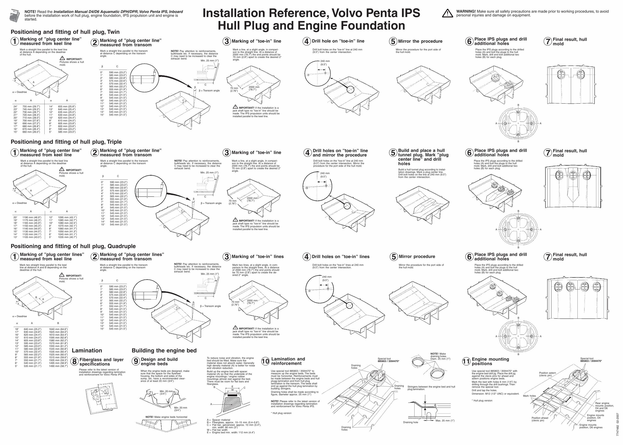
Mark a straight line parallel to the keel lineat distance A depending on the deadriseof the hull.
Mark a straight line parallel to the transomat distance C depending on the transomangle.
α A α A
24° 755 mm (29.7’’) 14° 655 mm (25.8’’)23° 745 mm (29.3’’) 13° 645 mm (25.4’’)22° 730 mm (28.7’’) 12° 635 mm (25.0’’)21° 720 mm (28.3’’) 11° 630 mm (24.8’’)20° 710 mm (28.0’’) 10° 620 mm (24.4’’)19° 700 mm (27.6’’) 9° 610 mm (24.0’’)18° 690 mm (27.2’’) 8° 605 mm (23.8’’)17° 680 mm (26.8’’) 7° 600 mm (23.6’’)16° 670 mm (26.4’’) 6° 590 mm (23.2’’)15° 660 mm (26.0’’) 5° 585 mm (23.0’’)
α A α A
20° 1190 mm (46.9’’) 12° 1095 mm (43.1’’)19° 1175 mm (46.3’’) 11° 1085 mm (42.7’’)18° 1165 mm (45.9’’) 10° 1080 mm (42.5’’)17° 1150 mm (45.3’’) 9° 1070 mm (42.1’’)16° 1140 mm (44.9’’) 8° 1060 mm (41.7’’)15° 1130 mm (44.5’’) 7° 1050 mm (41.3’’)14° 1120 mm (44.1’’) 6° 1045 mm (41.1’’)13° 1105 mm (43.5’’) 5° 1035 mm (40.7’’)
Mark a straight line parallel to the keel lineat distance A depending on the deadriseof the hull.
Mark a straight line parallel to the transomat distance C depending on the transomangle.
Marking of ”plug center lines”measured from keel line1 Marking of ”plug center lines”
measured from transom2
α A B
18° 640 mm (25.2’’) 1640 mm (64.6’’)17° 630 mm (24.8’’) 1625 mm (64.0’’)16° 620 mm (24.4’’) 1610 mm (63.4’’)15° 610 mm (24.0’’) 1595 mm (62.8’’)14° 605 mm (23.8’’) 1580 mm (62.2’’)13° 595 mm (23.4’’) 1570 mm (61.8’’)12° 585 mm (23.0’’) 1555 mm (61.2’’)11° 580 mm (22.8’’) 1545 mm (60.8’’)10° 570 mm (22.4’’) 1535 mm (60.4’’)9° 565 mm (22.2’’) 1525 mm (60.0’’)8° 555 mm (21.9’’) 1515 mm (59.6’’)7° 550 mm (21.7’’) 1505 mm (59.3’’)6° 540 mm (21.3’’) 1495 mm (58.9’’)5° 535 mm (21.1’’) 1490 mm (58.7’’)
Mark two straight lines parallel to the keelline at distance A and B depending on thedeadrise of the hull.
Mark a straight line parallel to the transomat distance C depending on the transomangle.
Use special tool 885803 / 3594470* tomeasure up the engine beds. The bedsmust be horizontal. Reinforcements mustbe made between the engine beds and hullplugg lamination and from hull pluglamination to the transom. The beds shallend up against the hull plug lamination bybuilding stringers.Draining holes shall be made according tofigure, diameter approx. 25 mm (1”)
NOTE! Please refer to the latest version ofinstallation drawings regarding laminationand reinforcement for Volvo Penta IPS.
* Hull plug version
When the engine beds are designed, makesure that the space for the flywheelhousing, the bottom and sides of thesump, etc. have a recommended clear-ance of at least 20 mm (3/4”).
Use special tool 885803 / 3594470* withthe engine bed drill jig. Place the drill jigagainst the clevis pins for ahead andastern positions engine beds.Mark the bed with holes 6 mm (1/4”) bydrilling through the drill bushings. Thenremove the special tool.Drill and tap the holes.Dimension: M12 (1/2” UNC) or equivalent.
* Hull plug version
NOTE! Make engine beds horizontal
To reduce noise and vibration, the enginebed should be filled. Make sure thematerial does not absorb water. Generallyhigh density material (A) is better for noiseand vibration reduction.Build up the engine bed with spacermaterial (A) so that the underside of theengine mountings / engine rubbermountings almost rest against the bed.There must be room for flat bars andfiberglass.
A = Spacer materialB = Fiberglass, approx. 10–15 mm (0.4–0.6")C = Flat bar, galvanized, approx. 10 mm (0.4"),
min. width: 80 mm (3")W = Flat bar widthE = Engine bed min. width: 112 mm (4.4")
Drainingholes
Drainingholes
Drainingholes
Special tool885803 / 3594470*
Min. 20 mm(3/4”)
Min. 20 mm(3/4”)
A
B C
•
•
EW
Design and buildengine beds9 Lamination and
reinforcement10 Engine mountingpositions11
Stringers between the engine bed and hullplug lamination:
Max. 25 mm (1”)Draining hole
Mark holes
Position ahead(clevis pin)
Position astern(clevis pin)
Special tool885803 / 3594470*
Engine mountsposition, D4engines
Engine mountsposition, D6 engines
Rear enginemounts position,D4 and D6engines
NOTE! Makedraining holes.Diam. 25 mm (1”)Fiberglass and layer
specifications8Please refer to the latest version ofinstallation drawings regarding laminationand reinforcement for Volvo Penta IPS.
Lamination
NOTE! Pay attention to reinforcements,bulkheads etc. If necessary, the distanceC may need to be increased to clear theexhaust bend.
NOTE! Pay attention to reinforcements,bulkheads etc. If necessary, the distanceC may need to be increased to clear theexhaust bend.
NOTE! Pay attention to reinforcements,bulkheads etc. If necessary, the distanceC may need to be increased to clear theexhaust bend.
Marking of ”toe-in” line3
70 mm(2.76’’)
Mark a line, at a slight angle, in compari-son to the straight line. At a distance of2000 mm (78.7”) the end points should be70 mm (2.8”) apart to create the desired 2°angle.
2000 mm(78.7’’)
70 mm(2.76’’)
Marking of ”toe-in” lines3Mark two lines, at a slight angle, in com-parison to the straight lines. At a distanceof 2000 mm (78.7”) the end points shouldbe 70 mm (2.8”) apart to create the de-sired 2° angle.
2000 mm(78.7’’)
Drill hole on ”toe-in” line4Drill bolt holes on the “toe-in” line at 240 mm(9.5”) from the center intersection.
240 mm(9.5’’)
Drill holes on ”toe-in” lineand mirror the procedure4
240 mm(9.5’’)
Drill bolt holes on the “toe-in” line at 240 mm(9.5”) from the center intersection. Mirror theprocedure for the port side of the hull mold.
240 mm(9.5’’)
Drill holes on ”toe-in” lines4Drill bolt holes on the “toe-in” lines at 240 mm(9.5”) from the center intersection.
Mirror the procedure5Mirror the procedure for the port side ofthe hull mold.
Build and place a hulltunnel plug. Mark ”plugcenter line” and drillholes
5
Build a hull tunnel plug according to instal-lation drawings. Mark a plug center line.Drill bolt holes on the line at 240 mm (9.5”)from the center intersection.
Mirror procedure5Mirror the procedure for the port side ofthe hull mold.
Place IPS plugs and drilladditional holes6Place the IPS plugs according to the drilledholes (A) and bolt the plugs to the hullmold. Mark, drill and bolt additional twoholes (B) for each plug.
Place IPS plugs and drilladditional holes6Place the IPS plugs according to the drilledholes (A) and bolt the plugs to the hullmold. Mark, drill and bolt additional twoholes (B) for each plug.
Place IPS plugs and drilladditional holes6Place the IPS plugs according to the drilledholes (A) and bolt the plugs to the hullmold. Mark, drill and bolt additional twoholes (B) for each plug.
Final result, hullmold7
Final result, hullmold7
Final result, hullmold7
β C
0° 590 mm (23.2’’)1° 585 mm (23.0’’)2° 580 mm (22.8’’)3° 575 mm (22.6’’)4° 570 mm (22.4’’)5° 565 mm (22.2’’)6° 555 mm (21.9’’)7° 550 mm (21.7’’)8° 545 mm (21.5’’)9° 545 mm (21.5’’)10° 545 mm (21.5’’)11° 545 mm (21.5’’)12° 545 mm (21.5’’)13° 545 mm (21.5’’)14° 545 mm (21.5’’)15° 545 mm (21.5’’)
β C
0° 590 mm (23.2’’)1° 585 mm (23.0’’)2° 580 mm (22.8’’)3° 575 mm (22.6’’)4° 570 mm (22.4’’)5° 565 mm (22.2’’)6° 555 mm (21.9’’)7° 550 mm (21.7’’)8° 545 mm (21.5’’)9° 545 mm (21.5’’)10° 545 mm (21.5’’)11° 545 mm (21.5’’)12° 545 mm (21.5’’)13° 545 mm (21.5’’)14° 545 mm (21.5’’)15° 545 mm (21.5’’)
β C
0° 590 mm (23.2’’)1° 585 mm (23.0’’)2° 580 mm (22.8’’)3° 575 mm (22.6’’)4° 570 mm (22.4’’)5° 565 mm (22.2’’)6° 555 mm (21.9’’)7° 550 mm (21.7’’)8° 545 mm (21.5’’)9° 545 mm (21.5’’)10° 545 mm (21.5’’)11° 545 mm (21.5’’)12° 545 mm (21.5’’)13° 545 mm (21.5’’)14° 545 mm (21.5’’)15° 545 mm (21.5’’)
A
B
B
A
A
B
B
A
A
B
B
A
Min. 25 mm (1”)
C
Min. 25 mm (1”)
C
Min. 25 mm (1”)
C
NOTE! Read the Installation Manual D4/D6 Aquamatic DPH/DPR, Volvo Penta IPS, Inboardbefore the installation work of hull plug, engine foundation, IPS propulsion unit and engine isstarted.
WARNING! Make sure all safety precautions are made prior to working procedures, to avoidpersonal injuries and damage on equipment.
IMPORTANT! If the installation is ajack shaft type no ”toe-in” line should bemade. The IPS propulsion units should beinstalled parallel to the keel line.
2000 mm(78.7’’)70 mm
(2.76’’)
Marking of ”toe-in” line3Mark a line, at a slight angle, in compari-son to the straight line. At a distance of2000 mm (78.7”) the end points should be70 mm (2.8”) apart to create the desired 2°angle.
IMPORTANT! If the installation is ajack shaft type no ”toe-in” line should bemade. The IPS propulsion units should beinstalled parallel to the keel line.
IMPORTANT! If the installation is ajack shaft type no ”toe-in” line should bemade. The IPS propulsion units should beinstalled parallel to the keel line.
IMPORTANT!Pictures shows a hullmold.
IMPORTANT!Pictures shows a hullmold.
IMPORTANT!Pictures shows a hullmold.