Improved Algorithms of Direct Torque Control Methodhomepage1.canvas.ne.jp/sparerib/DTC_ISSN.pdf ·...
11
Andrzej Sikorski, Marek Korzeniewski Improved Algorithms of Direct Torque Control Method DOI UDK IFAC 10.7305/automatika.54-2.173 [681.532.5:621.313.333]:519.254 2.1.4; 1.1.6 Original scientific paper In the paper a new way of DTC control method analysis to explain flux and current distortion at a low speed of motor operation is discussed. As a result, a new DTC-δ algorithm is proposed. It is important that the DTC-δ algorithm uses the same switching table as the DTC method. The modified DTC algorithms are free from the disadvantages of the conventional DTC method i.e. hexagonal flux and strongly deformed current at a low speed range. The dynamical properties of the new algorithms are similar to the conventional DTC method. The correctness of the proposed methods has been confirmed by laboratory investigations. Key words: Direct torque control (DTC), Induction motor drives, Variable-speed drives Unaprije eni algoritmi za izravno upravljanje momentom. Ovaj se rad bavi novim naˇ cinom analize izravnog upravljanja momentom (DTC) radi objašnjenja distorzije toka i struje na malim brzinama vrtnje motora. Kao rezultat, predložen je novi DTC-δ algoritam. Pritom je znaˇ cajno da novi DTC-δ algoritam koristi istu tablicu prekapˇ canja kao i DTC metoda. Modificirani DTC algoritmi su bez nedostataka karakteristiˇ cnih za konvencionalne DTC metode, poput heksagonalnog toka i izrazito izobliˇ cene struje pri niskim brzinama. Dinamiˇ cka svojstva novih algoritama su sliˇ cna konvencionalnoj DTC metodi. Predložene metode su potvr ene laboratorijskim ispitivanjima. Kljuˇ cne rijeˇ ci: izravno upravljanje momentom (DTC), elektromotorni pogoni s kaveznim strojem, pogoni s prom- jenjivom brzinom vrtnje 1 INTRODUCTION The method of direct flux and torque control with a switching table (DTC-ST) proposed by Takahashi and Noguchi [1] in 1985 has been used and developed up to now. In the literature on the subject the following prob- lems have been discussed: - hexagonal flux vector trajectory and distorted stator current at low motor speed, - motor start-up problems e.g. no possibility of motor “excitation” at the torque set value equal zero, - variable switching frequency, - variable torque pulsations. Modifications of control algorithms are limited because of a limited number of voltage output vectors created by a two level inverter (6 active and 2 zero vectors). Thus, an improvement of one property leads to the deteriora- tion of others. A characteristic feature of the conventional DTC-ST method is that in the steady state three vectors are used (two active and zero vectors) just as in the stan- dard PWM. The only difference lies in the fact that in the standard PWM the switching processes occur in a deter- mined sequence, while in the DTC-ST method, the se- quence depends on torque and flux errors. As a result the DTC method should ensure both the minimization of pul- sation as well as the switching frequency. These features are needed to improve the drive’s technical properties by decreasing speed pulsations and also economical proper- ties by reducing switching frequency which affects power dissipation and inverter efficiency. The main way to im- prove the DTC method involves the torque pulsation de- crease keeping the sampling time t p and transistors switch- ing frequency unchanged [2, 3]. Constant switching fre- quency is useful when passive filters are applied on the in- verter output. The above is carried out in two ways. One method consists in the use of adequate torque and flux con- troller structures (using linear controllers) which, in the final stage, take advantage of space voltage modulation. These algorithms are called DTC-SVM [4, 5, 6], due to the fact that the used torque and flux PI controllers, have a longer response time to the torque step changes, although Online ISSN 1848-3380, Print ISSN 0005-1144 ATKAFF 54(2), 188–198(2013) 188 AUTOMATIKA 54(2013) 2, 188–198
Transcript of Improved Algorithms of Direct Torque Control Methodhomepage1.canvas.ne.jp/sparerib/DTC_ISSN.pdf ·...
Andrzej Sikorski, Marek Korzeniewski
Improved Algorithms of Direct Torque Control Method
DOIUDKIFAC
10.7305/automatika.54-2.173[681.532.5:621.313.333]:519.2542.1.4; 1.1.6
Original scientific paper
In the paper a new way of DTC control method analysis to explain flux and current distortion at a low speedof motor operation is discussed. As a result, a new DTC-δ algorithm is proposed. It is important that the DTC-δalgorithm uses the same switching table as the DTC method. The modified DTC algorithms are free from thedisadvantages of the conventional DTC method i.e. hexagonal flux and strongly deformed current at a low speedrange. The dynamical properties of the new algorithms are similar to the conventional DTC method. The correctnessof the proposed methods has been confirmed by laboratory investigations.
Key words: Direct torque control (DTC), Induction motor drives, Variable-speed drives
Unaprije�eni algoritmi za izravno upravljanje momentom. Ovaj se rad bavi novim nacinom analize izravnogupravljanja momentom (DTC) radi objašnjenja distorzije toka i struje na malim brzinama vrtnje motora. Kaorezultat, predložen je novi DTC-δ algoritam. Pritom je znacajno da novi DTC-δ algoritam koristi istu tablicuprekapcanja kao i DTC metoda. Modificirani DTC algoritmi su bez nedostataka karakteristicnih za konvencionalneDTC metode, poput heksagonalnog toka i izrazito izoblicene struje pri niskim brzinama. Dinamicka svojstva novihalgoritama su slicna konvencionalnoj DTC metodi. Predložene metode su potvr�ene laboratorijskim ispitivanjima.
Kljucne rijeci: izravno upravljanje momentom (DTC), elektromotorni pogoni s kaveznim strojem, pogoni s prom-jenjivom brzinom vrtnje
1 INTRODUCTION
The method of direct flux and torque control witha switching table (DTC-ST) proposed by Takahashi andNoguchi [1] in 1985 has been used and developed up tonow. In the literature on the subject the following prob-lems have been discussed:
- hexagonal flux vector trajectory and distorted statorcurrent at low motor speed,
- motor start-up problems e.g. no possibility of motor“excitation” at the torque set value equal zero,
- variable switching frequency,
- variable torque pulsations.
Modifications of control algorithms are limited becauseof a limited number of voltage output vectors created bya two level inverter (6 active and 2 zero vectors). Thus,an improvement of one property leads to the deteriora-tion of others. A characteristic feature of the conventionalDTC-ST method is that in the steady state three vectors
are used (two active and zero vectors) just as in the stan-dard PWM. The only difference lies in the fact that in thestandard PWM the switching processes occur in a deter-mined sequence, while in the DTC-ST method, the se-quence depends on torque and flux errors. As a result theDTC method should ensure both the minimization of pul-sation as well as the switching frequency. These featuresare needed to improve the drive’s technical properties bydecreasing speed pulsations and also economical proper-ties by reducing switching frequency which affects powerdissipation and inverter efficiency. The main way to im-prove the DTC method involves the torque pulsation de-crease keeping the sampling time tp and transistors switch-ing frequency unchanged [2, 3]. Constant switching fre-quency is useful when passive filters are applied on the in-verter output. The above is carried out in two ways. Onemethod consists in the use of adequate torque and flux con-troller structures (using linear controllers) which, in thefinal stage, take advantage of space voltage modulation.These algorithms are called DTC-SVM [4, 5, 6], due tothe fact that the used torque and flux PI controllers, have alonger response time to the torque step changes, although
Online ISSN 1848-3380, Print ISSN 0005-1144ATKAFF 54(2), 188–198(2013)
188 AUTOMATIKA 54(2013) 2, 188–198
Improved Algorithms of Direct Torque Control Method A. Sikorski, M. Korzeniewski
the complex controller systems [7] bring their propertiescloser to the DTC method, which applies the nonlinearcontrollers. The other method involves improving the clas-sical conception of the nonlinear (hysteresis) torque andflux controllers by an introduction of additional modula-tion algorithms at sampling time tp [8, 9, 10]. For thispurpose additional triangular signals modulating the torqueand flux errors are used to decrease pulsations simulta-neously increasing the inverter switching frequency. Themost advanced algorithms use different level complicationpredictive controllers [11, 12]. Predictive algorithms re-quire the knowledge of motor parameters that can be bestidentified on-line. The algorithms are sensitive to param-eter changes. Prediction includes accurate calculations ofcontrolled parameters (flux and torque) [13] as well as de-termination of their values in one or several steps ahead[14, 15, 16].
A better chance of solving DTC-ST problems is of-fered by multi-level converters, in which a higher numberof voltage vectors enable realization of different control al-gorithms [17].
Frequently, mistakes are made when comparing differ-ent algorithms with the DTC-ST standard algorithm an-alyzing the torque pulsations as the comparisons disre-gard the average inverter switching frequency. For exam-ple, some compare the DTC-SVM method torque pulsa-tion at the same sampling time to the DTC method thatuses nonlinear controllers (comparators). It should be keptin mind that during one sampling period tp the nonlin-ear controller evokes one voltage vector change, while inDTC-SVM method the PWM modulator evokes six volt-age vector changes. Therefore, it is difficult to expecthigher torque pulsation in the DTC-SVM method. To beable to compare the pulsations the DTC-ST sampling timetp should be six times shorter. Obviously, the speed-uprequires a faster and more expensive processor [18].
In this paper problems of the hexagonal flux trajectoryand current deformations at low motor speed [19, 20] andmotor start-up are discussed. Generally, these problemscan be solved by predictive algorithms and DTC-SVM (us-ing PWM) algorithms. However, simpler algorithms simi-lar to DTC-ST fail to eliminate these disadvantages. Some-times mistakes in the creation of algorithms unexpectedlyeliminate flux and current distortions in some special con-ditions. The flux estimation method has a significant effecton the quality of control [6, 21]. It can be shown that awrong flux estimation resulting in the significant flux phaseshift at low speed in some particular cases moves sectorborder N in such a way that flux and current deformationsdo not occur at low motor speed. It resembles a part of thealgorithm described in section IV. Another mistake is nar-rowing down of the torque hysteresis at level dT = 0. Asa result, at low motor speed and large torque error values
eT , dT signal take the values of 1 or −1 and a zero vectoris not used for dT = 0 (Table I).
Table 1: Switching table for the DTC method.
The analysis of the DTC-ST method has been usuallycarried out basing on the motor torque equation as a prod-uct of stator ψs and rotor ψr fluxes and the angle betweenthem as well as the dependence of the stator flux on theinverter output voltage vectors [1, 4]. The analysis is usu-ally carried out in the stationary coordinates αβ. Suchan approach, although correct, does not always allow usto notice and to clarify the inconveniences and shortcom-ings of the DTC method. The author’s investigations inthe area of analysis and synthesis of the current controlledmethods proposed in [22] were used to analyze the DTCmethod. Although in the DTC method the current com-ponents are not controlled directly, interesting conclusionscan be drawn concerning the influence of the current com-ponents phenomena on the torque and flux values in theDTC method. In the paper analysis of the DTC operation(section III) and also the causes of the current and flux de-formation at the low motor speed (section 3.1), are pre-sented.
2 DTC-ST METHOD
The DTC method proposed by Takahashi and Noguchiis based on a direct control of the stator flux and torque.The scheme of the control system is shown in Fig. 1. Thestator flux ψs and electromagnetic torque T set values (thespeed controller output signal) are compared with real val-ues ψs and T and passed to the nonlinear controllers (com-parators).
The inverter optimal states placed in address memoryare selected by a two-level flux comparator and a three-level torque comparator depending on sector N (π/3) inwhich the flux vector is situated. The angle ϕs between thestator flux vector ψs and α axis in stationary coordinatesαβ is determined by equation: ϕs = arctg (ψsβ/ψsβ).Particular inverter transistor states (converter output volt-age vectors) depending on the comparison results of theset and real values of torque and flux and current sector Nof flux vector positions are listed in Table I.
AUTOMATIKA 54(2013) 2, 188–198 189
Improved Algorithms of Direct Torque Control Method A. Sikorski, M. Korzeniewski
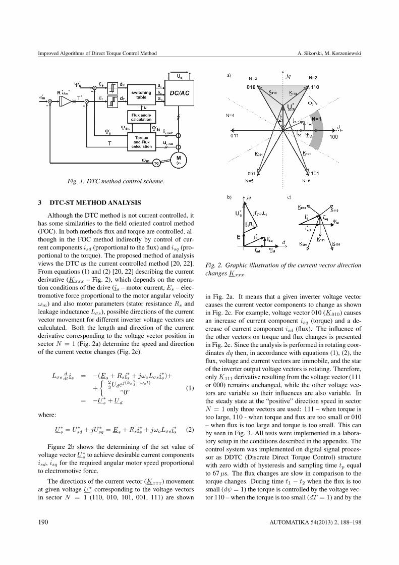
Fig. 1. DTC method control scheme.
3 DTC-ST METHOD ANALYSIS
Although the DTC method is not current controlled, ithas some similarities to the field oriented control method(FOC). In both methods flux and torque are controlled, al-though in the FOC method indirectly by control of cur-rent components isd (proportional to the flux) and isq (pro-portional to the torque). The proposed method of analysisviews the DTC as the current controlled method [20, 22].From equations (1) and (2) [20, 22] describing the currentderivative (Kxxx – Fig. 2), which depends on the opera-tion conditions of the drive (is – motor current, Es – elec-tromotive force proportional to the motor angular velocityωm) and also motor parameters (stator resistance Rs andleakage inductance Lσs), possible directions of the currentvector movement for different inverter voltage vectors arecalculated. Both the length and direction of the currentderivative corresponding to the voltage vector position insector N = 1 (Fig. 2a) determine the speed and directionof the current vector changes (Fig. 2c).
Lσsddt is = −(Es +Rsi
∗s + jωoLσsi
∗s)+
+
{23Ude
j(ks23−ωot)
”0”= −U∗s + Ud
(1)
where:
U∗s = U∗sd + jU∗sq = Es +Rsi∗s + jωoLσsi
∗s (2)
Figure 2b shows the determining of the set value ofvoltage vector U∗s to achieve desirable current componentsisd, isq for the required angular motor speed proportionalto electromotive force.
The directions of the current vector (Kxxx) movementat given voltage U∗s corresponding to the voltage vectorsin sector N = 1 (110, 010, 101, 001, 111) are shown
Fig. 2. Graphic illustration of the current vector directionchanges Kxxx.
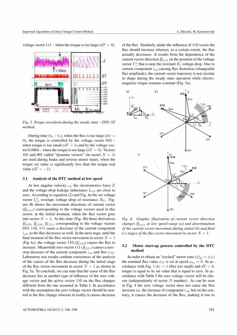
in Fig. 2a. It means that a given inverter voltage vectorcauses the current vector components to change as shownin Fig. 2c. For example, voltage vector 010 (K010) causesan increase of current component isq (torque) and a de-crease of current component isd (flux). The influence ofthe other vectors on torque and flux changes is presentedin Fig. 2c. Since the analysis is performed in rotating coor-dinates dq then, in accordance with equations (1), (2), theflux, voltage and current vectors are immobile, and the starof the inverter output voltage vectors is rotating. Therefore,onlyK111 derivative resulting from the voltage vector (111or 000) remains unchanged, while the other voltage vec-tors are variable so their influences are also variable. Inthe steady state at the “positive” direction speed in sectorN = 1 only three vectors are used: 111 – when torque istoo large, 110 - when torque and flux are too small or 010– when flux is too large and torque is too small. This canby seen in Fig. 3. All tests were implemented in a labora-tory setup in the conditions described in the appendix. Thecontrol system was implemented on digital signal proces-sor as DDTC (Discrete Direct Torque Control) structurewith zero width of hysteresis and sampling time tp equalto 67µs. The flux changes are slow in comparison to thetorque changes. During time t1 − t2 when the flux is toosmall (dψ = 1) the torque is controlled by the voltage vec-tor 110 – when the torque is too small (dT = 1) and by the
190 AUTOMATIKA 54(2013) 2, 188–198
Improved Algorithms of Direct Torque Control Method A. Sikorski, M. Korzeniewski
voltage vector 111 – when the torque is too large (dT = 0).
Fig. 3. Torque waveform during the steady state – DTC-STmethod.
During time (t0− t1), when the flux is too large (dψ =0), the torque is controlled by the voltage vector 010 –when torque is too small (dT = 1) and by the voltage vec-tor 0 (000) – when the torque is too large (dT = 0). Vectors101 and 001 called ”dynamic vectors” (in sector N = 1)are used during brake and reverse motor states, when thetorque set value is significantly less than the torque realvalue (dT = −1).
3.1 Analysis of the DTC method at low speed
At low angular velocity ωo the electromotive force Eand the voltage drop leakage inductance LσS are close tozero. According to equation (2) and Fig. 4a the set voltagevector U∗S overlaps voltage drop of resistance RS . Fig-ure 4b shows the movement directions of current vector(Kxxx) corresponding to the voltage vectors used in thissector, at the initial moment, when the flux vector goesinto sector N = 1. At this time (Fig. 4b) three derivativesK010, K110, K111, corresponding to the voltage vectors010, 110, 111 cause a decrease of the current componentisd, so the flux decreases as well. In the next stage, until thefinal moment of the flux vector movement in sector N = 1(Fig 4c), the voltage vector 110 (K110) causes the flux toincrease. Meanwhile zero vector 111 (K111) causes a non -stop decrease of the current component isd and flux ψM .Laboratory test results confirm correctness of the analysisof the causes of the flux decrease during the initial stageof the flux vector movement in sector N = 1 as shown inFig. 5a. To conclude, we can state that the cause of the fluxdecrease lies in another type of influence of the zero volt-age vector and the active vector 110 on the flux changesdifferent from the one assumed in Table I. In accordancewith the assumption the zero voltage vector should be neu-tral to the flux change whereas in reality it causes decrease
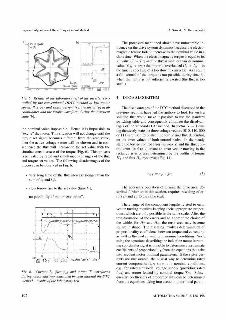
of the flux. Similarly, under the influence of 110 vector theflux should increase whereas, to a certain extent, the fluxactually decreases. It results from the dependence of thecurrent vector directionK111 on the position of the voltagevector U∗s that is near the resistantRs voltage drop. Due tocurrent component isd causing flux distortion (changeableflux amplitude), the current vector trajectory is not circularin shape during the steady state operation while electro-magnetic torque remains constant (Fig. 5a).
Fig. 4. Graphic illustration of current vector directionchanges Kxxx at low speed range (a) and determinationof the current vector movement during initial (b) and final(c) stages of the flux vector movement in sector N = 1.
3.2 Motor start-up process controlled by the DTCmethod
In order to obtain an “excited” motor state (ψ∗M = ψN )the nominal flux value ψN is set at speed ωm = 0. In ac-cordance with Fig. 1 dψ = 1 (flux too small) and dT = 0,torque is equal to its set value that is equal to zero. In ac-cordance with Table I the zero voltage vector will be cho-sen (independently of sector N number). As can be seenin Fig. 4 the zero voltage vector does not cause the fluxincrease i.e. the increase of component isd, but on the con-trary, it causes the decrease of the flux, making it rise to
AUTOMATIKA 54(2013) 2, 188–198 191
Improved Algorithms of Direct Torque Control Method A. Sikorski, M. Korzeniewski
Fig. 5. Results of the laboratory test of the inverter con-trolled by the conventional DDTC method at low motorspeed: flux ψM and stator current is trajectories (a) in abcoordinates and the torque waveform during the transientstate (b).
the nominal value impossible. Hence it is impossible to“excite” the motor. This situation will not change until thetorque set signal becomes different from the zero value,then the active voltage vector will be chosen and in con-sequence the flux will increase to the set value with thesimultaneous increase of the torque (Fig. 6). This processis activated by rapid and simultaneous changes of the fluxand torque set values. The following disadvantages of theprocess can be observed in Fig. 6:
- very long time of the flux increase (longer than thesum of t1 and t2),
- slow torque rise to the set value (time t1),
- no possibility of motor “excitation”.
Fig. 6. Current Is, flux ψM and torque T waveformsduring motor start-up controlled by conventional the DTCmethod – results of the laboratory test.
The processes mentioned above have unfavorable in-fluence on the drive system dynamics because the electro-magnetic torque fails to increase to the nominal value in ashort time. When the electromagnetic torque is equal to itsset value (T = T ∗) and the flux is smaller than its nominalvalue (ψM < ψN ) the motor is overloaded (Is > IN – inthe time t2) because of a too slow flux increase. As a resulta full control of the torque is not possible during time t1,when the motor is not sufficiently excited (the flux is toosmall).
4 DTC-δ ALGORITHM
The disadvantages of the DTC method discussed in theprevious sections have led the authors to look for such asolution that would make it possible to use the standardswitching table and consequently eliminate the disadvan-tages of the standard DTC method. In sector N = 1 dur-ing the steady state the three voltage vectors (010, 110, 000or 111) are used to control the torque and flux dependingon the error values of both control paths. In the steadystate the torque control error (in q-axis) and the flux con-trol error (in δ-axis) create an error vector moving in therectangular error area determined by the widths of torqueHT and flux Hψ hysteresis (Fig. 11).
εψT = εψ + jεT (3)
The necessary operation of turning the error area, de-scribed further on in this section, requires rescaling of er-rors εT and εψ to the same scale.
The change of the component lengths related to errorvector turning requires keeping their appropriate propor-tions, which are only possible in the same scale. After thetransformation of the errors and an appropriate choice ofthe widths for HT and Hψ , the error area may becomesquare in shape. The rescaling involves determination ofproportionality coefficients between torque and current cTas well as flux and current cψ in nominal conditions. Next,using the equations describing the induction motor in rotat-ing coordinates dq, it is possible to determine approximatecoefficients of proportionality from the equations that takeinto account motor nominal parameters. If the stator cur-rents are measurable, the easiest way to determine ratedcurrent components isqN isdN is in nominal conditions,e.g. for rated sinusoidal voltage supply (providing ratedflux) and motor loaded by nominal torque TN . Subse-quently, coefficients of proportionality can be determinedfrom the equations taking into account motor rated param-
192 AUTOMATIKA 54(2013) 2, 188–198
Improved Algorithms of Direct Torque Control Method A. Sikorski, M. Korzeniewski
eters or from approximated equations:
cψ =isdNψmN
∼= isdNLmisdN
=1
Lm(4)
cT =isqNTN
=isqN
pb32ψsdN isqN
=2
3pbψsdN∼= 2ωoN
3pbUN√2(5)
where: isqN , isdN – components of the rated stator cur-rent vector in the dq coordinate, respectively proportionalto nominal motor torque TN and flux ψsdN at the nominalvoltage UN characterized by angular frequency ωoN . Therescaled torque and flux error vector can be expressed bythe following equation:
εiψT = εψcψ + jεT cT = εiψ + jεiT (6)
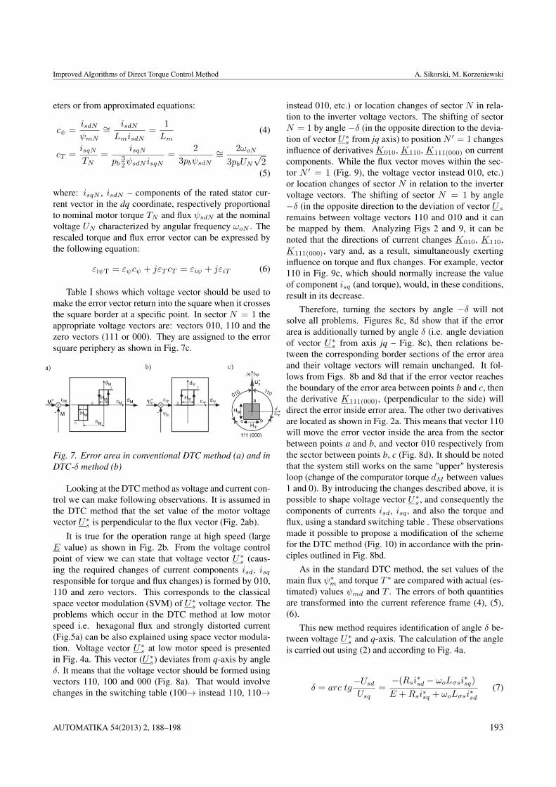
Table I shows which voltage vector should be used tomake the error vector return into the square when it crossesthe square border at a specific point. In sector N = 1 theappropriate voltage vectors are: vectors 010, 110 and thezero vectors (111 or 000). They are assigned to the errorsquare periphery as shown in Fig. 7c.
Fig. 7. Error area in conventional DTC method (a) and inDTC-δ method (b)
Looking at the DTC method as voltage and current con-trol we can make following observations. It is assumed inthe DTC method that the set value of the motor voltagevector U∗s is perpendicular to the flux vector (Fig. 2ab).
It is true for the operation range at high speed (largeE value) as shown in Fig. 2b. From the voltage controlpoint of view we can state that voltage vector U∗s (caus-ing the required changes of current components isd, isqresponsible for torque and flux changes) is formed by 010,110 and zero vectors. This corresponds to the classicalspace vector modulation (SVM) of U∗s voltage vector. Theproblems which occur in the DTC method at low motorspeed i.e. hexagonal flux and strongly distorted current(Fig.5a) can be also explained using space vector modula-tion. Voltage vector U∗s at low motor speed is presentedin Fig. 4a. This vector (U∗s) deviates from q-axis by angleδ. It means that the voltage vector should be formed usingvectors 110, 100 and 000 (Fig. 8a). That would involvechanges in the switching table (100→ instead 110, 110→
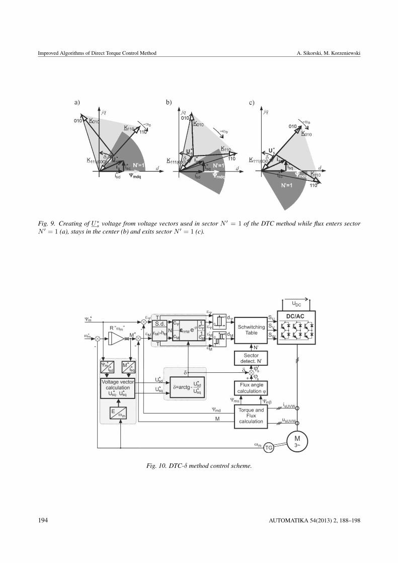
instead 010, etc.) or location changes of sector N in rela-tion to the inverter voltage vectors. The shifting of sectorN = 1 by angle −δ (in the opposite direction to the devia-tion of vector U∗s from jq axis) to position N ′ = 1 changesinfluence of derivatives K010, K110, K111(000) on currentcomponents. While the flux vector moves within the sec-tor N ′ = 1 (Fig. 9), the voltage vector instead 010, etc.)or location changes of sector N in relation to the invertervoltage vectors. The shifting of sector N = 1 by angle−δ (in the opposite direction to the deviation of vector Usremains between voltage vectors 110 and 010 and it canbe mapped by them. Analyzing Figs 2 and 9, it can benoted that the directions of current changes K010, K110,K111(000), vary and, as a result, simultaneously exertinginfluence on torque and flux changes. For example, vector110 in Fig. 9c, which should normally increase the valueof component isq (and torque), would, in these conditions,result in its decrease.
Therefore, turning the sectors by angle −δ will notsolve all problems. Figures 8c, 8d show that if the errorarea is additionally turned by angle δ (i.e. angle deviationof vector U∗s from axis jq – Fig. 8c), then relations be-tween the corresponding border sections of the error areaand their voltage vectors will remain unchanged. It fol-lows from Figs. 8b and 8d that if the error vector reachesthe boundary of the error area between points b and c, thenthe derivative K111(000), (perpendicular to the side) willdirect the error inside error area. The other two derivativesare located as shown in Fig. 2a. This means that vector 110will move the error vector inside the area from the sectorbetween points a and b, and vector 010 respectively fromthe sector between points b, c (Fig. 8d). It should be notedthat the system still works on the same "upper" hysteresisloop (change of the comparator torque dM between values1 and 0). By introducing the changes described above, it ispossible to shape voltage vector U∗s , and consequently thecomponents of currents isd, isq , and also the torque andflux, using a standard switching table . These observationsmade it possible to propose a modification of the schemefor the DTC method (Fig. 10) in accordance with the prin-ciples outlined in Fig. 8bd.
As in the standard DTC method, the set values of themain flux ψ∗m and torque T ∗ are compared with actual (es-timated) values ψmd and T . The errors of both quantitiesare transformed into the current reference frame (4), (5),(6).
This new method requires identification of angle δ be-tween voltage U∗s and q-axis. The calculation of the angleis carried out using (2) and according to Fig. 4a.
δ = arc tg−UsdUsq
=−(Rsi∗sd − ωoLσsi∗sq)E +Rsi∗sq + ωoLσsi∗sd
(7)
AUTOMATIKA 54(2013) 2, 188–198 193
Improved Algorithms of Direct Torque Control Method A. Sikorski, M. Korzeniewski
Fig. 9. Creating of U∗s voltage from voltage vectors used in sector N ′ = 1 of the DTC method while flux enters sectorN ′ = 1 (a), stays in the center (b) and exits sector N ′ = 1 (c).
Fig. 10. DTC-δ method control scheme.
194 AUTOMATIKA 54(2013) 2, 188–198
Improved Algorithms of Direct Torque Control Method A. Sikorski, M. Korzeniewski
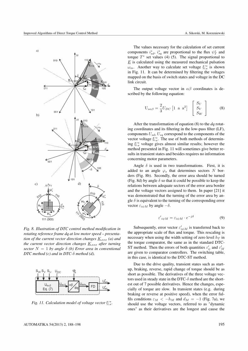
Fig. 8. Illustration of DTC control method modification inrotating reference frame dq at low motor speed – presenta-tion of the current vector direction changes Kxxx (a) andthe current vector direction changes Kxxx after turningsector N = 1 by angle δ (b) Error area in conventionalDTC method (c) and in DTC-δ method (d).
Fig. 11. Calculation model of voltage vector U∗s .
The values necessary for the calculation of set currentcomponents i∗sd, i∗sq are proportional to the flux ψ∗T andtorque T ∗ set values (4) (5). The signal proportional toE is calculated using the measured mechanical pulsationωm. Another way to calculate set voltage U∗s is shownin Fig. 11. It can be determined by filtering the voltagesmapped on the basis of switch states and voltage in the DClink circuit.
The output voltage vector in αβ coordinates is de-scribed by the following equation:
Usαβ =2
3UDC
[1 a a2
]SUSVSW
(8)
After the transformation of equation (8) to the dq rotat-ing coordinates and its filtering in the low-pass filter (LF),components Usd, Usq correspond to the components of thevector voltage U∗s . The use of both methods of determin-ing U∗s voltage gives almost similar results; however themethod presented in Fig. 11 will sometimes give better re-sults in transient states and besides requires no informationconcerning motor parameters.
Angle δ is used in two transformations. First, it isadded to an angle ϕs that determines sectors N bor-ders (Fig. 8b). Secondly, the error area should be turned(Fig. 8d) by angle δ so that it could be possible to keep therelations between adequate sectors of the error area borderand the voltage vectors assigned to them. In paper [21] itwas demonstrated that the turning of the error area by an-gle δ is equivalent to the turning of the corresponding errorvector εiψM by angle −δ.
ε′iψM = εiψM · e−jδ (9)
Subsequently, error vector ε′iψM is transferred back tothe appropriate scale of flux and torque. This rescaling isnecessary when using the width setting of zero level hT inthe torque comparator, the same as in the standard DTC-ST method. Then the errors of both quantities ε′ψ and ε′Mare given to comparator controllers. The switching table,in this case, is identical to the DTC-ST method.
Due to the drive quality, transient states such as start-up, braking, reverse, rapid change of torque should be asshort as possible. The derivatives of the three voltage vec-tors used in steady state in the DTC-δ method are the short-est out of 7 possible derivatives. Hence the changes, espe-cially of torque are slow. In transient states (e.g. duringbraking or reverse at positive speed), when the error ful-fils conditions εM < −hM and dM = −1 (Fig. 7a), weshould use the voltage vectors, referred to as "dynamicones" as their derivatives are the longest and cause the
AUTOMATIKA 54(2013) 2, 188–198 195
Improved Algorithms of Direct Torque Control Method A. Sikorski, M. Korzeniewski
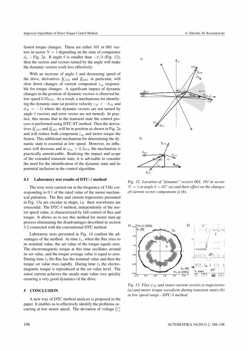
fastest torque changes. These are either 101 or 001 vec-tors in sector N = 1 depending on the state of comparatordψ – Fig. 2a. If angle δ is smaller than −π/3 (Fig. 12),then the sectors and vectors turned by the angle will makethe dynamic vectors work less effectively.
With an increase of angle δ and decreasing speed ofthe drive, derivatives K101 and K001 in particular, willslow down changes of current component isq responsi-ble for torque changes. A significant impact of dynamicchanges in the position of dynamic vectors is observed be-low speed 0.05ωN . As a result, a mechanisms for identify-ing the dynamic state (at positive velocity εM < −hM anddM = −1) where the dynamic vectors are not turned byangle δ (sectors and error vector are not turned). In prac-tice, this means that in the transient state the control pro-cess is performed using DTC-ST method. Then the deriva-tivesK101 andK001 will be in position as shown in Fig. 2aand will reduce both component isq and motor torque thefastest. This additional mechanism for determining the dy-namic state is essential at low speed. However, its influ-ence will decrease and at ωm > 0.2ωN the mechanism ispractically unnoticeable. Realizing the impact and scopeof the extended transient state, it is advisable to considerthe need for the identification of the dynamic state and itspotential inclusion in the control algorithm.
4.1 Laboratory test results of DTC-δ method
The tests were carried out at the frequency of 5 Hz cor-responding to 0.1 of the rated value of the motor mechan-ical pulsation. The flux and current trajectories presentedin Fig. 13a are circular in shape, i.e. their waveforms aresinusoidal. The DTC-δ method, independently of the mo-tor speed value, is characterized by full control of flux andtorque. It allows us to use this method for motor start-upprocess eliminating the disadvantages described in section3.2 connected with the conventional DTC method.
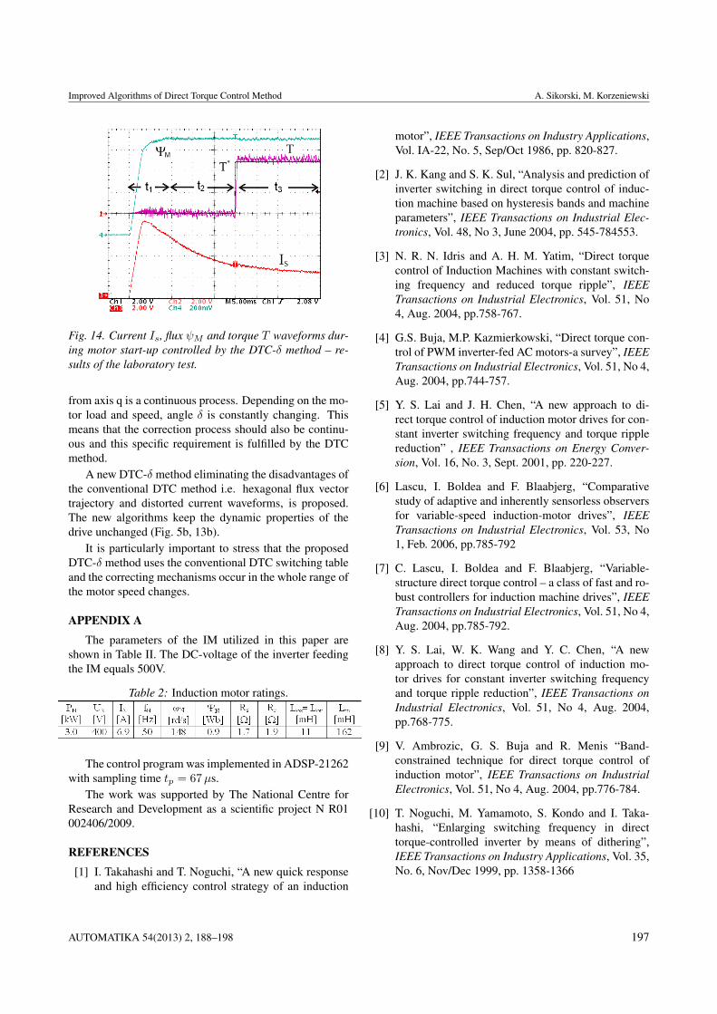
Laboratory tests presented in Fig. 14 confirm the ad-vantages of the method. At time t1, when the flux rises toits nominal value, the set value of the torque equals zero.The electromagnetic torque at this time oscillates aroundits set value, and the torque average value is equal to zero.During time t2 the flux has the nominal value and then thetorque set value rises rapidly. During time t3 the electro-magnetic torque is reproduced at the set value level. Thestator current achieves the steady-state value very quicklyensuring a very good dynamics of the drive.
5 CONCLUSION
A new way of DTC method analysis is proposed in thepaper. It enables us to effectively identify the problems oc-curring at low motor speed. The deviation of voltage U∗s
Fig. 12. Location of "dynamic" vectors 001, 101 in sectorN = 1 at angle δ = 65◦ (a) and their effect on the changesof current vector components is (b).
Fig. 13. Flux ψM and stator current vectors is trajectories(a) and motor torque waveform during transient states (b)at low speed range - DTC-δ method.
196 AUTOMATIKA 54(2013) 2, 188–198
Improved Algorithms of Direct Torque Control Method A. Sikorski, M. Korzeniewski
Fig. 14. Current Is, flux ψM and torque T waveforms dur-ing motor start-up controlled by the DTC-δ method – re-sults of the laboratory test.
from axis q is a continuous process. Depending on the mo-tor load and speed, angle δ is constantly changing. Thismeans that the correction process should also be continu-ous and this specific requirement is fulfilled by the DTCmethod.
A new DTC-δ method eliminating the disadvantages ofthe conventional DTC method i.e. hexagonal flux vectortrajectory and distorted current waveforms, is proposed.The new algorithms keep the dynamic properties of thedrive unchanged (Fig. 5b, 13b).
It is particularly important to stress that the proposedDTC-δ method uses the conventional DTC switching tableand the correcting mechanisms occur in the whole range ofthe motor speed changes.
APPENDIX AThe parameters of the IM utilized in this paper are
shown in Table II. The DC-voltage of the inverter feedingthe IM equals 500V.
Table 2: Induction motor ratings.
The control program was implemented in ADSP-21262with sampling time tp = 67µs.
The work was supported by The National Centre forResearch and Development as a scientific project N R01002406/2009.
REFERENCES[1] I. Takahashi and T. Noguchi, “A new quick response
and high efficiency control strategy of an induction
motor”, IEEE Transactions on Industry Applications,Vol. IA-22, No. 5, Sep/Oct 1986, pp. 820-827.
[2] J. K. Kang and S. K. Sul, “Analysis and prediction ofinverter switching in direct torque control of induc-tion machine based on hysteresis bands and machineparameters”, IEEE Transactions on Industrial Elec-tronics, Vol. 48, No 3, June 2004, pp. 545-784553.
[3] N. R. N. Idris and A. H. M. Yatim, “Direct torquecontrol of Induction Machines with constant switch-ing frequency and reduced torque ripple”, IEEETransactions on Industrial Electronics, Vol. 51, No4, Aug. 2004, pp.758-767.
[4] G.S. Buja, M.P. Kazmierkowski, “Direct torque con-trol of PWM inverter-fed AC motors-a survey”, IEEETransactions on Industrial Electronics, Vol. 51, No 4,Aug. 2004, pp.744-757.
[5] Y. S. Lai and J. H. Chen, “A new approach to di-rect torque control of induction motor drives for con-stant inverter switching frequency and torque ripplereduction” , IEEE Transactions on Energy Conver-sion, Vol. 16, No. 3, Sept. 2001, pp. 220-227.
[6] Lascu, I. Boldea and F. Blaabjerg, “Comparativestudy of adaptive and inherently sensorless observersfor variable-speed induction-motor drives”, IEEETransactions on Industrial Electronics, Vol. 53, No1, Feb. 2006, pp.785-792
[7] C. Lascu, I. Boldea and F. Blaabjerg, “Variable-structure direct torque control – a class of fast and ro-bust controllers for induction machine drives”, IEEETransactions on Industrial Electronics, Vol. 51, No 4,Aug. 2004, pp.785-792.
[8] Y. S. Lai, W. K. Wang and Y. C. Chen, “A newapproach to direct torque control of induction mo-tor drives for constant inverter switching frequencyand torque ripple reduction”, IEEE Transactions onIndustrial Electronics, Vol. 51, No 4, Aug. 2004,pp.768-775.
[9] V. Ambrozic, G. S. Buja and R. Menis “Band-constrained technique for direct torque control ofinduction motor”, IEEE Transactions on IndustrialElectronics, Vol. 51, No 4, Aug. 2004, pp.776-784.
[10] T. Noguchi, M. Yamamoto, S. Kondo and I. Taka-hashi, “Enlarging switching frequency in directtorque-controlled inverter by means of dithering”,IEEE Transactions on Industry Applications, Vol. 35,No. 6, Nov/Dec 1999, pp. 1358-1366
AUTOMATIKA 54(2013) 2, 188–198 197
Improved Algorithms of Direct Torque Control Method A. Sikorski, M. Korzeniewski
[11] T. G. Habetler, F. Profumo, M. Pastorelli, and L. M.Tolbert, “Direct torque control of induction machinesusing space vector modulation”, IEEE Transactionson Industry Applications, Vol. 28, No. 5, Sep/Oct1992, pp. 1045-1053.
[12] M. Bertoluzzo, G. Buja,and R. Menis, “Direct Torquecontrol of an induction motor using a single currentsensor”, IEEE Transactions on Industrial Electron-ics, Vol. 53, No. 3, June 2006, pp. 778-784.
[13] J. Beerten, J. Verveckken, J. Driesen, “Predictive di-rect torque control for flux and torque ripple reduc-tion”, IEEE Trans. Ind. Electron., vol. 57, no. 1, Jan.2009,pp. 404-412.
[14] H. Miranda, P. Cortés, J. Yuz, and J. Rodríguez, “Pre-dictive torque control of induction machines based onstate space models,” IEEE Trans. Ind. Electron., vol.56, no. 6, pp. 1916–1924, Jun. 2009.
[15] T. Geyer, G. Papafotiou, and M. Morari, “Model pre-dictive direct torque control—Part I: Concept, algo-rithm and analysis,” IEEE Trans. Ind. Electron., vol.56, no. 6, Jun. 2009 pp., 1894–1905.
[16] G. Papafotiou, J. Kley, K. Papdopoulos, P. Bohren,and M. Morari, “Modelpredictive direct torquecontrol—Part II: Implementation and experimentalevaluation,” IEEE Trans. Ind. Electron., vol. 56, no.6, Jun. 2009, pp. 1906–1915.
[17] D. Casadei, G. Serra and A. Tani, “Implementation ofa direct torque control algorithm for induction motorsbased on discrete space vector modulation”, IEEETransactions on Power Electronics, Vol. 15, No 4,July 2000, pp. 769-777.
[18] J. N. Nash, “Direct torque control induction mo-tor vector control without an encoder”, IEEE Trans-actions on Industry Applications, Vol. 33, Mar/Apr1997, pp. 333-341.
[19] M. P. Kazmierkowski and A. B. Kasprowicz, “Im-proved direct torque and flux vector control of PWMinverter-fed induction motor drives”, IEEE Transac-tions on Industrial Electronics, Vol. 42, No 4, Aug.1995, pp.344-350
[20] Sikorski A., Korzeniewski M.: Improved directtorque and flux control of induction motor drive,COMPEL, Vol. 26, Nr 4, 2007, s. 1204-1217.
[21] J. Holtz„”Sensorless control of induction machines –with or without signal injection? IEEE Transactionson Industrial Electronics, Vol. 53, No. 1, Feb 2006,pp. 7-30.
[22] A. Sikorski and T. Citko, “Current controller reducedswitching frequency for VS-PWM inverter used withAC motor drive application”, IEEE Transactions onIndustrial Electronics, Vol. 45, No. 5, Oct. 1998, pp.792-801.
Andrzej Sikorski received the M.S. degree inelectrical engineering from the Bialystok Tech-nical University, Bialystok, Poland, in 1980 andthe Ph.D. degree in electrical engineering fromthe Warsaw University of Technology, Warsaw,Poland, in 1989. In 1989, he became an AssistantProfessor and, in 2000, he became an AssociateProfessor at the Faculty of Electrical Engineeringof the Bialystok Technical University, Bialystok,Poland. His research interests are in the areas ofpower electronics, particularly AC/DC/AC soft-
switching converters and in the control of electrical drives, control ofpower converters and PWM. He has published more than 80 papers intechnical journals and conference proceedings.
Marek Korzeniewski was born in Pisz, PolandIn 1975. He received the M.S. degree in elec-trical engineering, in 2001, and the Ph.D. degreein electrical engineering in 2009 from the Bia-lystok Technical University, Bialystok, Poland.In 2001 he became an Assistant professor andsince 2010 he is Lecturer at the Bialystok Uni-versity of Technology, Faculty of Electrical En-gineering. His research interests are in the areasof power electronics systems, digital control sys-tems run by DSP processors and programmable
devices CPLD / FPGA. He has published close to 40 papers in technicaljournals and conference proceedings.
AUTHORS’ ADDRESSESProf. Andrzej Sikorski, Ph.D.Marek Korzeniewski, Ph.D.Depertment of Power Electronics and ElectricalDriversBialystok University of Technology45D Wiejska St.15-351 Bialystok, Polandemail: [email protected],[email protected]
Received: 2012-01-19Accepted: 2012-06-27
198 AUTOMATIKA 54(2013) 2, 188–198