Hitachi Yutaki Series 2016 Αντλίες θερμότητας
256
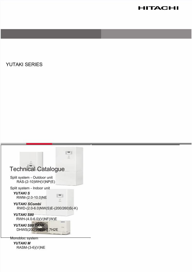
YUTAKI SERIES Split system - Outdoor unit RAS-(2-10)WH(V)NP(E) Split system - Indoor unit YUTAKI S RWM-(2.0-10.0)NE YUTAKI SCombi RWD-(2.0-6.0)NW(S)E-(200/260)S(-K) YUTAKI S80 RWH-(4.0-6.0)(V)NF(W)E YUTAKI S80 TANK DHWS(200/260)S-2.7H2E Monobloc system YUTAKI M RASM-(3-6)(V)NE Technical Catalogue
Transcript of Hitachi Yutaki Series 2016 Αντλίες θερμότητας
8/16/2019 Hitachi Yutaki Series 2016 Αντλίες θερμότητας
http://slidepdf.com/reader/full/hitachi-yutaki-series-2016- 1/256

8/16/2019 Hitachi Yutaki Series 2016 Αντλίες θερμότητας
http://slidepdf.com/reader/full/hitachi-yutaki-series-2016- 2/256
8/16/2019 Hitachi Yutaki Series 2016 Αντλίες θερμότητας
http://slidepdf.com/reader/full/hitachi-yutaki-series-2016- 3/256
Contents
TCGB0098 rev.0 - 04/2016III
1
2
3
4
5
6
7
8
9
10
11
Contents
General information
Features and benefts
General data
Capacity and selection data
Acoustic characteristic curves
Working range
General dimensions
Refrigerant cycle and hydraulic circuit
Refrigerant and water piping
Electrical and control settings
Optional functions

8/16/2019 Hitachi Yutaki Series 2016 Αντλίες θερμότητας
http://slidepdf.com/reader/full/hitachi-yutaki-series-2016- 4/256
8/16/2019 Hitachi Yutaki Series 2016 Αντλίες θερμότητας
http://slidepdf.com/reader/full/hitachi-yutaki-series-2016- 5/256
General Index
TCGB0098 rev.0 - 04/2016V
General Index
1. General information ................................................................................................... 1
1.1 General information ................................................................................................................................. 2
1.1.1 General notes .................................................................................................................................................. 2
1.1.2 Introduction ..................................................................................................................................................... 2
1.1.2.1 Overview of YUTAKI system .............................................................................................................. 2
1.1.2.2 Summary of operations ...................................................................................................................... 3
1.2 Applied symbols ...................................................................................................................................... 5
1.3 Product guide .......................................................................................................................................... 6
1.3.1 Classication of the units ................................................................................................................................. 6
1.3.1.1 Split system - Outdoor unit ................................................................................................................. 6
1.3.1.2 Split system - Indoor unit .................................................................................................................... 6
1.3.1.3 Monobloc system ............................................................................................................................... 7
1.3.2 Product guide .................................................................................................................................................. 8
1.3.2.1 Split system - Outdoor unit ................................................................................................................. 8
1.3.2.2 Split system - Indoor unit .................................................................................................................... 8
1.3.2.3 Monobloc system ..............................................................................................................................11
1.3.3 Accessory code list ........................................................................................................................................ 12
2. Features and benefits .............................................................................................. 15
2.1 Selection benets ..................................................................................................................................16
2.1.1 Wide selection range ..................................................................................................................................... 16
2.1.2 High efciency system. Wide capacity range ................................................................................................19
2.1.3 Wide range of accessories and components ................................................................................................19
2.2 Installation benets................................................................................................................................26
2.2.1 YUTAKI S reduced dimensions ..................................................................................................................... 26
2.2.2 YUTAKI S80 improved connections .............................................................................................................. 27
2.3 Maintenance benets ............................................................................................................................28
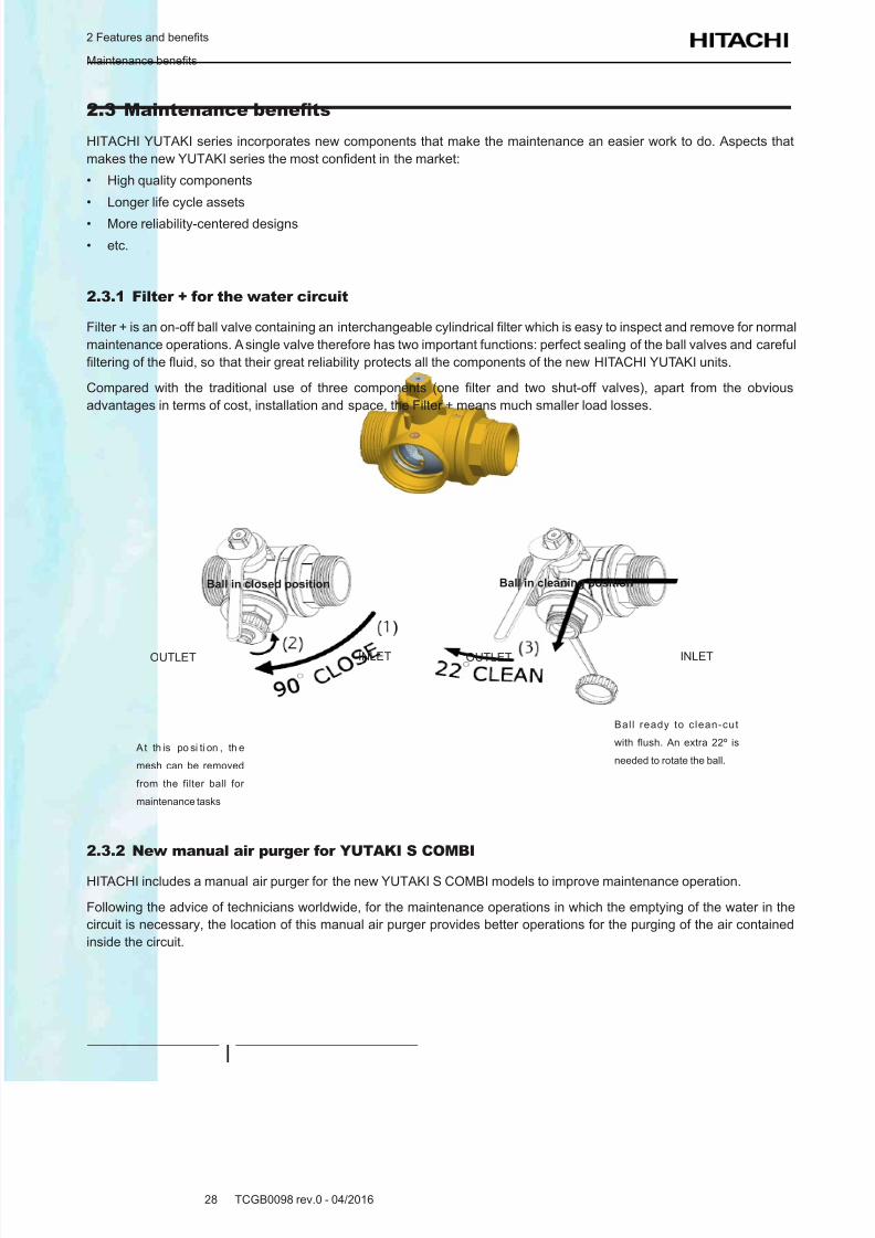
2.3.1 Filter + for the water circuit ............................................................................................................................ 28
2.3.2 New manual air purger for YUTAKI S COMBI ...............................................................................................28
2.4 Control features ..................................................................................................................................... 29
2.4.1 Unit controller: more functions ....................................................................................................................... 29
2.4.2 I/O and sensor functions ............................................................................................................................... 29
3. General data ............................................................................................................. 31
3.1 Capacity tables ...................................................................................................................................... 32
3.1.1 Nominal capacity-performance tables ........................................................................................................... 32
3.1.1.1 Considerations ................................................................................................................................. 32
3.1.1.2 Capacity-performance data .............................................................................................................. 32
8/16/2019 Hitachi Yutaki Series 2016 Αντλίες θερμότητας
http://slidepdf.com/reader/full/hitachi-yutaki-series-2016- 6/256
General Index
TCGB0098 rev.0 - 04/2016VI
3.2 ERP performance data ..........................................................................................................................35
3.2.1 General considerations ................................................................................................................................. 35
3.2.2 General ERP data for space heaters ............................................................................................................ 35
3.2.2.1 ERP data - YUTAKI S .......................................................................................................................35
3.2.2.2 ERP data - YUTAKI S COMBI .......................................................................................................... 413.2.2.3 ERP data - YUTAKI S80 ...................................................................................................................46
3.2.2.4 ERP data - YUTAKI M ......................................................................................................................49
3.2.2.5 ERP additional data - YUTAKI S ......................................................................................................52
3.2.2.6 ERP additional data - YUTAKI S COMBI .........................................................................................53
3.2.2.7 ERP additional data - YUTAKI S80 ..................................................................................................54
3.2.3 General ERP data for combi heaters (YUTAKI S COMBI & S80) ................................................................. 55
3.2.3.1 YUTAKI S COMBI ............................................................................................................................55
3.2.3.2 YUTAKI S80 ..................................................................................................................................... 56
3.2.4 General ERP data for hot water storage tanks (YUTAKI S , YUTAKI M & YUTAKI S 80 RWH-4.0VNFE ..... 56
3.3 General specications ...........................................................................................................................57
3.3.1 Considerations .............................................................................................................................................. 57
3.3.2 Split system - Outdoor unit ............................................................................................................................ 58
3.3.3 Split system - Indoor unit ............................................................................................................................... 60
3.3.3.1 YUTAKI S ......................................................................................................................................... 60
3.3.3.2 YUTAKI S COMBI ............................................................................................................................63
3.3.3.3 YUTAKI S80 ..................................................................................................................................... 69
3.3.4 Monobloc system - YUTAKI M....................................................................................................................... 72
3.3.5 Domestic Hot Water Tank .............................................................................................................................. 74
3.4 Component data .................................................................................................................................... 75
3.4.1 Split system - Outdoor unit ............................................................................................................................ 75
3.4.2 Split system - Indoor unit ............................................................................................................................... 77
3.4.2.1 YUTAKI S ......................................................................................................................................... 77
3.4.2.2 YUTAKI S COMBI ............................................................................................................................78
3.4.2.3 YUTAKI S80 ..................................................................................................................................... 82
3.4.3 Monobloc system - YUTAKI M....................................................................................................................... 83
3.5 Electrical data ........................................................................................................................................ 853.5.1 Considerations .............................................................................................................................................. 85
3.5.2 Split system - Outdoor unit ............................................................................................................................ 86
3.5.3 Split system - Indoor unit ............................................................................................................................... 87
3.5.3.1 YUTAKI S ......................................................................................................................................... 87
3.5.3.2 YUTAKI S COMBI ............................................................................................................................87
3.5.3.3 YUTAKI S80 ..................................................................................................................................... 88
3.5.4 Monobloc system - YUTAKI M....................................................................................................................... 90
4. Capacity and selection data .................................................................................... 914.1 System selection procedure ..................................................................................................................92
4.1.1 Selection parameters .................................................................................................................................... 92
8/16/2019 Hitachi Yutaki Series 2016 Αντλίες θερμότητας
http://slidepdf.com/reader/full/hitachi-yutaki-series-2016- 7/256
General Index
TCGB0098 rev.0 - 04/2016VII
4.1.2 Selection procedure ...................................................................................................................................... 92
4.1.2.1 Description of procedure for YUTAKI S ............................................................................................94
4.1.2.2 Description of procedure for YUTAKI S COMBI ............................................................................. 100
4.1.2.3 Description of procedure for YUTAKI S 80 ..................................................................................... 107
4.1.2.4 Selection procedure for YUTAKI M units .........................................................................................114
4.1.3 Flow rate and pressure drop check ..............................................................................................................119
4.2 System selection procedure (by Selection Software) .......................................................................... 120
4.2.1 Introduction .................................................................................................................................................. 120
4.2.2 How to use the Selection Software ............................................................................................................. 120
4.3 YUTAKI S ............................................................................................................................................ 139
4.3.1 Maximum heating capacity table (kW) (Integrated) ..................................................................................... 139
4.3.2 Maximum cooling capacity table (kW) .........................................................................................................141
4.4 YUTAKI S COMBI ...............................................................................................................................142
4.4.1 Maximum heating capacity table (kW) (Integrated) ..................................................................................... 142
4.4.2 Maximum cooling capacity table (kW) ........................................................................................................144
4.5 YUTAKI S 80 ....................................................................................................................................... 145
4.5.1 Maximum heating capacity table (kW) (Integrated) ..................................................................................... 145
4.6 YUTAKI M ............................................................................................................................................ 146
4.6.1 Maximum heating capacity table (kW) (Integrated) ..................................................................................... 146
4.6.2 Maximum cooling capacity table (kW) ........................................................................................................147
4.7 Correction factors ................................................................................................................................148
4.7.1 Piping length correction factor ..................................................................................................................... 148
4.7.2 Correction factor owing to use of glycol (only for YUTAKI M)...................................................................... 151
5. Acoustic characteristic curves ............................................................................. 153
5.1 Considerations ....................................................................................................................................154
5.2 Sound pressure level for outdoor unit .................................................................................................155
6. Working range ........................................................................................................ 157
6.1 Power supply working range ...............................................................................................................158
6.2 Temperature working range.................................................................................................................158
6.2.1 Space heating ............................................................................................................................................. 158
6.2.2 DHW ............................................................................................................................................................ 160
6.2.3 Swimming pool heating ............................................................................................................................... 161
6.2.4 Space cooling (Necessary cooling kit) ........................................................................................................161
6.3 Hydraulic working range ......................................................................................................................162
6.3.1 Hydraulic data ............................................................................................................................................. 162
6.3.2 Pump performance curves .......................................................................................................................... 163
8/16/2019 Hitachi Yutaki Series 2016 Αντλίες θερμότητας
http://slidepdf.com/reader/full/hitachi-yutaki-series-2016- 8/256
General Index
TCGB0098 rev.0 - 04/2016VIII
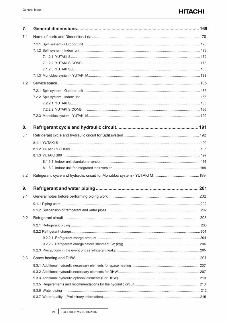
7. General dimensions ............................................................................................... 169
7.1 Name of parts and Dimensional data .................................................................................................. 170
7.1.1 Split system - Outdoor unit .......................................................................................................................... 170
7.1.2 Split system - Indoor unit ............................................................................................................................. 172
7.1.2.1 YUTAKI S ....................................................................................................................................... 172
7.1.2.2 YUTAKI S COMBI ..........................................................................................................................175
7.1.2.3 YUTAKI S80 ................................................................................................................................... 180
7.1.3 Monobloc system - YUTAKI M..................................................................................................................... 183
7.2 Service space ...................................................................................................................................... 185
7.2.1 Split system - Outdoor unit .......................................................................................................................... 185
7.2.2 Split system - Indoor unit ............................................................................................................................. 186
7.2.2.1 YUTAKI S ....................................................................................................................................... 186
7.2.2.2 YUTAKI S COMBI ..........................................................................................................................186
7.2.3 Monobloc system - YUTAKI M..................................................................................................................... 190
8. Refrigerant cycle and hydraulic circuit ................................................................ 191
8.1 Refrigerant cycle and hydraulic circuit for Split system ....................................................................... 192
8.1.1 YUTAKI S .................................................................................................................................................... 192
8.1.2 YUTAKI S COMBI........................................................................................................................................195
8.1.3 YUTAKI S80 ................................................................................................................................................ 197
8.1.3.1 Indoor unit standalone version .......................................................................................................197
8.1.3.2 Indoor unit for integrated tank version ............................................................................................198
8.2 Refrigerant cycle and hydraulic circuit for Monobloc system - YUTAKI M ..........................................199
9. Refrigerant and water piping ................................................................................ 201
9.1 General notes before performing piping work .....................................................................................202
9.1.1 Piping work .................................................................................................................................................. 202
9.1.2 Suspension of refrigerant and water pipes ..................................................................................................202
9.2 Refrigerant circuit ................................................................................................................................ 203
9.2.1 Refrigerant piping ........................................................................................................................................ 203
9.2.2 Refrigerant charge ....................................................................................................................................... 204
9.2.2.1 Refrigerant charge amount ............................................................................................................204
9.2.2.2 Refrigerant charge before shipment (W0 (kg)) ............................................................................... 204
9.2.3 Precautions in the event of gas refrigerant leaks ........................................................................................205
9.3 Space heating and DHW .....................................................................................................................207
9.3.1 Additional hydraulic necessary elements for space heating ........................................................................ 207
9.3.2 Additional hydraulic necessary elements for DHW ......................................................................................207
9.3.3 Additional hydraulic optional elements (For DHW) ......................................................................................210
9.3.5 Requirements and recommendations for the hydraulic circuit .................................................................... 210
9.3.6 Water piping ................................................................................................................................................ 212
9.3.7 Water quality (Preliminary information) .....................................................................................................215
8/16/2019 Hitachi Yutaki Series 2016 Αντλίες θερμότητας
http://slidepdf.com/reader/full/hitachi-yutaki-series-2016- 9/256
General Index
TCGB0098 rev.0 - 04/2016IX
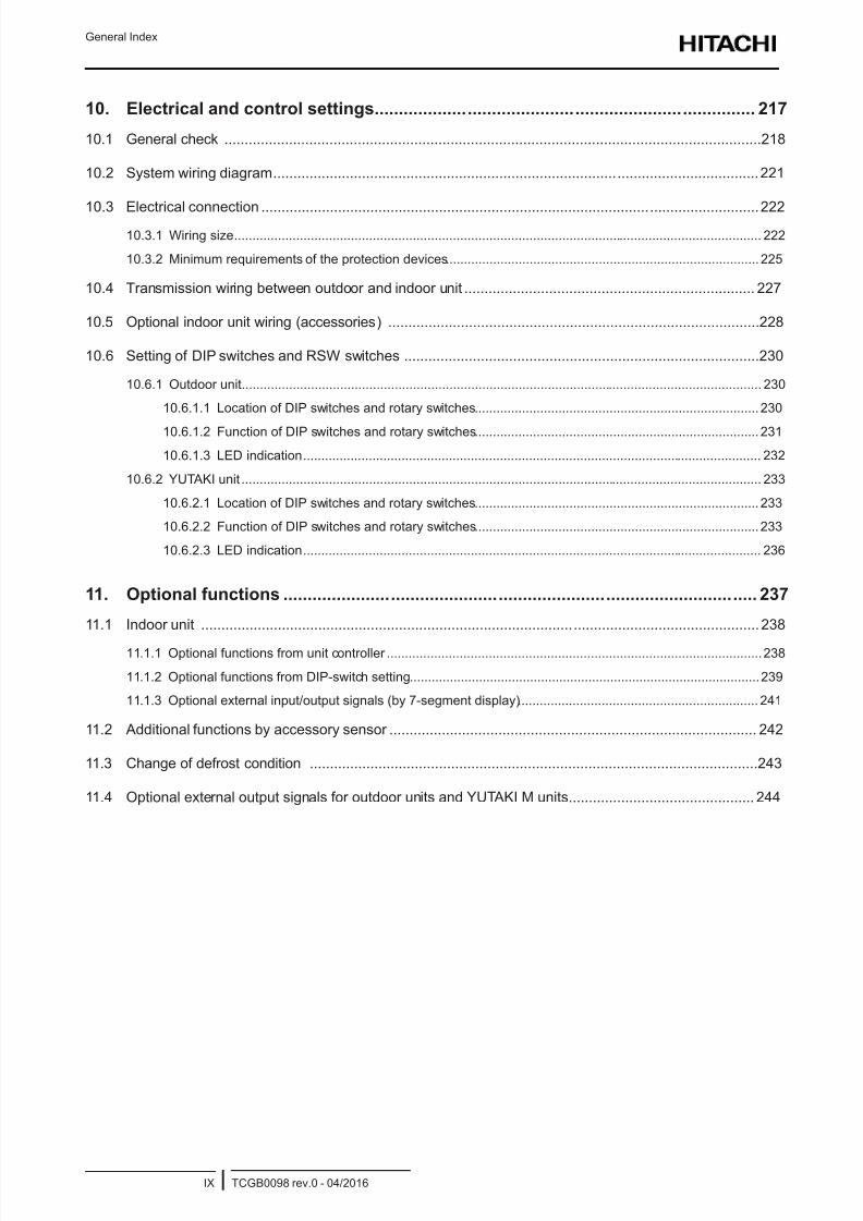
10. Electrical and control settings .............................................................................. 217
10.1 General check .....................................................................................................................................218
10.2 System wiring diagram ........................................................................................................................221
10.3 Electrical connection ...........................................................................................................................22210.3.1 Wiring size ................................................................................................................................................. 222
10.3.2 Minimum requirements of the protection devices ...................................................................................... 225
10.4 Transmission wiring between outdoor and indoor unit ........................................................................ 227
10.5 Optional indoor unit wiring (accessories) ............................................................................................228
10.6 Setting of DIP switches and RSW switches ........................................................................................230
10.6.1 Outdoor unit ............................................................................................................................................... 230
10.6.1.1 Location of DIP switches and rotary switches .............................................................................. 230
10.6.1.2 Function of DIP switches and rotary switches .............................................................................. 231
10.6.1.3 LED indication .............................................................................................................................. 232
10.6.2 YUTAKI unit ............................................................................................................................................... 233
10.6.2.1 Location of DIP switches and rotary switches .............................................................................. 233
10.6.2.2 Function of DIP switches and rotary switches .............................................................................. 233
10.6.2.3 LED indication .............................................................................................................................. 236
11. Optional functions ................................................................................................. 237
11.1 Indoor unit .......................................................................................................................................... 238
11.1.1 Optional functions from unit controller .......................................................................................................238
11.1.2 Optional functions from DIP-switch setting ................................................................................................239
11.1.3 Optional external input/output signals (by 7-segment display) .................................................................. 241
11.2 Additional functions by accessory sensor ........................................................................................... 242
11.3 Change of defrost condition ...............................................................................................................243
11.4 Optional external output signals for outdoor units and YUTAKI M units .............................................. 244

8/16/2019 Hitachi Yutaki Series 2016 Αντλίες θερμότητας
http://slidepdf.com/reader/full/hitachi-yutaki-series-2016- 10/256
8/16/2019 Hitachi Yutaki Series 2016 Αντλίες θερμότητας
http://slidepdf.com/reader/full/hitachi-yutaki-series-2016- 11/256
1 General information
TCGB0098 rev.0 - 04/20161
1
Index
1.1 General information ................................................................................................................................. 2
1.1.1 General notes .................................................................................................................................................. 2
1.1.2 Introduction ..................................................................................................................................................... 2
1.1.2.1 Overview of YUTAKI system ...........................................................................................................2
1.1.2.2 Summary of operations ................................................................................................................... 3
1.2 Applied symbols ...................................................................................................................................... 5
1.3 Product guide .......................................................................................................................................... 6
1.3.1 Classication of the units ................................................................................................................................. 6
1.3.1.1 Split system - Outdoor unit .............................................................................................................6
1.3.1.2 Split system - Indoor unit ................................................................................................................ 6
1.3.1.3 Monobloc system ............................................................................................................................ 7
1.3.2 Product guide .................................................................................................................................................. 8
1.3.2.1 Split system - Outdoor unit .............................................................................................................8
1.3.2.2 Split system - Indoor unit ................................................................................................................ 8
1.3.2.3 Monobloc system ...........................................................................................................................11
1.3.3 Accessory code list ........................................................................................................................................ 12
1 . G e n e r a l i n f o r m a t i o n
8/16/2019 Hitachi Yutaki Series 2016 Αντλίες θερμότητας
http://slidepdf.com/reader/full/hitachi-yutaki-series-2016- 12/256
1 General information
General information
TCGB0098 rev.0 - 04/20162
1.1 General information
1.1.1 General notes
© Copyright 2016 HITACHI Air Conditioning Products Europe, S.A.U. – All rights reserved.
No part of this publication may be reproduced, copied, led or transmitted in any shape or form without the permission of
HITACHI Air Conditioning Products Europe, S.A.U.
Within the policy of continuous improvement of its products, HITACHI Air Conditioning Products Europe, S.A.U. reserves
the right to make changes at any time without prior notication and without being compelled to introducing them into
previously sold products. This document may therefore have been subject to amendments during the life of the product.
HITACHI makes every effort to offer correct, up-to-date documentation. Despite this, printing errors cannot be controlled by
HITACHI and are not its responsibility.
As a result, some of the images or data used to illustrate this document may not refer to specic models. No claims will be
accepted based on the data, illustrations and descriptions included in this manual.
No type of modication must be made to the equipment without prior, written authorization from the manufacturer.
N O T E
This air conditioner has been designed for standard air conditioning for human beings. For use in other applications,
please contact your HITACHI dealer or service contractor.
1.1.2 Introduction
HITACHI proudly announces the newest complete range of air-to-water heat pumps in its award-winning YUTAKI range.
YUTAKI units produce heating and domestic hot water like any oil or gas boiler, but transforming renewable energy from
the outside air into heat. Air to water heat pumps extract the free energy present in the air, which is enough to heat a home
up to a comfortable temperature, even on the coldest winter day. Every kW of electricity used to power the heat pump can
yield up to more than 5 kW of energy for heating; this provides savings of up to 80% on heating expenses compared to a
traditional fossil fuel boiler.
The new YUTAKI series, based on state-of-the-art technology, does not only achieve an outstanding performance in space
heating, but it is also provides domestic hot water with high efciency. Additionally, cooling operation for summer can also
be provided installing the dedicated “Cooling kit” accessory of HITACHI.
The system is simple to control; its new user controller (PC-ARFHE) improves the acclaimed and successful design used
with the existing LCD controller, and provides a great deal of new functions like: wizard start-up conguration, auto cool/
heat, improved timer, etc.
1.1.2.1 Overview of YUTAKI system
The wide range of YUTAKI products is basically divided in two types of system:
• Split system
• Monobloc system
Split system - YUTAKI S, YUTAKI S COMBI, YUTAKI S80
It consists of one outdoor unit and one indoor unit. The outdoor unit extracts the heat present in the air, increases its refrig-
erant temperature and transmits it to the water circuit using the plate heat exchanger of the indoor unit, where the heat is
taken to radiators (fan-coils), underoor heating components or both (2nd temperature area).
Three types of indoor unit can be used in heating split systems:
YUTAKI S
The indoor unit of YUTAKI S is designed for space heating, in wall-mounted installation. It is convenient for new installa-
tions with low capacity requirements (Well isolated installations, high efciency radiators...).
8/16/2019 Hitachi Yutaki Series 2016 Αντλίες θερμότητας
http://slidepdf.com/reader/full/hitachi-yutaki-series-2016- 13/256
1 General information
General information
TCGB0098 rev.0 - 04/20163
1
YUTAKI S COMBI
The indoor unit of YUTAKI S COMBI is conceived as a oor standing unit. It is prepared for heating operation as well as
for domestic hot water production. For this purpose, it has a built-in domestic hot water tank available in two sizes (200 or
260 L). In line with YUTAKI S units, it meets the needs of installations with low capacity requirements.
Furthermore, special YUTAKI S COMBI models have been designed with a specic solar tank for the use of solar panels.
Also, new models for the UK market that meet the UK requirements refferred in the UK Building Regulations.
YUTAKI S80
The YUTAKI S80 is a standalone indoor unit that generates hot water up to 80ºC; the hottest water temperature in the
domestic heating market using renewable energy.
The extra innovation in the YUTAKI S80 lies in that it has two compressors, working in a smart cascade system, with two
refrigerant cycles (R-410A and R-134a). To maximize seasonal efciency, the second refrigerant cycle is only operated as
a booster, when very high water temperature is required - the rest of the time, only one cycle is used.
The YUTAKI S80 is ideal for existing properties, in particular older installations where high water supply temperatures may
be required to keep the house warm – as well as for new buildings. It is designed for the replacement of boilers, offering
heating and sanitary hot water all year round, without boiler back-up.
Two different models have been designed for different purposes: one model for space heating only and the other one forspace heating as well as for DHW operation. For DHW operation (optional), HITACHI offers two specic YUTAKI S80 DHW
tanks (DHWS200S-2.7H2E and DHWS260S-2.7H2E) which may be placed on top of the indoor unit or besides it, as an
integrated unit to provide high-temperature domestic hot water enjoying the benets of the high efciency of the heat pump.
Monobloc system - YUTAKI M
YUTAKI M is a monobloc air to water heat pump system composed by only an special outdoor unit, which carries out the
function of an air-to-water heat pump. This results in an excellent solution when installation space available is limited.
YUTAKI M is designed to be installed outdoors, in any kind of dwelling (house, apartment, villa,…), whether in a new con-
struction or in an existing building. Installation work is greatly simplied thanks to the lack of refrigerant piping connections.
1.1.2.2 Summary of operations
Space heating
YUTAKI units are factory-supplied ready for space heating operation. Different heating installation congurations can be
selected, providing a comfortable atmosphere all year long, even in the coldest climates:
• Mono-valent system
The air to water heat pump is sized to provide 100% of the heating requirements on the coldest day the year.
• Mono-energy system
This is the most popular conguration. The air to water heat pump is sized to provide 80% of the heating
requirements on the coldest days of the year. An auxiliary electric heater is used to provide the additional heating
required on cold days. This option usually results in an ideal balance between installation costs and future energy
consumption, as proven by its popularity in colder climates than ours, such as Sweden and Norway.
• Alternating Bi-valent system
For installations with an existing heating system by boiler and when is needed to heat the supplied water temperature
to the circuit up to high temperatures (80ºC), the boiler can be congured to alternate with the air to water heat pump.
Selecting the different conguration types it is possible to adapt the system to all customer requirements, providing a wide
application range from the simplest conguration to complete conguration: Radiator, heating oor or both (2nd tempera-
ture area).
Domestic hot water production
YUTAKI models also give the option of domestic hot water production, allowing the user to benet from the heat pump’s
high efciency and achieve domestic hot water.
This is made possible by a domestic hot water tank. In case of YUTAKI S COMBI, the domestic hot water tank is built in
the indoor unit. In YUTAKI S80, a specic DHW tank is designed for combination with the indoor unit. For YUTAKI S andYUTAKI M, the HITACHI accessory “DHWT-(200/260)S-3.0H2E” can be used for the production of DHW.
An electric heater is incorporated inside the tank in order to allow an inmediate heating of the domestic hot water in ac-
cordance with the user’s needs.
8/16/2019 Hitachi Yutaki Series 2016 Αντλίες θερμότητας
http://slidepdf.com/reader/full/hitachi-yutaki-series-2016- 14/256
1 General information
General information
TCGB0098 rev.0 - 04/20164
Space cooling
YUTAKI units can also be operated in cooling operation The dedicated “Cooling kit” accessory has been designed for this
purpose. Combining the heating only models with these cooling kits, the reversible models become available. In this case,
combination with fan-coils, refreshing oor or both (2nd temperature area) can be applied.
Combination with solar panels
YUTAKI system can be combined with solar panel. The solar combination enables to heat up the DHW by means of the
sun. The solar combination is designed to transfer the heat from the solar panels (sun radiation) to the heat exchanger of
DHW tank.
In case of YUTAKI S COMBI, a specic model with integrated tank for solar combination has been designed, as explained
before.
Swimming pool water heating operation
For summer session period, YUTAKI system can be used to heat up the water temperature of swimming pools up to a value
between 24 and 33ºC.
8/16/2019 Hitachi Yutaki Series 2016 Αντλίες θερμότητας
http://slidepdf.com/reader/full/hitachi-yutaki-series-2016- 15/256
1 General information
Applied symbols
TCGB0098 rev.0 - 04/20165
1
1.2 Applied symbols
During normal air conditioning system design work or unit installation, greater attention must be paid in certain situations
requiring particular care in order to avoid damage to the unit, the installation or the building or property.
Situations that pose a risk to the safety of those in the surrounding area or to the unit itself are clearly indicated in this
manual.
A series of special symbols are used to clearly identify these situations.
Pay close attention to these symbols and to the messages following them, as your safety and that of others depends on it.
D A N G E R
• The text following this symbol contains information and instructions relating directly to your safety.
• Not taking these instructions into account could lead to serious, very serious or even fatal injuries to you and
others.
In the texts following the danger symbol you can also nd information on safety procedures during unit installation.
C A U T I O N
• The text following this symbol contains information and instructions relating directly to your safety.• Not taking these instructions into account could lead to minor injuries to you and others.
• Not taking these instructions into account could lead to unit damage.
In the texts following the caution symbol you can also nd information on safety procedures during unit installation.
N O T E
• The text following this symbol contains information or instructions that may be of use or that require a more thorough
explanation.
• Instructions regarding inspections to be made on unit parts or systems may also be included.
8/16/2019 Hitachi Yutaki Series 2016 Αντλίες θερμότητας
http://slidepdf.com/reader/full/hitachi-yutaki-series-2016- 16/256
1 General information
Product guide
TCGB0098 rev.0 - 04/20166
1.3 Product guide
1.3.1 Classication of the units
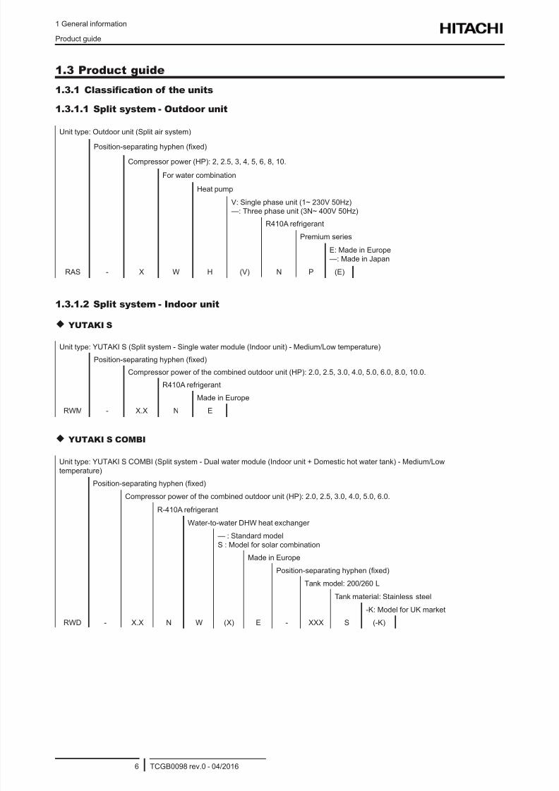
1.3.1.1 Split system - Outdoor unit
Unit type: Outdoor unit (Split air system)
Position-separating hyphen (xed)
Compressor power (HP): 2, 2.5, 3, 4, 5, 6, 8, 10.
For water combination
Heat pump
V: Single phase unit (1~ 230V 50Hz)
—: Three phase unit (3N~ 400V 50Hz)
R410A refrigerant
Premium series
E: Made in Europe
—: Made in Japan
RAS - X W H (V) N P (E)
1.3.1.2 Split system - Indoor unit
YUTAKI S
Unit type: YUTAKI S (Split system - Single water module (Indoor unit) - Medium/Low temperature)
Position-separating hyphen (xed)
Compressor power of the combined outdoor unit (HP): 2.0, 2.5, 3.0, 4.0, 5.0, 6.0, 8.0, 10.0.
R410A refrigerant
Made in Europe
RWM - X.X N E
YUTAKI S COMBI
Unit type: YUTAKI S COMBI (Split system - Dual water module (Indoor unit + Domestic hot water tank) - Medium/Low
temperature)
Position-separating hyphen (xed)
Compressor power of the combined outdoor unit (HP): 2.0, 2.5, 3.0, 4.0, 5.0, 6.0.
R-410A refrigerant
Water-to-water DHW heat exchanger
— : Standard model
S : Model for solar combination
Made in Europe
Position-separating hyphen (xed)
Tank model: 200/260 L
Tank material: Stainless steel
-K: Model for UK market
RWD - X.X N W (X) E - XXX S (-K)
8/16/2019 Hitachi Yutaki Series 2016 Αντλίες θερμότητας
http://slidepdf.com/reader/full/hitachi-yutaki-series-2016- 17/256
1 General information
Product guide
TCGB0098 rev.0 - 04/20167
1
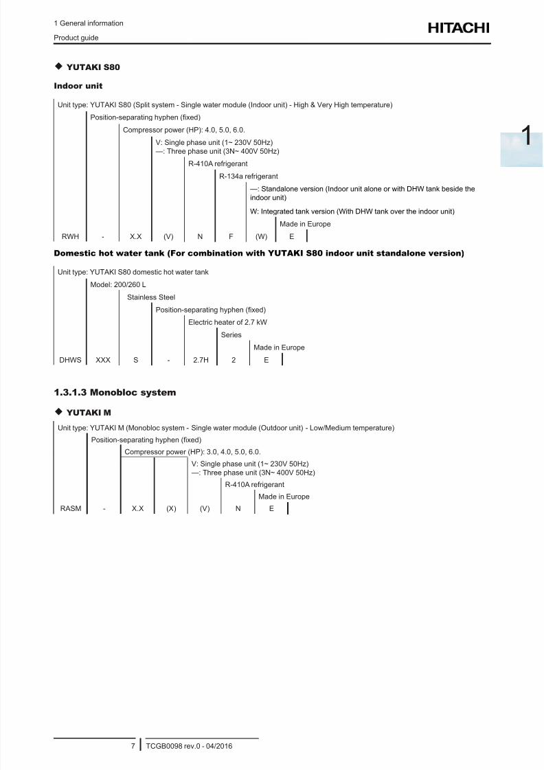
YUTAKI S80
Indoor unit
Unit type: YUTAKI S80 (Split system - Single water module (Indoor unit) - High & Very High temperature)
Position-separating hyphen (xed)
Compressor power (HP): 4.0, 5.0, 6.0.
V: Single phase unit (1~ 230V 50Hz)
—: Three phase unit (3N~ 400V 50Hz)
R-410A refrigerant
R-134a refrigerant
—: Standalone version (Indoor unit alone or with DHW tank beside the
indoor unit)
W: Integrated tank version (With DHW tank over the indoor unit)
Made in Europe
RWH - X.X (V) N F (W) E
Domestic hot water tank (For combination with YUTAKI S80 indoor unit standalone version)
Unit type: YUTAKI S80 domestic hot water tank
Model: 200/260 L
Stainless Steel
Position-separating hyphen (xed)
Electric heater of 2.7 kW
Series
Made in Europe
DHWS XXX S - 2.7H 2 E
1.3.1.3 Monobloc system
YUTAKI M
Unit type: YUTAKI M (Monobloc system - Single water module (Outdoor unit) - Low/Medium temperature)
Position-separating hyphen (xed)
Compressor power (HP): 3.0, 4.0, 5.0, 6.0.
V: Single phase unit (1~ 230V 50Hz)
—: Three phase unit (3N~ 400V 50Hz)
R-410A refrigerant
Made in Europe
RASM - X.X (X) (V) N E

8/16/2019 Hitachi Yutaki Series 2016 Αντλίες θερμότητας
http://slidepdf.com/reader/full/hitachi-yutaki-series-2016- 18/256
1 General information
Product guide
TCGB0098 rev.0 - 04/20168
1.3.2 Product guide
1.3.2.1 Split system - Outdoor unit
1~ 230V 50Hz 3N~ 400V 50Hz
Unit Code Unit Code Unit Code
RAS-2WHVNP 60288672 - - - -RAS-2.5WHVNP 60288673 - - - -
RAS-3WHVNP 60288674 - - - -
- - RAS-4WHVNPE 7E350007 RAS-4WHNPE 7E350107
- - RAS-5WHVNPE 7E350008 RAS-5WHNPE 7E350108
- - RAS-6WHVNPE 7E350009 RAS-6WHNPE 7E350109
- - - - RAS-8WHNPE 7E350110
- - - - RAS-10WHNPE 7E350111
1.3.2.2 Split system - Indoor unit
YUTAKI S
( ) ( ) ( ) ( )
1~ 230V 50Hz 3N~ 400V 50Hz
Unit Code Unit Code Unit Code Unit Code
RWM-2.0NE 7E475003 - - - - - -
RWM-2.5NE 7E475004 - - - - - -
RWM-3.0NE 7E475005 - - - - - -
- - RWM-4.0NE 7E475007 RWM-4.0NE 7E475007 - -
- - RWM-5.0NE 7E475008 RWM-5.0NE 7E475008 - -
- - RWM-6.0NE 7E475009 RWM-6.0NE 7E475009 - -
- - - - - - RWM-8.0NE 7E475010
- - - - - - RWM-10.0NE 7E475011
N O T E
Icons between brackets mean possible extra operations to the factory-supplied operations. For cooling operation, refer to
the Cooling kit accessory for YUTAKI S units.
8/16/2019 Hitachi Yutaki Series 2016 Αντλίες θερμότητας
http://slidepdf.com/reader/full/hitachi-yutaki-series-2016- 19/256
1 General information
Product guide
TCGB0098 rev.0 - 04/20169
1
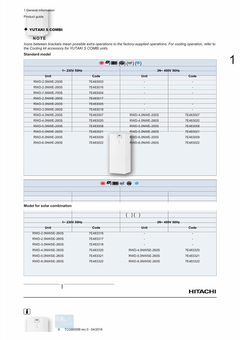
YUTAKI S COMBI
N O T E
Icons between brackets mean possible extra operations to the factory-supplied operations. For cooling operation, refer to
the Cooling kit accessory for YUTAKI S COMBI units.
Standard model
( ) ( ) ( )
1~ 230V 50Hz 3N~ 400V 50Hz
Unit Code Unit Code
RWD-2.0NWE-200S 7E483003 - -
RWD-2.0NWE-260S 7E483016 - -
RWD-2.5NWE-200S 7E483004 - -
RWD-2.5NWE-260S 7E483017 - -
RWD-3.0NWE-200S 7E483005 - -
RWD-3.0NWE-260S 7E483018 - -
RWD-4.0NWE-200S 7E483007 RWD-4.0NWE-200S 7E483007
RWD-4.0NWE-260S 7E483020 RWD-4.0NWE-260S 7E483020
RWD-5.0NWE-200S 7E483008 RWD-5.0NWE-200S 7E483008
RWD-5.0NWE-260S 7E483021 RWD-5.0NWE-260S 7E483021
RWD-6.0NWE-200S 7E483009 RWD-6.0NWE-200S 7E483009
RWD-6.0NWE-260S 7E483022 RWD-6.0NWE-260S 7E483022
Model for solar combination
( ) ( )
1~ 230V 50Hz 3N~ 400V 50Hz
Unit Code Unit Code
RWD-2.0NWSE-260S 7E483316 - -
RWD-2.5NWSE-260S 7E483317 - -
RWD-3.0NWSE-260S 7E483318 - -
RWD-4.0NWSE-260S 7E483320 RWD-4.0NWSE-260S 7E483320
RWD-5.0NWSE-260S 7E483321 RWD-5.0NWSE-260S 7E483321
RWD-6.0NWSE-260S 7E483322 RWD-6.0NWSE-260S 7E483322
8/16/2019 Hitachi Yutaki Series 2016 Αντλίες θερμότητας
http://slidepdf.com/reader/full/hitachi-yutaki-series-2016- 20/256
1 General information
Product guide
TCGB0098 rev.0 - 04/201610
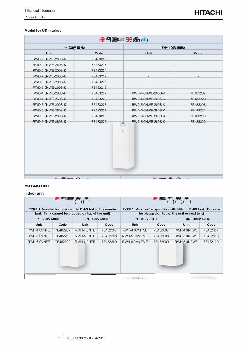
Model for UK market
( ) ( )
1~ 230V 50Hz 3N~ 400V 50Hz
Unit Code Unit Code
RWD-2.0NWE-200S-K 7E483203 - -
RWD-2.0NWE-260S-K 7E483216 - -
RWD-2.5NWE-200S-K 7E483204 - -
RWD-2.5NWE-260S-K 7E483217 - -
RWD-3.0NWE-200S-K 7E483205 - -
RWD-3.0NWE-260S-K 7E483218 - -
RWD-4.0NWE-200S-K 7E483207 RWD-4.0NWE-200S-K 7E483207
RWD-4.0NWE-260S-K 7E483220 RWD-4.0NWE-260S-K 7E483220
RWD-5.0NWE-200S-K 7E483208 RWD-5.0NWE-200S-K 7E483208
RWD-5.0NWE-260S-K 7E483221 RWD-5.0NWE-260S-K 7E483221
RWD-6.0NWE-200S-K 7E483209 RWD-6.0NWE-200S-K 7E483209
RWD-6.0NWE-260S-K 7E483222 RWD-6.0NWE-260S-K 7E483222
YUTAKI S80
Indoor unit
( ) ( ) ( ) ( ) ( )
TYPE 1: Version for operation in DHW but with a remote
tank (Tank cannot be plugged on top of the unit)
TYPE 2: Version for operation with Hitachi DHW tank (Tank can
be plugged on top of the unit or next to it)
1~ 230V 50Hz 3N~ 400V 50Hz 1~ 230V 50Hz 3N~ 400V 50Hz
Unit Code Unit Code Unit Code Unit Code
RWH-4.0VNFE 7E482207 RWH-4.0NFE 7E482307 RWH-4.0VNFWE 7E482007 RWH-4.0NFWE 7E482107
RWH-5.0VNFE 7E482208 RWH-5.0NFE 7E482308 RWH-5.0VNFWE 7E482008 RWH-5.0NFWE 7E482108
RWH-6.0VNFE 7E482209 RWH-6.0NFE 7E482309 RWH-6.0VNFWE 7E482009 RWH-6.0NFWE 7E482109
8/16/2019 Hitachi Yutaki Series 2016 Αντλίες θερμότητας
http://slidepdf.com/reader/full/hitachi-yutaki-series-2016- 21/256
1 General information
Product guide
TCGB0098 rev.0 - 04/201611
1
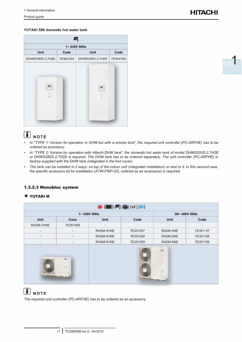
YUTAKI S80 domestic hot water tank
1~ 230V 50Hz
Unit Code Unit Code
DHWS200S-2.7H2E 7E544104 DHWS260S-2.7H2E 7E544105
N O T E
• In “TYPE 1: Version for operation in DHW but with a remote tank”, the required unit controller (PC-ARFHE) has to be
ordered as accessory.
• In “TYPE 2: Version for operation with Hitachi DHW tank”, the domestic hot water tank of model DHWS200S-2.7H2E
or DHWS260S-2.7H2E is required. The DHW tank has to be ordered separately. The unit controller (PC-ARFHE) is
factory-supplied with the DHW tank (integrated in the font cover).
• The tank can be installed in 2 ways: on top of the indoor unit (integrated installation) or next to it. In this second case,
the specic accessory kit for installation (ATW-FWP-02), ordered as an accessory) is required.
1.3.2.3 Monobloc system
YUTAKI M
( ) ( ) ( ) ( ) ( )
1~ 230V 50Hz 3N~ 400V 50Hz
Unit Code Unit Code Unit Code
RASM-3VNE 7E351005 - - - -
- - RASM-4VNE 7E351007 RASM-4NE 7E351107
- - RASM-5VNE 7E351008 RASM-5NE 7E351108
- - RASM-6VNE 7E351009 RASM-6NE 7E351109
N O T E
The required unit controller (PC-ARFHE) has to be ordered as an accessory.
8/16/2019 Hitachi Yutaki Series 2016 Αντλίες θερμότητας
http://slidepdf.com/reader/full/hitachi-yutaki-series-2016- 22/256
1 General information
Product guide
TCGB0098 rev.0 - 04/201612
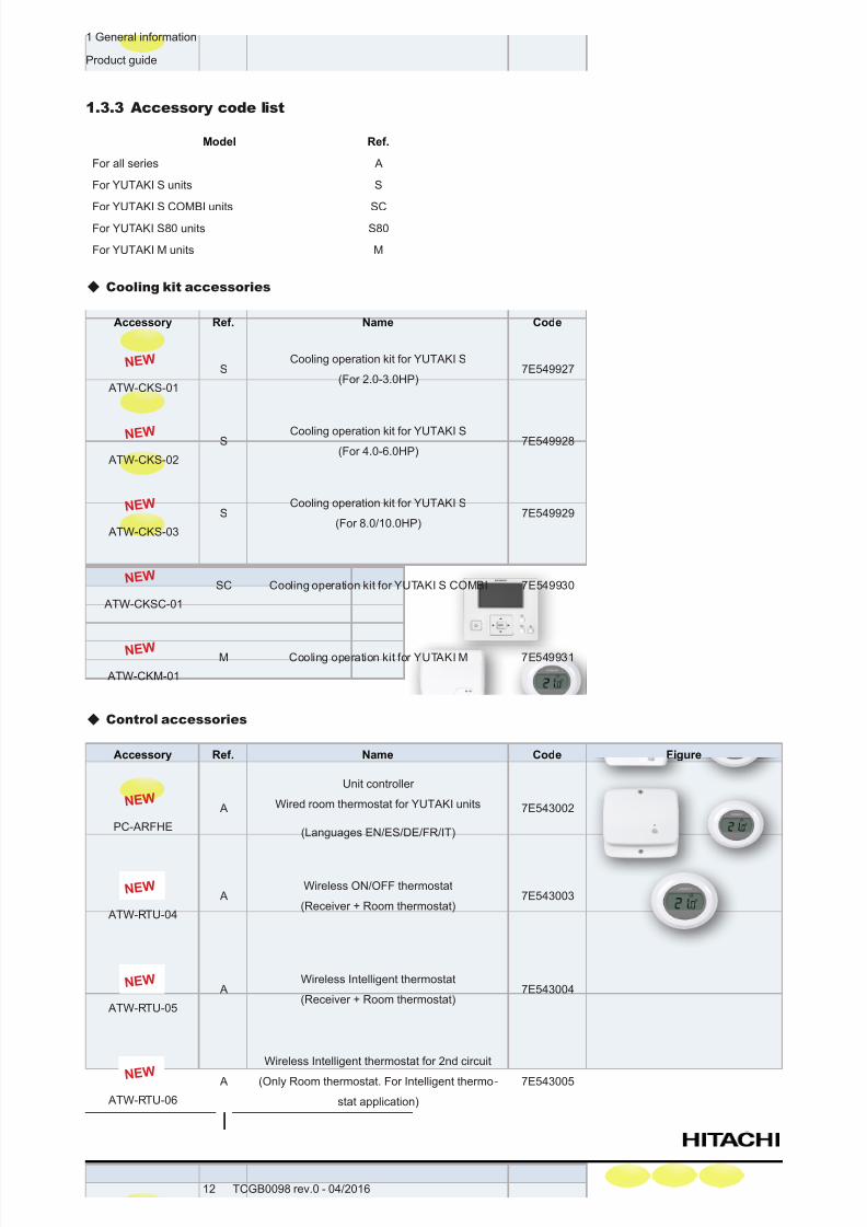
1.3.3 Accessory code list
Model Ref.
For all series A
For YUTAKI S units S
For YUTAKI S COMBI units SC
For YUTAKI S80 units S80
For YUTAKI M units M
Cooling kit accessories
Accessory Ref. Name Code
N E W
ATW-CKS-01
SCooling operation kit for YUTAKI S
(For 2.0-3.0HP)7E549927
N E W
ATW-CKS-02
SCooling operation kit for YUTAKI S
(For 4.0-6.0HP)7E549928
N E W
ATW-CKS-03
SCooling operation kit for YUTAKI S
(For 8.0/10.0HP)7E549929
N E W
ATW-CKSC-01
SC Cooling operation kit for YUTAKI S COMBI 7E549930
N E W
ATW-CKM-01
M Cooling operation kit for YUTAKI M 7E549931
Control accessories
Accessory Ref. Name Code Figure
N E W
PC-ARFHE
A
Unit controller
Wired room thermostat for YUTAKI units
(Languages EN/ES/DE/FR/IT)
7E543002
N E W
ATW-RTU-04
AWireless ON/OFF thermostat
(Receiver + Room thermostat)7E543003
N E W
ATW-RTU-05
AWireless Intelligent thermostat
(Receiver + Room thermostat)7E543004
N E W
ATW-RTU-06
A
Wireless Intelligent thermostat for 2nd circuit
(Only Room thermostat. For Intelligent thermo-
stat application)
7E543005
8/16/2019 Hitachi Yutaki Series 2016 Αντλίες θερμότητας
http://slidepdf.com/reader/full/hitachi-yutaki-series-2016- 23/256
1 General information
Product guide
TCGB0098 rev.0 - 04/201613
1
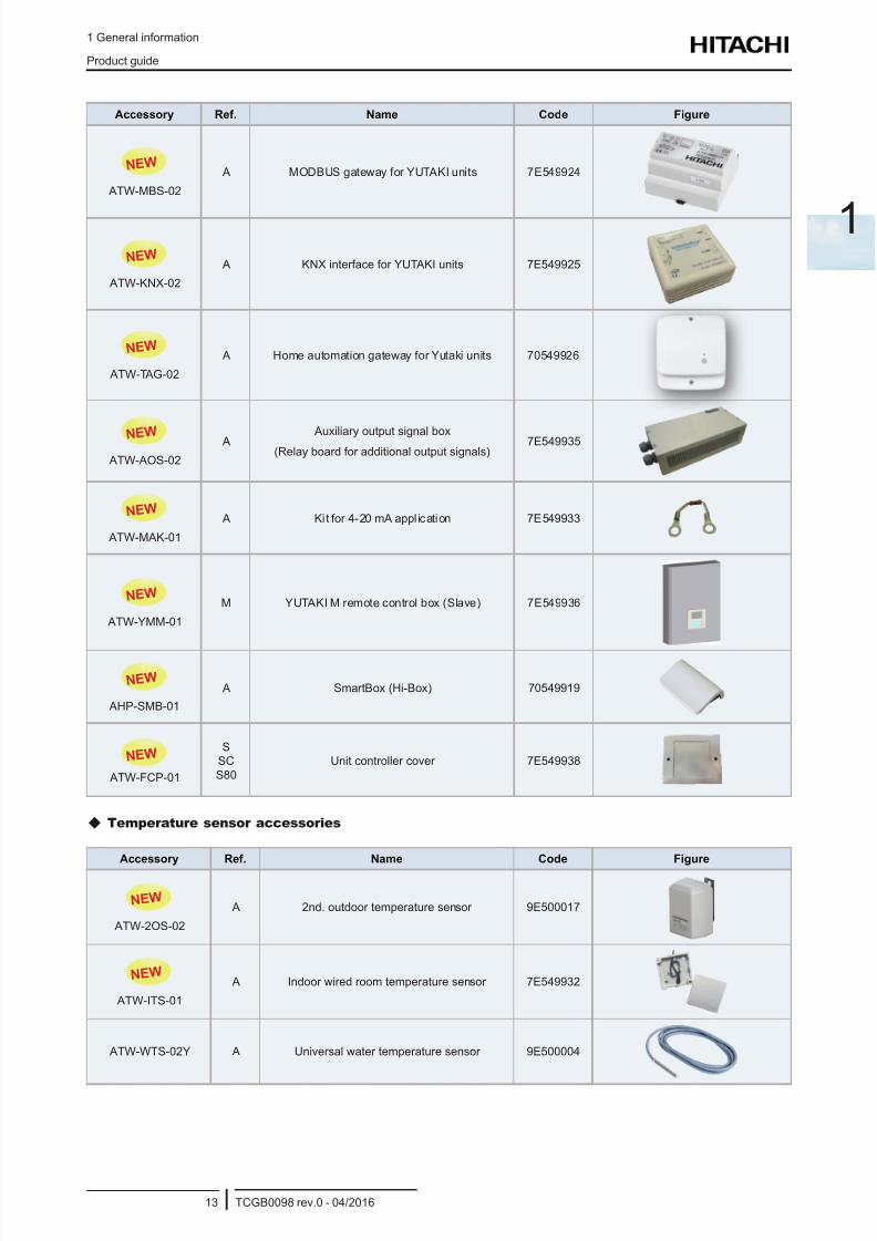
Accessory Ref. Name Code Figure
N E W
ATW-MBS-02
A MODBUS gateway for YUTAKI units 7E549924
N E W
ATW-KNX-02
A KNX interface for YUTAKI units 7E549925
N E W
ATW-TAG-02
A Home automation gateway for Yutaki units 70549926
N E W
ATW-AOS-02
A Auxiliary output signal box (Relay board for additional output signals)
7E549935
N E W
ATW-MAK-01
A Kit for 4-20 mA appl ication 7E549933
N E W
ATW-YMM-01
M YUTAKI M remote control box (Slave) 7E549936
N E W
AHP-SMB-01
A SmartBox (Hi-Box) 70549919
N E W
ATW-FCP-01
S
SC
S80
Unit controller cover 7E549938
Temperature sensor accessories
Accessory Ref. Name Code Figure
N E W
ATW-2OS-02
A 2nd. outdoor temperature sensor 9E500017
N E W
ATW-ITS-01
A Indoor wired room temperature sensor 7E549932
ATW-WTS-02Y A Universal water temperature sensor 9E500004
8/16/2019 Hitachi Yutaki Series 2016 Αντλίες θερμότητας
http://slidepdf.com/reader/full/hitachi-yutaki-series-2016- 24/256
1 General information
Product guide
TCGB0098 rev.0 - 04/201614
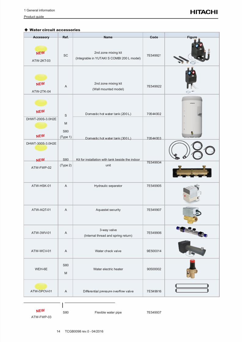
Water circuit accessories
Accessory Ref. Name Code Figure
N E W
ATW-2KT-03
SC2nd zone mixing kit
(Integrable in YUTAKI S COMBI 200 L model)
7E549921
N E W
ATW-2TK-04
A2nd zone mixing kit
(Wall mounted model)7E549922
N E W
DHWT-200S-3.0H2E
S
M
S80
(Type 1)
Domestic hot water tank (200 L) 70544002
N E W
DHWT-300S-3.0H2E
Domestic hot water tank (300 L) 70544003
N E W
ATW-FWP-02
S80
(Type 2)
Kit for installation with tank beside the indoor
unit7E549934
ATW-HSK-01 A Hydraulic separator 7E549905
ATW-AQT-01 A Aquastat security 7E549907
ATW-3WV-01 A3-way valve
(Internal thread and spring return)7E549906
ATW-WCV-01 A Water check valve 9E500014
WEH-6E
S80
M
Water electric heater 90500002
ATW-DPOV-01 A Differential pressure overow valve 7E549916
N E W
ATW-FWP-03
S80 Flexible water pipe 7E549937
8/16/2019 Hitachi Yutaki Series 2016 Αντλίες θερμότητας
http://slidepdf.com/reader/full/hitachi-yutaki-series-2016- 25/256
2 Features and benets
TCGB0098 rev.0 - 04/201615
2
Index
2.1 Selection benets ..................................................................................................................................16
2.1.1 Wide selection range ..................................................................................................................................... 16
2.1.2 High efciency system. Wide capacity range ................................................................................................ 19
2.1.3 Wide range of accessories and components ................................................................................................19
2.2 Installation benets................................................................................................................................26
2.2.1 YUTAKI S reduced dimensions ..................................................................................................................... 26
2.2.2 YUTAKI S80 improved connections ..............................................................................................................27
2.3 Maintenance benets ............................................................................................................................28
2.3.1 Filter + for the water circuit ............................................................................................................................ 28
2.3.2 New manual air purger for YUTAKI S COMBI ............................................................................................... 28
2.4 Control features ..................................................................................................................................... 29
2.4.1 Unit controller: more functions ....................................................................................................................... 29
2.4.2 I/O and sensor functions ............................................................................................................................... 29
2 . F e a t u r e s a n d b e n e f i t s
8/16/2019 Hitachi Yutaki Series 2016 Αντλίες θερμότητας
http://slidepdf.com/reader/full/hitachi-yutaki-series-2016- 26/256
2 Features and benets
Selection benets
TCGB0098 rev.0 - 04/201616
2.1 Selection benets
2.1.1 Wide selection range
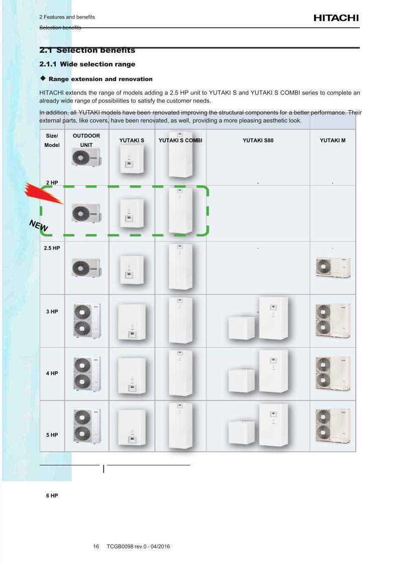
Range extension and renovation
HITACHI extends the range of models adding a 2.5 HP unit to YUTAKI S and YUTAKI S COMBI series to complete an
already wide range of possibilities to satisfy the customer needs.
In addition, all YUTAKI models have been renovated improving the structural components for a better performance. Their
external parts, like covers, have been renovated, as well, providing a more pleasing aesthetic look.
Size/
Model
OUTDOOR
UNIT YUTAKI S YUTAKI S COMBI YUTAKI S80 YUTAKI M
2 HP - -
2.5 HP - -
3 HP -
4 HP
5 HP
6 HP
N E W
8/16/2019 Hitachi Yutaki Series 2016 Αντλίες θερμότητας
http://slidepdf.com/reader/full/hitachi-yutaki-series-2016- 27/256
2 Features and benets
Selection benets
TCGB0098 rev.0 - 04/201617
2
Size/
Model
OUTDOOR
UNIT YUTAKI S YUTAKI S COMBI YUTAKI S80 YUTAKI M
8 HP - - -
10 HP - - -
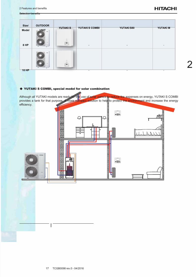
YUTAKI S COMBI, special model for solar combination
Although all YUTAKI models are ready for the use of solar panels to reduce the expenses on energy, YUTAKI S COMBIprovides a tank for that purpose. A more compact solution to help to protect the environment and increase the energy
efciency.
8/16/2019 Hitachi Yutaki Series 2016 Αντλίες θερμότητας
http://slidepdf.com/reader/full/hitachi-yutaki-series-2016- 28/256
2 Features and benets
Selection benets
TCGB0098 rev.0 - 04/201618
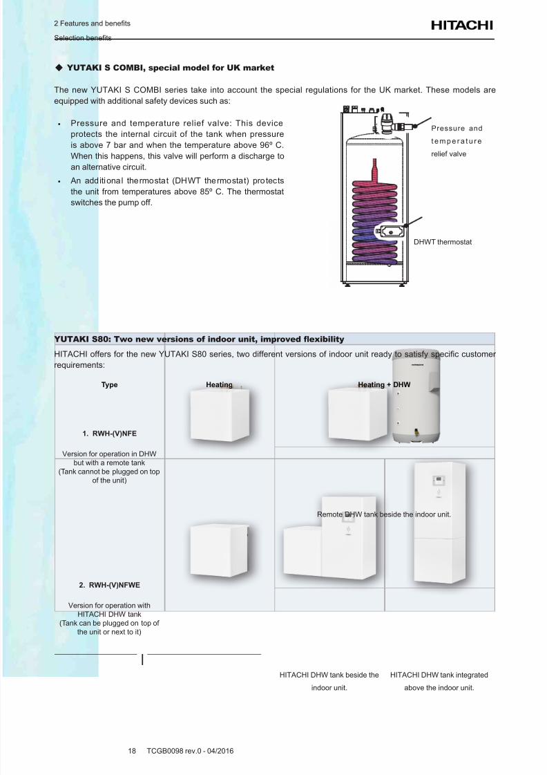
YUTAKI S COMBI, special model for UK market
The new YUTAKI S COMBI series take into account the special regulations for the UK market. These models are
equipped with additional safety devices such as:
• Pressure and temperature relief valve: This device
protects the internal circuit of the tank when pressureis above 7 bar and when the temperature above 96º C.
When this happens, this valve will perform a discharge to
an alternative circuit.
• An additional thermostat (DHWT thermostat) protects
the unit from temperatures above 85º C. The thermostat
switches the pump off.
Pressure and
t e m p e r a t u r e
relief valve
DHWT thermostat
YUTAKI S80: Two new versions of indoor unit, improved exibility
HITACHI offers for the new YUTAKI S80 series, two different versions of indoor unit ready to satisfy specic customer
requirements:
Type Heating Heating + DHW
1. RWH-(V)NFE
Version for operation in DHW
but with a remote tank
(Tank cannot be plugged on top
of the unit)
Remote DHW tank beside the indoor unit.
2. RWH-(V)NFWE
Version for operation with
HITACHI DHW tank
(Tank can be plugged on top of
the unit or next to it)
HITACHI DHW tank beside the
indoor unit.
HITACHI DHW tank integrated
above the indoor unit.
8/16/2019 Hitachi Yutaki Series 2016 Αντλίες θερμότητας
http://slidepdf.com/reader/full/hitachi-yutaki-series-2016- 29/256
2 Features and benets
Selection benets
TCGB0098 rev.0 - 04/201619
2
2.1.2 High efciency system. Wide capacity range
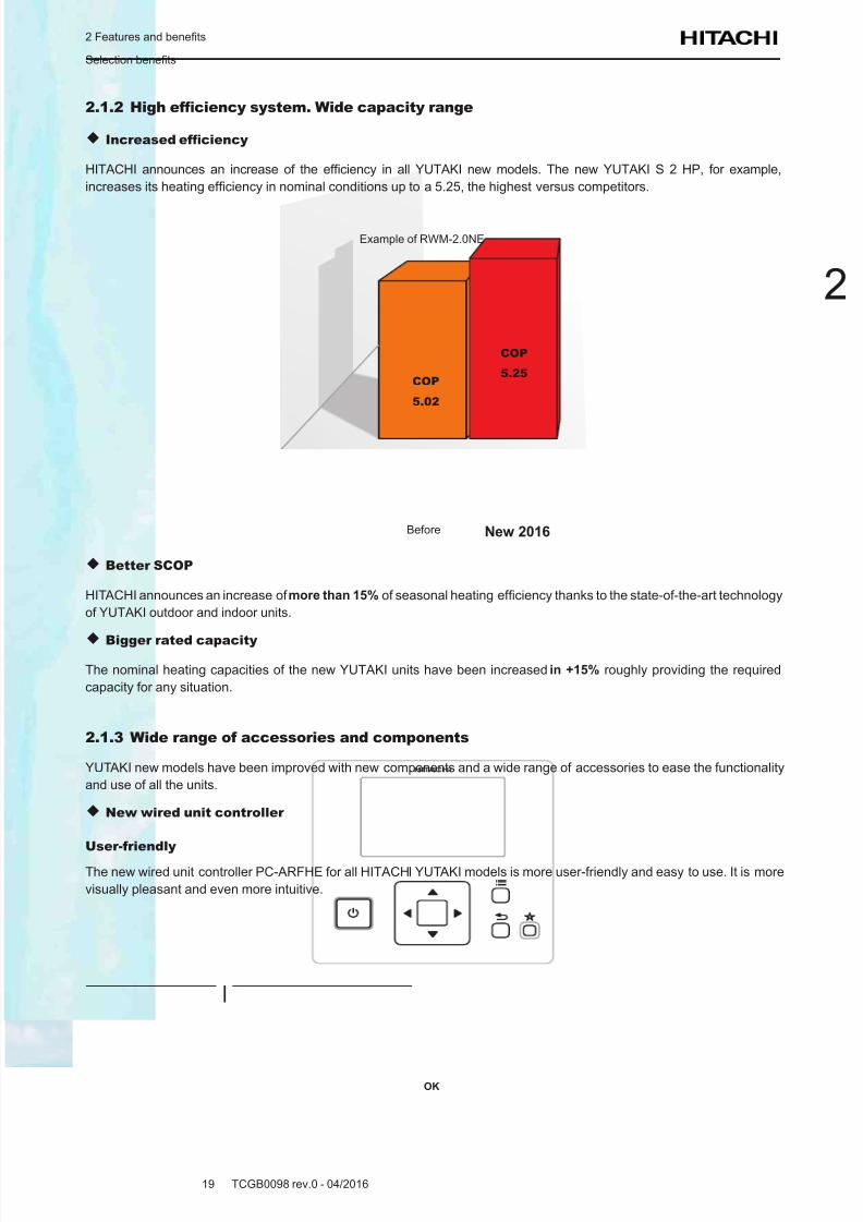
Increased efciency
HITACHI announces an increase of the efciency in all YUTAKI new models. The new YUTAKI S 2 HP, for example,
increases its heating efciency in nominal conditions up to a 5.25, the highest versus competitors.
Before New 2016
COP
5.25COP
5.02
Example of RWM-2.0NE
Better SCOP
HITACHI announces an increase of more than 15% of seasonal heating efciency thanks to the state-of-the-art technology
of YUTAKI outdoor and indoor units.
Bigger rated capacity
The nominal heating capacities of the new YUTAKI units have been increased in +15% roughly providing the required
capacity for any situation.
2.1.3 Wide range of accessories and components
YUTAKI new models have been improved with new components and a wide range of accessories to ease the functionality
and use of all the units.
New wired unit controller
User-friendly
The new wired unit controller PC-ARFHE for all HITACHI YUTAKI models is more user-friendly and easy to use. It is more
visually pleasant and even more intuitive.
OK
8/16/2019 Hitachi Yutaki Series 2016 Αντλίες θερμότητας
http://slidepdf.com/reader/full/hitachi-yutaki-series-2016- 30/256
2 Features and benets
Selection benets
TCGB0098 rev.0 - 04/201620
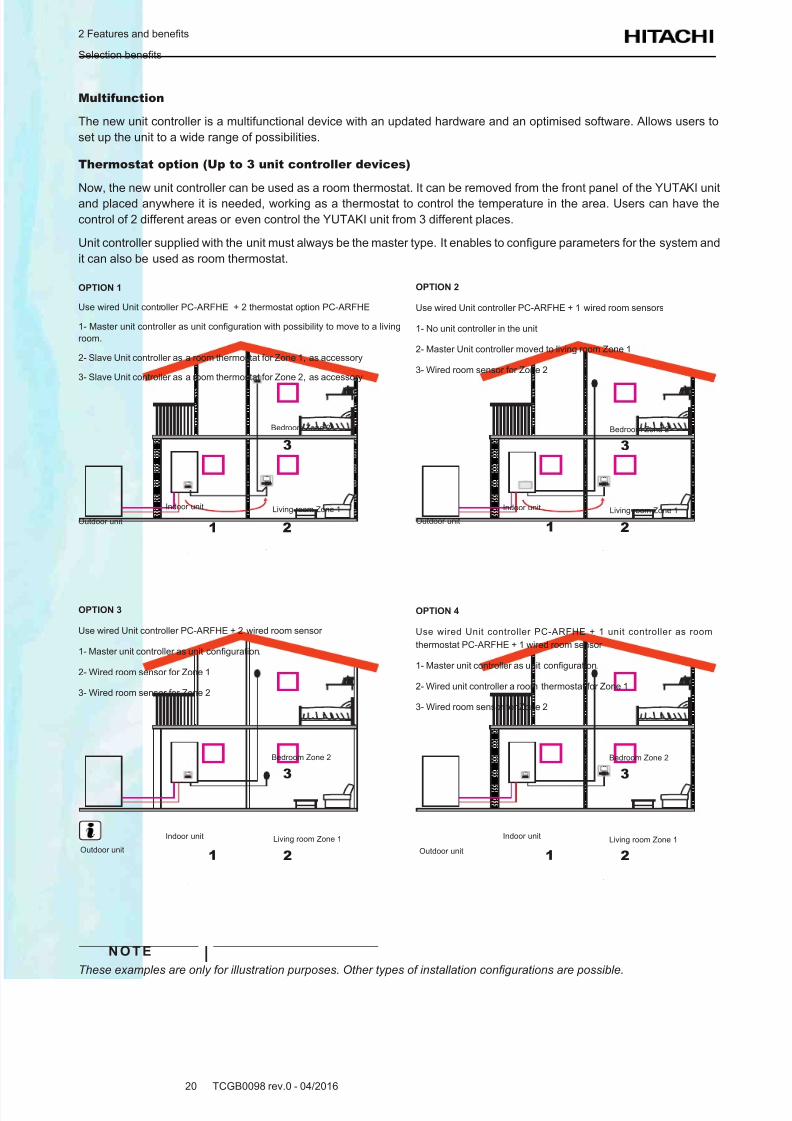
Multifunction
The new unit controller is a multifunctional device with an updated hardware and an optimised software. Allows users to
set up the unit to a wide range of possibilities.
Thermostat option (Up to 3 unit controller devices)
Now, the new unit controller can be used as a room thermostat. It can be removed from the front panel of the YUTAKI unit
and placed anywhere it is needed, working as a thermostat to control the temperature in the area. Users can have the
control of 2 different areas or even control the YUTAKI unit from 3 different places.
Unit controller supplied with the unit must always be the master type. It enables to congure parameters for the system and
it can also be used as room thermostat.
OK
OK
OK
OK
OK OK
OK
OPTION 1
Use wired Unit controller PC-ARFHE + 2 thermostat option PC-ARFHE
1- Master unit controller as unit conguration with possibility to move to a living
room.
2- Slave Unit controller as a room thermostat for Zone 1, as accessory
3- Slave Unit controller as a room thermostat for Zone 2, as accessory
Outdoor unit
Indoor unit
1 2
3
Living room Zone 1
Bedroom Zone 2
Outdoor unit
Indoor unit
1 2
3
Living room Zone 1
Bedroom Zone 2
Outdoor unit
Indoor unit
1 2
3
Living room Zone 1
Bedroom Zone 2
Outdoor unit
Indoor unit
1 2
3
Living room Zone 1
Bedroom Zone 2
OPTION 2
Use wired Unit controller PC-ARFHE + 1 wired room sensors
1- No unit controller in the unit
2- Master Unit controller moved to living room Zone 1
3- Wired room sensor for Zone 2
OPTION 3
Use wired Unit controller PC-ARFHE + 2 wired room sensor
1- Master unit controller as unit conguration.
2- Wired room sensor for Zone 1
3- Wired room sensor for Zone 2
OPTION 4
Use wired Unit controller PC-ARFHE + 1 unit controller as room
thermostat PC-ARFHE + 1 wired room sensor
1- Master unit controller as unit conguration.
2- Wired unit controller a room thermostat for Zone 1
3- Wired room sensor for Zone 2
N O T E
These examples are only for illustration purposes. Other types of installation congurations are possible.
8/16/2019 Hitachi Yutaki Series 2016 Αντλίες θερμότητας
http://slidepdf.com/reader/full/hitachi-yutaki-series-2016- 31/256
2 Features and benets
Selection benets
TCGB0098 rev.0 - 04/201621
2
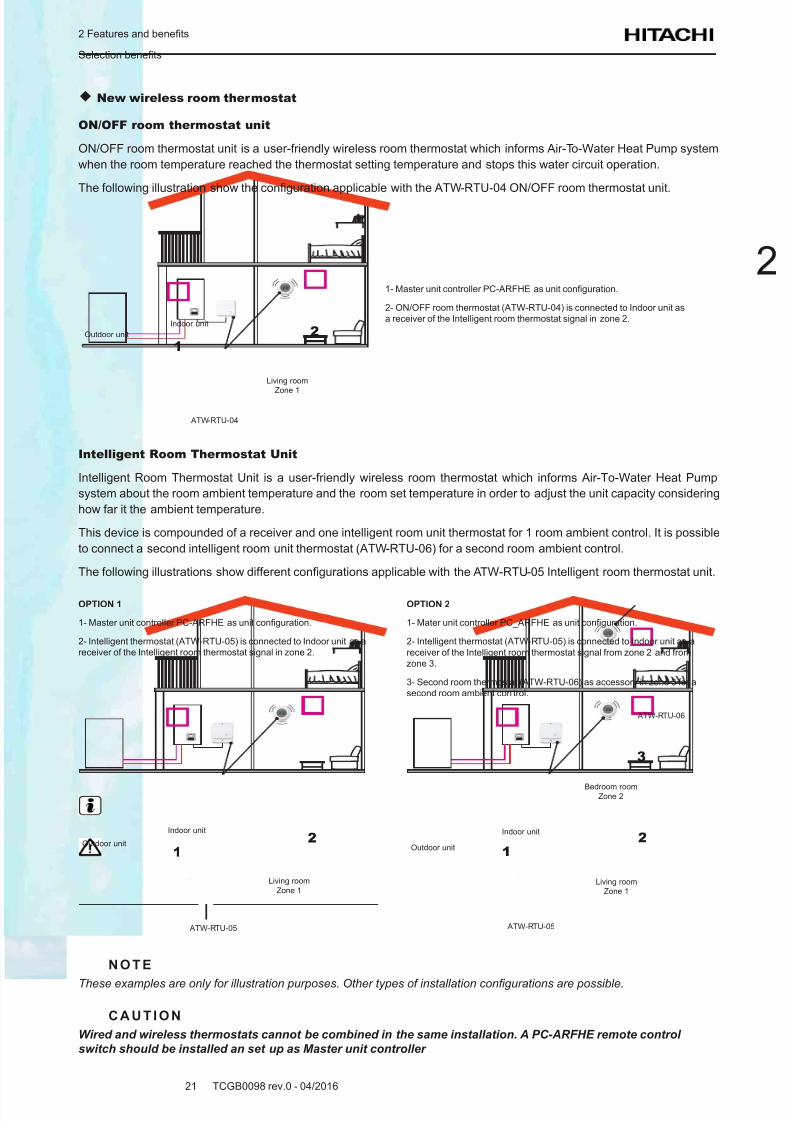
New wireless room thermostat
ON/OFF room thermostat unit
ON/OFF room thermostat unit is a user-friendly wireless room thermostat which informs Air-To-Water Heat Pump system
when the room temperature reached the thermostat setting temperature and stops this water circuit operation.
The following illustration show the conguration applicable with the ATW-RTU-04 ON/OFF room thermostat unit.
OK
Outdoor unit
Indoor unit
1
2
Living room
Zone 1
ATW-RTU-04
1- Master unit controller PC-ARFHE as unit conguration.
2- ON/OFF room thermostat (ATW-RTU-04) is connected to Indoor unit as
a receiver of the Intelligent room thermostat signal in zone 2.
Intelligent Room Thermostat Unit
Intelligent Room Thermostat Unit is a user-friendly wireless room thermostat which informs Air-To-Water Heat Pump
system about the room ambient temperature and the room set temperature in order to adjust the unit capacity considering
how far it the ambient temperature.
This device is compounded of a receiver and one intelligent room unit thermostat for 1 room ambient control. It is possible
to connect a second intelligent room unit thermostat (ATW-RTU-06) for a second room ambient control.
The following illustrations show different congurations applicable with the ATW-RTU-05 Intelligent room thermostat unit.
OPTION 1
1- Master unit controller PC-ARFHE as unit conguration.
2- Intelligent thermostat (ATW-RTU-05) is connected to Indoor unit as a
receiver of the Intelligent room thermostat signal in zone 2.
OK
Outdoor unit
Indoor unit
1
2
Living room
Zone 1
ATW-RTU-05
OPTION 2
1- Mater unit controller PC_ARFHE as unit conguration.
2- Intelligent thermostat (ATW-RTU-05) is connected to Indoor unit as a
receiver of the Intelligent room thermostat signal from zone 2 and from
zone 3.
3- Second room thermostat (ATW-RTU-06) as accessory in zone 3 for a
second room ambient control.
OK
1
2
3
Living room
Zone 1
Bedroom roomZone 2
Outdoor unit
Indoor unit
ATW-RTU-05
ATW-RTU-06
N O T E
These examples are only for illustration purposes. Other types of installation congurations are possible.
C A U T I O N
Wired and wireless thermostats cannot be combined in the same installation. A PC-ARFHE remote control
switch should be installed an set up as Master unit controller
8/16/2019 Hitachi Yutaki Series 2016 Αντλίες θερμότητας
http://slidepdf.com/reader/full/hitachi-yutaki-series-2016- 32/256
2 Features and benets
Selection benets
TCGB0098 rev.0 - 04/201622
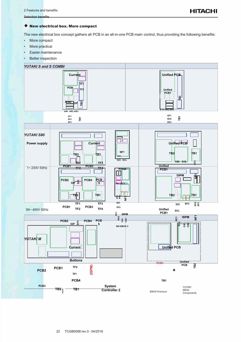
New electrical box. More compact
The new electrical box concept gathers all PCB in an all-in-one PCB main control, thus providing the following benets:
• More compact
• More practical
• Easier maintenance
• Better inspection
YUTAKI S and S COMBI
Current Unifed PCB
PCB1
PCB2
TF1
TF2
52P T B 2
AR1 AR2 AR3
T B 1
EF1
EF2EF3
Unified
PCB1
AR2 AR3
T B 2
T
B 1
EF1
EF2
EF3
ETH
YUTAKI S80
Power supply Current Unifed PCB
1~ 230V 50Hz
PF1
NF1
PV104
52C DCL
INV.EBOX 1~
PCB1
PCB2
TF1
TF2
52P
TB2 TB1
E F 3
PCB3
TF3
TF4
PCB4 PCB5
Unified
PCB1
TB2 TB1
DIPM
52C DCL
E F 3
N F 1
3N~ 400V 50HzPCB1
PCB2
TF1
TF2
52P
TB2 TB1
E F 3
PCB3
TF3
TF4
PCB4 PCB
5INV.EBOX 3~
P F 1
N F 1
ISPM
52C
DCL
P F 2
R C 1
R C 2
C A 1
C A 2
Unified
PCB1
TB2 TB1
ISPM
52C
DCL
P F 1
EF3
N F 1
P F 2
C A 2
C A 1
R C 1
R C 2
YUTAKI M
Current Unifed PCB
PCB1PCB2
TF1
TF2
Bottons
PCB3
TB2 TB1
PCB4
( I S P M )
System
Controller 2
PCB1
TB1
Unified
PCB
T B 2
+
EBOX Premium
YUTAKI
EBOX
Components
8/16/2019 Hitachi Yutaki Series 2016 Αντλίες θερμότητας
http://slidepdf.com/reader/full/hitachi-yutaki-series-2016- 33/256
2 Features and benets
Selection benets
TCGB0098 rev.0 - 04/201623
2
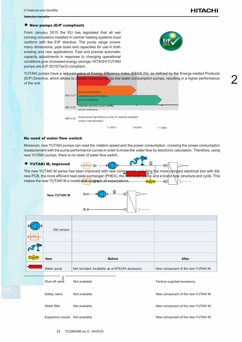
New pumps (ErP compliant)
From January 2015 the EU has legislated that all wet
running circulators installed in central heating systems must
conform with the ErP directive. The pump range covers
many dimensions, pipe sizes and capacities for use in both
existing and new applications. Fast and precise automatic
capacity adjustments in response to changing operational
conditions give increased energy savings. HITACHI YUTAKI
pumps are ErP 2015(Tier2) compliant.
YUTAKI pumps have a reduced value of Energy Efciency Index (EEI≤0.23), as dened by the Energy-related Products
(ErP) Directive, which allows to classify these pumps as low water consumption pumps, resulting in a higher performance
of the unit.
EEI> 0.27
EEI> 0.23
EEI≤ 0.23
1.1.2013 1.8.2015 1.1.2020
Stand-alone glandless
circulation pumps for heating
and air-conditioning
Integrated glandless pumps Heating
and air-conditioning
Energy-saving high-efciency pumps for replacing integrated
pumps in heat generators
No need of water ow switch
Moreover, new YUTAKI pumps can read the rotation speed and the power consumption, crossing the power consumption
measurement with the pump performance curves in order to know the water ow by electronic calculation. Therefore, using
new YUTAKI pumps, there is no need of water ow switch.
YUTAKI M, improved
The new YUTAKI M series has been improved with new components including the more compact electrical box with the
new PCB, the more efcient heat plate exchanger (PHEX), the new water pump and a brand new structure and cycle. This
makes the new YUTAKI M a model that exceeds all expectations.
Old version
New YUTAKI M
Item Before After
Water pump Not included. Avai lable as a HITACHI accessory New component of the new YUTAKI M.
Shut-off valve Not available Factory-supplied accessory.
Safety valve Not available New component of the new YUTAKI M.
Water lter Not available New component of the new YUTAKI M.
Expansion vessel Not available New component of the new YUTAKI M.
8/16/2019 Hitachi Yutaki Series 2016 Αντλίες θερμότητας
http://slidepdf.com/reader/full/hitachi-yutaki-series-2016- 34/256
2 Features and benets
Selection benets
TCGB0098 rev.0 - 04/201624
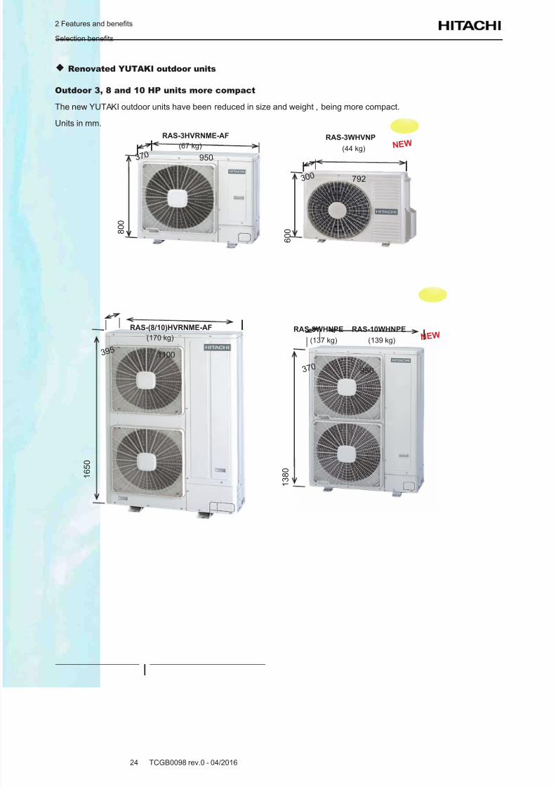
Renovated YUTAKI outdoor units
Outdoor 3, 8 and 10 HP units more compact
The new YUTAKI outdoor units have been reduced in size and weight , being more compact.
Units in mm.
RAS-3WHVNP(44 kg) N E W
RAS-3HVRNME-AF(67 kg)
3 7 0
3 0 0
950
792
8 0 0
6 0 0
RAS-8WHNPE RAS-10WHNPE
(137 kg) (139 kg) N E WRAS-(8/10)HVRNME-AF
(170 kg)
3 9 5
3 7 0
1100
950
1 6 5 0
1 3 8 0
8/16/2019 Hitachi Yutaki Series 2016 Αντλίες θερμότητας
http://slidepdf.com/reader/full/hitachi-yutaki-series-2016- 35/256
2 Features and benets
Selection benets
TCGB0098 rev.0 - 04/201625
2
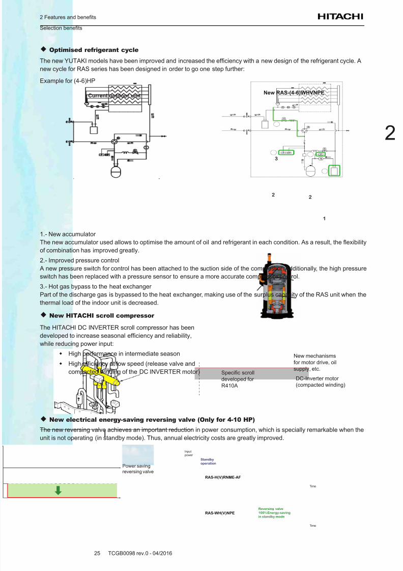
Optimised refrigerant cycle
The new YUTAKI models have been improved and increased the efciency with a new design of the refrigerant cycle. A
new cycle for RAS series has been designed in order to go one step further:
Example for (4-6)HP
1
2
3
2
Current outdoor unitNew RAS-(4-6)WHVNPE
1.- New accumulator
The new accumulator used allows to optimise the amount of oil and refrigerant in each condition. As a result, the exibility
of combination has improved greatly.
2.- Improved pressure control
A new pressure switch for control has been attached to the suction side of the compressor. Additionally, the high pressure
switch has been replaced with a pressure sensor to ensure a more accurate compressor control.
3.- Hot gas bypass to the heat exchanger
Part of the discharge gas is bypassed to the heat exchanger, making use of the surplus capacity of the RAS unit when the
thermal load of the indoor unit is decreased.
New HITACHI scroll compressor
The HITACHI DC INVERTER scroll compressor has been
developed to increase seasonal efciency and reliability,
while reducing power input:
High performance in intermediate season
High efciency at low speed (release valve and
compacted winding of the DC INVERTER motor)
New mechanisms
for motor drive, oil
supply, etc.
DC-Inverter motor
(compacted winding)
Specic scroll
developed for
R410A
New electrical energy-saving reversing valve (Only for 4-10 HP)
The new reversing valve achieves an important reduction in power consumption, which is specially remarkable when the
unit is not operating (in standby mode). Thus, annual electricity costs are greatly improved.
Power saving
reversing valve
Standby
operation
RAS-H(V)RNME-AF
Input
power
Time
Time
Reversing valve
100% Energy-saving
in standby modeRAS-WH(V)NPE
8/16/2019 Hitachi Yutaki Series 2016 Αντλίες θερμότητας
http://slidepdf.com/reader/full/hitachi-yutaki-series-2016- 36/256
2 Features and benets
Installation benets
TCGB0098 rev.0 - 04/201626
2.2 Installation benets
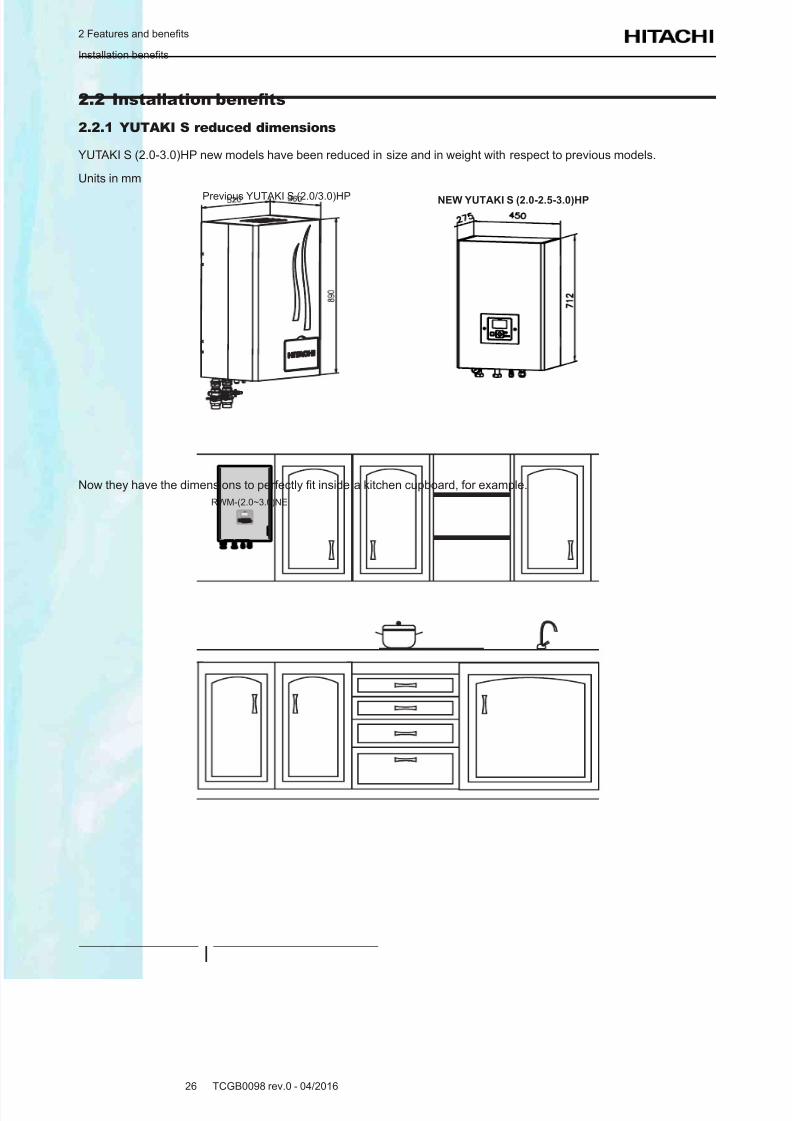
2.2.1 YUTAKI S reduced dimensions
YUTAKI S (2.0-3.0)HP new models have been reduced in size and in weight with respect to previous models.
Units in mm
Previous YUTAKI S (2.0/3.0)HP NEW YUTAKI S (2.0-2.5-3.0)HP
Now they have the dimensions to perfectly t inside a kitchen cupboard, for example.
RWM-(2.0~3.0)NE
8/16/2019 Hitachi Yutaki Series 2016 Αντλίες θερμότητας
http://slidepdf.com/reader/full/hitachi-yutaki-series-2016- 37/256
2 Features and benets
Installation benets
TCGB0098 rev.0 - 04/201627
2
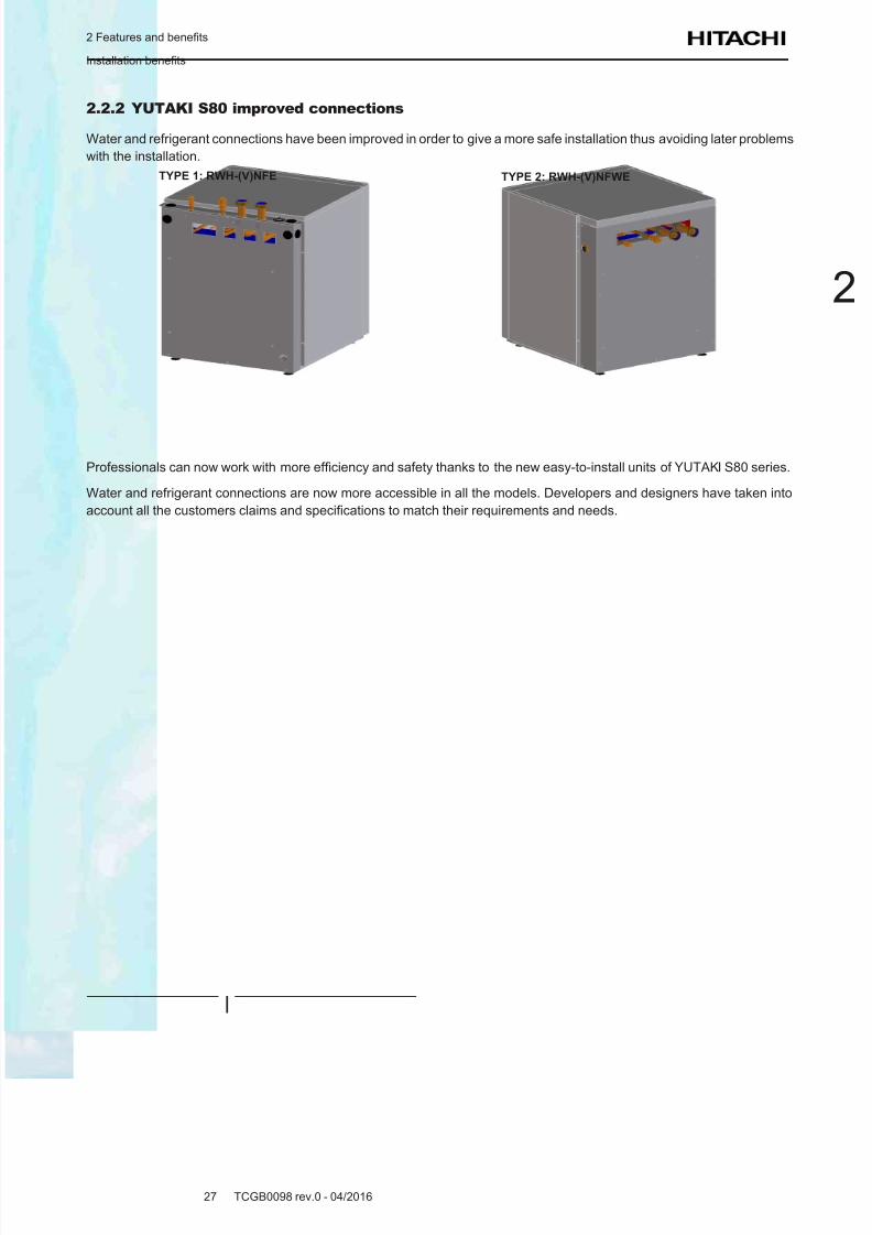
2.2.2 YUTAKI S80 improved connections
Water and refrigerant connections have been improved in order to give a more safe installation thus avoiding later problems
with the installation.
TYPE 1: RWH-(V)NFE TYPE 2: RWH-(V)NFWE
Professionals can now work with more efciency and safety thanks to the new easy-to-install units of YUTAKI S80 series.
Water and refrigerant connections are now more accessible in all the models. Developers and designers have taken into
account all the customers claims and specications to match their requirements and needs.
8/16/2019 Hitachi Yutaki Series 2016 Αντλίες θερμότητας
http://slidepdf.com/reader/full/hitachi-yutaki-series-2016- 38/256
2 Features and benets
Maintenance benets
TCGB0098 rev.0 - 04/201628
2.3 Maintenance benets
HITACHI YUTAKI series incorporates new components that make the maintenance an easier work to do. Aspects that
makes the new YUTAKI series the most condent in the market:
• High quality components
• Longer life cycle assets
• More reliability-centered designs
• etc.
2.3.1 Filter + for the water circuit
Filter + is an on-off ball valve containing an interchangeable cylindrical lter which is easy to inspect and remove for normal
maintenance operations. A single valve therefore has two important functions: perfect sealing of the ball valves and careful
ltering of the uid, so that their great reliability protects all the components of the new HITACHI YUTAKI units.
Compared with the traditional use of three components (one lter and two shut-off valves), apart from the obvious
advantages in terms of cost, installation and space, the Filter + means much smaller load losses.
OUTLET OUTLETINLET INLET
Ball in closed position Ball in cleaning position
Bal l ready to c lean-cut
with flush. An extra 22º is
needed to rotate the ball.
A t th is po si ti on , th e
mesh can be removed
from the filter ball for
maintenance tasks
2.3.2 New manual air purger for YUTAKI S COMBI
HITACHI includes a manual air purger for the new YUTAKI S COMBI models to improve maintenance operation.
Following the advice of technicians worldwide, for the maintenance operations in which the emptying of the water in the
circuit is necessary, the location of this manual air purger provides better operations for the purging of the air contained
inside the circuit.
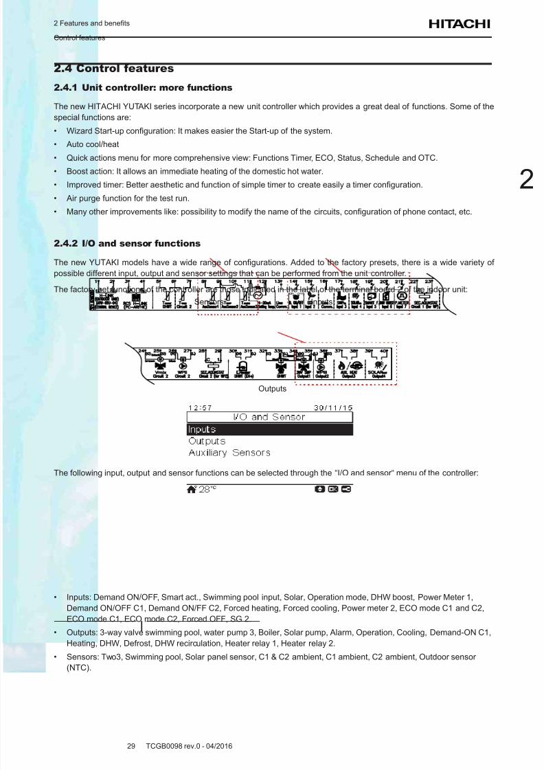
8/16/2019 Hitachi Yutaki Series 2016 Αντλίες θερμότητας
http://slidepdf.com/reader/full/hitachi-yutaki-series-2016- 39/256
2 Features and benets
Control features
TCGB0098 rev.0 - 04/201629
2
2.4 Control features
2.4.1 Unit controller: more functions
The new HITACHI YUTAKI series incorporate a new unit controller which provides a great deal of functions. Some of the
special functions are:
• Wizard Start-up conguration: It makes easier the Start-up of the system.• Auto cool/heat
• Quick actions menu for more comprehensive view: Functions Timer, ECO, Status, Schedule and OTC.
• Boost action: It allows an immediate heating of the domestic hot water.
• Improved timer: Better aesthetic and function of simple timer to create easily a timer conguration.
• Air purge function for the test run.
• Many other improvements like: possibility to modify the name of the circuits, conguration of phone contact, etc.
2.4.2 I/O and sensor functions
The new YUTAKI models have a wide range of congurations. Added to the factory presets, there is a wide variety of
possible different input, output and sensor settings that can be performed from the unit controller.
The factory-set functions of the controller are those indicated in the label of the terminal board 2 of the indoor unit:
InputsSensors
Outputs
The following input, output and sensor functions can be selected through the “I/O and sensor“ menu of the controller:
• Inputs: Demand ON/OFF, Smart act., Swimming pool input, Solar, Operation mode, DHW boost, Power Meter 1,
Demand ON/OFF C1, Demand ON/FF C2, Forced heating, Forced cooling, Power meter 2, ECO mode C1 and C2,
ECO mode C1, ECO mode C2, Forced OFF, SG 2.
• Outputs: 3-way valve swimming pool, water pump 3, Boiler, Solar pump, Alarm, Operation, Cooling, Demand-ON C1,
Heating, DHW, Defrost, DHW recirculation, Heater relay 1, Heater relay 2.
• Sensors: Two3, Swimming pool, Solar panel sensor, C1 & C2 ambient, C1 ambient, C2 ambient, Outdoor sensor
(NTC).

8/16/2019 Hitachi Yutaki Series 2016 Αντλίες θερμότητας
http://slidepdf.com/reader/full/hitachi-yutaki-series-2016- 40/256
8/16/2019 Hitachi Yutaki Series 2016 Αντλίες θερμότητας
http://slidepdf.com/reader/full/hitachi-yutaki-series-2016- 41/256
3 General data
TCGB0098 rev.0 - 04/201631
3
Index
3.1 Capacity tables ...................................................................................................................................... 32
3.1.1 Nominal capacity-performance tables ........................................................................................................... 32
3.1.1.1 Considerations .............................................................................................................................. 32
3.1.1.2 Capacity-performance data .......................................................................................................... 32
3.2 ERP performance data .......................................................................................................................... 35
3.2.1 General considerations ................................................................................................................................. 35
3.2.2 General ERP data for space heaters ............................................................................................................ 35
3.2.2.1 ERP data - YUTAKI S ................................................................................................................... 35
3.2.2.2 ERP data - YUTAKI S COMBI ......................................................................................................41
3.2.2.3 ERP data - YUTAKI S80 ............................................................................................................... 46
3.2.2.4 ERP data - YUTAKI M ................................................................................................................... 49
3.2.2.5 ERP additional data - YUTAKI S ...................................................................................................52
3.2.2.6 ERP additional data - YUTAKI S COMBI ...................................................................................... 53
3.2.2.7 ERP additional data - YUTAKI S80 ...............................................................................................54
3.2.3 General ERP data for combi heaters (YUTAKI S COMBI & S80) ................................................................. 55
3.2.3.1 YUTAKI S COMBI .........................................................................................................................55
3.2.3.2 YUTAKI S80 .................................................................................................................................. 56
3.2.4 General ERP data for hot water storage tanks (YUTAKI S , YUTAKI M & YUTAKI S 80 RWH-4.0VNFE ..... 56
3.3 General specications ...........................................................................................................................57
3.3.1 Considerations .............................................................................................................................................. 57
3.3.2 Split system - Outdoor unit ............................................................................................................................ 58
3.3.3 Split system - Indoor unit ............................................................................................................................... 60
3.3.3.1 YUTAKI S ...................................................................................................................................... 60
3.3.3.2 YUTAKI S COMBI .........................................................................................................................63
3.3.3.3 YUTAKI S80 .................................................................................................................................. 69
3.3.4 Monobloc system - YUTAKI M....................................................................................................................... 72
3.3.5 Domestic Hot Water Tank .............................................................................................................................. 74
3.4 Component data .................................................................................................................................... 75
3.4.1 Split system - Outdoor unit ............................................................................................................................ 753.4.2 Split system - Indoor unit ............................................................................................................................... 77
3.4.2.1 YUTAKI S ...................................................................................................................................... 77
3.4.2.2 YUTAKI S COMBI .........................................................................................................................78
3.4.2.3 YUTAKI S80 .................................................................................................................................. 82
3.4.3 Monobloc system - YUTAKI M....................................................................................................................... 83
3.5 Electrical data ........................................................................................................................................ 85
3.5.1 Considerations .............................................................................................................................................. 85
3.5.2 Split system - Outdoor unit ............................................................................................................................ 86
3.5.3 Split system - Indoor unit ............................................................................................................................... 87
3.5.3.1 YUTAKI S ...................................................................................................................................... 87
3.5.3.2 YUTAKI S COMBI .........................................................................................................................87
3.5.3.3 YUTAKI S80 .................................................................................................................................. 88
3.5.4 Monobloc system - YUTAKI M....................................................................................................................... 90
3 . G e n e r a l d a t a

8/16/2019 Hitachi Yutaki Series 2016 Αντλίες θερμότητας
http://slidepdf.com/reader/full/hitachi-yutaki-series-2016- 42/256
3 General data
Capacity tables
TCGB0098 rev.0 - 04/201632
3.1 Capacity tables
3.1.1 Nominal capacity-performance tables
3.1.1.1 Considerations
• The heating capacity tables show the capacity and performance data in integrated values (with defrost correction factor
included).• The nominal heating and cooling capacities are based on the EN 14511 standard: Piping length: 7.5 meters; Piping lift:
0 meters.
Keywords:
• CAP: Nominal capacity (kW)
• COP: Coefcient of performance
• EER: Energy efciency ratio
• DB: Dry bulb; WB: Wet bulb (ºC)
• OAT: Outdoor ambient temperature (ºC)
• WIT: Water inlet temperature (ºC)
• WOT: Water outlet temperature (ºC)
3.1.1.2 Capacity-performance data
YUTAKI S
Outdoor unit modelRAS-2
WHVNP
RAS-2.5
WHVNP
RAS-3
WHVNP
RAS-4
WH(V)NPE
RAS-5
WH(V)NPE
RAS-6
WH(V)NPE
RAS-8
WHNPE
RAS-10
WHNPE
Indoor unit modelRWM-2.0
NE
RWM-2.5
NE
RWM-3.0
NE
RWM-4.0
NE
RWM-5.0
NE
RWM-6.0
NE
RWM-8.0
NE
RWM-10.0
NE
OAT
(DB/WB)
WIT /
WOT- Unit Heating operation
7 / 6 ºC
30 /
35 ºC
CAP (Min
/Nom./Max.)kW
1.85
/4.3/7.0
1.95
/6.0/9.0
2.1/
7.5/11.0
4.3
/11.0/15.2
4.8
/14.0/16.7
5.5
/16.0/17.8
9.0
/20.0/25.5
10.0
/24.0/32.0
COP (Nom.) - 5.25 4.80 4.55 5.00 4.71 4.57 4.30 4.29
40 /
45 ºC
CAP (Nom./Max.) kW 4.3/6.2 6.0/9.0 7.5/10.0 11.0/14.1 14.0/15.7 16.0/17.3 20.0/25.0 24.0/32.0
COP (Nom.) - 3.90 3.59 3.50 3.98 3.61 3.40 3.40 3.30
47 /
55 ºC
CAP (Nom./Max.) kW 4.3/6.0 6.0/8.0 7.5/9.2 11.0/13.5 14.0/15.2 16.0/17.0 20.0/24.0 24.0/32.0
COP (Nom.) - 3.00 2.89 2.57 3.00 2.80 2.50 2.72 2.65
2 / 1 ºC30 /
35 ºC
CAP (Nom./Max.) kW 3.5/5.5 4.5/7.0 5.5/8.9 9.5/12.8 10.5/13.9 11.1/15.0 12.3/20.0 13.0/20.7
COP (Nom.) - 4.10 3.65 3.53 3.61 3.55 3.41 3.41 3.31
-7 / -8 ºC
30 /
35 ºC
CAP (Nom./Max.) kW 4.3/4.7 5.3/5.7 5.8/6.7 9.7/10.6 11.5/12.0 12.0/13.0 14.2/17.9 16.5/21.0
COP (Nom.) - 2.85 2.60 2.57 2.74 2.65 2.57 2.57 2.46
40 /
45 ºC
CAP (Nom./Max.) kW 4.3/4.6 5.0/5.5 6.0/6.4 10.0/10.0 11.0/11.6 11.5/12.5 15.0/16.6 16.5/18.5
COP (Nom.) - 2.45 2.25 2.25 2.45 2.25 2.15 2.08 1.74
47 /55 ºC
CAP (Nom./Max.) kW 4.0/4.2 4.6/5.0 5.0/5.5 8.7/9.7 9.7/11.2 10.5/12.0 12.5/14.5 15.5/17.3
COP (Nom.) - 1.93 1.82 1.60 1.78 1.85 1.75 1.70 1.50
OAT
(DB/WB)
WIT /
WOT- Unit
Cooling operation
(Using cooling kit accessory)
35 / -- ºC
12 / 7
ºC
CAP (Nom/Max) kW 3.8/4.9 5.0/5.8 6.0/7.0 7.2/11.8 9.5/12.6 10.5/13.7 14.0/16.4 17.5/20.6
EER (Nom.) - 3.12 3.15 2.75 3.30 3.54 3.31 3.12 2.81
23 /
18 ºC
CAP (Nom/Max) kW 4.1/6.1 5.5/7.4 6.0/8.5 10.4/15.0 12.9/16.0 13.5/17.5 17.0/23.5 20.0/27.0
EER (Nom.) - 3.81 3.81 3.81 4.50 4.02 3.81 3.81 3.61
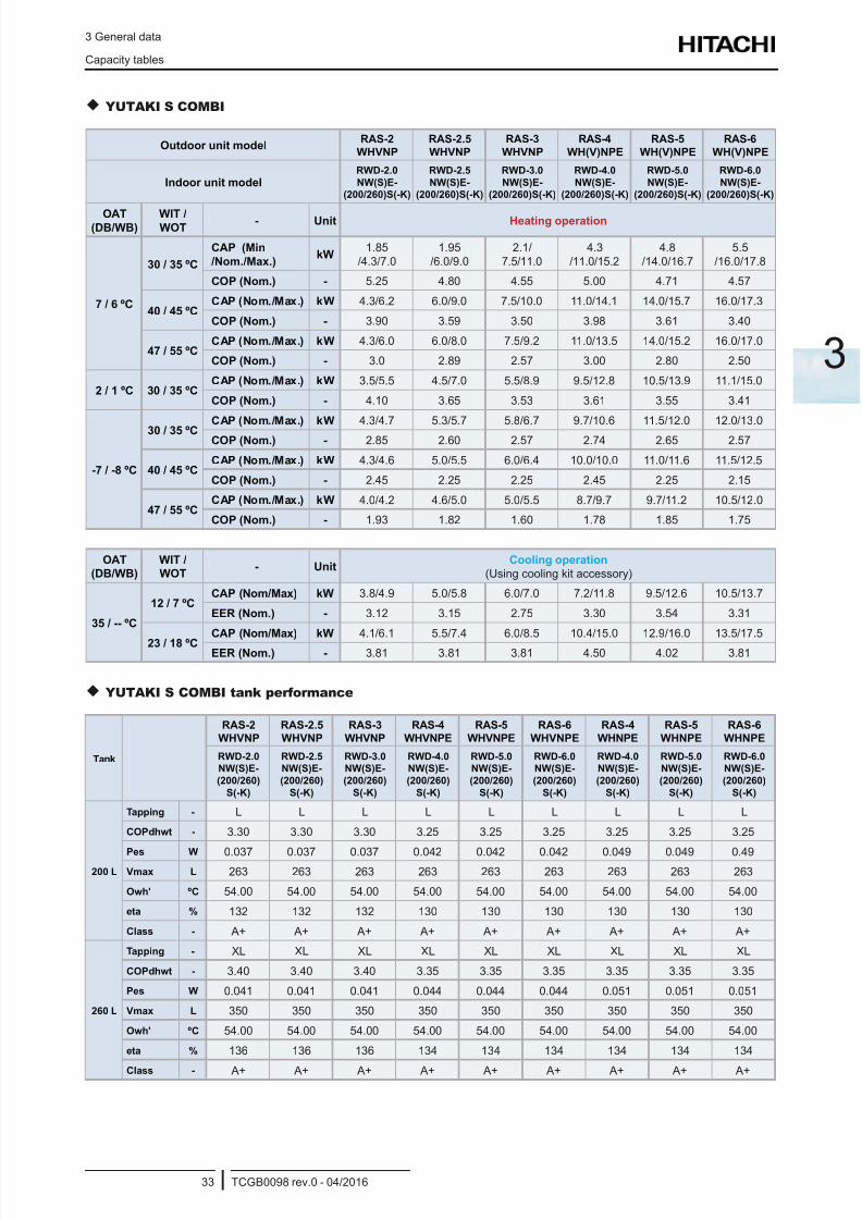
8/16/2019 Hitachi Yutaki Series 2016 Αντλίες θερμότητας
http://slidepdf.com/reader/full/hitachi-yutaki-series-2016- 43/256
3 General data
Capacity tables
TCGB0098 rev.0 - 04/201633
3
YUTAKI S COMBI
Outdoor unit modelRAS-2
WHVNP
RAS-2.5
WHVNP
RAS-3
WHVNP
RAS-4
WH(V)NPE
RAS-5
WH(V)NPE
RAS-6
WH(V)NPE
Indoor unit modelRWD-2.0
NW(S)E-
(200/260)S(-K)
RWD-2.5
NW(S)E-
(200/260)S(-K)
RWD-3.0
NW(S)E-
(200/260)S(-K)
RWD-4.0
NW(S)E-
(200/260)S(-K)
RWD-5.0
NW(S)E-
(200/260)S(-K)
RWD-6.0
NW(S)E-
(200/260)S(-K)
OAT(DB/WB)
WIT /WOT
- Unit Heating operation
7 / 6 ºC
30 / 35 ºC
CAP (Min
/Nom./Max.)kW
1.85
/4.3/7.0
1.95
/6.0/9.0
2.1/
7.5/11.0
4.3
/11.0/15.2
4.8
/14.0/16.7
5.5
/16.0/17.8
COP (Nom.) - 5.25 4.80 4.55 5.00 4.71 4.57
40 / 45 ºCCAP (Nom./Max.) kW 4.3/6.2 6.0/9.0 7.5/10.0 11.0/14.1 14.0/15.7 16.0/17.3
COP (Nom.) - 3.90 3.59 3.50 3.98 3.61 3.40
47 / 55 ºCCAP (Nom./Max.) kW 4.3/6.0 6.0/8.0 7.5/9.2 11.0/13.5 14.0/15.2 16.0/17.0
COP (Nom.) - 3.0 2.89 2.57 3.00 2.80 2.50
2 / 1 ºC 30 / 35 ºCCAP (Nom./Max.) kW 3.5/5.5 4.5/7.0 5.5/8.9 9.5/12.8 10.5/13.9 11.1/15.0
COP (Nom.) - 4.10 3.65 3.53 3.61 3.55 3.41
-7 / -8 ºC
30 / 35 ºCCAP (Nom./Max.) kW 4.3/4.7 5.3/5.7 5.8/6.7 9.7/10.6 11.5/12.0 12.0/13.0
COP (Nom.) - 2.85 2.60 2.57 2.74 2.65 2.57
40 / 45 ºCCAP (Nom./Max.) kW 4.3/4.6 5.0/5.5 6.0/6.4 10.0/10.0 11.0/11.6 11.5/12.5
COP (Nom.) - 2.45 2.25 2.25 2.45 2.25 2.15
47 / 55 ºCCAP (Nom./Max.) kW 4.0/4.2 4.6/5.0 5.0/5.5 8.7/9.7 9.7/11.2 10.5/12.0
COP (Nom.) - 1.93 1.82 1.60 1.78 1.85 1.75
OAT
(DB/WB)
WIT /
WOT- Unit
Cooling operation
(Using cooling kit accessory)
35 / -- ºC
12 / 7 ºCCAP (Nom/Max) kW 3.8/4.9 5.0/5.8 6.0/7.0 7.2/11.8 9.5/12.6 10.5/13.7
EER (Nom.) - 3.12 3.15 2.75 3.30 3.54 3.31
23 / 18 ºCCAP (Nom/Max) kW 4.1/6.1 5.5/7.4 6.0/8.5 10.4/15.0 12.9/16.0 13.5/17.5
EER (Nom.) - 3.81 3.81 3.81 4.50 4.02 3.81
YUTAKI S COMBI tank performance
Tank
RAS-2
WHVNP
RAS-2.5
WHVNP
RAS-3
WHVNP
RAS-4
WHVNPE
RAS-5
WHVNPE
RAS-6
WHVNPE
RAS-4
WHNPE
RAS-5
WHNPE
RAS-6
WHNPE
RWD-2.0
NW(S)E-
(200/260)
S(-K)
RWD-2.5
NW(S)E-
(200/260)
S(-K)
RWD-3.0
NW(S)E-
(200/260)
S(-K)
RWD-4.0
NW(S)E-
(200/260)
S(-K)
RWD-5.0
NW(S)E-
(200/260)
S(-K)
RWD-6.0
NW(S)E-
(200/260)
S(-K)
RWD-4.0
NW(S)E-
(200/260)
S(-K)
RWD-5.0
NW(S)E-
(200/260)
S(-K)
RWD-6.0
NW(S)E-
(200/260)
S(-K)
200 L
Tapping - L L L L L L L L L
COPdhwt - 3.30 3.30 3.30 3.25 3.25 3.25 3.25 3.25 3.25
Pes W 0.037 0.037 0.037 0.042 0.042 0.042 0.049 0.049 0.49Vmax L 263 263 263 263 263 263 263 263 263
Owh' ºC 54.00 54.00 54.00 54.00 54.00 54.00 54.00 54.00 54.00
eta % 132 132 132 130 130 130 130 130 130
Class - A+ A+ A+ A+ A+ A+ A+ A+ A+
260 L
Tapping - XL XL XL XL XL XL XL XL XL
COPdhwt - 3.40 3.40 3.40 3.35 3.35 3.35 3.35 3.35 3.35
Pes W 0.041 0.041 0.041 0.044 0.044 0.044 0.051 0.051 0.051
Vmax L 350 350 350 350 350 350 350 350 350
Owh' ºC 54.00 54.00 54.00 54.00 54.00 54.00 54.00 54.00 54.00
eta % 136 136 136 134 134 134 134 134 134
Class - A+ A+ A+ A+ A+ A+ A+ A+ A+
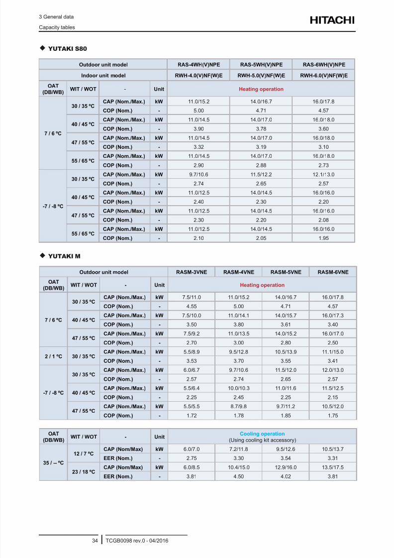
8/16/2019 Hitachi Yutaki Series 2016 Αντλίες θερμότητας
http://slidepdf.com/reader/full/hitachi-yutaki-series-2016- 44/256
3 General data
Capacity tables
TCGB0098 rev.0 - 04/201634
YUTAKI S80
Outdoor unit model RAS-4WH(V)NPE RAS-5WH(V)NPE RAS-6WH(V)NPE
Indoor unit model RWH-4.0(V)NF(W)E RWH-5.0(V)NF(W)E RWH-6.0(V)NF(W)E
OAT
(DB/WB)WIT / WOT - Unit Heating operation
7 / 6 ºC
30 / 35 ºCCAP (Nom./Max.) kW 11.0/15.2 14.0/16.7 16.0/17.8
COP (Nom.) - 5.00 4.71 4.57
40 / 45 ºCCAP (Nom./Max.) kW 11.0/14.5 14.0/17.0 16.0/18.0
COP (Nom.) - 3.90 3.78 3.60
47 / 55 ºCCAP (Nom./Max.) kW 11.0/14.5 14.0/17.0 16.0/18.0
COP (Nom.) - 3.32 3.19 3.10
55 / 65 ºCCAP (Nom./Max.) kW 11.0/14.5 14.0/17.0 16.0/18.0
COP (Nom.) - 2.90 2.88 2.73
-7 / -8 ºC
30 / 35 ºCCAP (Nom./Max.) kW 9.7/10.6 11.5/12.2 12.1/13.0
COP (Nom.) - 2.74 2.65 2.57
40 / 45 ºC CAP (Nom./Max.) kW 11.0/12.5 14.0/14.5 16.0/16.0COP (Nom.) - 2.40 2.30 2.20
47 / 55 ºCCAP (Nom./Max.) kW 11.0/12.5 14.0/14.5 16.0/16.0
COP (Nom.) - 2.30 2.20 2.08
55 / 65 ºCCAP (Nom./Max.) kW 11.0/12.5 14.0/14.5 16.0/16.0
COP (Nom.) - 2.10 2.05 1.95
YUTAKI M
Outdoor unit model RASM-3VNE RASM-4VNE RASM-5VNE RASM-6VNE
OAT
(DB/WB)WIT / WOT - Unit Heating operation
7 / 6 ºC
30 / 35 ºCCAP (Nom./Max.) kW 7.5/11.0 11.0/15.2 14.0/16.7 16.0/17.8
COP (Nom.) - 4.55 5.00 4.71 4.57
40 / 45 ºCCAP (Nom./Max.) kW 7.5/10.0 11.0/14.1 14.0/15.7 16.0/17.3
COP (Nom.) - 3.50 3.80 3.61 3.40
47 / 55 ºCCAP (Nom./Max.) kW 7.5/9.2 11.0/13.5 14.0/15.2 16.0/17.0
COP (Nom.) - 2.70 3.00 2.80 2.50
2 / 1 ºC 30 / 35 ºCCAP (Nom./Max.) kW 5.5/8.9 9.5/12.8 10.5/13.9 11.1/15.0
COP (Nom.) - 3.53 3.70 3.55 3.41
-7 / -8 ºC
30 / 35 ºCCAP (Nom./Max.) kW 6.0/6.7 9.7/10.6 11.5/12.0 12.0/13.0
COP (Nom.) - 2.57 2.74 2.65 2.57
40 / 45 ºCCAP (Nom./Max.) kW 5.5/6.4 10.0/10.3 11.0/11.6 11.5/12.5
COP (Nom.) - 2.25 2.45 2.25 2.15
47 / 55 ºCCAP (Nom./Max.) kW 5.5/5.5 8.7/9.8 9.7/11.2 10.5/12.0
COP (Nom.) - 1.72 1.78 1.85 1.75
OAT
(DB/WB)WIT / WOT - Unit
Cooling operation
(Using cooling kit accessory)
35 / -- ºC
12 / 7 ºCCAP (Nom/Max) kW 6.0/7.0 7.2/11.8 9.5/12.6 10.5/13.7
EER (Nom.) - 2.75 3.30 3.54 3.31
23 / 18 ºCCAP (Nom/Max) kW 6.0/8.5 10.4/15.0 12.9/16.0 13.5/17.5
EER (Nom.) - 3.81 4.50 4.02 3.81
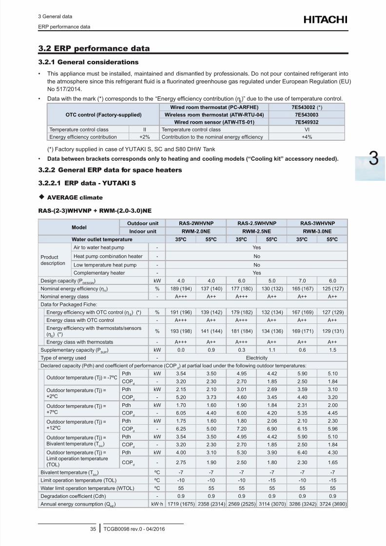
8/16/2019 Hitachi Yutaki Series 2016 Αντλίες θερμότητας
http://slidepdf.com/reader/full/hitachi-yutaki-series-2016- 45/256
3 General data
ERP performance data
TCGB0098 rev.0 - 04/201635
3
3.2 ERP performance data
3.2.1 General considerations
• This appliance must be installed, maintained and dismantled by professionals. Do not pour contained refrigerant into
the atmosphere since this refrigerant uid is a uorinated greenhouse gas regulated under European Regulation (EU)
No 517/2014.
• Data with the mark (*) corresponds to the “Energy efciency contribution (ηS)” due to the use of temperature control.
OTC control (Factory-supplied)
Wired room thermostat (PC-ARFHE) 7E543002 (*)
Wireless room thermostat (ATW-RTU-04) 7E543003
Wired room sensor (ATW-ITS-01) 7E549932
Temperature control class II Temperature control class VI
Energy efciency contribution +2% Contribution to the nominal energy efciency +4%
(*) Factory supplied in case of YUTAKI S, SC and S80 DHW Tank
• Data between brackets corresponds only to heating and cooling models (“Cooling kit” accessory needed).
3.2.2 General ERP data for space heaters
3.2.2.1 ERP data - YUTAKI S
AVERAGE climate
RAS-(2-3)WHVNP + RWM-(2.0-3.0)NE
ModelOutdoor unit RAS-2WHVNP RAS-2.5WHVNP RAS-3WHVNP
Indoor unit RWM-2.0NE RWM-2.5NE RWM-3.0NE
Water outlet temperature 35ºC 55ºC 35ºC 55ºC 35ºC 55ºC
Productdescription
Air to water heat pump - Yes
Heat pump combination heater - No
Low temperature heat pump - No
Complementary heater - Yes
Design capacity (PDESIGN
) kW 4.0 4.0 6.0 5.0 7.0 6.0
Nominal energy efciency (ηS) % 189 (194) 137 (140) 177 (180) 130 (132) 165 (167) 125 (127)
Nominal energy class - A+++ A++ A+++ A++ A++ A++
Data for Packaged Fiche:
Energy efciency with OTC control (ηS) (*) % 191 (196) 139 (142) 179 (182) 132 (134) 167 (169) 127 (129)
Energy class with OTC control - A+++ A++ A+++ A++ A++ A++
Energy efciency with thermostats/sensors
(ηS) (*)
% 193 (198) 141 (144) 181 (184) 134 (136) 169 (171) 129 (131)
Energy class with thermostats - A+++ A++ A+++ A++ A++ A++
Supplementary capacity (PSUP
) kW 0.0 0.9 0.3 1.1 0.6 1.5
Type of energy used - Electricity
Declared capacity (Pdh) and coefcient of performance (COPd) at partial load under the following outdoor temperatures:
Outdoor temperature (Tj) = -7ºCPdh kW 3.54 3.50 4.95 4.42 5.90 5.10
COPd - 3.20 2.30 2.70 1.85 2.50 1.84Outdoor temperature (Tj) =+2ºC
Pdh kW 2.15 2.10 3.01 2.69 3.59 3.10
COPd
- 5.20 3.73 4.60 3.45 4.40 3.20
Outdoor temperature (Tj) =+7ºC
Pdh kW 1.70 1.60 1.90 1.84 2.31 2.00
COPd
- 6.05 4.40 6.00 4.20 5.35 4.45
Outdoor temperature (Tj) =+12ºC
Pdh kW 1.75 1.60 1.80 2.06 2.10 2.30
COPd
- 6.25 5.00 7.20 6.90 6.15 5.96
Outdoor temperature (Tj) =Bivalent temperature (T
biv)
Pdh kW 3.54 3.50 4.95 4.42 5.90 5.10
COPd
- 3.20 2.30 2.70 1.85 2.50 1.84
Outdoor temperature (Tj) =Limit operation temperature(TOL)
Pdh kW 4.00 3.10 5.30 3.90 6.40 4.30
COPd
- 2.75 1.90 2.50 1.80 2.30 1.65
Bivalent temperature (Tbiv
) ºC -7 -7 -7 -7 -7 -7
Limit operation temperature (TOL) ºC -10 -10 -10 -15 -10 -15
Water limit operation temperature (WTOL) ºC 55 55 55 55 55 55
Degradation coefcient (Cdh) - 0.9 0.9 0.9 0.9 0.9 0.9
Annual energy consumption (QHE
) kW·h 1719 (1675) 2358 (2314) 2569 (2525) 3114 (3070) 3286 (3242) 3724 (3690)
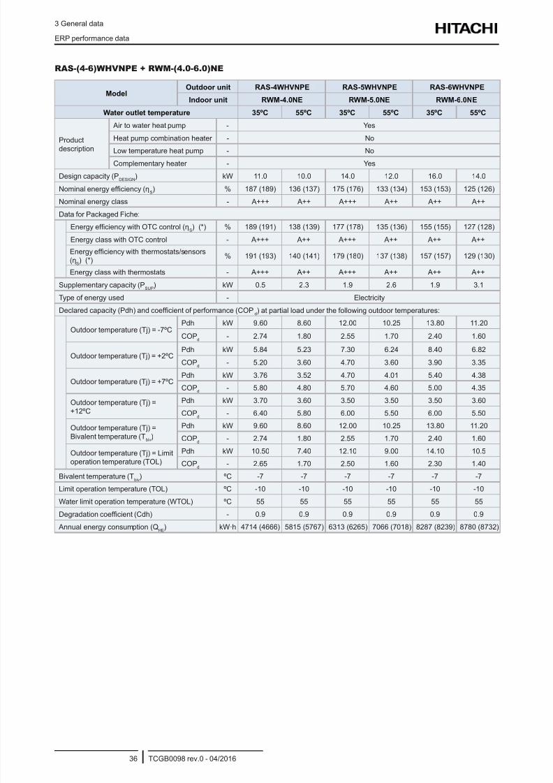
8/16/2019 Hitachi Yutaki Series 2016 Αντλίες θερμότητας
http://slidepdf.com/reader/full/hitachi-yutaki-series-2016- 46/256
3 General data
ERP performance data
TCGB0098 rev.0 - 04/201636
RAS-(4-6)WHVNPE + RWM-(4.0-6.0)NE
ModelOutdoor unit RAS-4WHVNPE RAS-5WHVNPE RAS-6WHVNPE
Indoor unit RWM-4.0NE RWM-5.0NE RWM-6.0NE
Water outlet temperature 35ºC 55ºC 35ºC 55ºC 35ºC 55ºC
Productdescription
Air to water heat pump - Yes
Heat pump combination heater - No
Low temperature heat pump - No
Complementary heater - Yes
Design capacity (PDESIGN
) kW 11.0 10.0 14.0 12.0 16.0 14.0
Nominal energy efciency (ηS) % 187 (189) 136 (137) 175 (176) 133 (134) 153 (153) 125 (126)
Nominal energy class - A+++ A++ A+++ A++ A++ A++
Data for Packaged Fiche:
Energy efciency with OTC control (ηS) (*) % 189 (191) 138 (139) 177 (178) 135 (136) 155 (155) 127 (128)
Energy class with OTC control - A+++ A++ A+++ A++ A++ A++
Energy efciency with thermostats/sensors
(ηS) (*)
% 191 (193) 140 (141) 179 (180) 137 (138) 157 (157) 129 (130)
Energy class with thermostats - A+++ A++ A+++ A++ A++ A++Supplementary capacity (P
SUP) kW 0.5 2.3 1.9 2.6 1.9 3.1
Type of energy used - Electricity
Declared capacity (Pdh) and coefcient of performance (COPd) at partial load under the following outdoor temperatures:
Outdoor temperature (Tj) = -7ºCPdh kW 9.60 8.60 12.00 10.25 13.80 11.20
COPd
- 2.74 1.80 2.55 1.70 2.40 1.60
Outdoor temperature (Tj) = +2ºCPdh kW 5.84 5.23 7.30 6.24 8.40 6.82
COPd
- 5.20 3.60 4.70 3.60 3.90 3.35
Outdoor temperature (Tj) = +7ºCPdh kW 3.76 3.52 4.70 4.01 5.40 4.38
COPd
- 5.80 4.80 5.70 4.60 5.00 4.35
Outdoor temperature (Tj) =
+12ºC
Pdh kW 3.70 3.60 3.50 3.50 3.50 3.60
COPd - 6.40 5.80 6.00 5.50 6.00 5.50
Outdoor temperature (Tj) =Bivalent temperature (T
biv)
Pdh kW 9.60 8.60 12.00 10.25 13.80 11.20
COPd
- 2.74 1.80 2.55 1.70 2.40 1.60
Outdoor temperature (Tj) = Limitoperation temperature (TOL)
Pdh kW 10.50 7.40 12.10 9.00 14.10 10.5
COPd
- 2.65 1.70 2.50 1.60 2.30 1.40
Bivalent temperature (Tbiv
) ºC -7 -7 -7 -7 -7 -7
Limit operation temperature (TOL) ºC -10 -10 -10 -10 -10 -10
Water limit operation temperature (WTOL) ºC 55 55 55 55 55 55
Degradation coefcient (Cdh) - 0.9 0.9 0.9 0.9 0.9 0.9
Annual energy consumption (QHE
) kW·h 4714 (4666) 5815 (5767) 6313 (6265) 7066 (7018) 8287 (8239) 8780 (8732)
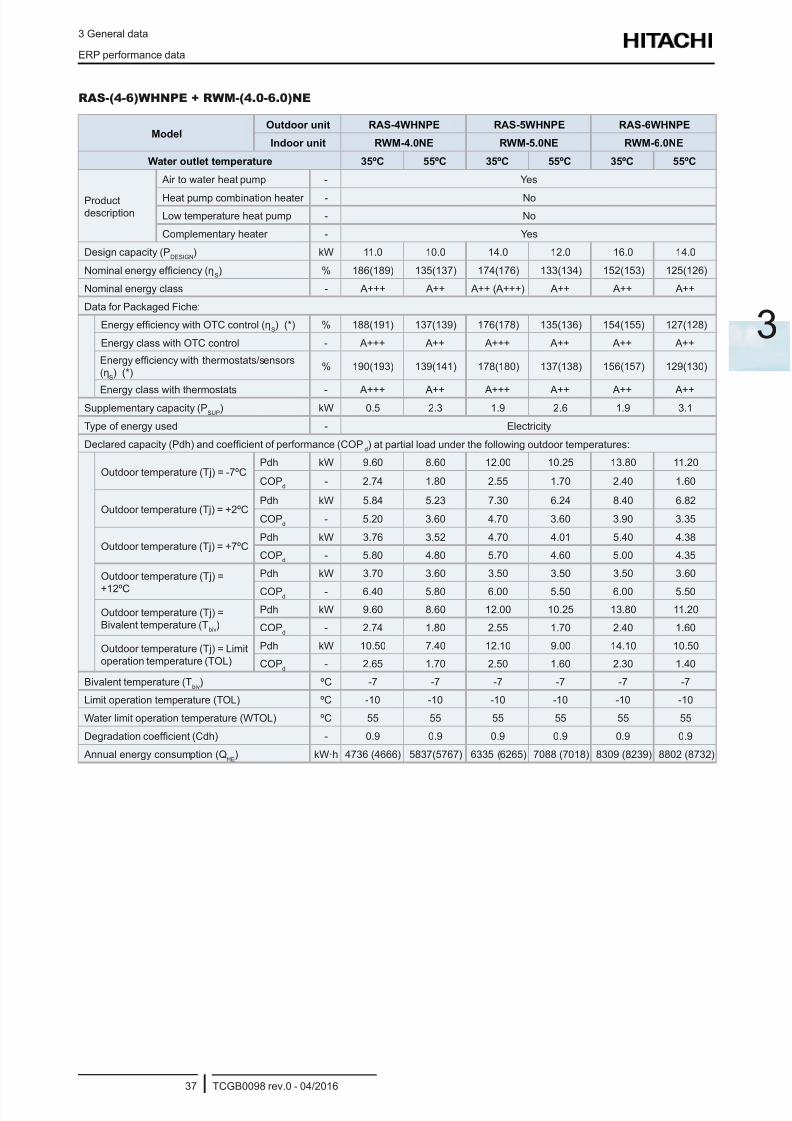
8/16/2019 Hitachi Yutaki Series 2016 Αντλίες θερμότητας
http://slidepdf.com/reader/full/hitachi-yutaki-series-2016- 47/256
3 General data
ERP performance data
TCGB0098 rev.0 - 04/201637
3
RAS-(4-6)WHNPE + RWM-(4.0-6.0)NE
ModelOutdoor unit RAS-4WHNPE RAS-5WHNPE RAS-6WHNPE
Indoor unit RWM-4.0NE RWM-5.0NE RWM-6.0NE
Water outlet temperature 35ºC 55ºC 35ºC 55ºC 35ºC 55ºC
Productdescription
Air to water heat pump - Yes
Heat pump combination heater - No
Low temperature heat pump - No
Complementary heater - Yes
Design capacity (PDESIGN
) kW 11.0 10.0 14.0 12.0 16.0 14.0
Nominal energy efciency (ηS) % 186(189) 135(137) 174(176) 133(134) 152(153) 125(126)
Nominal energy class - A+++ A++ A++ (A+++) A++ A++ A++
Data for Packaged Fiche:
Energy efciency with OTC control (ηS) (*) % 188(191) 137(139) 176(178) 135(136) 154(155) 127(128)
Energy class with OTC control - A+++ A++ A+++ A++ A++ A++
Energy efciency with thermostats/sensors
(ηS) (*)
% 190(193) 139(141) 178(180) 137(138) 156(157) 129(130)
Energy class with thermostats - A+++ A++ A+++ A++ A++ A++Supplementary capacity (P
SUP) kW 0.5 2.3 1.9 2.6 1.9 3.1
Type of energy used - Electricity
Declared capacity (Pdh) and coefcient of performance (COPd) at partial load under the following outdoor temperatures:
Outdoor temperature (Tj) = -7ºCPdh kW 9.60 8.60 12.00 10.25 13.80 11.20
COPd
- 2.74 1.80 2.55 1.70 2.40 1.60
Outdoor temperature (Tj) = +2ºCPdh kW 5.84 5.23 7.30 6.24 8.40 6.82
COPd
- 5.20 3.60 4.70 3.60 3.90 3.35
Outdoor temperature (Tj) = +7ºCPdh kW 3.76 3.52 4.70 4.01 5.40 4.38
COPd
- 5.80 4.80 5.70 4.60 5.00 4.35
Outdoor temperature (Tj) =
+12ºC
Pdh kW 3.70 3.60 3.50 3.50 3.50 3.60
COPd - 6.40 5.80 6.00 5.50 6.00 5.50
Outdoor temperature (Tj) =Bivalent temperature (T
biv)
Pdh kW 9.60 8.60 12.00 10.25 13.80 11.20
COPd
- 2.74 1.80 2.55 1.70 2.40 1.60
Outdoor temperature (Tj) = Limitoperation temperature (TOL)
Pdh kW 10.50 7.40 12.10 9.00 14.10 10.50
COPd
- 2.65 1.70 2.50 1.60 2.30 1.40
Bivalent temperature (Tbiv
) ºC -7 -7 -7 -7 -7 -7
Limit operation temperature (TOL) ºC -10 -10 -10 -10 -10 -10
Water limit operation temperature (WTOL) ºC 55 55 55 55 55 55
Degradation coefcient (Cdh) - 0.9 0.9 0.9 0.9 0.9 0.9
Annual energy consumption (QHE
) kW·h 4736 (4666) 5837(5767) 6335 (6265) 7088 (7018) 8309 (8239) 8802 (8732)
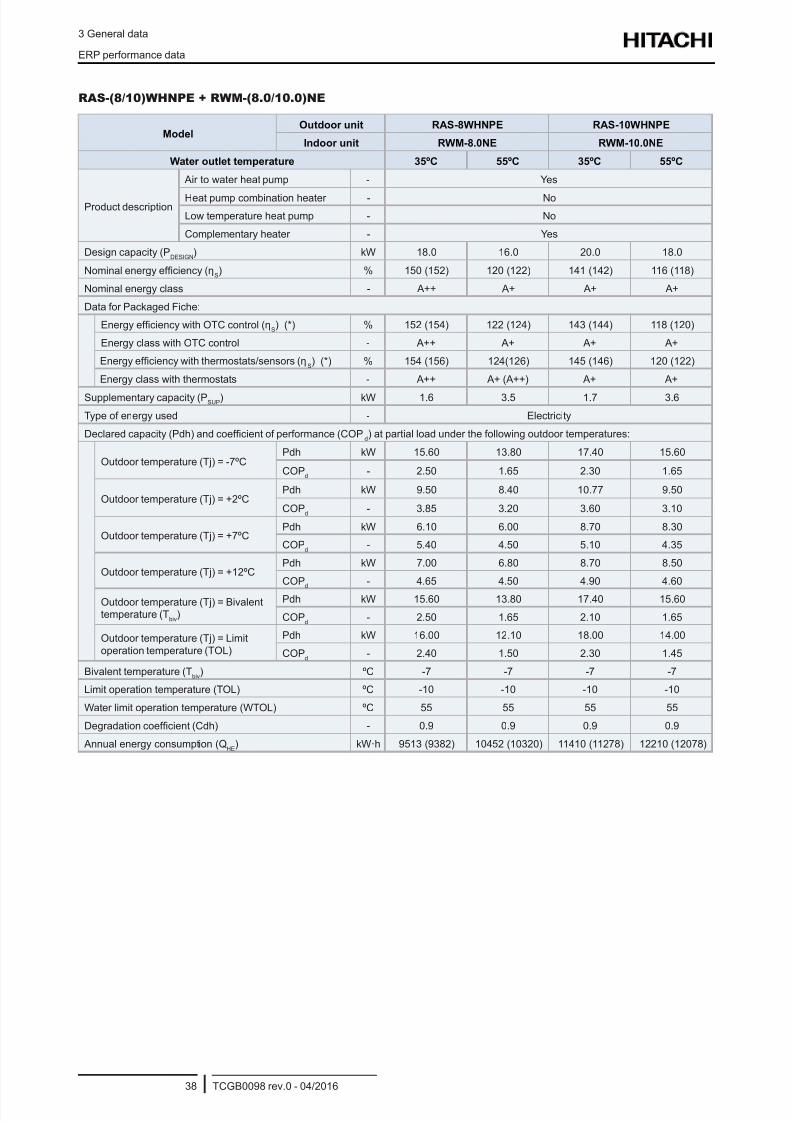
8/16/2019 Hitachi Yutaki Series 2016 Αντλίες θερμότητας
http://slidepdf.com/reader/full/hitachi-yutaki-series-2016- 48/256
3 General data
ERP performance data
TCGB0098 rev.0 - 04/201638
RAS-(8/10)WHNPE + RWM-(8.0/10.0)NE
ModelOutdoor unit RAS-8WHNPE RAS-10WHNPE
Indoor unit RWM-8.0NE RWM-10.0NE
Water outlet temperature 35ºC 55ºC 35ºC 55ºC
Product description
Air to water heat pump - Yes
Heat pump combination heater - No
Low temperature heat pump - No
Complementary heater - Yes
Design capacity (PDESIGN
) kW 18.0 16.0 20.0 18.0
Nominal energy efciency (ηS) % 150 (152) 120 (122) 141 (142) 116 (118)
Nominal energy class - A++ A+ A+ A+
Data for Packaged Fiche:
Energy efciency with OTC control (ηS) (*) % 152 (154) 122 (124) 143 (144) 118 (120)
Energy class with OTC control - A++ A+ A+ A+
Energy efciency with thermostats/sensors (ηS) (*) % 154 (156) 124(126) 145 (146) 120 (122)
Energy class with thermostats - A++ A+ (A++) A+ A+
Supplementary capacity (PSUP
) kW 1.6 3.5 1.7 3.6
Type of energy used - Electricity
Declared capacity (Pdh) and coefcient of performance (COPd) at partial load under the following outdoor temperatures:
Outdoor temperature (Tj) = -7ºCPdh kW 15.60 13.80 17.40 15.60
COPd
- 2.50 1.65 2.30 1.65
Outdoor temperature (Tj) = +2ºCPdh kW 9.50 8.40 10.77 9.50
COPd
- 3.85 3.20 3.60 3.10
Outdoor temperature (Tj) = +7ºCPdh kW 6.10 6.00 8.70 8.30
COPd
- 5.40 4.50 5.10 4.35
Outdoor temperature (Tj) = +12ºCPdh kW 7.00 6.80 8.70 8.50
COPd
- 4.65 4.50 4.90 4.60
Outdoor temperature (Tj) = Bivalenttemperature (T
biv)
Pdh kW 15.60 13.80 17.40 15.60
COPd
- 2.50 1.65 2.10 1.65
Outdoor temperature (Tj) = Limitoperation temperature (TOL)
Pdh kW 16.00 12.10 18.00 14.00
COPd
- 2.40 1.50 2.30 1.45
Bivalent temperature (Tbiv
) ºC -7 -7 -7 -7
Limit operation temperature (TOL) ºC -10 -10 -10 -10
Water limit operation temperature (WTOL) ºC 55 55 55 55
Degradation coefcient (Cdh) - 0.9 0.9 0.9 0.9
Annual energy consumption (QHE
) kW·h 9513 (9382) 10452 (10320) 11410 (11278) 12210 (12078)
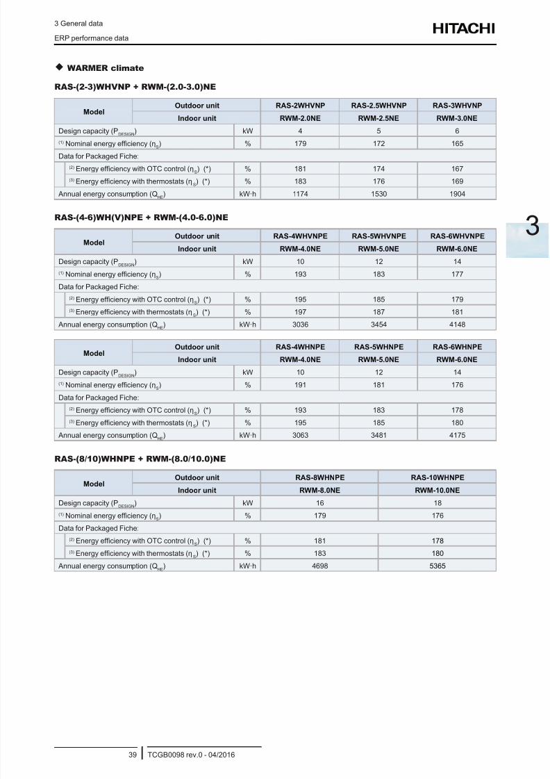
8/16/2019 Hitachi Yutaki Series 2016 Αντλίες θερμότητας
http://slidepdf.com/reader/full/hitachi-yutaki-series-2016- 49/256
3 General data
ERP performance data
TCGB0098 rev.0 - 04/201639
3
WARMER climate
RAS-(2-3)WHVNP + RWM-(2.0-3.0)NE
ModelOutdoor unit RAS-2WHVNP RAS-2.5WHVNP RAS-3WHVNP
Indoor unit RWM-2.0NE RWM-2.5NE RWM-3.0NE
Design capacity (PDESIGN
) kW 4 5 6
(1) Nominal energy efciency (ηS) % 179 172 165
Data for Packaged Fiche:
(2) Energy efciency with OTC control (ηS) (*) % 181 174 167
(3) Energy efciency with thermostats (ηS) (*) % 183 176 169
Annual energy consumption (QHE
) kW·h 1174 1530 1904
RAS-(4-6)WH(V)NPE + RWM-(4.0-6.0)NE
ModelOutdoor unit RAS-4WHVNPE RAS-5WHVNPE RAS-6WHVNPE
Indoor unit RWM-4.0NE RWM-5.0NE RWM-6.0NE
Design capacity (PDESIGN
) kW 10 12 14
(1) Nominal energy efciency (ηS) % 193 183 177
Data for Packaged Fiche:
(2) Energy efciency with OTC control (ηS) (*) % 195 185 179
(3) Energy efciency with thermostats (ηS) (*) % 197 187 181
Annual energy consumption (QHE
) kW·h 3036 3454 4148
ModelOutdoor unit RAS-4WHNPE RAS-5WHNPE RAS-6WHNPE
Indoor unit RWM-4.0NE RWM-5.0NE RWM-6.0NE
Design capacity (PDESIGN
) kW 10 12 14
(1) Nominal energy efciency (ηS) % 191 181 176
Data for Packaged Fiche:
(2) Energy efciency with OTC control (ηS) (*) % 193 183 178(3) Energy efciency with thermostats (η
S) (*) % 195 185 180
Annual energy consumption (QHE
) kW·h 3063 3481 4175
RAS-(8/10)WHNPE + RWM-(8.0/10.0)NE
ModelOutdoor unit RAS-8WHNPE RAS-10WHNPE
Indoor unit RWM-8.0NE RWM-10.0NE
Design capacity (PDESIGN
) kW 16 18
(1) Nominal energy efciency (ηS) % 179 176
Data for Packaged Fiche:
(2) Energy efciency with OTC control (ηS
) (*) % 181 178
(3) Energy efciency with thermostats (ηS) (*) % 183 180
Annual energy consumption (QHE
) kW·h 4698 5365
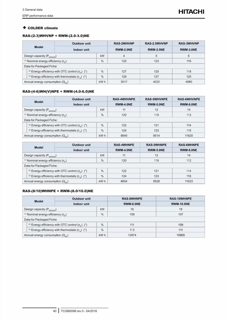
8/16/2019 Hitachi Yutaki Series 2016 Αντλίες θερμότητας
http://slidepdf.com/reader/full/hitachi-yutaki-series-2016- 50/256
3 General data
ERP performance data
TCGB0098 rev.0 - 04/201640
COLDER climate
RAS-(2-3)WHVNP + RWM-(2.0-3.0)NE
ModelOutdoor unit RAS-2WHVNP RAS-2.5WHVNP RAS-3WHVNP
Indoor unit RWM-2.0NE RWM-2.5NE RWM-3.0NE
Design capacity (PDESIGN) kW 4 5 6(1) Nominal energy efciency (η
S) % 125 123 116
Data for Packaged Fiche:
(2) Energy efciency with OTC control (ηS) (*) % 127 125 118
(3) Energy efciency with thermostats (ηS) (*) % 129 127 120
Annual energy consumption (QHE
) kW·h 3017 4022 4980
RAS-(4-6)WH(V)NPE + RWM-(4.0-6.0)NE
ModelOutdoor unit RAS-4WHVNPE RAS-5WHVNPE RAS-6WHVNPE
Indoor unit RWM-4.0NE RWM-5.0NE RWM-6.0NE
Design capacity (PDESIGN
) kW 11 12 14
(1) Nominal energy efciency (ηS) % 120 119 112
Data for Packaged Fiche:
(2) Energy efciency with OTC control (ηS) (*) % 122 121 114
(3) Energy efciency with thermostats (ηS) (*) % 124 123 116
Annual energy consumption (QHE
) kW·h 8640 9514 11620
ModelOutdoor unit RAS-4WHNPE RAS-5WHNPE RAS-6WHNPE
Indoor unit RWM-4.0NE RWM-5.0NE RWM-6.0NE
Design capacity (PDESIGN
) kW 11 12 14
(1) Nominal energy efciency (ηS) % 120 119 112
Data for Packaged Fiche:
(2) Energy efciency with OTC control (ηS) (*) % 122 121 114
(3) Energy efciency with thermostats (ηS) (*) % 124 123 116
Annual energy consumption (QHE
) kW·h 8654 9528 11633
RAS-(8/10)WHNPE + RWM-(8.0/10.0)NE
ModelOutdoor unit RAS-8WHNPE RAS-10WHNPE
Indoor unit RWM-8.0NE RWM-10.0NE
Design capacity (PDESIGN
) kW 16 18
(1) Nominal energy efciency (ηS) % 109 107
Data for Packaged Fiche:
(2) Energy efciency with OTC control (ηS) (*) % 111 109(3) Energy efciency with thermostats (η
S) (*) % 113 111
Annual energy consumption (QHE
) kW·h 13974 15905
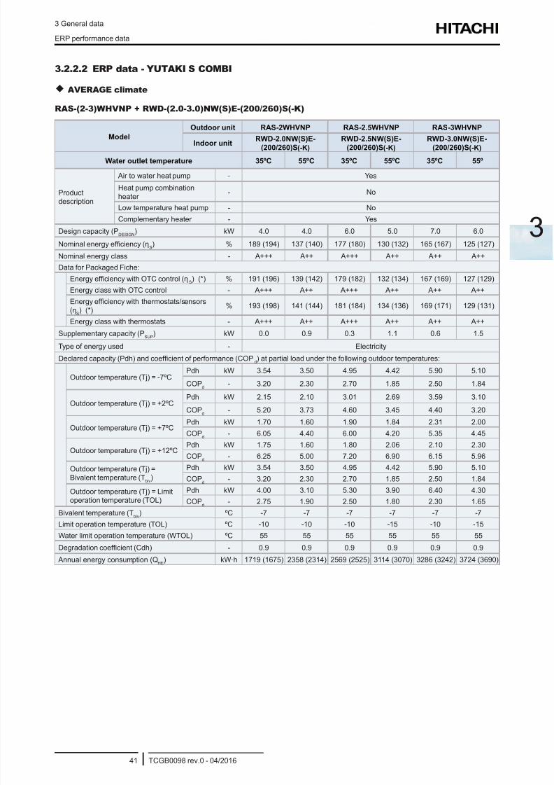
8/16/2019 Hitachi Yutaki Series 2016 Αντλίες θερμότητας
http://slidepdf.com/reader/full/hitachi-yutaki-series-2016- 51/256
3 General data
ERP performance data
TCGB0098 rev.0 - 04/201641
3
3.2.2.2 ERP data - YUTAKI S COMBI
AVERAGE climate
RAS-(2-3)WHVNP + RWD-(2.0-3.0)NW(S)E-(200/260)S(-K)
Model
Outdoor unit RAS-2WHVNP RAS-2.5WHVNP RAS-3WHVNP
Indoor unit RWD-2.0NW(S)E-(200/260)S(-K)
RWD-2.5NW(S)E-(200/260)S(-K)
RWD-3.0NW(S)E-(200/260)S(-K)
Water outlet temperature 35ºC 55ºC 35ºC 55ºC 35ºC 55º
Productdescription
Air to water heat pump - Yes
Heat pump combinationheater
- No
Low temperature heat pump - No
Complementary heater - Yes
Design capacity (PDESIGN
) kW 4.0 4.0 6.0 5.0 7.0 6.0
Nominal energy efciency (ηS) % 189 (194) 137 (140) 177 (180) 130 (132) 165 (167) 125 (127)
Nominal energy class - A+++ A++ A+++ A++ A++ A++
Data for Packaged Fiche:
Energy efciency with OTC control (ηS) (*) % 191 (196) 139 (142) 179 (182) 132 (134) 167 (169) 127 (129)
Energy class with OTC control - A+++ A++ A+++ A++ A++ A++
Energy efciency with thermostats/sensors
(ηS) (*)
% 193 (198) 141 (144) 181 (184) 134 (136) 169 (171) 129 (131)
Energy class with thermostats - A+++ A++ A+++ A++ A++ A++
Supplementary capacity (PSUP
) kW 0.0 0.9 0.3 1.1 0.6 1.5
Type of energy used - Electricity
Declared capacity (Pdh) and coefcient of performance (COPd) at partial load under the following outdoor temperatures:
Outdoor temperature (Tj) = -7ºCPdh kW 3.54 3.50 4.95 4.42 5.90 5.10
COPd
- 3.20 2.30 2.70 1.85 2.50 1.84
Outdoor temperature (Tj) = +2ºCPdh kW 2.15 2.10 3.01 2.69 3.59 3.10
COPd - 5.20 3.73 4.60 3.45 4.40 3.20
Outdoor temperature (Tj) = +7ºCPdh kW 1.70 1.60 1.90 1.84 2.31 2.00
COPd
- 6.05 4.40 6.00 4.20 5.35 4.45
Outdoor temperature (Tj) = +12ºCPdh kW 1.75 1.60 1.80 2.06 2.10 2.30
COPd
- 6.25 5.00 7.20 6.90 6.15 5.96
Outdoor temperature (Tj) =Bivalent temperature (T
biv)
Pdh kW 3.54 3.50 4.95 4.42 5.90 5.10
COPd
- 3.20 2.30 2.70 1.85 2.50 1.84
Outdoor temperature (Tj) = Limitoperation temperature (TOL)
Pdh kW 4.00 3.10 5.30 3.90 6.40 4.30
COPd
- 2.75 1.90 2.50 1.80 2.30 1.65
Bivalent temperature (Tbiv
) ºC -7 -7 -7 -7 -7 -7
Limit operation temperature (TOL) ºC -10 -10 -10 -15 -10 -15
Water limit operation temperature (WTOL) ºC 55 55 55 55 55 55
Degradation coefcient (Cdh) - 0.9 0.9 0.9 0.9 0.9 0.9 Annual energy consumption (Q
HE) kW·h 1719 (1675) 2358 (2314) 2569 (2525) 3114 (3070) 3286 (3242) 3724 (3690)
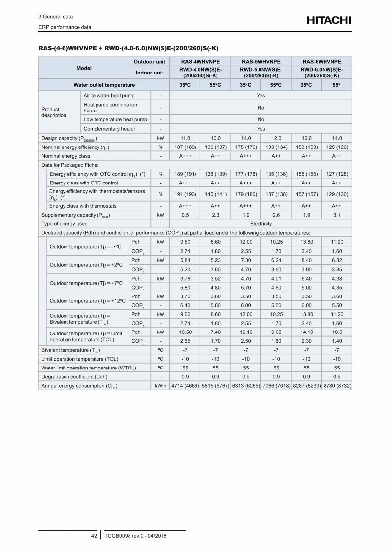
8/16/2019 Hitachi Yutaki Series 2016 Αντλίες θερμότητας
http://slidepdf.com/reader/full/hitachi-yutaki-series-2016- 52/256
3 General data
ERP performance data
TCGB0098 rev.0 - 04/201642
RAS-(4-6)WHVNPE + RWD-(4.0-6.0)NW(S)E-(200/260)S(-K)
Model
Outdoor unit RAS-4WHVNPE RAS-5WHVNPE RAS-6WHVNPE
Indoor unitRWD-4.0NW(S)E-
(200/260)S(-K)
RWD-5.0NW(S)E-
(200/260)S(-K)
RWD-6.0NW(S)E-
(200/260)S(-K)
Water outlet temperature 35ºC 55ºC 35ºC 55ºC 35ºC 55º
Productdescription
Air to water heat pump - YesHeat pump combinationheater
- No
Low temperature heat pump - No
Complementary heater - Yes
Design capacity (PDESIGN
) kW 11.0 10.0 14.0 12.0 16.0 14.0
Nominal energy efciency (ηS) % 187 (189) 136 (137) 175 (176) 133 (134) 153 (153) 125 (126)
Nominal energy class - A+++ A++ A+++ A++ A++ A++
Data for Packaged Fiche:
Energy efciency with OTC control (ηS) (*) % 189 (191) 138 (139) 177 (178) 135 (136) 155 (155) 127 (128)
Energy class with OTC control - A+++ A++ A+++ A++ A++ A++
Energy efciency with thermostats/sensors(ηS) (*) % 191 (193) 140 (141) 179 (180) 137 (138) 157 (157) 129 (130)
Energy class with thermostats - A+++ A++ A+++ A++ A++ A++
Supplementary capacity (PSUP
) kW 0.5 2.3 1.9 2.6 1.9 3.1
Type of energy used - Electricity
Declared capacity (Pdh) and coefcient of performance (COPd) at partial load under the following outdoor temperatures:
Outdoor temperature (Tj) = -7ºCPdh kW 9.60 8.60 12.00 10.25 13.80 11.20
COPd
- 2.74 1.80 2.55 1.70 2.40 1.60
Outdoor temperature (Tj) = +2ºCPdh kW 5.84 5.23 7.30 6.24 8.40 6.82
COPd
- 5.20 3.60 4.70 3.60 3.90 3.35
Outdoor temperature (Tj) = +7ºCPdh kW 3.76 3.52 4.70 4.01 5.40 4.38
COPd
- 5.80 4.80 5.70 4.60 5.00 4.35
Outdoor temperature (Tj) = +12ºCPdh kW 3.70 3.60 3.50 3.50 3.50 3.60
COPd
- 6.40 5.80 6.00 5.50 6.00 5.50
Outdoor temperature (Tj) =Bivalent temperature (T
biv)
Pdh kW 9.60 8.60 12.00 10.25 13.80 11.20
COPd
- 2.74 1.80 2.55 1.70 2.40 1.60
Outdoor temperature (Tj) = Limitoperation temperature (TOL)
Pdh kW 10.50 7.40 12.10 9.00 14.10 10.5
COPd
- 2.65 1.70 2.50 1.60 2.30 1.40
Bivalent temperature (Tbiv
) ºC -7 -7 -7 -7 -7 -7
Limit operation temperature (TOL) ºC -10 -10 -10 -10 -10 -10
Water limit operation temperature (WTOL) ºC 55 55 55 55 55 55
Degradation coefcient (Cdh) - 0.9 0.9 0.9 0.9 0.9 0.9
Annual energy consumption (QHE) kW·h 4714 (4666) 5815 (5767) 6313 (6265) 7066 (7018) 8287 (8239) 8780 (8732)
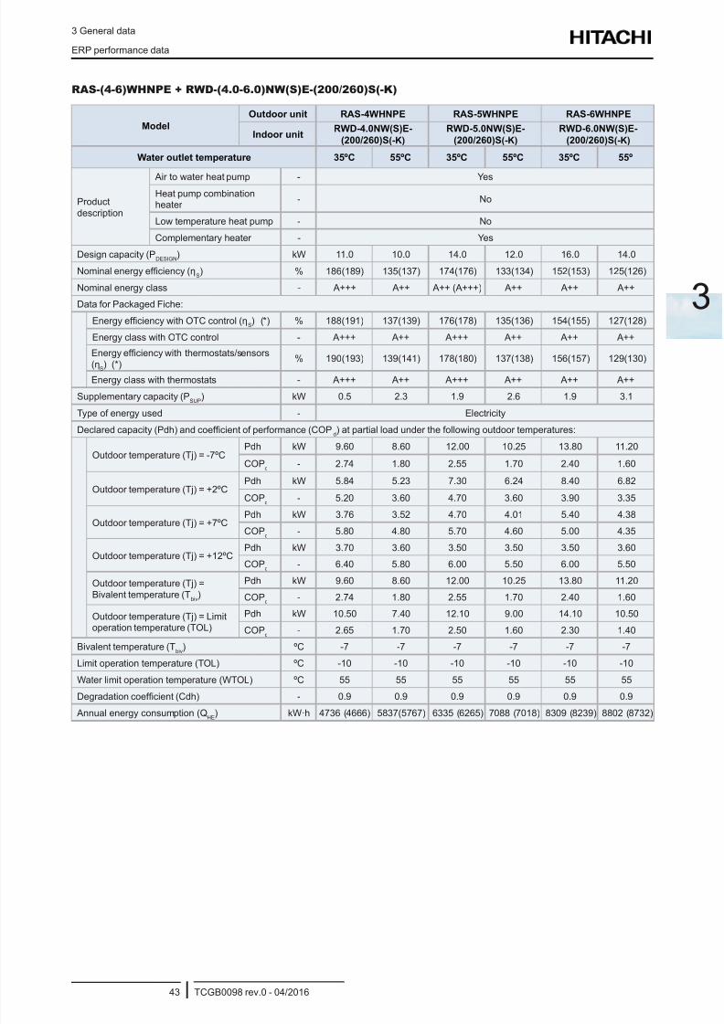
8/16/2019 Hitachi Yutaki Series 2016 Αντλίες θερμότητας
http://slidepdf.com/reader/full/hitachi-yutaki-series-2016- 53/256
3 General data
ERP performance data
TCGB0098 rev.0 - 04/201643
3
RAS-(4-6)WHNPE + RWD-(4.0-6.0)NW(S)E-(200/260)S(-K)
Model
Outdoor unit RAS-4WHNPE RAS-5WHNPE RAS-6WHNPE
Indoor unitRWD-4.0NW(S)E-
(200/260)S(-K)
RWD-5.0NW(S)E-
(200/260)S(-K)
RWD-6.0NW(S)E-
(200/260)S(-K)
Water outlet temperature 35ºC 55ºC 35ºC 55ºC 35ºC 55º
Productdescription
Air to water heat pump - YesHeat pump combinationheater
- No
Low temperature heat pump - No
Complementary heater - Yes
Design capacity (PDESIGN
) kW 11.0 10.0 14.0 12.0 16.0 14.0
Nominal energy efciency (ηS) % 186(189) 135(137) 174(176) 133(134) 152(153) 125(126)
Nominal energy class - A+++ A++ A++ (A+++) A++ A++ A++
Data for Packaged Fiche:
Energy efciency with OTC control (ηS) (*) % 188(191) 137(139) 176(178) 135(136) 154(155) 127(128)
Energy class with OTC control - A+++ A++ A+++ A++ A++ A++
Energy efciency with thermostats/sensors
(ηS) (*) % 190(193) 139(141) 178(180) 137(138) 156(157) 129(130)
Energy class with thermostats - A+++ A++ A+++ A++ A++ A++
Supplementary capacity (PSUP
) kW 0.5 2.3 1.9 2.6 1.9 3.1
Type of energy used - Electricity
Declared capacity (Pdh) and coefcient of performance (COPd) at partial load under the following outdoor temperatures:
Outdoor temperature (Tj) = -7ºCPdh kW 9.60 8.60 12.00 10.25 13.80 11.20
COPd
- 2.74 1.80 2.55 1.70 2.40 1.60
Outdoor temperature (Tj) = +2ºCPdh kW 5.84 5.23 7.30 6.24 8.40 6.82
COPd
- 5.20 3.60 4.70 3.60 3.90 3.35
Outdoor temperature (Tj) = +7ºCPdh kW 3.76 3.52 4.70 4.01 5.40 4.38
COPd
- 5.80 4.80 5.70 4.60 5.00 4.35
Outdoor temperature (Tj) = +12ºCPdh kW 3.70 3.60 3.50 3.50 3.50 3.60
COPd
- 6.40 5.80 6.00 5.50 6.00 5.50
Outdoor temperature (Tj) =Bivalent temperature (T
biv)
Pdh kW 9.60 8.60 12.00 10.25 13.80 11.20
COPd
- 2.74 1.80 2.55 1.70 2.40 1.60
Outdoor temperature (Tj) = Limitoperation temperature (TOL)
Pdh kW 10.50 7.40 12.10 9.00 14.10 10.50
COPd
- 2.65 1.70 2.50 1.60 2.30 1.40
Bivalent temperature (Tbiv
) ºC -7 -7 -7 -7 -7 -7
Limit operation temperature (TOL) ºC -10 -10 -10 -10 -10 -10
Water limit operation temperature (WTOL) ºC 55 55 55 55 55 55
Degradation coefcient (Cdh) - 0.9 0.9 0.9 0.9 0.9 0.9
Annual energy consumption (QHE) kW·h 4736 (4666) 5837(5767) 6335 (6265) 7088 (7018) 8309 (8239) 8802 (8732)
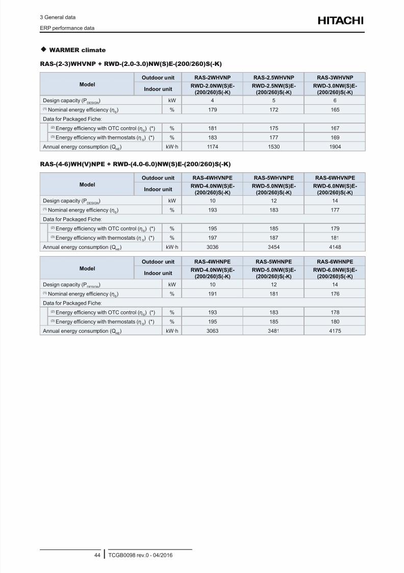
8/16/2019 Hitachi Yutaki Series 2016 Αντλίες θερμότητας
http://slidepdf.com/reader/full/hitachi-yutaki-series-2016- 54/256
3 General data
ERP performance data
TCGB0098 rev.0 - 04/201644
WARMER climate
RAS-(2-3)WHVNP + RWD-(2.0-3.0)NW(S)E-(200/260)S(-K)
Model
Outdoor unit RAS-2WHVNP RAS-2.5WHVNP RAS-3WHVNP
Indoor unitRWD-2.0NW(S)E-
(200/260)S(-K)
RWD-2.5NW(S)E-
(200/260)S(-K)
RWD-3.0NW(S)E-
(200/260)S(-K)
Design capacity (PDESIGN) kW 4 5 6(1) Nominal energy efciency (η
S) % 179 172 165
Data for Packaged Fiche:
(2) Energy efciency with OTC control (ηS) (*) % 181 175 167
(3) Energy efciency with thermostats (ηS) (*) % 183 177 169
Annual energy consumption (QHE
) kW·h 1174 1530 1904
RAS-(4-6)WH(V)NPE + RWD-(4.0-6.0)NW(S)E-(200/260)S(-K)
Model
Outdoor unit RAS-4WHVNPE RAS-5WHVNPE RAS-6WHVNPE
Indoor unitRWD-4.0NW(S)E-
(200/260)S(-K)
RWD-5.0NW(S)E-
(200/260)S(-K)
RWD-6.0NW(S)E-
(200/260)S(-K)
Design capacity (PDESIGN) kW 10 12 14(1) Nominal energy efciency (η
S) % 193 183 177
Data for Packaged Fiche:
(2) Energy efciency with OTC control (ηS) (*) % 195 185 179
(3) Energy efciency with thermostats (ηS) (*) % 197 187 181
Annual energy consumption (QHE
) kW·h 3036 3454 4148
Model
Outdoor unit RAS-4WHNPE RAS-5WHNPE RAS-6WHNPE
Indoor unitRWD-4.0NW(S)E-
(200/260)S(-K)
RWD-5.0NW(S)E-
(200/260)S(-K)
RWD-6.0NW(S)E-
(200/260)S(-K)
Design capacity (PDESIGN
) kW 10 12 14
(1) Nominal energy efciency (ηS) % 191 181 176
Data for Packaged Fiche:
(2) Energy efciency with OTC control (ηS) (*) % 193 183 178
(3) Energy efciency with thermostats (ηS) (*) % 195 185 180
Annual energy consumption (QHE
) kW·h 3063 3481 4175
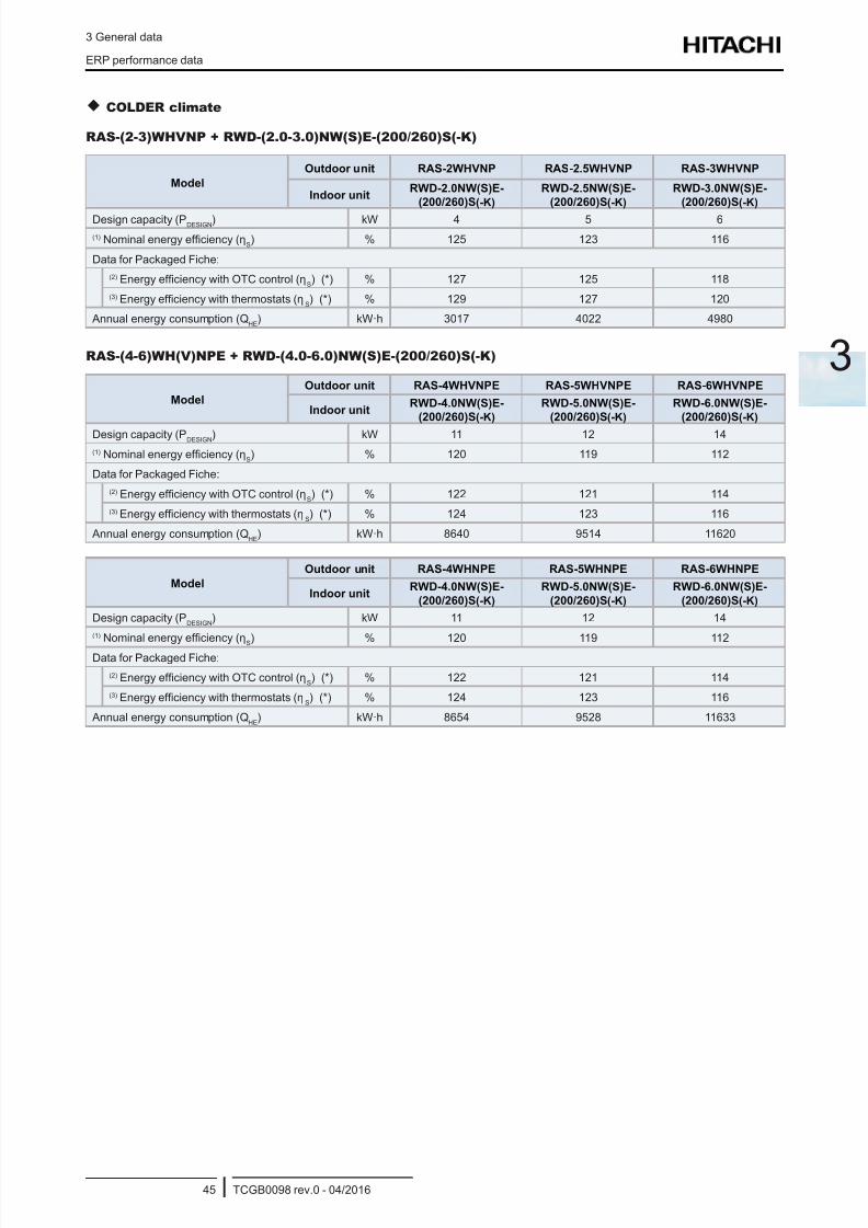
8/16/2019 Hitachi Yutaki Series 2016 Αντλίες θερμότητας
http://slidepdf.com/reader/full/hitachi-yutaki-series-2016- 55/256
3 General data
ERP performance data
TCGB0098 rev.0 - 04/201645
3
COLDER climate
RAS-(2-3)WHVNP + RWD-(2.0-3.0)NW(S)E-(200/260)S(-K)
Model
Outdoor unit RAS-2WHVNP RAS-2.5WHVNP RAS-3WHVNP
Indoor unitRWD-2.0NW(S)E-
(200/260)S(-K)
RWD-2.5NW(S)E-
(200/260)S(-K)
RWD-3.0NW(S)E-
(200/260)S(-K)
Design capacity (PDESIGN
) kW 4 5 6
(1) Nominal energy efciency (ηS) % 125 123 116
Data for Packaged Fiche:
(2) Energy efciency with OTC control (ηS) (*) % 127 125 118
(3) Energy efciency with thermostats (ηS) (*) % 129 127 120
Annual energy consumption (QHE
) kW·h 3017 4022 4980
RAS-(4-6)WH(V)NPE + RWD-(4.0-6.0)NW(S)E-(200/260)S(-K)
Model
Outdoor unit RAS-4WHVNPE RAS-5WHVNPE RAS-6WHVNPE
Indoor unitRWD-4.0NW(S)E-
(200/260)S(-K)
RWD-5.0NW(S)E-
(200/260)S(-K)
RWD-6.0NW(S)E-
(200/260)S(-K)
Design capacity (PDESIGN
) kW 11 12 14
(1) Nominal energy efciency (ηS) % 120 119 112
Data for Packaged Fiche:
(2) Energy efciency with OTC control (ηS) (*) % 122 121 114
(3) Energy efciency with thermostats (ηS) (*) % 124 123 116
Annual energy consumption (QHE
) kW·h 8640 9514 11620
Model
Outdoor unit RAS-4WHNPE RAS-5WHNPE RAS-6WHNPE
Indoor unitRWD-4.0NW(S)E-
(200/260)S(-K)
RWD-5.0NW(S)E-
(200/260)S(-K)
RWD-6.0NW(S)E-
(200/260)S(-K)
Design capacity (PDESIGN
) kW 11 12 14
(1) Nominal energy efciency (ηS
) % 120 119 112
Data for Packaged Fiche:
(2) Energy efciency with OTC control (ηS) (*) % 122 121 114
(3) Energy efciency with thermostats (ηS) (*) % 124 123 116
Annual energy consumption (QHE
) kW·h 8654 9528 11633
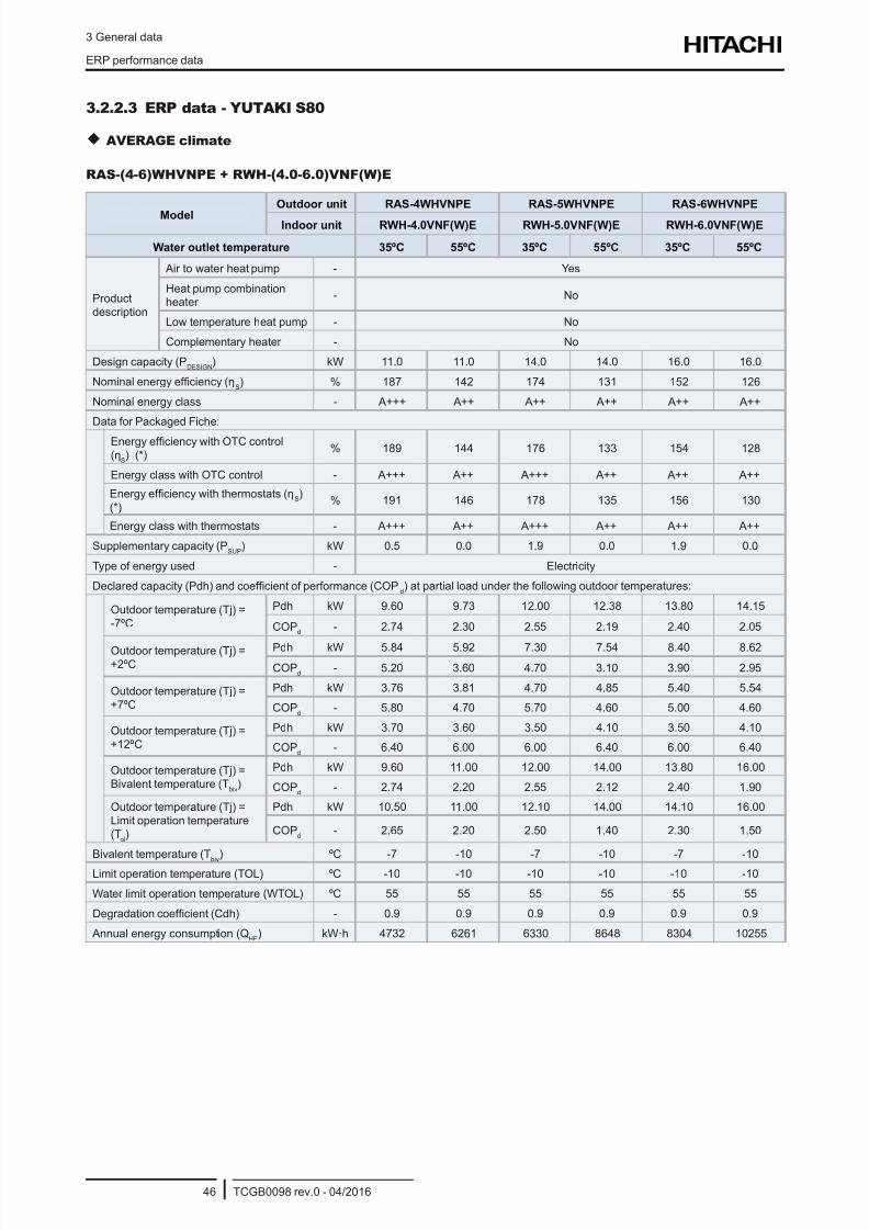
8/16/2019 Hitachi Yutaki Series 2016 Αντλίες θερμότητας
http://slidepdf.com/reader/full/hitachi-yutaki-series-2016- 56/256
3 General data
ERP performance data
TCGB0098 rev.0 - 04/201646
3.2.2.3 ERP data - YUTAKI S80
AVERAGE climate
RAS-(4-6)WHVNPE + RWH-(4.0-6.0)VNF(W)E
Model
Outdoor unit RAS-4WHVNPE RAS-5WHVNPE RAS-6WHVNPE
Indoor unit RWH-4.0VNF(W)E RWH-5.0VNF(W)E RWH-6.0VNF(W)E
Water outlet temperature 35ºC 55ºC 35ºC 55ºC 35ºC 55ºC
Productdescription
Air to water heat pump - Yes
Heat pump combinationheater
- No
Low temperature heat pump - No
Complementary heater - No
Design capacity (PDESIGN
) kW 11.0 11.0 14.0 14.0 16.0 16.0
Nominal energy efciency (ηS) % 187 142 174 131 152 126
Nominal energy class - A+++ A++ A++ A++ A++ A++
Data for Packaged Fiche:
Energy efciency with OTC control
(ηS) (*)
% 189 144 176 133 154 128
Energy class with OTC control - A+++ A++ A+++ A++ A++ A++
Energy efciency with thermostats (ηS)
(*)% 191 146 178 135 156 130
Energy class with thermostats - A+++ A++ A+++ A++ A++ A++
Supplementary capacity (PSUP
) kW 0.5 0.0 1.9 0.0 1.9 0.0
Type of energy used - Electricity
Declared capacity (Pdh) and coefcient of performance (COPd) at partial load under the following outdoor temperatures:
Outdoor temperature (Tj) =-7ºC
Pdh kW 9.60 9.73 12.00 12.38 13.80 14.15
COPd
- 2.74 2.30 2.55 2.19 2.40 2.05
Outdoor temperature (Tj) =+2ºC
Pdh kW 5.84 5.92 7.30 7.54 8.40 8.62
COPd
- 5.20 3.60 4.70 3.10 3.90 2.95
Outdoor temperature (Tj) =+7ºC
Pdh kW 3.76 3.81 4.70 4.85 5.40 5.54
COPd
- 5.80 4.70 5.70 4.60 5.00 4.60
Outdoor temperature (Tj) =+12ºC
Pdh kW 3.70 3.60 3.50 4.10 3.50 4.10
COPd
- 6.40 6.00 6.00 6.40 6.00 6.40
Outdoor temperature (Tj) =Bivalent temperature (T
biv)
Pdh kW 9.60 11.00 12.00 14.00 13.80 16.00
COPd
- 2.74 2.20 2.55 2.12 2.40 1.90
Outdoor temperature (Tj) =Limit operation temperature(T
ol)
Pdh kW 10.50 11.00 12.10 14.00 14.10 16.00
COPd
- 2.65 2.20 2.50 1.40 2.30 1.50
Bivalent temperature (Tbiv
) ºC -7 -10 -7 -10 -7 -10
Limit operation temperature (TOL) ºC -10 -10 -10 -10 -10 -10
Water limit operation temperature (WTOL) ºC 55 55 55 55 55 55
Degradation coefcient (Cdh) - 0.9 0.9 0.9 0.9 0.9 0.9
Annual energy consumption (QHE
) kW·h 4732 6261 6330 8648 8304 10255

8/16/2019 Hitachi Yutaki Series 2016 Αντλίες θερμότητας
http://slidepdf.com/reader/full/hitachi-yutaki-series-2016- 57/256
3 General data
ERP performance data
TCGB0098 rev.0 - 04/201647
3
RAS-(4-6)WHNPE + RWH-(4.0-6.0)NF(W)E
ModelOutdoor unit RAS-4WHNPE RAS-5WHNPE RAS-6WHNPE
Indoor unit RWH-4.0NF(W)E RWH-5.0NF(W)E RWH-6.0NF(W)E
Water outlet temperature 35ºC 55ºC 35ºC 55ºC 35ºC 55ºC
Productdescription
Air to water heat pump - Yes
Heat pump combination heater - No
Low temperature heat pump - No
Complementary heater - No
Design capacity (PDESIGN
) kW 11.0 11.0 14.0 14.0 16.0 16.0
Nominal energy efciency (ηS) % 183 140 171 129 150 125
Nominal energy class - A+++ A++ A++ A++ A++ A++
Data for Packaged Fiche:
Energy efciency with OTC control (ηS)
(*)% 185 142 173 131 152 127
Energy class with OTC control - A+++ A++ A++ A++ A++ A++
Energy efciency with thermostats (ηS) (*) % 187 144 176 134 154 129
Energy class with thermostats - A+++ A++ A+++ A++ A++ A++
Supplementary capacity (PSUP
) kW 0.5 0.0 1.5 0.0 1.5 0.0
Type of energy used - Electricity
Declared capacity (Pdh) and coefcient of performance (COPd) at partial load under the following outdoor temperatures:
Outdoor temperature (Tj) = -7ºCPdh kW 9.60 9.73 12.00 12.38 13.80 14.15
COPd
- 2.74 2.30 2.55 2.19 2.40 2.05
Outdoor temperature (Tj) = +2ºCPdh kW 5.84 5.92 7.30 7.54 8.40 8.62
COPd
- 5.20 3.60 4.70 3.10 3.90 2.95
Outdoor temperature (Tj) = +7ºCPdh kW 3.76 3.81 4.70 4.85 5.40 5.54
COPd
- 5.80 4.70 5.70 4.60 5.00 4.60
Outdoor temperature (Tj) =+12ºC
Pdh kW 3.70 3.60 3.50 4.10 3.50 4.10
COPd
- 6.40 6.00 6.00 6.40 6.00 6.40
Outdoor temperature (Tj) =Bivalent temperature (T
biv)
Pdh kW 9.60 11.00 12.00 14.00 13.80 16.00
COPd
- 2.74 2.20 2.55 2.12 2.40 1.90
Outdoor temperature (Tj) = Limitoperation temperature (TOL)
Pdh kW 10.50 11.00 12.10 14.00 14.10 16.00
COPd
- 2.65 2.20 2.50 1.40 2.30 1.50
Bivalent temperature (Tbiv
) ºC -7 -10 -7 -10 -7 -10
Limit operation temperature (TOL) ºC -10 -10 -10 -10 -10 -10
Water limit operation temperature (WTOL) ºC 55 55 55 55 55 55
Degradation coefcient (Cdh) - 0.9 0.9 0.9 0.9 0.9 0.9
Annual energy consumption (QHE
) kW·h 4828 6360 6426 8747 8401 10335
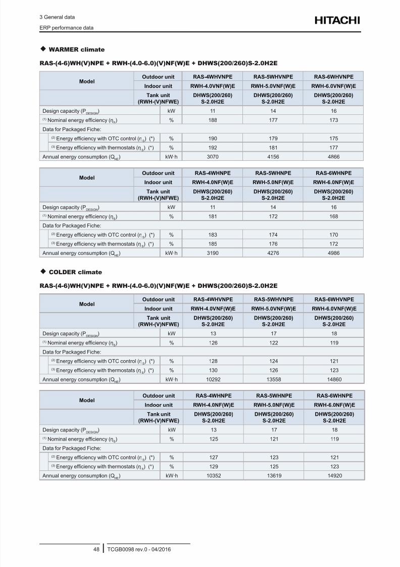
8/16/2019 Hitachi Yutaki Series 2016 Αντλίες θερμότητας
http://slidepdf.com/reader/full/hitachi-yutaki-series-2016- 58/256
3 General data
ERP performance data
TCGB0098 rev.0 - 04/201648
WARMER climate
RAS-(4-6)WH(V)NPE + RWH-(4.0-6.0)(V)NF(W)E + DHWS(200/260)S-2.0H2E
ModelOutdoor unit RAS-4WHVNPE RAS-5WHVNPE RAS-6WHVNPE
Indoor unit RWH-4.0VNF(W)E RWH-5.0VNF(W)E RWH-6.0VNF(W)E
Tank unit
(RWH-(V)NFWE)
DHWS(200/260)
S-2.0H2E
DHWS(200/260)
S-2.0H2E
DHWS(200/260)
S-2.0H2E
Design capacity (PDESIGN
) kW 11 14 16
(1) Nominal energy efciency (ηS) % 188 177 173
Data for Packaged Fiche:
(2) Energy efciency with OTC control (ηS) (*) % 190 179 175
(3) Energy efciency with thermostats (ηS) (*) % 192 181 177
Annual energy consumption (QHE
) kW·h 3070 4156 4866
ModelOutdoor unit RAS-4WHNPE RAS-5WHNPE RAS-6WHNPE
Indoor unit RWH-4.0NF(W)E RWH-5.0NF(W)E RWH-6.0NF(W)E
Tank unit
(RWH-(V)NFWE)
DHWS(200/260)
S-2.0H2E
DHWS(200/260)
S-2.0H2E
DHWS(200/260)
S-2.0H2E
Design capacity (PDESIGN
) kW 11 14 16
(1) Nominal energy efciency (ηS) % 181 172 168
Data for Packaged Fiche:
(2) Energy efciency with OTC control (ηS) (*) % 183 174 170
(3) Energy efciency with thermostats (ηS) (*) % 185 176 172
Annual energy consumption (QHE
) kW·h 3190 4276 4986
COLDER climate
RAS-(4-6)WH(V)NPE + RWH-(4.0-6.0)(V)NF(W)E + DHWS(200/260)S-2.0H2E
ModelOutdoor unit RAS-4WHVNPE RAS-5WHVNPE RAS-6WHVNPE
Indoor unit RWH-4.0VNF(W)E RWH-5.0VNF(W)E RWH-6.0VNF(W)E
Tank unit
(RWH-(V)NFWE)
DHWS(200/260)
S-2.0H2E
DHWS(200/260)
S-2.0H2E
DHWS(200/260)
S-2.0H2E
Design capacity (PDESIGN
) kW 13 17 18
(1) Nominal energy efciency (ηS) % 126 122 119
Data for Packaged Fiche:
(2) Energy efciency with OTC control (ηS) (*) % 128 124 121
(3) Energy efciency with thermostats (ηS) (*) % 130 126 123
Annual energy consumption (QHE
) kW·h 10292 13558 14860
Model Outdoor unit RAS-4WHNPE RAS-5WHNPE RAS-6WHNPEIndoor unit RWH-4.0NF(W)E RWH-5.0NF(W)E RWH-6.0NF(W)E
Tank unit
(RWH-(V)NFWE)
DHWS(200/260)
S-2.0H2E
DHWS(200/260)
S-2.0H2E
DHWS(200/260)
S-2.0H2E
Design capacity (PDESIGN
) kW 13 17 18
(1) Nominal energy efciency (ηS) % 125 121 119
Data for Packaged Fiche:
(2) Energy efciency with OTC control (ηS) (*) % 127 123 121
(3) Energy efciency with thermostats (ηS) (*) % 129 125 123
Annual energy consumption (QHE
) kW·h 10352 13619 14920

8/16/2019 Hitachi Yutaki Series 2016 Αντλίες θερμότητας
http://slidepdf.com/reader/full/hitachi-yutaki-series-2016- 59/256
3 General data
ERP performance data
TCGB0098 rev.0 - 04/201649
3
3.2.2.4 ERP data - YUTAKI M
AVERAGE climate
RASM-(3-6)VNE
Model RASM-3VNE RASM-4VNE RASM-5VNE RASM-6VNE
Water outlet temperature 35ºC 55ºC 35ºC 55ºC 35ºC 55ºC 35ºC 55ºC
Productdescription
Air to water heat pump - Yes
Heat pump combinationheater
- No
Low temperature heatpump
- No
Complementary heater - No
Design capacity (PDESIGN
) kW 7.0 6.0 11.0 10.0 14.0 12.0 16.0 14.0
Nominal energy efciency (ηS) % 164 (167) 125 (127) 187 (189) 136 (137) 175 (176) 133 (134)
153(153)
125(126)
Nominal energy class - A++ A++ A+++ A++ A+++ A++ A++ A++
Data for Packaged Fiche:
Energy efciency with OTC control
(ηS) (*)
% 166 (169) 127 (129) 189 (191) 138 (139) 177 (178) 135 (136)155
(155)127
(128)
Energy class with OTC control - A++ A++ A+++ A++ A+++ A++ A++ A++
Energy efciency with thermostats
(ηS) (*)
% 168 (171) 129 (131) 191 (193) 140 (141) 179 (180) 137 (138)157
(157)129
(130)
Energy class with thermostats - A++ A++ A+++ A++ A+++ A++ A++ A++
Supplementary capacity (PSUP
) kW 0.6 0.6 0.5 1.2 1.9 1.5 1.9 2.3
Type of energy used - Electricity
Declared capacity (Pdh) and coefcient of performance (COPd) at partial load under the following outdoor temperatures:
Outdoor temperature (Tj)= -7ºC
Pdh kW 5.90 5.10 9.60 8.60 12.00 10.25 13.80 11.20
COPd
- 2.50 1.84 2.74 1.80 2.55 1.70 2.40 1.60
Outdoor temperature (Tj)= +2ºC
Pdh kW 3.59 3.10 5.84 5.23 7.30 6.24 8.40 6.82
COPd
- 4.40 3.20 5.20 3.60 4.70 3.60 3.90 3.35
Outdoor temperature (Tj)= +7ºC
Pdh kW 2.31 2.00 3.76 3.52 4.70 4.01 5.40 4.38
COPd
- 5.35 4.45 5.80 4.80 5.70 4.60 5.00 4.35
Outdoor temperature (Tj)= +12ºC
Pdh kW 2.10 2.30 3.70 3.60 3.50 3.50 3.50 3.60
COPd
- 6.15 5.96 6.40 5.80 6.00 5.50 6.00 5.50
Outdoor temperature (Tj) =Bivalent temperature (T
biv)
Pdh kW 5.90 5.10 9.60 8.60 12.00 10.25 13.80 11.20
COPd
- 2.50 1.84 2.74 1.80 2.55 1.70 2.40 1.60
Outdoor temperature (Tj) =Limit operation temperature(TOL)
Pdh kW 6.40 5.20 10.50 8.80 12.10 10.50 14.10 11.70
COPd
- 2.30 1.65 2.65 1.90 2.50 1.70 2.30 1.55
Bivalent temperature (Tbiv
) ºC -7 -7 -7 -7 -7 -7 -7 -7
Limit operation temperature (TOL) ºC -10 -15 -10 -10 -10 -10 -10 -10
Water limit operation temperature(WTOL)
ºC 55 55 55 55 55 55 55 55
Degradation coefcient (Cdh) - 0.9 0.9 0.9 0.9 0.9 0.9 0.9 0.9
Annual energy consumption (QHE
) kW·h3298
(3242)3726
(3671)4714
(4666)5786
(5738)6313
(6265)7042
(6994)8287
(8239)8170
(8122)
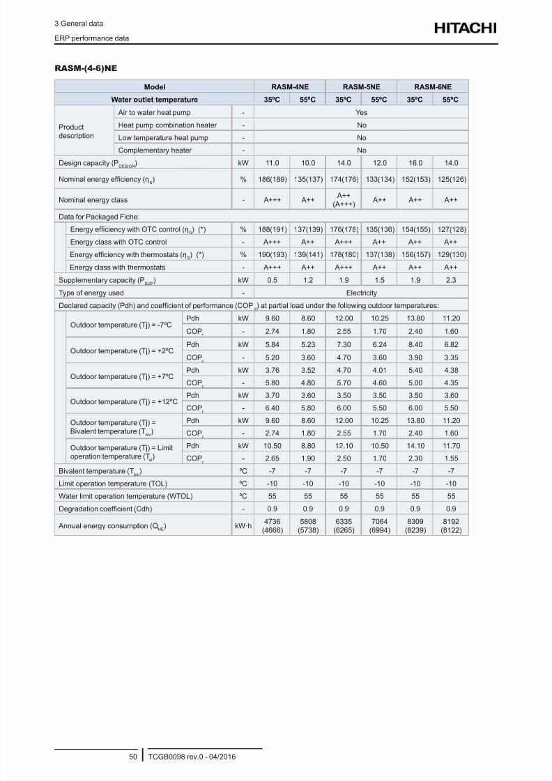
8/16/2019 Hitachi Yutaki Series 2016 Αντλίες θερμότητας
http://slidepdf.com/reader/full/hitachi-yutaki-series-2016- 60/256
3 General data
ERP performance data
TCGB0098 rev.0 - 04/201650
RASM-(4-6)NE
Model RASM-4NE RASM-5NE RASM-6NE
Water outlet temperature 35ºC 55ºC 35ºC 55ºC 35ºC 55ºC
Product
description
Air to water heat pump - Yes
Heat pump combination heater - No
Low temperature heat pump - No
Complementary heater - No
Design capacity (PDESIGN
) kW 11.0 10.0 14.0 12.0 16.0 14.0
Nominal energy efciency (ηS) % 186(189) 135(137) 174(176) 133(134) 152(153) 125(126)
Nominal energy class - A+++ A++ A++
(A+++) A++ A++ A++
Data for Packaged Fiche:
Energy efciency with OTC control (ηS) (*) % 188(191) 137(139) 176(178) 135(136) 154(155) 127(128)
Energy class with OTC control - A+++ A++ A+++ A++ A++ A++
Energy efciency with thermostats (ηS) (*) % 190(193) 139(141) 178(180) 137(138) 156(157) 129(130)
Energy class with thermostats - A+++ A++ A+++ A++ A++ A++
Supplementary capacity (PSUP
) kW 0.5 1.2 1.9 1.5 1.9 2.3
Type of energy used - Electricity
Declared capacity (Pdh) and coefcient of performance (COPd) at partial load under the following outdoor temperatures:
Outdoor temperature (Tj) = -7ºCPdh kW 9.60 8.60 12.00 10.25 13.80 11.20
COPd
- 2.74 1.80 2.55 1.70 2.40 1.60
Outdoor temperature (Tj) = +2ºCPdh kW 5.84 5.23 7.30 6.24 8.40 6.82
COPd
- 5.20 3.60 4.70 3.60 3.90 3.35
Outdoor temperature (Tj) = +7ºCPdh kW 3.76 3.52 4.70 4.01 5.40 4.38
COPd
- 5.80 4.80 5.70 4.60 5.00 4.35
Outdoor temperature (Tj) = +12ºCPdh kW 3.70 3.60 3.50 3.50 3.50 3.60
COPd - 6.40 5.80 6.00 5.50 6.00 5.50
Outdoor temperature (Tj) =Bivalent temperature (T
biv)
Pdh kW 9.60 8.60 12.00 10.25 13.80 11.20
COPd
- 2.74 1.80 2.55 1.70 2.40 1.60
Outdoor temperature (Tj) = Limitoperation temperature (T
ol)
Pdh kW 10.50 8.80 12.10 10.50 14.10 11.70
COPd
- 2.65 1.90 2.50 1.70 2.30 1.55
Bivalent temperature (Tbiv
) ºC -7 -7 -7 -7 -7 -7
Limit operation temperature (TOL) ºC -10 -10 -10 -10 -10 -10
Water limit operation temperature (WTOL) ºC 55 55 55 55 55 55
Degradation coefcient (Cdh) - 0.9 0.9 0.9 0.9 0.9 0.9
Annual energy consumption (QHE
) kW·h4736
(4666)5808
(5738)6335
(6265)7064
(6994)8309
(8239)8192
(8122)
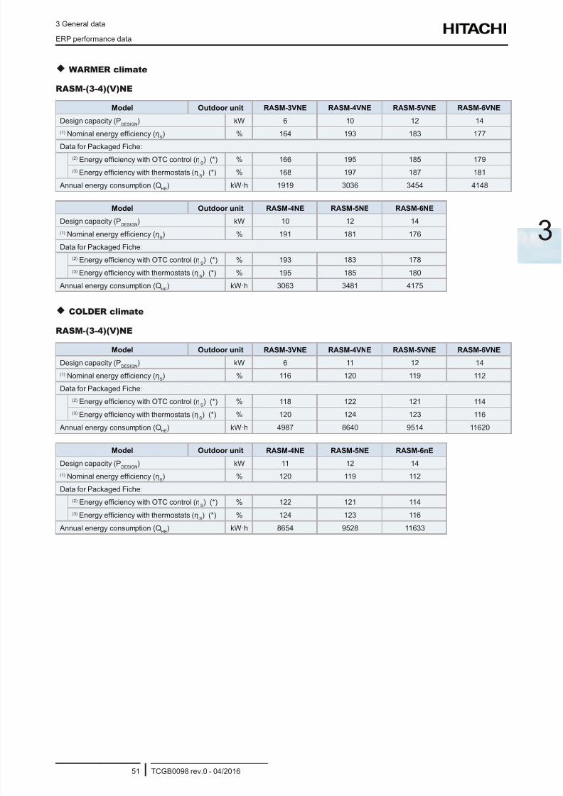
8/16/2019 Hitachi Yutaki Series 2016 Αντλίες θερμότητας
http://slidepdf.com/reader/full/hitachi-yutaki-series-2016- 61/256
3 General data
ERP performance data
TCGB0098 rev.0 - 04/201651
3
WARMER climate
RASM-(3-4)(V)NE
Model Outdoor unit RASM-3VNE RASM-4VNE RASM-5VNE RASM-6VNE
Design capacity (PDESIGN
) kW 6 10 12 14
(1) Nominal energy efciency (ηS
) % 164 193 183 177
Data for Packaged Fiche:
(2) Energy efciency with OTC control (ηS) (*) % 166 195 185 179
(3) Energy efciency with thermostats (ηS) (*) % 168 197 187 181
Annual energy consumption (QHE
) kW·h 1919 3036 3454 4148
Model Outdoor unit RASM-4NE RASM-5NE RASM-6NE
Design capacity (PDESIGN
) kW 10 12 14
(1) Nominal energy efciency (ηS) % 191 181 176
Data for Packaged Fiche:
(2) Energy efciency with OTC control (ηS) (*) % 193 183 178
(3) Energy efciency with thermostats (ηS) (*) % 195 185 180
Annual energy consumption (QHE
) kW·h 3063 3481 4175
COLDER climate
RASM-(3-4)(V)NE
Model Outdoor unit RASM-3VNE RASM-4VNE RASM-5VNE RASM-6VNE
Design capacity (PDESIGN
) kW 6 11 12 14
(1) Nominal energy efciency (ηS) % 116 120 119 112
Data for Packaged Fiche:
(2) Energy efciency with OTC control (ηS) (*) % 118 122 121 114
(3)
Energy efciency with thermostats (ηS) (*) % 120 124 123 116 Annual energy consumption (Q
HE) kW·h 4987 8640 9514 11620
Model Outdoor unit RASM-4NE RASM-5NE RASM-6nE
Design capacity (PDESIGN
) kW 11 12 14
(1) Nominal energy efciency (ηS) % 120 119 112
Data for Packaged Fiche:
(2) Energy efciency with OTC control (ηS) (*) % 122 121 114
(3) Energy efciency with thermostats (ηS) (*) % 124 123 116
Annual energy consumption (QHE
) kW·h 8654 9528 11633
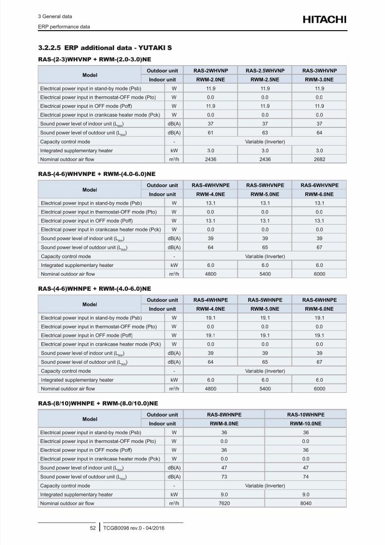
8/16/2019 Hitachi Yutaki Series 2016 Αντλίες θερμότητας
http://slidepdf.com/reader/full/hitachi-yutaki-series-2016- 62/256
3 General data
ERP performance data
TCGB0098 rev.0 - 04/201652
3.2.2.5 ERP additional data - YUTAKI S
RAS-(2-3)WHVNP + RWM-(2.0-3.0)NE
ModelOutdoor unit RAS-2WHVNP RAS-2.5WHVNP RAS-3WHVNP
Indoor unit RWM-2.0NE RWM-2.5NE RWM-3.0NE
Electrical power input in stand-by mode (Psb) W 11.9 11.9 11.9
Electrical power input in thermostat-OFF mode (Pto) W 0.0 0.0 0.0
Electrical power input in OFF mode (Poff) W 11.9 11.9 11.9
Electrical power input in crankcase heater mode (Pck) W 0.0 0.0 0.0
Sound power level of indoor unit (LWA
) dB(A) 37 37 37
Sound power level of outdoor unit (LWA
) dB(A) 61 63 64
Capacity control mode - Variable (Inverter)
Integrated supplementary heater kW 3.0 3.0 3.0
Nominal outdoor air ow m3/h 2436 2436 2682
RAS-(4-6)WHVNPE + RWM-(4.0-6.0)NE
Model
Outdoor unit RAS-4WHVNPE RAS-5WHVNPE RAS-6WHVNPE
Indoor unit RWM-4.0NE RWM-5.0NE RWM-6.0NE
Electrical power input in stand-by mode (Psb) W 13.1 13.1 13.1
Electrical power input in thermostat-OFF mode (Pto) W 0.0 0.0 0.0
Electrical power input in OFF mode (Poff) W 13.1 13.1 13.1
Electrical power input in crankcase heater mode (Pck) W 0.0 0.0 0.0
Sound power level of indoor unit (LWA
) dB(A) 39 39 39
Sound power level of outdoor unit (LWA
) dB(A) 64 65 67
Capacity control mode - Variable (Inverter)
Integrated supplementary heater kW 6.0 6.0 6.0
Nominal outdoor air ow m3/h 4800 5400 6000
RAS-(4-6)WHNPE + RWM-(4.0-6.0)NE
ModelOutdoor unit RAS-4WHNPE RAS-5WHNPE RAS-6WHNPE
Indoor unit RWM-4.0NE RWM-5.0NE RWM-6.0NE
Electrical power input in stand-by mode (Psb) W 19.1 19.1 19.1
Electrical power input in thermostat-OFF mode (Pto) W 0.0 0.0 0.0
Electrical power input in OFF mode (Poff) W 19.1 19.1 19.1
Electrical power input in crankcase heater mode (Pck) W 0.0 0.0 0.0
Sound power level of indoor unit (LWA
) dB(A) 39 39 39
Sound power level of outdoor unit (LWA
) dB(A) 64 65 67
Capacity control mode - Variable (Inverter)
Integrated supplementary heater kW 6.0 6.0 6.0Nominal outdoor air ow m3/h 4800 5400 6000
RAS-(8/10)WHNPE + RWM-(8.0/10.0)NE
ModelOutdoor unit RAS-8WHNPE RAS-10WHNPE
Indoor unit RWM-8.0NE RWM-10.0NE
Electrical power input in stand-by mode (Psb) W 36 36
Electrical power input in thermostat-OFF mode (Pto) W 0.0 0.0
Electrical power input in OFF mode (Poff) W 36 36
Electrical power input in crankcase heater mode (Pck) W 0.0 0.0
Sound power level of indoor unit (LWA
) dB(A) 47 47
Sound power level of outdoor unit (LWA) dB(A) 73 74
Capacity control mode - Variable (Inverter)
Integrated supplementary heater kW 9.0 9.0
Nominal outdoor air ow m3/h 7620 8040
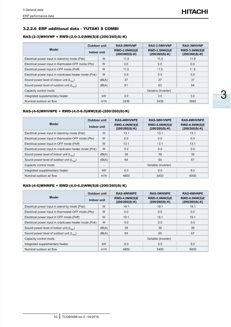
8/16/2019 Hitachi Yutaki Series 2016 Αντλίες θερμότητας
http://slidepdf.com/reader/full/hitachi-yutaki-series-2016- 63/256
3 General data
ERP performance data
TCGB0098 rev.0 - 04/201653
3
3.2.2.6 ERP additional data - YUTAKI S COMBI
RAS-(2-3)WHVNP + RWD-(2.0-3.0)NW(S)E-(200/260)S(-K)
Model
Outdoor unit RAS-2WHVNP RAS-2.5WHVNP RAS-3WHVNP
Indoor unitRWD-2.0NW(S)E
(200/260)S(-K)
RWD-2.5NW(S)E
(200/260)S(-K)
RWD-3.0NW(S)E
(200/260)S(-K)
Electrical power input in stand-by mode (Psb) W 11.9 11.9 11.9
Electrical power input in thermostat-OFF mode (Pto) W 0.0 0.0 0.0
Electrical power input in OFF mode (Poff) W 11.9 11.9 11.9
Electrical power input in crankcase heater mode (Pck) W 0.0 0.0 0.0
Sound power level of indoor unit (LWA
) dB(A) 37 37 37
Sound power level of outdoor unit (LWA
) dB(A) 61 63 64
Capacity control mode - Variable (Inverter)
Integrated supplementary heater kW 3.0 3.0 3.0
Nominal outdoor air ow m3/h 2436 2436 2682
RAS-(4-6)WHVNPE + RWD-(4.0-6.0)NW(S)E-(200/260)S(-K)
Model
Outdoor unit RAS-4WHVNPE RAS-5WHVNPE RAS-6WHVNPE
Indoor unitRWD-4.0NW(S)E
(200/260)S(-K)
RWD-5.0NW(S)E
(200/260)S(-K)
RWD-6.0NW(S)E
(200/260)S(-K)
Electrical power input in stand-by mode (Psb) W 13.1 13.1 13.1
Electrical power input in thermostat-OFF mode (Pto) W 0.0 0.0 0.0
Electrical power input in OFF mode (Poff) W 13.1 13.1 13.1
Electrical power input in crankcase heater mode (Pck) W 0.0 0.0 0.0
Sound power level of indoor unit (LWA
) dB(A) 39 39 39
Sound power level of outdoor unit (LWA
) dB(A) 64 65 67
Capacity control mode - Variable (Inverter)
Integrated supplementary heater kW 6.0 6.0 6.0Nominal outdoor air ow m3/h 4800 5400 6000
RAS-(4-6)WHNPE + RWD-(4.0-6.0)NW(S)E-(200/260)S(-K)
Model
Outdoor unit RAS-4WHNPE RAS-5WHNPE RAS-6WHNPE
Indoor unitRWD-4.0NW(S)E
(200/260)S(-K)
RWD-5.0NW(S)E
(200/260)S(-K)
RWD-6.0NW(S)E
(200/260)S(-K)
Electrical power input in stand-by mode (Psb) W 19.1 19.1 19.1
Electrical power input in thermostat-OFF mode (Pto) W 0.0 0.0 0.0
Electrical power input in OFF mode (Poff) W 19.1 19.1 19.1
Electrical power input in crankcase heater mode (Pck) W 0.0 0.0 0.0
Sound power level of indoor unit (LWA) dB(A) 39 39 39Sound power level of outdoor unit (L
WA) dB(A) 64 65 67
Capacity control mode - Variable (Inverter)
Integrated supplementary heater kW 6.0 6.0 6.0
Nominal outdoor air ow m3/h 4800 5400 6000
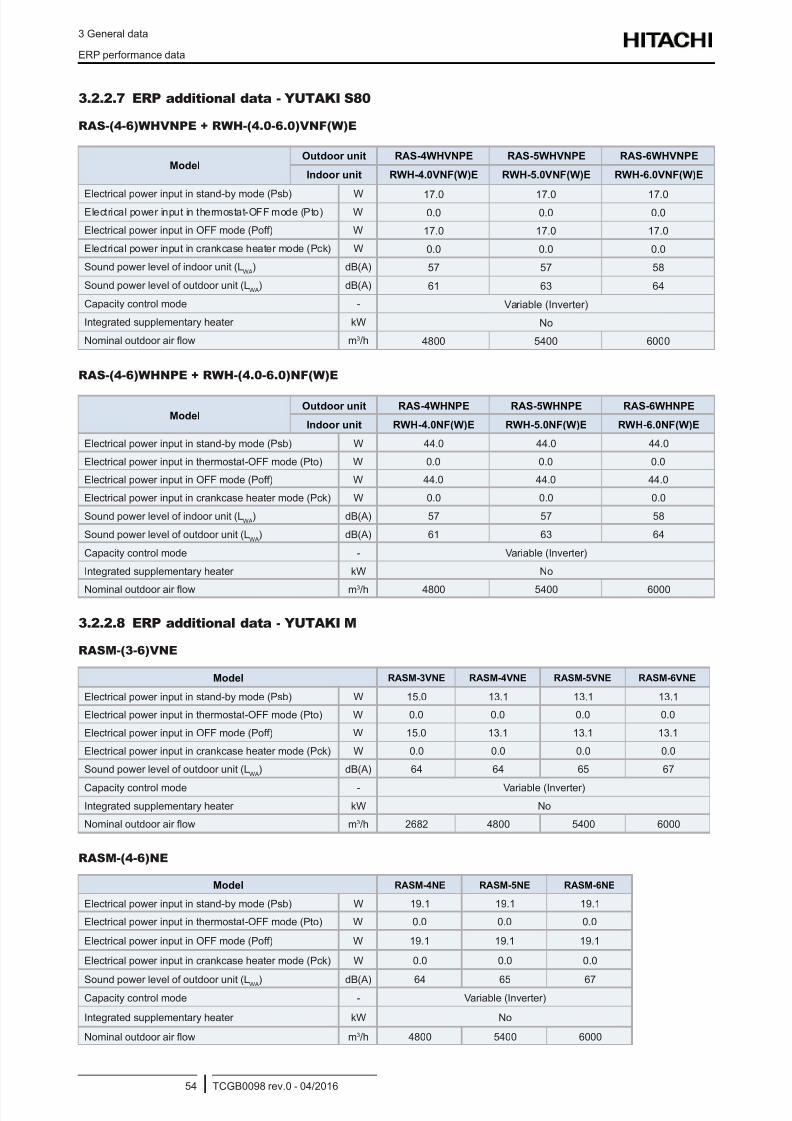
8/16/2019 Hitachi Yutaki Series 2016 Αντλίες θερμότητας
http://slidepdf.com/reader/full/hitachi-yutaki-series-2016- 64/256
3 General data
ERP performance data
TCGB0098 rev.0 - 04/201654
3.2.2.7 ERP additional data - YUTAKI S80
RAS-(4-6)WHVNPE + RWH-(4.0-6.0)VNF(W)E
ModelOutdoor unit RAS-4WHVNPE RAS-5WHVNPE RAS-6WHVNPE
Indoor unit RWH-4.0VNF(W)E RWH-5.0VNF(W)E RWH-6.0VNF(W)E
Electrical power input in stand-by mode (Psb) W 17.0 17.0 17.0Electrical power input in thermostat-OFF mode (Pto) W 0.0 0.0 0.0
Electrical power input in OFF mode (Poff) W 17.0 17.0 17.0
Electrical power input in crankcase heater mode (Pck) W 0.0 0.0 0.0
Sound power level of indoor unit (LWA
) dB(A) 57 57 58
Sound power level of outdoor unit (LWA
) dB(A) 61 63 64
Capacity control mode - Variable (Inverter)
Integrated supplementary heater kW No
Nominal outdoor air ow m3/h 4800 5400 6000
RAS-(4-6)WHNPE + RWH-(4.0-6.0)NF(W)E
ModelOutdoor unit RAS-4WHNPE RAS-5WHNPE RAS-6WHNPE
Indoor unit RWH-4.0NF(W)E RWH-5.0NF(W)E RWH-6.0NF(W)E
Electrical power input in stand-by mode (Psb) W 44.0 44.0 44.0
Electrical power input in thermostat-OFF mode (Pto) W 0.0 0.0 0.0
Electrical power input in OFF mode (Poff) W 44.0 44.0 44.0
Electrical power input in crankcase heater mode (Pck) W 0.0 0.0 0.0
Sound power level of indoor unit (LWA
) dB(A) 57 57 58
Sound power level of outdoor unit (LWA
) dB(A) 61 63 64
Capacity control mode - Variable (Inverter)
Integrated supplementary heater kW No
Nominal outdoor air ow m3/h 4800 5400 6000
3.2.2.8 ERP additional data - YUTAKI M
RASM-(3-6)VNE
Model RASM-3VNE RASM-4VNE RASM-5VNE RASM-6VNE
Electrical power input in stand-by mode (Psb) W 15.0 13.1 13.1 13.1
Electrical power input in thermostat-OFF mode (Pto) W 0.0 0.0 0.0 0.0
Electrical power input in OFF mode (Poff) W 15.0 13.1 13.1 13.1
Electrical power input in crankcase heater mode (Pck) W 0.0 0.0 0.0 0.0
Sound power level of outdoor unit (LWA
) dB(A) 64 64 65 67
Capacity control mode - Variable (Inverter)
Integrated supplementary heater kW No
Nominal outdoor air ow m3/h 2682 4800 5400 6000
RASM-(4-6)NE
Model RASM-4NE RASM-5NE RASM-6NE
Electrical power input in stand-by mode (Psb) W 19.1 19.1 19.1
Electrical power input in thermostat-OFF mode (Pto) W 0.0 0.0 0.0
Electrical power input in OFF mode (Poff) W 19.1 19.1 19.1
Electrical power input in crankcase heater mode (Pck) W 0.0 0.0 0.0
Sound power level of outdoor unit (LWA) dB(A) 64 65 67Capacity control mode - Variable (Inverter)
Integrated supplementary heater kW No
Nominal outdoor air ow m3/h 4800 5400 6000
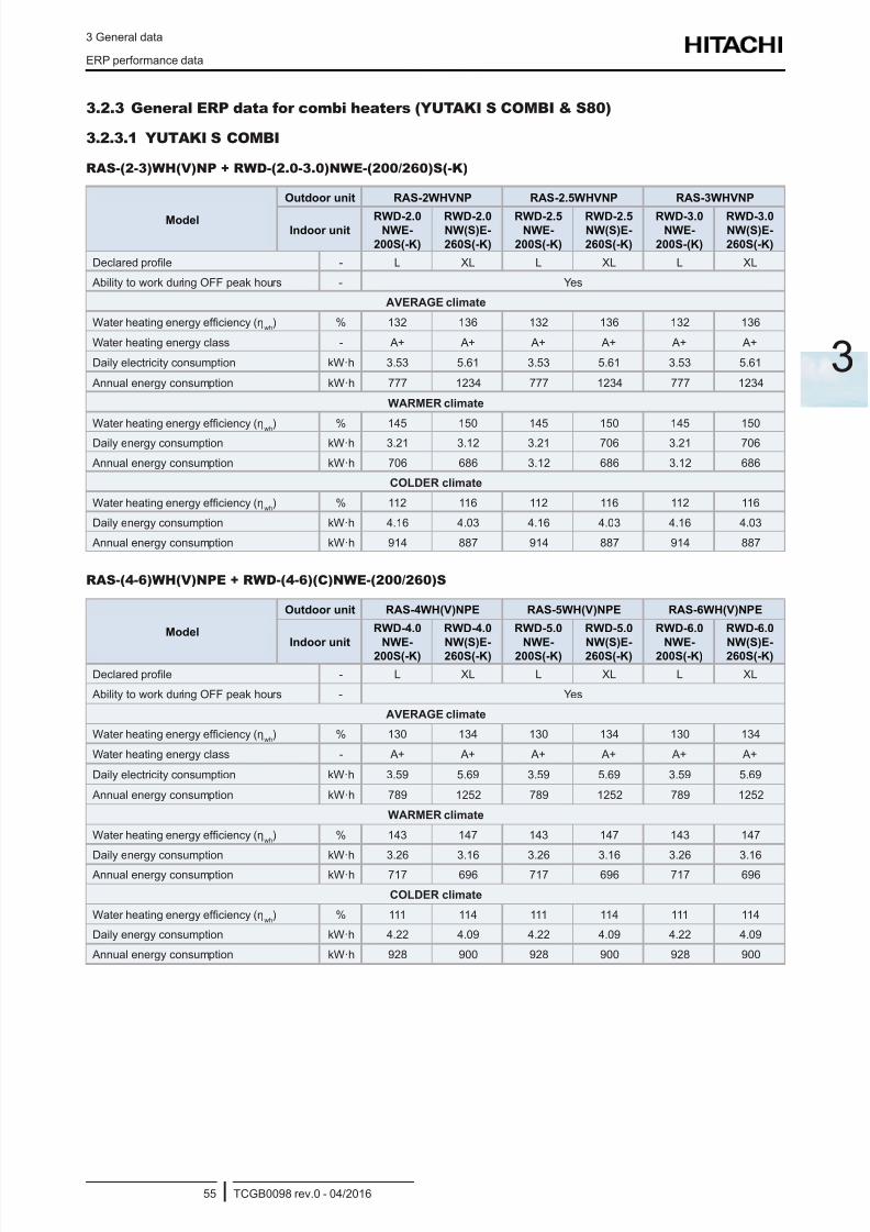
8/16/2019 Hitachi Yutaki Series 2016 Αντλίες θερμότητας
http://slidepdf.com/reader/full/hitachi-yutaki-series-2016- 65/256
3 General data
ERP performance data
TCGB0098 rev.0 - 04/201655
3
3.2.3 General ERP data for combi heaters (YUTAKI S COMBI & S80)
3.2.3.1 YUTAKI S COMBI
RAS-(2-3)WH(V)NP + RWD-(2.0-3.0)NWE-(200/260)S(-K)
Model
Outdoor unit RAS-2WHVNP RAS-2.5WHVNP RAS-3WHVNP
Indoor unitRWD-2.0
NWE-
200S(-K)
RWD-2.0NW(S)E-
260S(-K)
RWD-2.5NWE-
200S(-K)
RWD-2.5NW(S)E-
260S(-K)
RWD-3.0NWE-
200S-(K)
RWD-3.0NW(S)E-
260S(-K)
Declared prole - L XL L XL L XL
Ability to work during OFF peak hours - Yes
AVERAGE climate
Water heating energy efciency (ηwh
) % 132 136 132 136 132 136
Water heating energy class - A+ A+ A+ A+ A+ A+
Daily electricity consumption kW·h 3.53 5.61 3.53 5.61 3.53 5.61
Annual energy consumption kW·h 777 1234 777 1234 777 1234
WARMER climate
Water heating energy efciency (ηwh
) % 145 150 145 150 145 150
Daily energy consumption kW·h 3.21 3.12 3.21 706 3.21 706
Annual energy consumption kW·h 706 686 3.12 686 3.12 686
COLDER climate
Water heating energy efciency (ηwh
) % 112 116 112 116 112 116
Daily energy consumption kW·h 4.16 4.03 4.16 4.03 4.16 4.03
Annual energy consumption kW·h 914 887 914 887 914 887
RAS-(4-6)WH(V)NPE + RWD-(4-6)(C)NWE-(200/260)S
Model
Outdoor unit RAS-4WH(V)NPE RAS-5WH(V)NPE RAS-6WH(V)NPE
Indoor unit
RWD-4.0
NWE-200S(-K)
RWD-4.0
NW(S)E-260S(-K)
RWD-5.0
NWE-200S(-K)
RWD-5.0
NW(S)E-260S(-K)
RWD-6.0
NWE-200S(-K)
RWD-6.0
NW(S)E-260S(-K)
Declared prole - L XL L XL L XL
Ability to work during OFF peak hours - Yes
AVERAGE climate
Water heating energy efciency (ηwh
) % 130 134 130 134 130 134
Water heating energy class - A+ A+ A+ A+ A+ A+
Daily electricity consumption kW·h 3.59 5.69 3.59 5.69 3.59 5.69
Annual energy consumption kW·h 789 1252 789 1252 789 1252
WARMER climate
Water heating energy efciency (ηwh
) % 143 147 143 147 143 147
Daily energy consumption kW·h 3.26 3.16 3.26 3.16 3.26 3.16
Annual energy consumption kW·h 717 696 717 696 717 696
COLDER climate
Water heating energy efciency (ηwh
) % 111 114 111 114 111 114
Daily energy consumption kW·h 4.22 4.09 4.22 4.09 4.22 4.09
Annual energy consumption kW·h 928 900 928 900 928 900
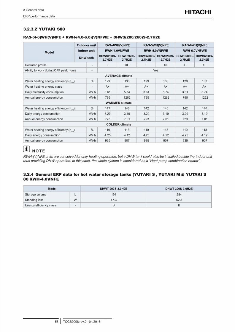
8/16/2019 Hitachi Yutaki Series 2016 Αντλίες θερμότητας
http://slidepdf.com/reader/full/hitachi-yutaki-series-2016- 66/256
3 General data
ERP performance data
TCGB0098 rev.0 - 04/201656
3.2.3.2 YUTAKI S80
RAS-(4-6)WH(V)NPE + RWH-(4.0-6.0)(V)NFWE + DHWS(200/260)S-2.7H2E
Model
Outdoor unit RAS-4WH(V)NPE RAS-5WH(V)NPE RAS-6WH(V)NPE
Indoor unit RWH-4.0VNFWE RWH-5.0VNFWE RWH-6.0VNFWE
DHW tankDHWS200S-
2.7H2E
DHWS260S-
2.7H2E
DHWS200S-
2.7H2E
DHWS260S-
2.7H2E
DHWS200S-
2.7H2E
DHWS260S-
2.7H2E
Declared prole - L XL L XL L XL
Ability to work during OFF peak hours - Yes
AVERAGE climate
Water heating energy efciency (ηwh
) % 129 133 129 133 129 133
Water heating energy class - A+ A+ A+ A+ A+ A+
Daily electricity consumption kW·h 3.61 5.74 3.61 5.74 3.61 5.74
Annual energy consumption kW·h 795 1262 795 1262 795 1262
WARMER climate
Water heating energy efciency (ηwh
) % 142 146 142 146 142 146
Daily energy consumption kW·h 3.29 3.19 3.29 3.19 3.29 3.19
Annual energy consumption kW·h 723 7.01 723 7.01 723 7.01
COLDER climate
Water heating energy efciency (ηwh
) % 110 113 110 113 110 113
Daily energy consumption kW·h 4.25 4.12 4.25 4.12 4.25 4.12
Annual energy consumption kW·h 935 907 935 907 935 907
N O T E
RWH-(V)NFE units are conceived for only heating operation, but a DHW tank could also be installed beside the indoor unit
thus providing DHW operation. In this case, the whole system is considered as a “Heat pump combination heater”.
3.2.4 General ERP data for hot water storage tanks (YUTAKI S , YUTAKI M & YUTAKI S80 RWH-4.0VNFE
Model DHWT-200S-3.0H2E DHWT-300S-3.0H2E
Storage volume L 194 284
Standing loss W 47.3 62.8
Energy efciency class - B B
8/16/2019 Hitachi Yutaki Series 2016 Αντλίες θερμότητας
http://slidepdf.com/reader/full/hitachi-yutaki-series-2016- 67/256
3 General data
General specications
TCGB0098 rev.0 - 04/201657
3
3.3 General specifcations
3.3.1 Considerations
• The sound data is based on the following conditions:
- Outdoor ambient temperature (DB/WB): 7/6ºC.
- Water inlet/outlet temperature: 47/55ºC (mark: *1); 30/35ºC (mark: *2). - Distance of the unit from the measuring point: At 1 meter from the unit’s front surface; 1,5 meter from oor level.
- The sound pressure level is measured in an anechoic chamber, so reected sound should be taken into consid-
eration when installing the unit.
- The sound power level is measured in a reverberant room, in accordance with the standard EN12102. Used envi-
ronment conditions are the same that specied in EN14511 for performance test.
• The nominal water ow rate is calculated under the following conditions:
- Outdoor ambient temperature (DB/WB): 7/6ºC.
- Water inlet/outlet temperature: 47/55ºC (mark: *1); 30/35ºC (mark: *2).
• Regarding data market with mark: *3, it corresponds to the height of the unit with the minimum mounting foot height.
This value can be adjusted up to +30 mm.
• For specic details about data corresponding to the working range, please refer to the chapter “6. Working range” .
Keywords:
• DB: Dry bulb
• WB: Wet bulb
•
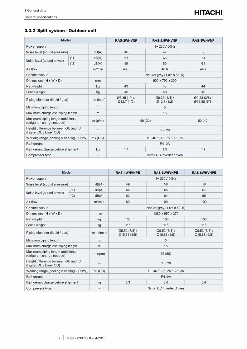
8/16/2019 Hitachi Yutaki Series 2016 Αντλίες θερμότητας
http://slidepdf.com/reader/full/hitachi-yutaki-series-2016- 68/256
3 General data
General specications
TCGB0098 rev.0 - 04/201658
3.3.2 Split system - Outdoor unit
Model RAS-2WHVNP RAS-2.5WHVNP RAS-3WHVNP
Power supply - 1~ 230V 50Hz
Noise level (sound pressure) dB(A) 46 47 50
Noise level (sound power)
(*1) dB(A) 61 63 64
(*2) dB(A) 59 60 61
Air ow m3/min 40.6 40.6 44.7
Cabinet colour - Natural grey (1.0Y 8.5/0.5)
Dimensions (H x W x D) mm 600 x 792 x 300
Net weight kg 43 43 44
Gross weight kg 48 48 49
Piping diameter (liquid / gas) mm (inch)Ø6.35 (1/4) /Ø12.7 (1/2)
Ø6.35 (1/4) /Ø12.7 (1/2)
Ø9.52 (3/8) /Ø15.88 (5/8)
Minimum piping length m 5
Maximum chargeless piping length m 15
Maximum piping length (additional
refrigerant charge needed) m (g/m) 50 (30) 50 (40)
Height difference between OU and IU
(higher OU / lower OU)m 30 / 20
Working range (cooling // heating // DHW) ºC (DB) 10~46 // -15~25 / -15~35
Refrigerant - R410A
Refrigerant charge before shipment kg 1.4 1.5 1.7
Compressor type - Scroll DC Inverter driven
Model RAS-4WHVNPE RAS-5WHVNPE RAS-6WHVNPE
Power supply - 1~ 230V 50Hz
Noise level (sound pressure) dB(A) 49 50 50
Noise level (sound power)(*1) dB(A) 64 65 67
(*2) dB(A) 63 64 65
Air ow m3/min 80 90 100
Cabinet colour - Natural grey (1.0Y 8.5/0.5)
Dimensions (H x W x D) mm 1380 x 950 x 370
Net weight kg 103 103 103
Gross weight kg 116 116 116
Piping diameter (liquid / gas) mm (inch)Ø9.52 (3/8) /
Ø15.88 (5/8)
Ø9.52 (3/8) /
Ø15.88 (5/8)
Ø9.52 (3/8) /
Ø15.88 (5/8)
Minimum piping length m 5
Maximum chargeless piping length m 15
Maximum piping length (additional
refrigerant charge needed)m (g/m) 75 (60)
Height difference between OU and IU(higher OU / lower OU)
m 30 / 20
Working range (cooling // heating // DHW) ºC (DB) 10~46 // -25~25 / -25~35
Refrigerant - R410A
Refrigerant charge before shipment kg 3.3 3.4 3.4
Compressor type - Scroll DC Inverter driven
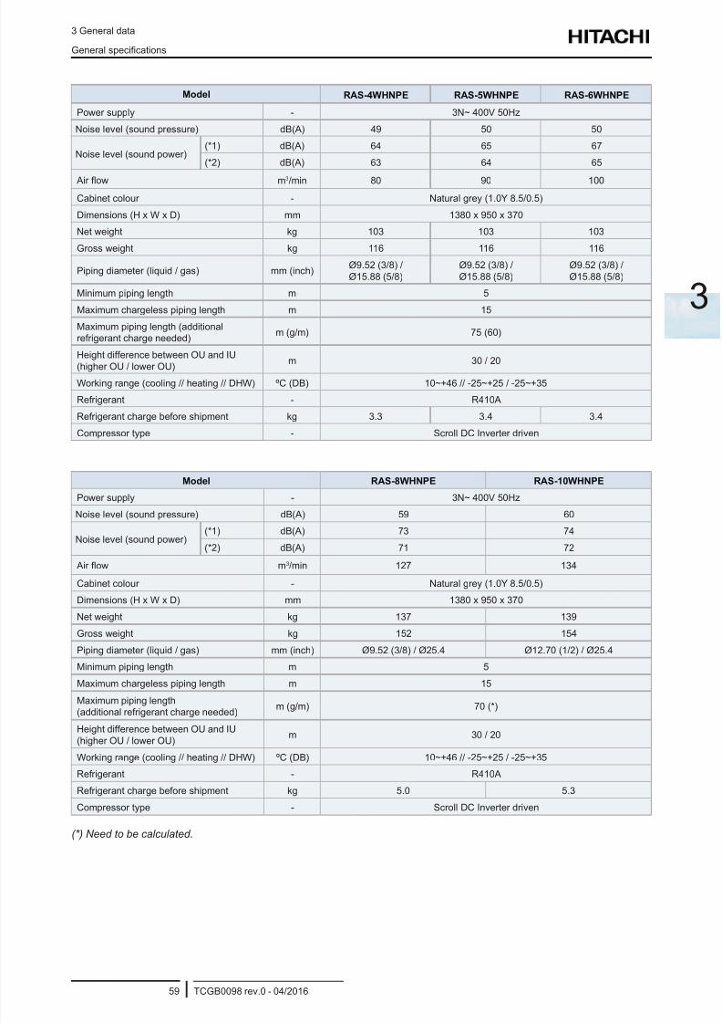
8/16/2019 Hitachi Yutaki Series 2016 Αντλίες θερμότητας
http://slidepdf.com/reader/full/hitachi-yutaki-series-2016- 69/256
3 General data
General specications
TCGB0098 rev.0 - 04/201659
3
Model RAS-4WHNPE RAS-5WHNPE RAS-6WHNPE
Power supply - 3N~ 400V 50Hz
Noise level (sound pressure) dB(A) 49 50 50
Noise level (sound power)(*1) dB(A) 64 65 67
(*2) dB(A) 63 64 65
Air ow m3/min 80 90 100
Cabinet colour - Natural grey (1.0Y 8.5/0.5)
Dimensions (H x W x D) mm 1380 x 950 x 370
Net weight kg 103 103 103
Gross weight kg 116 116 116
Piping diameter (liquid / gas) mm (inch)Ø9.52 (3/8) /
Ø15.88 (5/8)
Ø9.52 (3/8) /
Ø15.88 (5/8)
Ø9.52 (3/8) /
Ø15.88 (5/8)
Minimum piping length m 5
Maximum chargeless piping length m 15
Maximum piping length (additionalrefrigerant charge needed)
m (g/m) 75 (60)
Height difference between OU and IU(higher OU / lower OU) m 30 / 20
Working range (cooling // heating // DHW) ºC (DB) 10~+46 // -25~+25 / -25~+35
Refrigerant - R410A
Refrigerant charge before shipment kg 3.3 3.4 3.4
Compressor type - Scroll DC Inverter driven
Model RAS-8WHNPE RAS-10WHNPE
Power supply - 3N~ 400V 50Hz
Noise level (sound pressure) dB(A) 59 60
Noise level (sound power)(*1) dB(A) 73 74
(*2) dB(A) 71 72
Air ow m3/min 127 134
Cabinet colour - Natural grey (1.0Y 8.5/0.5)
Dimensions (H x W x D) mm 1380 x 950 x 370
Net weight kg 137 139
Gross weight kg 152 154
Piping diameter (liquid / gas) mm (inch) Ø9.52 (3/8) / Ø25.4 Ø12.70 (1/2) / Ø25.4
Minimum piping length m 5
Maximum chargeless piping length m 15
Maximum piping length
(additional refrigerant charge needed)
m (g/m) 70 (*)
Height difference between OU and IU
(higher OU / lower OU)m 30 / 20
Working range (cooling // heating // DHW) ºC (DB) 10~+46 // -25~+25 / -25~+35
Refrigerant - R410A
Refrigerant charge before shipment kg 5.0 5.3
Compressor type - Scroll DC Inverter driven
(*) Need to be calculated.
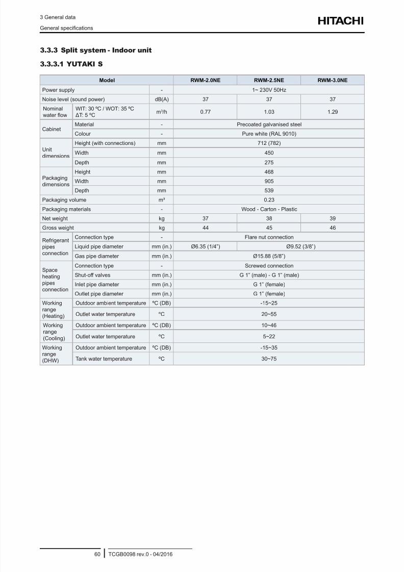
8/16/2019 Hitachi Yutaki Series 2016 Αντλίες θερμότητας
http://slidepdf.com/reader/full/hitachi-yutaki-series-2016- 70/256
3 General data
General specications
TCGB0098 rev.0 - 04/201660
3.3.3 Split system - Indoor unit
3.3.3.1 YUTAKI S
Model RWM-2.0NE RWM-2.5NE RWM-3.0NE
Power supply - 1~ 230V 50Hz
Noise level (sound power) dB(A) 37 37 37Nominalwater ow
WIT: 30 ºC / WOT: 35 ºC ΔT: 5 ºC
m3/h 0.77 1.03 1.29
CabinetMaterial - Precoated galvanised steel
Colour - Pure white (RAL 9010)
Unit
dimensions
Height (with connections) mm 712 (782)
Width mm 450
Depth mm 275
Packaging
dimensions
Height mm 468
Width mm 905
Depth mm 539
Packaging volume m³ 0.23
Packaging materials - Wood - Carton - Plastic
Net weight kg 37 38 39
Gross weight kg 44 45 46
Refrigerantpipes
connection
Connection type - Flare nut connection
Liquid pipe diameter mm (in.) Ø6.35 (1/4”) Ø9.52 (3/8”)
Gas pipe diameter mm (in.) Ø15.88 (5/8”)
Space
heating
pipes
connection
Connection type - Screwed connection
Shut-off valves mm (in.) G 1” (male) - G 1” (male)
Inlet pipe diameter mm (in.) G 1” (female)
Outlet pipe diameter mm (in.) G 1” (female)
Working
range
(Heating)
Outdoor ambient temperature ºC (DB) -15~25
Outlet water temperature ºC 20~55
Working
range
(Cooling)
Outdoor ambient temperature ºC (DB) 10~46
Outlet water temperature ºC 5~22
Workingrange
(DHW)
Outdoor ambient temperature ºC (DB) -15~35
Tank water temperature ºC 30~75
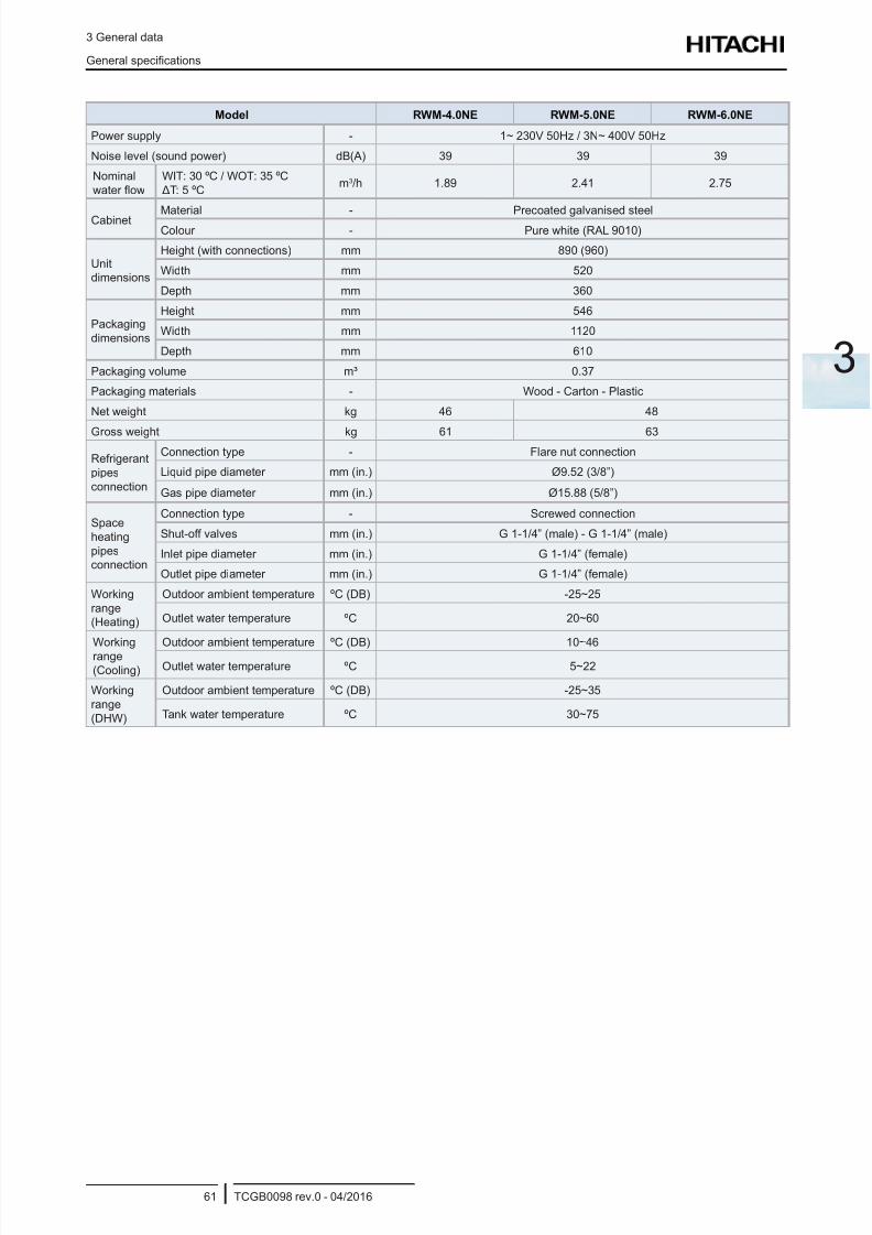
8/16/2019 Hitachi Yutaki Series 2016 Αντλίες θερμότητας
http://slidepdf.com/reader/full/hitachi-yutaki-series-2016- 71/256
3 General data
General specications
TCGB0098 rev.0 - 04/201661
3
Model RWM-4.0NE RWM-5.0NE RWM-6.0NE
Power supply - 1~ 230V 50Hz / 3N~ 400V 50Hz
Noise level (sound power) dB(A) 39 39 39
Nominal
water ow
WIT: 30 ºC / WOT: 35 ºC
ΔT: 5 ºCm3/h 1.89 2.41 2.75
Cabinet Material - Precoated galvanised steelColour - Pure white (RAL 9010)
Unitdimensions
Height (with connections) mm 890 (960)
Width mm 520
Depth mm 360
Packaging
dimensions
Height mm 546
Width mm 1120
Depth mm 610
Packaging volume m³ 0.37
Packaging materials - Wood - Carton - Plastic
Net weight kg 46 48
Gross weight kg 61 63
Refrigerant
pipes
connection
Connection type - Flare nut connection
Liquid pipe diameter mm (in.) Ø9.52 (3/8”)
Gas pipe diameter mm (in.) Ø15.88 (5/8”)
Space
heating
pipesconnection
Connection type - Screwed connection
Shut-off valves mm (in.) G 1-1/4” (male) - G 1-1/4” (male)
Inlet pipe diameter mm (in.) G 1-1/4” (female)
Outlet pipe diameter mm (in.) G 1-1/4” (female)
Working
range(Heating)
Outdoor ambient temperature ºC (DB) -25~25
Outlet water temperature ºC 20~60
Working
range
(Cooling)
Outdoor ambient temperature ºC (DB) 10~46
Outlet water temperature ºC 5~22
Working
range
(DHW)
Outdoor ambient temperature ºC (DB) -25~35
Tank water temperature ºC 30~75
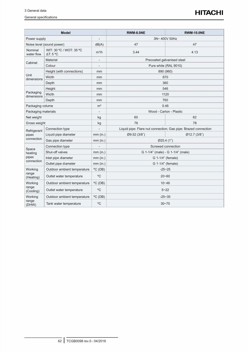
8/16/2019 Hitachi Yutaki Series 2016 Αντλίες θερμότητας
http://slidepdf.com/reader/full/hitachi-yutaki-series-2016- 72/256
3 General data
General specications
TCGB0098 rev.0 - 04/201662
Model RWM-8.0NE RWM-10.0NE
Power supply - 3N~ 400V 50Hz
Noise level (sound power) dB(A) 47 47
Nominal
water ow
WIT: 30 ºC / WOT: 35 ºC
ΔT: 5 ºCm3/h 3.44 4.13
Cabinet Material - Precoated galvanised steelColour - Pure white (RAL 9010)
Unitdimensions
Height (with connections) mm 890 (960)
Width mm 670
Depth mm 360
Packaging
dimensions
Height mm 546
Width mm 1120
Depth mm 760
Packaging volume m³ 0.46
Packaging materials - Wood - Carton - Plastic
Net weight kg 60 62
Gross weight kg 76 78
Refrigerant
pipes
connection
Connection type - Liquid pipe: Flare nut connection; Gas pipe: Brazed connection
Liquid pipe diameter mm (in.) Ø9.52 (3/8”) Ø12.7 (3/8”)
Gas pipe diameter mm (in.) Ø25.4 (1”)
Space
heating
pipesconnection
Connection type - Screwed connection
Shut-off valves mm (in.) G 1-1/4” (male) - G 1-1/4” (male)
Inlet pipe diameter mm (in.) G 1-1/4” (female)
Outlet pipe diameter mm (in.) G 1-1/4” (female)
Working
range(Heating)
Outdoor ambient temperature ºC (DB) -25~25
Outlet water temperature ºC 20~60
Working
range
(Cooling)
Outdoor ambient temperature ºC (DB) 10~46
Outlet water temperature ºC 5~22
Working
range
(DHW)
Outdoor ambient temperature ºC (DB) -25~35
Tank water temperature ºC 30~75
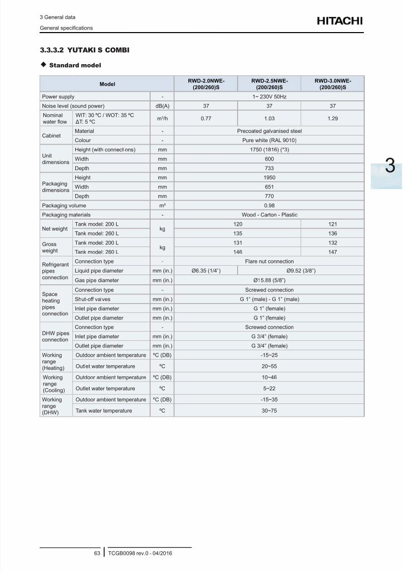
8/16/2019 Hitachi Yutaki Series 2016 Αντλίες θερμότητας
http://slidepdf.com/reader/full/hitachi-yutaki-series-2016- 73/256
3 General data
General specications
TCGB0098 rev.0 - 04/201663
3
3.3.3.2 YUTAKI S COMBI
Standard model
ModelRWD-2.0NWE-
(200/260)S
RWD-2.5NWE-
(200/260)S
RWD-3.0NWE-
(200/260)S
Power supply - 1~ 230V 50Hz
Noise level (sound power) dB(A) 37 37 37
Nominal
water ow
WIT: 30 ºC / WOT: 35 ºC
ΔT: 5 ºCm3/h 0.77 1.03 1.29
CabinetMaterial - Precoated galvanised steel
Colour - Pure white (RAL 9010)
Unitdimensions
Height (with connections) mm 1750 (1816) (*3)
Width mm 600
Depth mm 733
Packaging
dimensions
Height mm 1950
Width mm 651
Depth mm 770
Packaging volume m³ 0.98
Packaging materials - Wood - Carton - Plastic
Net weightTank model: 200 L
kg120 121
Tank model: 260 L 135 136
Grossweight
Tank model: 200 Lkg
131 132
Tank model: 260 L 146 147
Refrigerantpipes
connection
Connection type - Flare nut connection
Liquid pipe diameter mm (in.) Ø6.35 (1/4”) Ø9.52 (3/8”)
Gas pipe diameter mm (in.) Ø15.88 (5/8”)
Space
heatingpipes
connection
Connection type - Screwed connection
Shut-off valves mm (in.) G 1” (male) - G 1” (male)Inlet pipe diameter mm (in.) G 1” (female)
Outlet pipe diameter mm (in.) G 1” (female)
DHW pipesconnection
Connection type - Screwed connection
Inlet pipe diameter mm (in.) G 3/4” (female)
Outlet pipe diameter mm (in.) G 3/4” (female)
Workingrange
(Heating)
Outdoor ambient temperature ºC (DB) -15~25
Outlet water temperature ºC 20~55
Working
range(Cooling)
Outdoor ambient temperature ºC (DB) 10~46
Outlet water temperature ºC 5~22
Workingrange(DHW)
Outdoor ambient temperature ºC (DB) -15~35
Tank water temperature ºC 30~75

8/16/2019 Hitachi Yutaki Series 2016 Αντλίες θερμότητας
http://slidepdf.com/reader/full/hitachi-yutaki-series-2016- 74/256
3 General data
General specications
TCGB0098 rev.0 - 04/201664
ModelRWD-4.0NWE-
(200/260)S
RWD-5.0NWE-
(200/260)S
RWD-6.0NWE-
(200/260)S
Power supply - 1~ 230V 50Hz / 3N~ 400V 50Hz
Noise level (sound power) dB(A) 39 39 39
Nominalwater ow
WIT: 30 ºC / WOT: 35 ºC ΔT: 5 ºC
m3/h 1.89 2.41 2.75
CabinetMaterial - Precoated galvanised steel
Colour - Pure white (RAL 9010)
Unit
dimensions
Height (with connections) mm 1750 (1816) (*3)
Width mm 600
Depth mm 733
Packaging
dimensions
Height mm 1950
Width mm 651
Depth mm 770
Packaging volume m³ 0.98
Packaging materials - Wood - Carton - Plastic
Net weightTank model: 200 L
kg124 126
Tank model: 260 L 139 141
Gross
weight
Tank model: 200 Lkg
135 137
Tank model: 260 L 150 152
Refrigerant
pipesconnection
Connection type - Flare nut connection
Liquid pipe diameter mm (in.) Ø9.52 (3/8”)
Gas pipe diameter mm (in.) Ø15.88 (5/8”)
Spaceheating
pipes
connection
Connection type - Screwed connection
Shut-off valves mm (in.) G 1-1/4” (male) - G 1-1/4” (male)
Inlet pipe diameter mm (in.) G 1-1/4” (female)
Outlet pipe diameter mm (in.) G 1-1/4” (female)
DHW pipes
connection
Connection type - Screwed connectionInlet pipe diameter mm (in.) G 3/4” (female)
Outlet pipe diameter mm (in.) G 3/4” (female)
Working
range(Heating)
Outdoor ambient temperature ºC (DB) -25~25
Outlet water temperature ºC 20~60
Working
range
(Cooling)
Outdoor ambient temperature ºC (DB) 10~46
Outlet water temperature ºC 5~22
Working
range
(DHW)
Outdoor ambient temperature ºC (DB) -25~35
Tank water temperature ºC 30~75
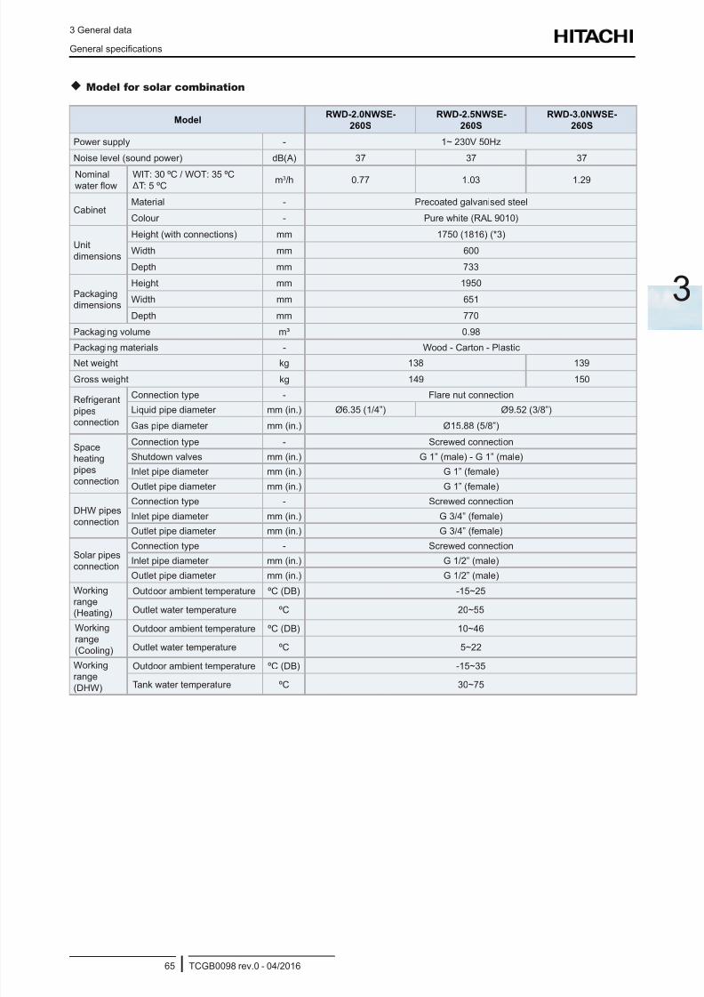
8/16/2019 Hitachi Yutaki Series 2016 Αντλίες θερμότητας
http://slidepdf.com/reader/full/hitachi-yutaki-series-2016- 75/256
3 General data
General specications
TCGB0098 rev.0 - 04/201665
3
Model for solar combination
ModelRWD-2.0NWSE-
260S
RWD-2.5NWSE-
260S
RWD-3.0NWSE-
260S
Power supply - 1~ 230V 50Hz
Noise level (sound power) dB(A) 37 37 37
Nominalwater ow
WIT: 30 ºC / WOT: 35 ºC ΔT: 5 ºC
m3/h 0.77 1.03 1.29
CabinetMaterial - Precoated galvanised steel
Colour - Pure white (RAL 9010)
Unit
dimensions
Height (with connections) mm 1750 (1816) (*3)
Width mm 600
Depth mm 733
Packagingdimensions
Height mm 1950
Width mm 651
Depth mm 770
Packaging volume m³ 0.98
Packaging materials - Wood - Carton - PlasticNet weight kg 138 139
Gross weight kg 149 150
Refrigerant
pipesconnection
Connection type - Flare nut connection
Liquid pipe diameter mm (in.) Ø6.35 (1/4”) Ø9.52 (3/8”)
Gas pipe diameter mm (in.) Ø15.88 (5/8”)
Spaceheating
pipes
connection
Connection type - Screwed connection
Shutdown valves mm (in.) G 1” (male) - G 1” (male)
Inlet pipe diameter mm (in.) G 1” (female)
Outlet pipe diameter mm (in.) G 1” (female)
DHW pipes
connection
Connection type - Screwed connection
Inlet pipe diameter mm (in.) G 3/4” (female)
Outlet pipe diameter mm (in.) G 3/4” (female)
Solar pipes
connection
Connection type - Screwed connection
Inlet pipe diameter mm (in.) G 1/2” (male)
Outlet pipe diameter mm (in.) G 1/2” (male)
Working
range(Heating)
Outdoor ambient temperature ºC (DB) -15~25
Outlet water temperature ºC 20~55
Working
range
(Cooling)
Outdoor ambient temperature ºC (DB) 10~46
Outlet water temperature ºC 5~22
Working
range
(DHW)
Outdoor ambient temperature ºC (DB) -15~35
Tank water temperature ºC 30~75
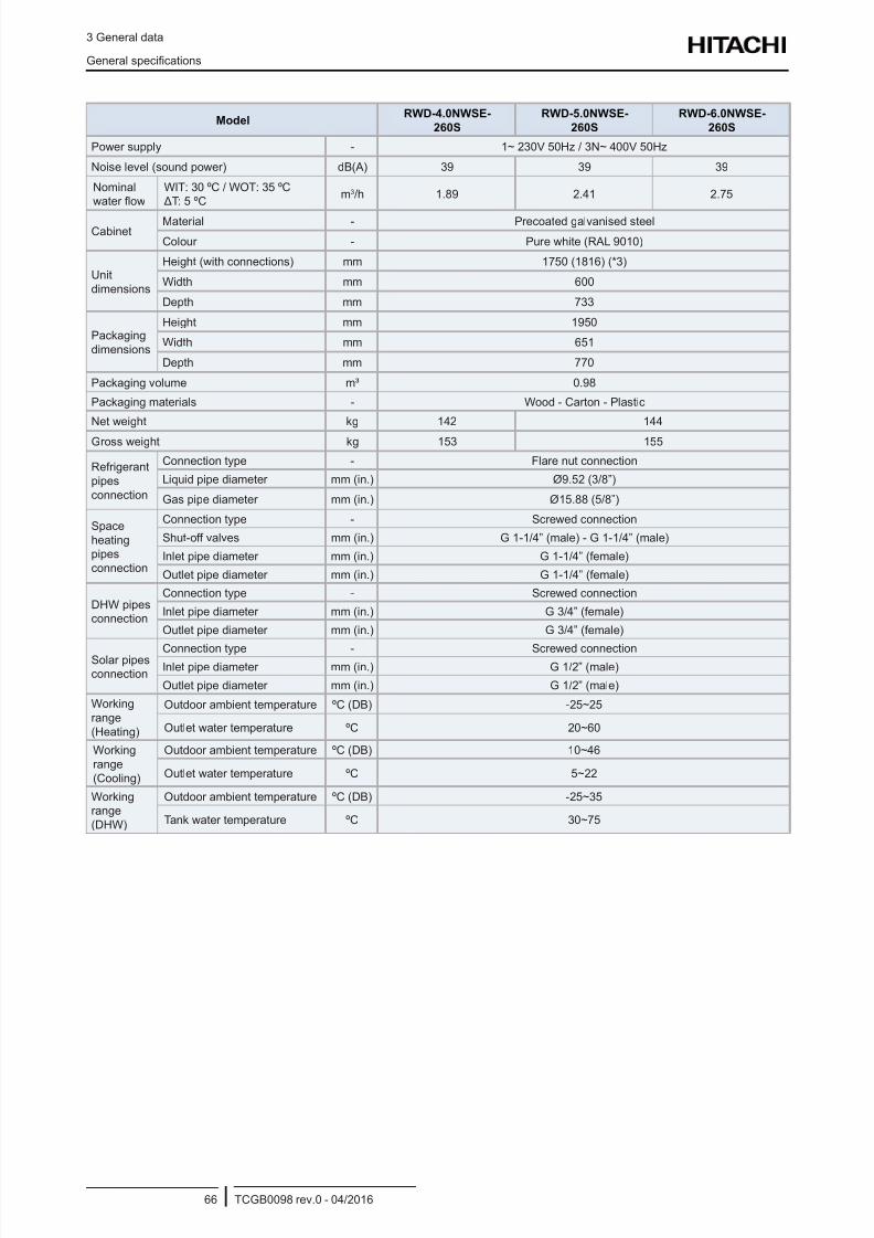
8/16/2019 Hitachi Yutaki Series 2016 Αντλίες θερμότητας
http://slidepdf.com/reader/full/hitachi-yutaki-series-2016- 76/256
3 General data
General specications
TCGB0098 rev.0 - 04/201666
ModelRWD-4.0NWSE-
260S
RWD-5.0NWSE-
260S
RWD-6.0NWSE-
260S
Power supply - 1~ 230V 50Hz / 3N~ 400V 50Hz
Noise level (sound power) dB(A) 39 39 39
Nominalwater ow
WIT: 30 ºC / WOT: 35 ºC ΔT: 5 ºC
m3/h 1.89 2.41 2.75
CabinetMaterial - Precoated galvanised steel
Colour - Pure white (RAL 9010)
Unit
dimensions
Height (with connections) mm 1750 (1816) (*3)
Width mm 600
Depth mm 733
Packaging
dimensions
Height mm 1950
Width mm 651
Depth mm 770
Packaging volume m³ 0.98
Packaging materials - Wood - Carton - Plastic
Net weight kg 142 144
Gross weight kg 153 155
Refrigerant
pipes
connection
Connection type - Flare nut connection
Liquid pipe diameter mm (in.) Ø9.52 (3/8”)
Gas pipe diameter mm (in.) Ø15.88 (5/8”)
Space
heatingpipes
connection
Connection type - Screwed connection
Shut-off valves mm (in.) G 1-1/4” (male) - G 1-1/4” (male)
Inlet pipe diameter mm (in.) G 1-1/4” (female)
Outlet pipe diameter mm (in.) G 1-1/4” (female)
DHW pipesconnection
Connection type - Screwed connection
Inlet pipe diameter mm (in.) G 3/4” (female)
Outlet pipe diameter mm (in.) G 3/4” (female)
Solar pipesconnection
Connection type - Screwed connectionInlet pipe diameter mm (in.) G 1/2” (male)
Outlet pipe diameter mm (in.) G 1/2” (male)
Working
range
(Heating)
Outdoor ambient temperature ºC (DB) -25~25
Outlet water temperature ºC 20~60
Working
range
(Cooling)
Outdoor ambient temperature ºC (DB) 10~46
Outlet water temperature ºC 5~22
Workingrange
(DHW)
Outdoor ambient temperature ºC (DB) -25~35
Tank water temperature ºC 30~75
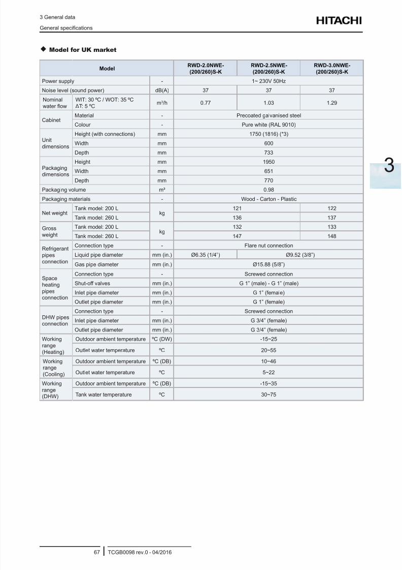
8/16/2019 Hitachi Yutaki Series 2016 Αντλίες θερμότητας
http://slidepdf.com/reader/full/hitachi-yutaki-series-2016- 77/256
3 General data
General specications
TCGB0098 rev.0 - 04/201667
3
Model for UK market
ModelRWD-2.0NWE-
(200/260)S-K
RWD-2.5NWE-
(200/260)S-K
RWD-3.0NWE-
(200/260)S-K
Power supply - 1~ 230V 50Hz
Noise level (sound power) dB(A) 37 37 37
Nominalwater ow
WIT: 30 ºC / WOT: 35 ºC ΔT: 5 ºC
m3/h 0.77 1.03 1.29
CabinetMaterial - Precoated galvanised steel
Colour - Pure white (RAL 9010)
Unit
dimensions
Height (with connections) mm 1750 (1816) (*3)
Width mm 600
Depth mm 733
Packagingdimensions
Height mm 1950
Width mm 651
Depth mm 770
Packaging volume m³ 0.98
Packaging materials - Wood - Carton - Plastic
Net weightTank model: 200 L
kg121 122
Tank model: 260 L 136 137
Gross
weight
Tank model: 200 Lkg
132 133
Tank model: 260 L 147 148
Refrigerant
pipes
connection
Connection type - Flare nut connection
Liquid pipe diameter mm (in.) Ø6.35 (1/4”) Ø9.52 (3/8”)
Gas pipe diameter mm (in.) Ø15.88 (5/8”)
Space
heating
pipes
connection
Connection type - Screwed connection
Shut-off valves mm (in.) G 1” (male) - G 1” (male)
Inlet pipe diameter mm (in.) G 1” (female)
Outlet pipe diameter mm (in.) G 1” (female)
DHW pipesconnection
Connection type - Screwed connection
Inlet pipe diameter mm (in.) G 3/4” (female)
Outlet pipe diameter mm (in.) G 3/4” (female)
Working
range
(Heating)
Outdoor ambient temperature ºC (DW) -15~25
Outlet water temperature ºC 20~55
Workingrange
(Cooling)
Outdoor ambient temperature ºC (DB) 10~46
Outlet water temperature ºC 5~22
Working
range(DHW)
Outdoor ambient temperature ºC (DB) -15~35
Tank water temperature ºC 30~75
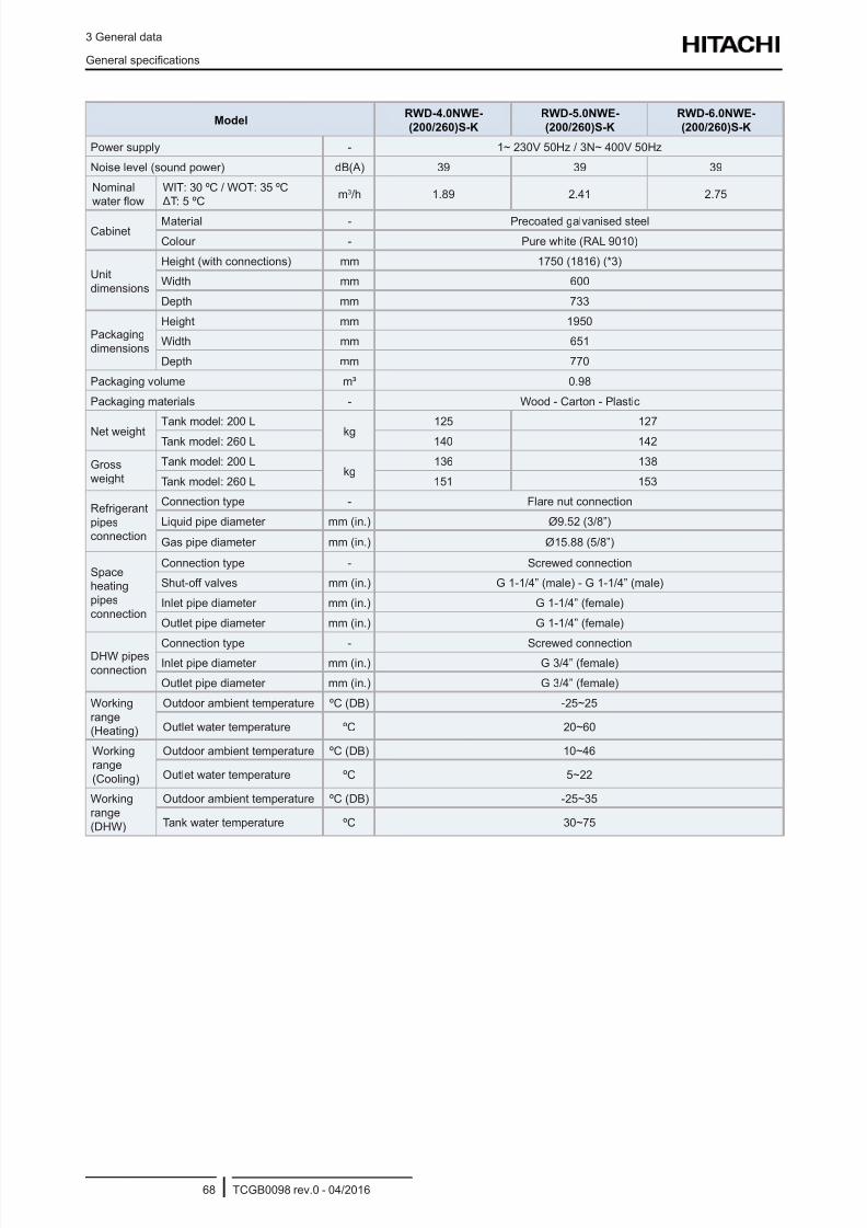
8/16/2019 Hitachi Yutaki Series 2016 Αντλίες θερμότητας
http://slidepdf.com/reader/full/hitachi-yutaki-series-2016- 78/256
3 General data
General specications
TCGB0098 rev.0 - 04/201668
ModelRWD-4.0NWE-
(200/260)S-K
RWD-5.0NWE-
(200/260)S-K
RWD-6.0NWE-
(200/260)S-K
Power supply - 1~ 230V 50Hz / 3N~ 400V 50Hz
Noise level (sound power) dB(A) 39 39 39
Nominalwater ow
WIT: 30 ºC / WOT: 35 ºC ΔT: 5 ºC
m3/h 1.89 2.41 2.75
CabinetMaterial - Precoated galvanised steel
Colour - Pure white (RAL 9010)
Unit
dimensions
Height (with connections) mm 1750 (1816) (*3)
Width mm 600
Depth mm 733
Packaging
dimensions
Height mm 1950
Width mm 651
Depth mm 770
Packaging volume m³ 0.98
Packaging materials - Wood - Carton - Plastic
Net weightTank model: 200 L
kg125 127
Tank model: 260 L 140 142
Gross
weight
Tank model: 200 Lkg
136 138
Tank model: 260 L 151 153
Refrigerant
pipesconnection
Connection type - Flare nut connection
Liquid pipe diameter mm (in.) Ø9.52 (3/8”)
Gas pipe diameter mm (in.) Ø15.88 (5/8”)
Spaceheating
pipes
connection
Connection type - Screwed connection
Shut-off valves mm (in.) G 1-1/4” (male) - G 1-1/4” (male)
Inlet pipe diameter mm (in.) G 1-1/4” (female)
Outlet pipe diameter mm (in.) G 1-1/4” (female)
DHW pipes
connection
Connection type - Screwed connectionInlet pipe diameter mm (in.) G 3/4” (female)
Outlet pipe diameter mm (in.) G 3/4” (female)
Working
range(Heating)
Outdoor ambient temperature ºC (DB) -25~25
Outlet water temperature ºC 20~60
Working
range
(Cooling)
Outdoor ambient temperature ºC (DB) 10~46
Outlet water temperature ºC 5~22
Working
range
(DHW)
Outdoor ambient temperature ºC (DB) -25~35
Tank water temperature ºC 30~75
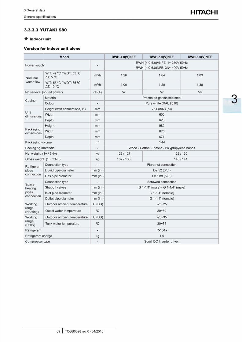
8/16/2019 Hitachi Yutaki Series 2016 Αντλίες θερμότητας
http://slidepdf.com/reader/full/hitachi-yutaki-series-2016- 79/256
3 General data
General specications
TCGB0098 rev.0 - 04/201669
3
3.3.3.3 YUTAKI S80
Indoor unit
Version for indoor unit alone
Model RWH-4.0(V)NFE RWH-5.0(V)NFE RWH-6.0(V)NFE
Power supply -RWH-(4.0-6.0)VNFE: 1~ 230V 50Hz
RWH-(4.0-6.0)NFE: 3N~ 400V 50Hz
Nominalwater ow
WIT: 47 ºC / WOT: 55 ºC ΔT: 5 ºC
m3/h 1.26 1.64 1.83
WIT: 55 ºC / WOT: 65 ºC
ΔT: 10 ºCm3/h 1.00 1.20 1.38
Noise level (sound power) dB(A) 57 57 58
CabinetMaterial - Precoated galvanised steel
Colour - Pure white (RAL 9010)
Unit
dimensions
Height (with connections) (*) mm 751 (802) (*3)
Width mm 600
Depth mm 623
Packagingdimensions
Height mm 982
Width mm 675
Depth mm 671
Packaging volume m³ 0.44
Packaging materials - Wood - Carton - Plastic - Polypropylene bands
Net weight (1~ / 3N~) kg 126 / 127 129 / 130
Gross weight (1~ / 3N~) kg 137 / 138 140 / 141
Refrigerant
pipesconnection
Connection type - Flare nut connection
Liquid pipe diameter mm (in.) Ø9.52 (3/8”)
Gas pipe diameter mm (in.) Ø15.88 (5/8”)
Spaceheating
pipes
connection
Connection type - Screwed connection
Shut-off valves mm (in.) G 1-1/4” (male) - G 1-1/4” (male)
Inlet pipe diameter mm (in.) G 1-1/4” (female)
Outlet pipe diameter mm (in.) G 1-1/4” (female)
Workingrange
(Heating)
Outdoor ambient temperature ºC (DB) -25~25
Outlet water temperature ºC 20~80
Working
range
(DHW)
Outdoor ambient temperature ºC (DB) -25~35
Tank water temperature ºC 30~75
Refrigerant - R-134a
Refrigerant charge kg 1.9
Compressor type - Scroll DC Inverter driven
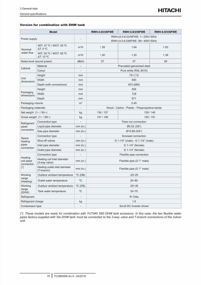
8/16/2019 Hitachi Yutaki Series 2016 Αντλίες θερμότητας
http://slidepdf.com/reader/full/hitachi-yutaki-series-2016- 80/256
3 General data
General specications
TCGB0098 rev.0 - 04/201670
Version for combination with DHW tank
Model RWH-4.0(V)NFWE RWH-5.0(V)NFWE RWH-6.0(V)NFWE
Power supply -RWH-(4.0-6.0)VNFWE: 1~ 230V 50Hz
RWH-(4.0-6.0)NFWE: 3N~ 400V 50Hz
Nominalwater ow
WIT: 47 ºC / WOT: 55 ºC
ΔT: 5 ºC
m3/h 1.26 1.64 1.83
WIT: 55 ºC / WOT: 65 ºC
ΔT: 10 ºCm3/h 1.00 1.20 1.38
Noise level (sound power) dB(A) 57 57 58
CabinetMaterial - Precoated galvanised steel
Colour - Pure white (RAL 9010)
Unit
dimensions
Height mm 751 (*3)
Width mm 600
Depth (with connections) mm 623 (680)
Packagingdimensions
Height mm 926
Width mm 728
Depth mm 671Packaging volume m³ 0.45
Packaging materials - Wood - Carton - Plastic - Polypropylene bands
Net weight (1~ / 3N~) kg 136 / 137 139 / 140
Gross weight (1~ / 3N~) kg 147 / 148 150 / 151
Refrigerant
pipesconnection
Connection type - Flare nut connection
Liquid pipe diameter mm (in.) Ø9.52 (3/8”)
Gas pipe diameter mm (in.) Ø15.88 (5/8”)
Space
heatingpipes
connection
Connection type - Screwed connection
Shut-off valves mm (in.) G 1-1/4” (male) - G 1-1/4” (male)
Inlet pipe diameter mm (in.) G 1-1/4” (female)
Outlet pipe diameter mm (in.) G 1-1/4” (female)
Heating
coil pipes
connection(*)
Connection type - Flexible pipe connection
Heating coil inlet diameter
(3-way valve)mm (in.) Flexible pipe (G 1” male)
Heating outlet inlet diameter
(T-branch)mm (in.) Flexible pipe (G 1” male)
Working
range
(Heating)
Outdoor ambient temperature ºC (DB) -25~25
Outlet water temperature ºC 20~80
Working
range
(DHW)
Outdoor ambient temperature ºC (DB) -25~35
Tank water temperature ºC 30~75
Refrigerant - R-134a
Refrigerant charge kg 1.9
Compressor type - Scroll DC Inverter driven
(*): These models are ready for combination with YUTAKI S80 DHW tank accessory. In this case, the two exible water
pipes factory-supplied with the DHW tank must be connected to the 3-way valve and T-branch connections of the indoor
unit.
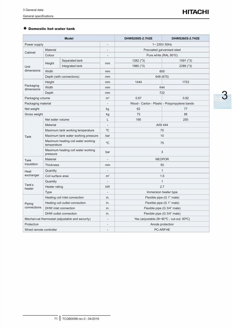
8/16/2019 Hitachi Yutaki Series 2016 Αντλίες θερμότητας
http://slidepdf.com/reader/full/hitachi-yutaki-series-2016- 81/256
3 General data
General specications
TCGB0098 rev.0 - 04/201671
3
Domestic hot water tank
Model DHWS200S-2.7H2E DHWS260S-2.7H2E
Power supply - 1~ 230V 50Hz
CabinetMaterial - Precoated galvanised steel
Colour - Pure white (RAL 9010)
Unit
dimensions
HeightSeparated tank
mm1282 (*3) 1591 (*3)
Integrated tank 1980 (*3) 2289 (*3)
Width mm 600
Depth (with connections) mm 648 (675)
Packagingdimensions
Height mm 1444 1753
Width mm 644
Depth mm 722
Packaging volume m3 0.67 0.82
Packaging material - Wood - Carton - Plastic - Polypropylene bands
Net weight kg 62 77
Gross weight kg 72 88
Tank
Net water volume L 190 250
Material - AISI 444
Maximum tank working temperature ºC 75
Maximum tank water working pressure bar 10
Maximum heating coil water working
temperatureºC 75
Maximum heating coil water working
pressurebar 3
Tank
insulation
Material - NEOPOR
Thickness mm 50
Heatexchanger
Quantity - 1
Coil surface area m2 1.6
Tank’s
heater
Quantity - 1
Heater rating kW 2.7
Type - Immersion heater type
Pipingconnections
Heating coil inlet connection in. Flexible pipe (G 1” male)
Heating coil outlet connection in. Flexible pipe (G 1” male)
DHW inlet connection in. Flexible pipe (G 3/4” male)
DHW outlet connection in. Flexible pipe (G 3/4” male)
Mechanical thermostat (adjustable and security) - Yes (adjustable 28~80ºC ; cut-out: 90ºC)
Protection - Anode protection
Wired remote controller - PC-ARFHE
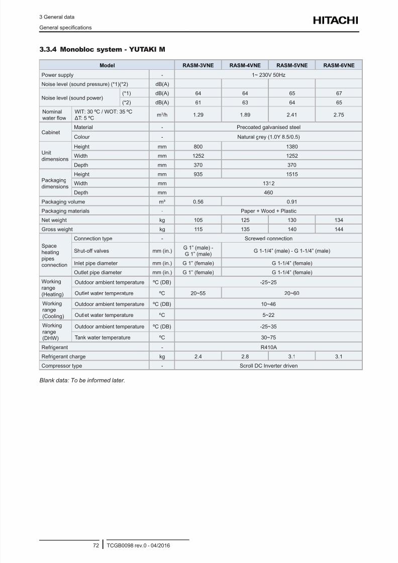
8/16/2019 Hitachi Yutaki Series 2016 Αντλίες θερμότητας
http://slidepdf.com/reader/full/hitachi-yutaki-series-2016- 82/256
3 General data
General specications
TCGB0098 rev.0 - 04/201672
3.3.4 Monobloc system - YUTAKI M
Model RASM-3VNE RASM-4VNE RASM-5VNE RASM-6VNE
Power supply - 1~ 230V 50Hz
Noise level (sound pressure) (*1)(*2) dB(A)
Noise level (sound power)
(*1) dB(A) 64 64 65 67
(*2) dB(A) 61 63 64 65
Nominalwater ow
WIT: 30 ºC / WOT: 35 ºC ΔT: 5 ºC
m3/h 1.29 1.89 2.41 2.75
CabinetMaterial - Precoated galvanised steel
Colour - Natural grey (1.0Y 8.5/0.5)
Unit
dimensions
Height mm 800 1380
Width mm 1252 1252
Depth mm 370 370
Packaging
dimensions
Height mm 935 1515
Width mm 1312
Depth mm 460
Packaging volume m³ 0.56 0.91
Packaging materials - Paper + Wood + Plastic
Net weight kg 105 125 130 134
Gross weight kg 115 135 140 144
Space
heating
pipesconnection
Connection type - Screwed connection
Shut-off valves mm (in.)G 1” (male) -G 1” (male)
G 1-1/4” (male) - G 1-1/4” (male)
Inlet pipe diameter mm (in.) G 1” (female) G 1-1/4” (female)
Outlet pipe diameter mm (in.) G 1” (female) G 1-1/4” (female)
Working
range
(Heating)
Outdoor ambient temperature ºC (DB) -25~25
Outlet water temperature ºC 20~55 20~60Workingrange
(Cooling)
Outdoor ambient temperature ºC (DB) 10~46
Outlet water temperature ºC 5~22
Working
range(DHW)
Outdoor ambient temperature ºC (DB) -25~35
Tank water temperature ºC 30~75
Refrigerant - R410A
Refrigerant charge kg 2.4 2.8 3.1 3.1
Compressor type - Scroll DC Inverter driven
Blank data: To be informed later.
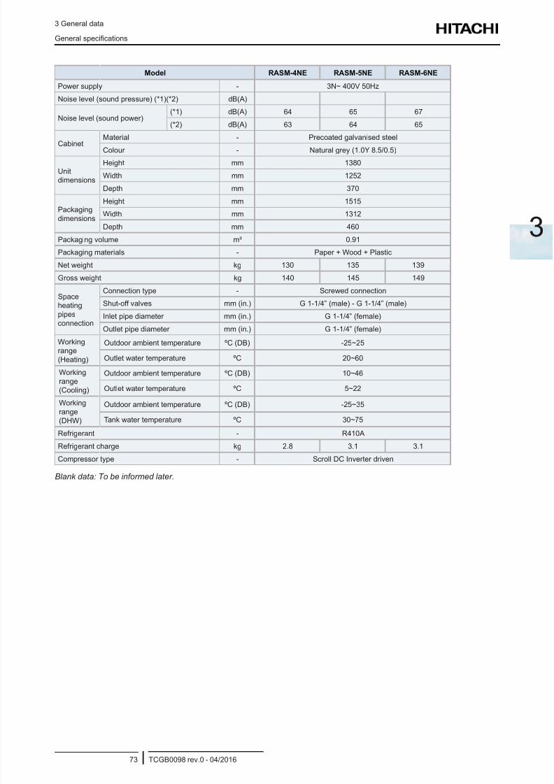
8/16/2019 Hitachi Yutaki Series 2016 Αντλίες θερμότητας
http://slidepdf.com/reader/full/hitachi-yutaki-series-2016- 83/256
3 General data
General specications
TCGB0098 rev.0 - 04/201673
3
Model RASM-4NE RASM-5NE RASM-6NE
Power supply - 3N~ 400V 50Hz
Noise level (sound pressure) (*1)(*2) dB(A)
Noise level (sound power)(*1) dB(A) 64 65 67
(*2) dB(A) 63 64 65
Cabinet Material - Precoated galvanised steel
Colour - Natural grey (1.0Y 8.5/0.5)
Unitdimensions
Height mm 1380
Width mm 1252
Depth mm 370
Packaging
dimensions
Height mm 1515
Width mm 1312
Depth mm 460
Packaging volume m³ 0.91
Packaging materials - Paper + Wood + Plastic
Net weight kg 130 135 139
Gross weight kg 140 145 149
Spaceheating
pipes
connection
Connection type - Screwed connection
Shut-off valves mm (in.) G 1-1/4” (male) - G 1-1/4” (male)
Inlet pipe diameter mm (in.) G 1-1/4” (female)
Outlet pipe diameter mm (in.) G 1-1/4” (female)
Workingrange
(Heating)
Outdoor ambient temperature ºC (DB) -25~25
Outlet water temperature ºC 20~60
Working
range(Cooling)
Outdoor ambient temperature ºC (DB) 10~46
Outlet water temperature ºC 5~22
Working
range(DHW)
Outdoor ambient temperature ºC (DB) -25~35
Tank water temperature ºC 30~75
Refrigerant - R410A
Refrigerant charge kg 2.8 3.1 3.1
Compressor type - Scroll DC Inverter driven
Blank data: To be informed later.
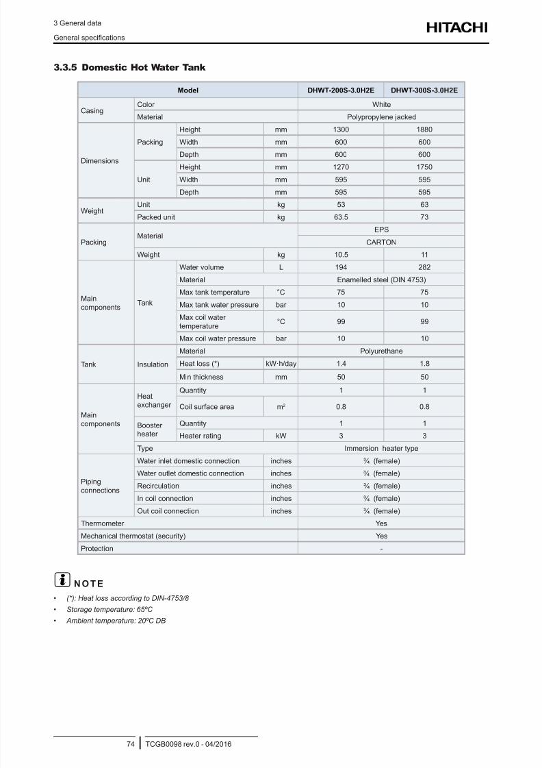
8/16/2019 Hitachi Yutaki Series 2016 Αντλίες θερμότητας
http://slidepdf.com/reader/full/hitachi-yutaki-series-2016- 84/256
3 General data
General specications
TCGB0098 rev.0 - 04/201674
3.3.5 Domestic Hot Water Tank
Model DHWT-200S-3.0H2E DHWT-300S-3.0H2E
CasingColor White
Material Polypropylene jacked
Dimensions
Packing
Height mm 1300 1880
Width mm 600 600
Depth mm 600 600
Unit
Height mm 1270 1750
Width mm 595 595
Depth mm 595 595
WeightUnit kg 53 63
Packed unit kg 63.5 73
PackingMaterial
EPS
CARTON
Weight kg 10.5 11
Main
componentsTank
Water volume L 194 282Material Enamelled steel (DIN 4753)
Max tank temperature °C 75 75
Max tank water pressure bar 10 10
Max coil water
temperature°C 99 99
Max coil water pressure bar 10 10
Tank Insulation
Material Polyurethane
Heat loss (*) kW·h/day 1.4 1.8
Min thickness mm 50 50
Main
components
Heat
exchanger
Quantity 1 1
Coil surface area m2 0.8 0.8
Boosterheater
Quantity 1 1
Heater rating kW 3 3
Type Immersion heater type
Piping
connections
Water inlet domestic connection inches ¾ (female)
Water outlet domestic connection inches ¾ (female)
Recirculation inches ¾ (female)
In coil connection inches ¾ (female)
Out coil connection inches ¾ (female)
Thermometer Yes
Mechanical thermostat (security) YesProtection -
? N O T E
• (*): Heat loss according to DIN-4753/8
• Storage temperature: 65ºC
• Ambient temperature: 20ºC DB
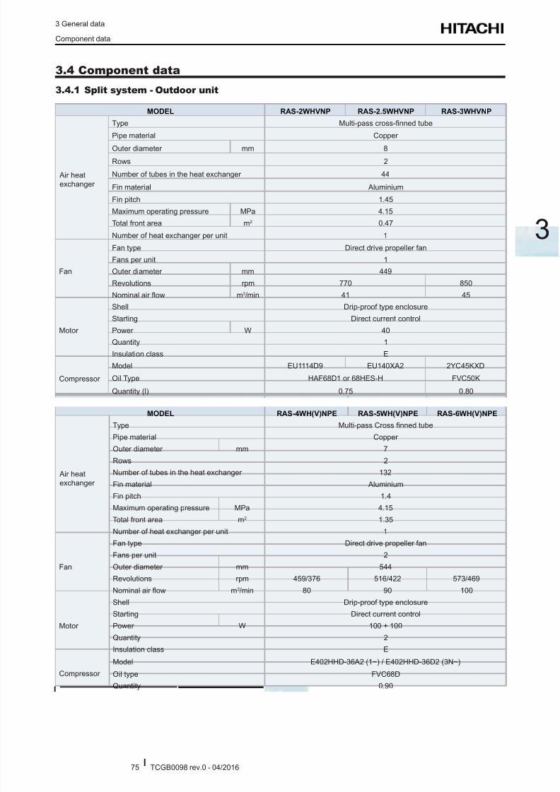
8/16/2019 Hitachi Yutaki Series 2016 Αντλίες θερμότητας
http://slidepdf.com/reader/full/hitachi-yutaki-series-2016- 85/256
3 General data
Component data
TCGB0098 rev.0 - 04/201675
3
3.4 Component data
3.4.1 Split system - Outdoor unit
MODEL RAS-2WHVNP RAS-2.5WHVNP RAS-3WHVNP
Air heat
exchanger
Type Multi-pass cross-nned tube
Pipe material Copper Outer diameter mm 8
Rows 2
Number of tubes in the heat exchanger 44
Fin material Aluminium
Fin pitch 1.45
Maximum operating pressure MPa 4.15
Total front area m2 0.47
Number of heat exchanger per unit 1
Fan
Fan type Direct drive propeller fan
Fans per unit 1
Outer diameter mm 449
Revolutions rpm 770 850
Nominal air ow m3/min 41 45
Motor
Shell Drip-proof type enclosure
Starting Direct current control
Power W 40
Quantity 1
Insulation class E
Compressor
Model EU1114D9 EU140XA2 2YC45KXD
Oil Type HAF68D1 or 68HES-H FVC50K
Quantity (l) 0.75 0.80
MODEL RAS-4WH(V)NPE RAS-5WH(V)NPE RAS-6WH(V)NPE
Air heat
exchanger
Type Multi-pass Cross nned tube
Pipe material Copper
Outer diameter mm 7
Rows 2
Number of tubes in the heat exchanger 132
Fin material Aluminium
Fin pitch 1.4
Maximum operating pressure MPa 4.15
Total front area m2 1.35
Number of heat exchanger per unit 1
Fan
Fan type Direct drive propeller fan
Fans per unit 2Outer diameter mm 544
Revolutions rpm 459/376 516/422 573/469
Nominal air ow m3/min 80 90 100
Motor
Shell Drip-proof type enclosure
Starting Direct current control
Power W 100 + 100
Quantity 2
Insulation class E
Compressor
Model E402HHD-36A2 (1~) / E402HHD-36D2 (3N~)
Oil type FVC68D
Quantity 0.90
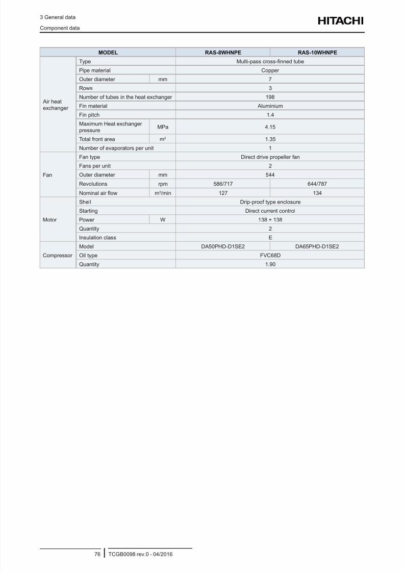
8/16/2019 Hitachi Yutaki Series 2016 Αντλίες θερμότητας
http://slidepdf.com/reader/full/hitachi-yutaki-series-2016- 86/256
3 General data
Component data
TCGB0098 rev.0 - 04/201676
MODEL RAS-8WHNPE RAS-10WHNPE
Air heatexchanger
Type Multi-pass cross-nned tube
Pipe material Copper
Outer diameter mm 7
Rows 3
Number of tubes in the heat exchanger 198
Fin material Aluminium
Fin pitch 1.4
Maximum Heat exchanger
pressureMPa 4.15
Total front area m2 1.35
Number of evaporators per unit 1
Fan
Fan type Direct drive propeller fan
Fans per unit 2
Outer diameter mm 544
Revolutions rpm 586/717 644/787
Nominal air ow m3/min 127 134
Motor
Shell Drip-proof type enclosure
Starting Direct current control
Power W 138 + 138
Quantity 2
Insulation class E
Compressor
Model DA50PHD-D1SE2 DA65PHD-D1SE2
Oil type FVC68D
Quantity 1.90
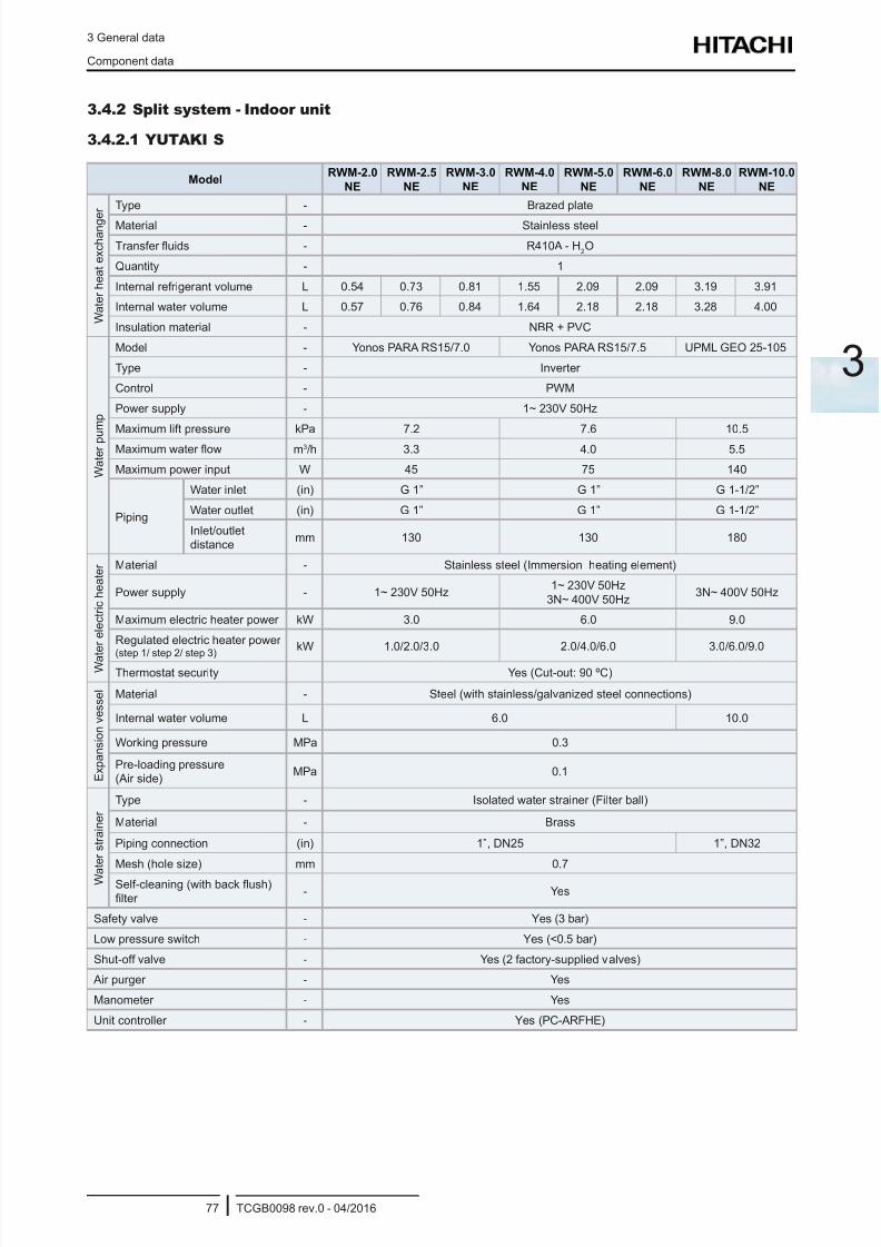
8/16/2019 Hitachi Yutaki Series 2016 Αντλίες θερμότητας
http://slidepdf.com/reader/full/hitachi-yutaki-series-2016- 87/256
3 General data
Component data
TCGB0098 rev.0 - 04/201677
3
3.4.2 Split system - Indoor unit
3.4.2.1 YUTAKI S
ModelRWM-2.0
NE
RWM-2.5
NE
RWM-3.0
NE
RWM-4.0
NE
RWM-5.0
NE
RWM-6.0
NE
RWM-8.0
NE
RWM-10.0
NE
W a t e r h e a t e x c h a n g e
r Type - Brazed plate
Material - Stainless steel
Transfer uids - R410A - H2O
Quantity - 1
Internal refrigerant volume L 0.54 0.73 0.81 1.55 2.09 2.09 3.19 3.91
Internal water volume L 0.57 0.76 0.84 1.64 2.18 2.18 3.28 4.00
Insulation material - NBR + PVC
W a t e r p u m p
Model - Yonos PARA RS15/7.0 Yonos PARA RS15/7.5 UPML GEO 25-105
Type - Inverter
Control - PWM
Power supply - 1~ 230V 50Hz
Maximum lift pressure kPa 7.2 7.6 10.5
Maximum water ow m3/h 3.3 4.0 5.5
Maximum power input W 45 75 140
Piping
Water inlet (in) G 1” G 1” G 1-1/2”
Water outlet (in) G 1” G 1” G 1-1/2”
Inlet/outletdistance
mm 130 130 180
W a t e r e l e c t r i c h e a t e r Material - Stainless steel (Immersion heating element)
Power supply - 1~ 230V 50Hz1~ 230V 50Hz
3N~ 400V 50Hz3N~ 400V 50Hz
Maximum electric heater power kW 3.0 6.0 9.0
Regulated electric heater power
(step 1/ step 2/ step 3)
kW 1.0/2.0/3.0 2.0/4.0/6.0 3.0/6.0/9.0
Thermostat security Yes (Cut-out: 90 ºC)
E x p a n s i o n v e s s e l
Material - Steel (with stainless/galvanized steel connections)
Internal water volume L 6.0 10.0
Working pressure MPa 0.3
Pre-loading pressure(Air side)
MPa 0.1
W a
t e r s t r a i n e r
Type - Isolated water strainer (Filter ball)
Material - Brass
Piping connection (in) 1”, DN25 1”, DN32
Mesh (hole size) mm 0.7
Self-cleaning (with back ush)
lter - Yes
Safety valve - Yes (3 bar)
Low pressure switch - Yes (<0.5 bar)
Shut-off valve - Yes (2 factory-supplied valves)
Air purger - Yes
Manometer - Yes
Unit controller - Yes (PC-ARFHE)
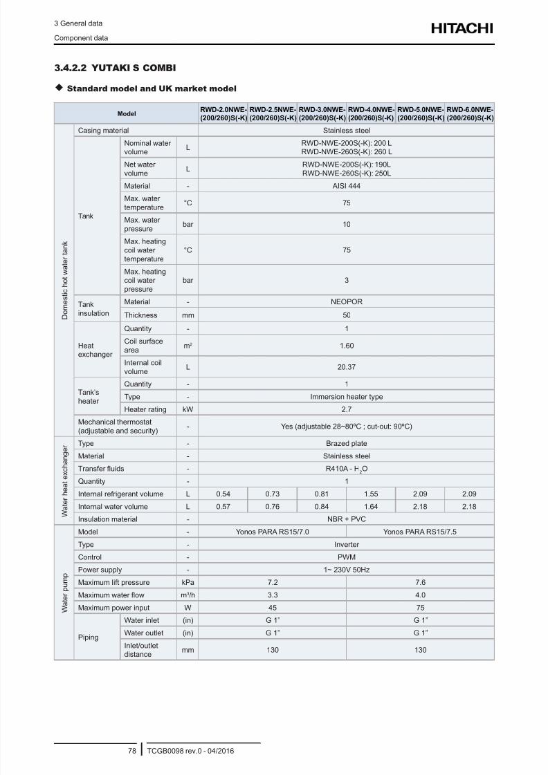
8/16/2019 Hitachi Yutaki Series 2016 Αντλίες θερμότητας
http://slidepdf.com/reader/full/hitachi-yutaki-series-2016- 88/256
3 General data
Component data
TCGB0098 rev.0 - 04/201678
3.4.2.2 YUTAKI S COMBI
Standard model and UK market model
ModelRWD-2.0NWE-
(200/260)S(-K)
RWD-2.5NWE-
(200/260)S(-K)
RWD-3.0NWE-
(200/260)S(-K)
RWD-4.0NWE-
(200/260)S(-K)
RWD-5.0NWE-
(200/260)S(-K)
RWD-6.0NWE-
(200/260)S(-K)
D o m e s t i c h o t w
a t e r t a n k
Casing material Stainless steel
Tank
Nominal watervolume
LRWD-NWE-200S(-K): 200 LRWD-NWE-260S(-K): 260 L
Net water
volumeL
RWD-NWE-200S(-K): 190L
RWD-NWE-260S(-K): 250L
Material - AISI 444
Max. water
temperature°C 75
Max. water
pressurebar 10
Max. heating
coil water
temperature
°C 75
Max. heatingcoil water
pressure
bar 3
Tank
insulation
Material - NEOPOR
Thickness mm 50
Heatexchanger
Quantity - 1
Coil surface
aream2 1.60
Internal coil
volumeL 20.37
Tank’sheater
Quantity - 1
Type - Immersion heater type
Heater rating kW 2.7
Mechanical thermostat
(adjustable and security)- Yes (adjustable 28~80ºC ; cut-out: 90ºC)
W a t e r h e a t e x c h a n g e r Type - Brazed plate
Material - Stainless steel
Transfer uids - R410A - H2O
Quantity - 1
Internal refrigerant volume L 0.54 0.73 0.81 1.55 2.09 2.09
Internal water volume L 0.57 0.76 0.84 1.64 2.18 2.18
Insulation material - NBR + PVC
W a t e r p u m p
Model - Yonos PARA RS15/7.0 Yonos PARA RS15/7.5
Type - Inverter
Control - PWM
Power supply - 1~ 230V 50Hz
Maximum lift pressure kPa 7.2 7.6
Maximum water ow m3/h 3.3 4.0
Maximum power input W 45 75
Piping
Water inlet (in) G 1” G 1”
Water outlet (in) G 1” G 1”
Inlet/outletdistance
mm 130 130
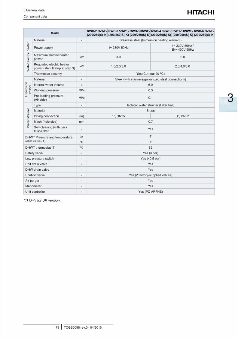
8/16/2019 Hitachi Yutaki Series 2016 Αντλίες θερμότητας
http://slidepdf.com/reader/full/hitachi-yutaki-series-2016- 89/256
3 General data
Component data
TCGB0098 rev.0 - 04/201679
3
ModelRWD-2.0NWE-
(200/260)S(-K)
RWD-2.5NWE-
(200/260)S(-K)
RWD-3.0NWE-
(200/260)S(-K)
RWD-4.0NWE-
(200/260)S(-K)
RWD-5.0NWE-
(200/260)S(-K)
RWD-6.0NWE-
(200/260)S(-K)
W a t e r e l e
c t r i c h e a t e r
Material - Stainless steel (Immersion heating element)
Power supply - 1~ 230V 50Hz1~ 230V 50Hz /
3N~ 400V 50Hz
Maximum electric heater
power kW 3.0 6.0
Regulated electric heater
power (step 1/ step 2/ step 3)kW 1.0/2.0/3.0 2.0/4.0/6.0
Thermostat security - Yes (Cut-out: 90 ºC)
E x p a n s i o n
v e s s e l
Material - Steel (with stainless/galvanized steel connections)
Internal water volume L 6.0
Working pressure MPa 0.3
Pre-loading pressure
(Air side)MPa 0.1
W a t e r s
t r a i n e r
Type - Isolated water strainer (Filter ball)
Material - Brass
Piping connection (in) 1”, DN25 1”, DN32
Mesh (hole size) mm 0.7
Self-cleaning (with backush) lter
- Yes
DHWT Pressure and temperature
relief valve (1)
bar 7
ºC 96
DHWT thermostat (1) ºC 85
Safety valve - Yes (3 bar)
Low pressure switch - Yes (<0.5 bar)
Unit drain valve - Yes
DHW drain valve - Yes
Shut-off valve - Yes (2 factory-supplied valves)
Air purger - Yes
Manometer - Yes
Unit controller - Yes (PC-ARFHE)
(1) Only for UK version.
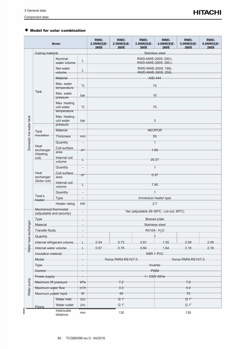
8/16/2019 Hitachi Yutaki Series 2016 Αντλίες θερμότητας
http://slidepdf.com/reader/full/hitachi-yutaki-series-2016- 90/256
3 General data
Component data
TCGB0098 rev.0 - 04/201680
Model for solar combination
Model
RWD-
2.0NW(S)E-
260S
RWD-
2.5NW(S)E-
260S
RWD-
3.0NW(S)E-
260S
RWD-
4.0NW(S)E-
260S
RWD-
5.0NW(S)E-
260S
RWD-
6.0NW(S)E-
260S
D o m e s t i c h o t w a t e r t a n k
Casing material Stainless steel
Tank
Nominalwater volume L
RWD-NWE-200S: 200 LRWD-NWE-260S: 260 L
Net water
volumeL
RWD-NWE-200S: 190L
RWD-NWE-260S: 250L
Material - AISI 444
Max. water
temperature°C 75
Max. water
pressurebar 10
Max. heating
coil water
temperature
°C 75
Max. heating
coil waterpressure bar 3
Tank
insulation
Material - NEOPOR
Thickness mm 50
Heat
exchanger(Heating
coil)
Quantity - 1
Coil surface
aream2 1.60
Internal coilvolume
L 20.37
Heat
exchanger(Solar coil)
Quantity - 1
Coil surface
aream2 0.37
Internal coilvolume
L 7.90
Tank’s
heater
Quantity - 1
Type - Immersion heater type
Heater rating kW 2.7
Mechanical thermostat
(adjustable and security)- Yes (adjustable 28~80ºC ; cut-out: 90ºC)
W a t e r
h e a t e x c h a n g e r Type - Brazed plate
Material - Stainless steel
Transfer uids - R410A - H2O
Quantity - 1
Internal refrigerant volume L 0.54 0.73 0.81 1.55 2.09 2.09
Internal water volume L 0.57 0.76 0.84 1.64 2.18 2.18
Insulation material - NBR + PVC
W a t e r p u m p
Model - Yonos PARA RS15/7.0 Yonos PARA RS15/7.5
Type - Inverter
Control - PWM
Power supply - 1~ 230V 50Hz
Maximum lift pressure kPa 7.2 7.6
Maximum water ow m3/h 3.3 4.0
Maximum power input W 45 75
Piping
Water inlet (in) G 1” G 1”
Water outlet (in) G 1” G 1”Inlet/outlet
distancemm 130 130
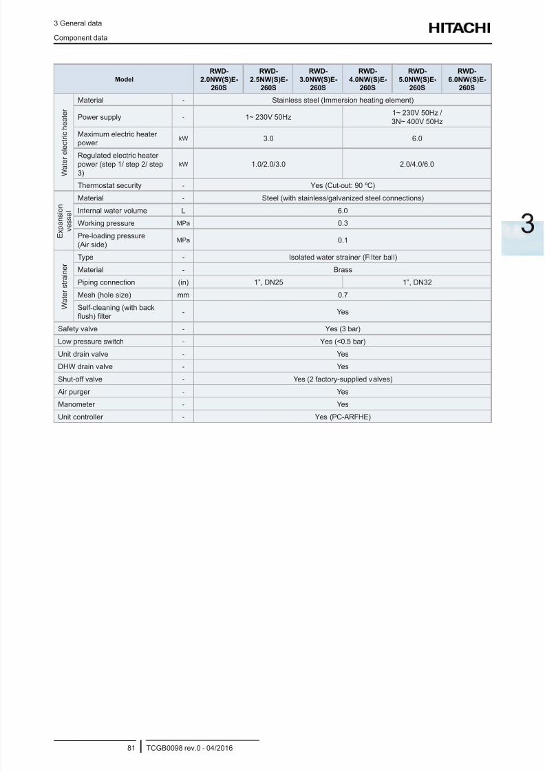
8/16/2019 Hitachi Yutaki Series 2016 Αντλίες θερμότητας
http://slidepdf.com/reader/full/hitachi-yutaki-series-2016- 91/256
3 General data
Component data
TCGB0098 rev.0 - 04/201681
3
Model
RWD-
2.0NW(S)E-
260S
RWD-
2.5NW(S)E-
260S
RWD-
3.0NW(S)E-
260S
RWD-
4.0NW(S)E-
260S
RWD-
5.0NW(S)E-
260S
RWD-
6.0NW(S)E-
260S
W a t e r e l e c t r i c
h e a t e r
Material - Stainless steel (Immersion heating element)
Power supply - 1~ 230V 50Hz1~ 230V 50Hz /
3N~ 400V 50Hz
Maximum electric heaterpower
kW 3.0 6.0
Regulated electric heater
power (step 1/ step 2/ step
3)
kW 1.0/2.0/3.0 2.0/4.0/6.0
Thermostat security - Yes (Cut-out: 90 ºC)
E x p a n s i o n
v e s s e l
Material - Steel (with stainless/galvanized steel connections)
Internal water volume L 6.0
Working pressure MPa 0.3
Pre-loading pressure
(Air side)MPa 0.1
W a t e r s t r a i n e r
Type - Isolated water strainer (Filter ball)
Material - Brass
Piping connection (in) 1”, DN25 1”, DN32
Mesh (hole size) mm 0.7
Self-cleaning (with backush) lter
- Yes
Safety valve - Yes (3 bar)
Low pressure switch - Yes (<0.5 bar)
Unit drain valve - Yes
DHW drain valve - Yes
Shut-off valve - Yes (2 factory-supplied valves)
Air purger - Yes
Manometer - YesUnit controller - Yes (PC-ARFHE)
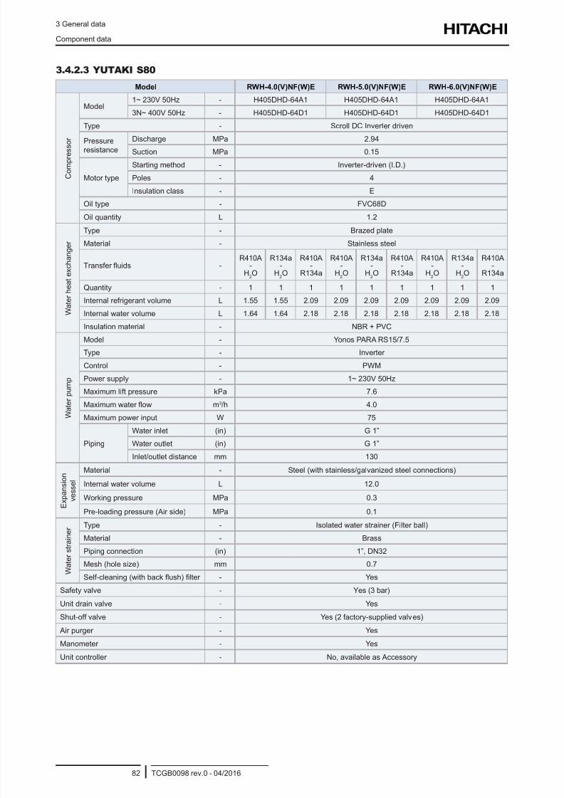
8/16/2019 Hitachi Yutaki Series 2016 Αντλίες θερμότητας
http://slidepdf.com/reader/full/hitachi-yutaki-series-2016- 92/256
3 General data
Component data
TCGB0098 rev.0 - 04/201682
3.4.2.3 YUTAKI S80
Model RWH-4.0(V)NF(W)E RWH-5.0(V)NF(W)E RWH-6.0(V)NF(W)E
C o m p r e s s o r
Model1~ 230V 50Hz - H405DHD-64A1 H405DHD-64A1 H405DHD-64A1
3N~ 400V 50Hz - H405DHD-64D1 H405DHD-64D1 H405DHD-64D1
Type - Scroll DC Inverter driven
Pressureresistance
Discharge MPa 2.94
Suction MPa 0.15
Motor type
Starting method - Inverter-driven (I.D.)
Poles - 4
Insulation class - E
Oil type - FVC68D
Oil quantity L 1.2
W a t e r h e a t
e x c h a n g e r
Type - Brazed plate
Material - Stainless steel
Transfer uids -R410A
-H
2O
R134a-
H2O
R410A-
R134a
R410A-
H2O
R134a-
H2O
R410A-
R134a
R410A-
H2O
R134a-
H2O
R410A-
R134a
Quantity - 1 1 1 1 1 1 1 1 1
Internal refrigerant volume L 1.55 1.55 2.09 2.09 2.09 2.09 2.09 2.09 2.09
Internal water volume L 1.64 1.64 2.18 2.18 2.18 2.18 2.18 2.18 2.18
Insulation material - NBR + PVC
W a t e r p u m p
Model - Yonos PARA RS15/7.5
Type - Inverter
Control - PWM
Power supply - 1~ 230V 50Hz
Maximum lift pressure kPa 7.6
Maximum water ow m3/h 4.0
Maximum power input W 75
Piping
Water inlet (in) G 1”
Water outlet (in) G 1”
Inlet/outlet distance mm 130
E x p a n s i o n
v e s s e l
Material - Steel (with stainless/galvanized steel connections)
Internal water volume L 12.0
Working pressure MPa 0.3
Pre-loading pressure (Air side) MPa 0.1
W a t e
r s t r a i n e r Type - Isolated water strainer (Filter ball)
Material - Brass
Piping connection (in) 1”, DN32
Mesh (hole size) mm 0.7
Self-cleaning (with back ush) lter - Yes
Safety valve - Yes (3 bar)
Unit drain valve - Yes
Shut-off valve - Yes (2 factory-supplied valves)
Air purger - Yes
Manometer - Yes
Unit controller - No, available as Accessory
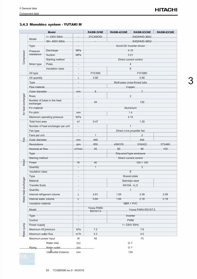
8/16/2019 Hitachi Yutaki Series 2016 Αντλίες θερμότητας
http://slidepdf.com/reader/full/hitachi-yutaki-series-2016- 93/256
3 General data
Component data
TCGB0098 rev.0 - 04/201683
3
3.4.3 Monobloc system - YUTAKI M
Model RASM-3VNE RASM-4(V)NE RASM-5(V)NE RASM-6(V)NE
C o m p r e s s o r
Model1~ 230V 50Hz - 2YC45KXD E402HHD-36A2
3N~ 400V 50Hz - - E402HHD-36D2
Type - Scroll DC Inverter driven
Pressureresistance
Discharge MPa 4.15
Suction MPa 2.21
Motor type
Starting method - Direct current control
Poles - 4
Insulation class - E
Oil type - FVC50K FVC68D
Oil quantity L 0.80 0.90
A i r h e a t e x c h a n
g e r
Type - Multi-pass cross-nned tube
Pipe material - Copper
Outer diameter mm 8 7
Rows - 2
Number of tubes in the heat
exchanger - 44 132
Fin material - Aluminium
Fin pitch mm 1.4
Maximum operating pressure MPa 4.15
Total front area m2 0.47 1.35
Number of heat exchanger per unit - 1
F a n
Fan type - Direct drive propeller fan
Fans per unit - 1 2
Outer diameter mm 449 544
Revolutions rpm 850 459/376 516/422 573/469
Nominal air ow m3/min 45 80 90 100
M o t o r
Type - Drip-proof type enclosure
Starting method - Direct current control
Power W 40 100 + 100
Quantity - 1 2
Insulation class - E
W a t e r h e a t e x c h a n g e r Type - Brazed plate
Material - Stainless steel
Transfer uids - R410A - H2O
Quantity - 1
Internal refrigerant volume L 0.81 1.55 2.09 2.09Internal water volume L 0.84 1.64 2.18 2.18
Insulation material - NBR + PVC
W a t e r p u m p
Model -Yonos PARA
RS15/7.0Yonos PARA RS15/7.5
Type - Inverter
Control - PWM
Power supply - 1~ 230V 50Hz
Maximum lift pressure kPa 7.2 7.6
Maximum water ow m3/h 3.3 4.0
Maximum power input W 45 75
Piping
Water inlet (in) G 1”
Water outlet (in) G 1”
Inlet/outlet distance mm 130
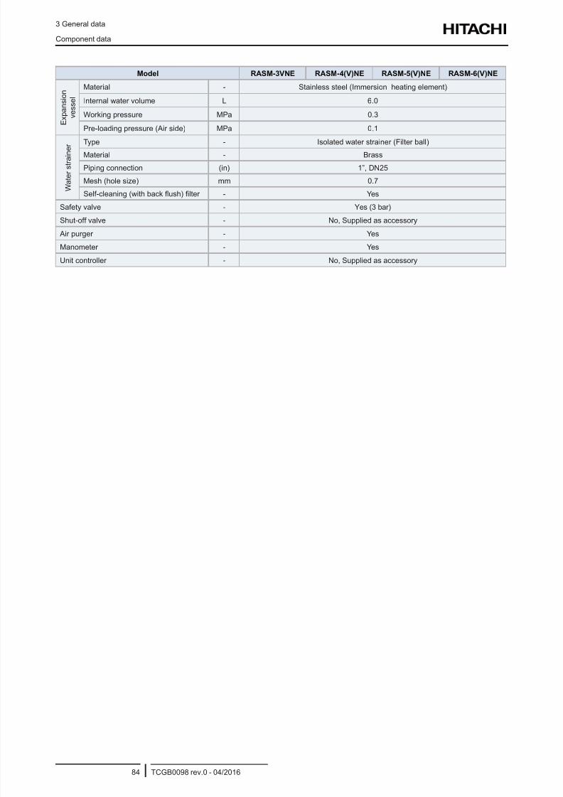
8/16/2019 Hitachi Yutaki Series 2016 Αντλίες θερμότητας
http://slidepdf.com/reader/full/hitachi-yutaki-series-2016- 94/256
3 General data
Component data
TCGB0098 rev.0 - 04/201684
Model RASM-3VNE RASM-4(V)NE RASM-5(V)NE RASM-6(V)NE
E x p a n s i o n
v e s s e l
Material - Stainless steel (Immersion heating element)
Internal water volume L 6.0
Working pressure MPa 0.3
Pre-loading pressure (Air side) MPa 0.1
W a t e r s t r a i n e r Type - Isolated water strainer (Filter ball)
Material - Brass
Piping connection (in) 1”, DN25
Mesh (hole size) mm 0.7
Self-cleaning (with back ush) lter - Yes
Safety valve - Yes (3 bar)
Shut-off valve - No, Supplied as accessory
Air purger - Yes
Manometer - Yes
Unit controller - No, Supplied as accessory
8/16/2019 Hitachi Yutaki Series 2016 Αντλίες θερμότητας
http://slidepdf.com/reader/full/hitachi-yutaki-series-2016- 95/256
3 General data
Electrical data
TCGB0098 rev.0 - 04/201685
3
3.5 Electrical data
3.5.1 Considerations
Key words:
• U: Power supply.
• PH: Phase.• IPT: Total input power.
• STC: Starting current: Less than maximum current.
• RNC: Running current.
• MC: Maximum current.
N O T E
• Heating conditions: Inlet/outlet water temperature: 30/35 ºC ; Outdoor ambient temperature (DB/WB): 7/6 ºC
• The compressor data shown in the tables below are based on a combined capacity of 100% of the power supplied.
• The “Maximum current” shown in the above table is the maximum total unit running current at the following conditions:
- Supply voltage: 90% of the rated voltage.
- Unit capacity: 100% at maximum operating conditions.
• The power supply cables must be sized to cover this maximum current value.
• Specications in these tables are subject to change without notice in order that HITACHI may bring the latest innovations to their
customers.
• Please refer to the general information, cautions and notes regarding protective devices (CB, ELB) throughout the “10. Elec-
trical and control settings” chapter.
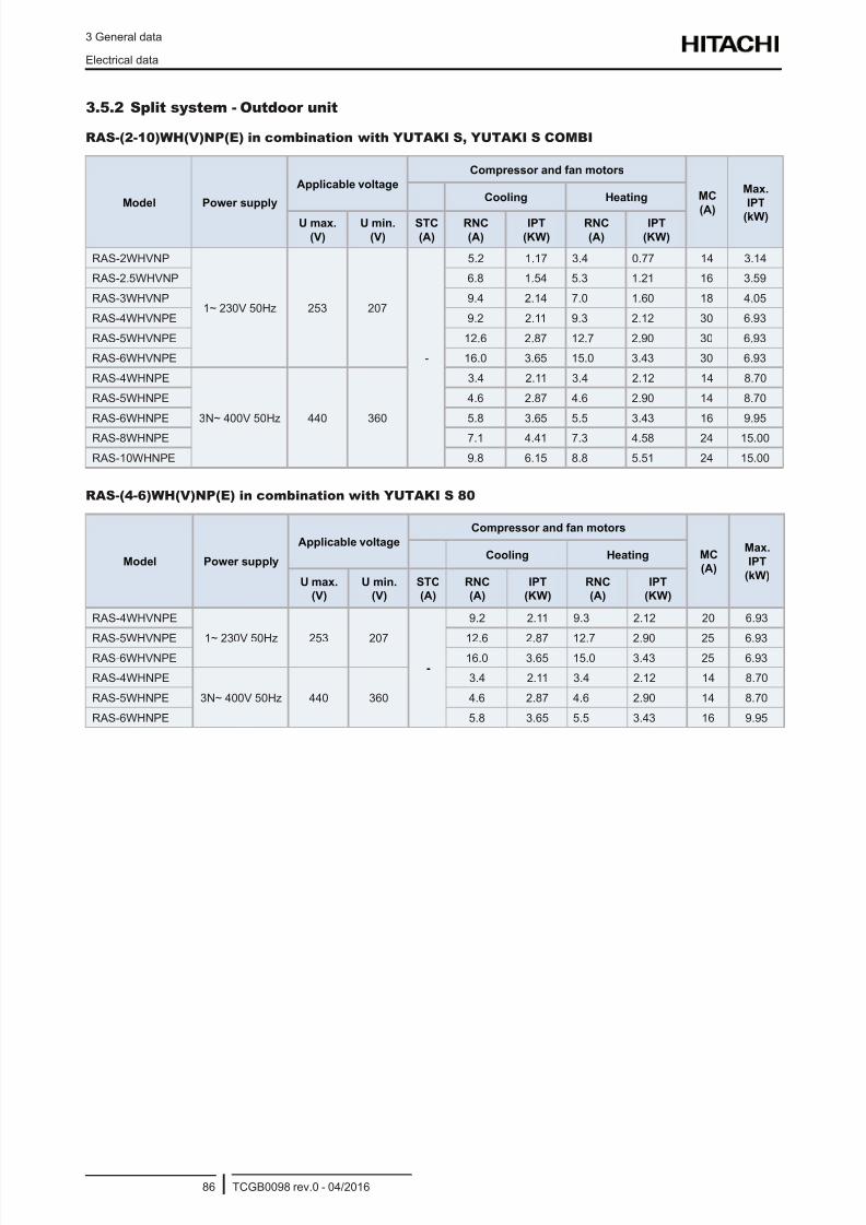
8/16/2019 Hitachi Yutaki Series 2016 Αντλίες θερμότητας
http://slidepdf.com/reader/full/hitachi-yutaki-series-2016- 96/256
3 General data
Electrical data
TCGB0098 rev.0 - 04/201686
3.5.2 Split system - Outdoor unit
RAS-(2-10)WH(V)NP(E) in combination with YUTAKI S, YUTAKI S COMBI
Model Power supply
Applicable voltage
Compressor and fan motors
MC
(A)
Max.
IPT
(kW)
Cooling Heating
U max.
(V)
U min.
(V)
STC
(A)
RNC
(A)
IPT
(KW)
RNC
(A)
IPT
(KW)
RAS-2WHVNP
1~ 230V 50Hz 253 207
-
5.2 1.17 3.4 0.77 14 3.14
RAS-2.5WHVNP 6.8 1.54 5.3 1.21 16 3.59
RAS-3WHVNP 9.4 2.14 7.0 1.60 18 4.05
RAS-4WHVNPE 9.2 2.11 9.3 2.12 30 6.93
RAS-5WHVNPE 12.6 2.87 12.7 2.90 30 6.93
RAS-6WHVNPE 16.0 3.65 15.0 3.43 30 6.93
RAS-4WHNPE
3N~ 400V 50Hz 440 360
3.4 2.11 3.4 2.12 14 8.70
RAS-5WHNPE 4.6 2.87 4.6 2.90 14 8.70
RAS-6WHNPE 5.8 3.65 5.5 3.43 16 9.95
RAS-8WHNPE 7.1 4.41 7.3 4.58 24 15.00
RAS-10WHNPE 9.8 6.15 8.8 5.51 24 15.00
RAS-(4-6)WH(V)NP(E) in combination with YUTAKI S 80
Model Power supply
Applicable voltage
Compressor and fan motors
MC
(A)
Max.
IPT
(kW)
Cooling Heating
U max.
(V)
U min.
(V)
STC
(A)
RNC
(A)
IPT
(KW)
RNC
(A)
IPT
(KW)
RAS-4WHVNPE
1~ 230V 50Hz 253 207
-
9.2 2.11 9.3 2.12 20 6.93
RAS-5WHVNPE 12.6 2.87 12.7 2.90 25 6.93RAS-6WHVNPE 16.0 3.65 15.0 3.43 25 6.93
RAS-4WHNPE
3N~ 400V 50Hz 440 360
3.4 2.11 3.4 2.12 14 8.70
RAS-5WHNPE 4.6 2.87 4.6 2.90 14 8.70
RAS-6WHNPE 5.8 3.65 5.5 3.43 16 9.95
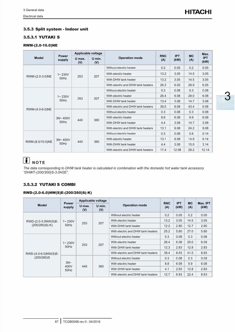
8/16/2019 Hitachi Yutaki Series 2016 Αντλίες θερμότητας
http://slidepdf.com/reader/full/hitachi-yutaki-series-2016- 97/256
3 General data
Electrical data
TCGB0098 rev.0 - 04/201687
3
3.5.3 Split system - Indoor unit
3.5.3.1 YUTAKI S
RWM-(2.0-10.0)NE
ModelPower
supply
Applicable voltage
Operation modeRNC
(A)
IPT
(kW)
MC
(A)
Max.
IPT(kW)
U max.(V)
U min.(V)
RWM-(2.0-3.0)NE1~ 230V
50Hz253 207
Without electric heater 0.2 0.05 0.2 0.05
With electric heater 13.2 3.05 14.5 3.05
With DHW tank heater 13.2 3.05 14.5 3.05
With electric and DHW tank heaters 26.3 6.05 28.9 6.05
RWM-(4.0-6.0)NE
1~ 230V
50Hz253 207
Without electric heater 0.3 0.08 0.3 0.08
With electric heater 26.4 6.08 29.0 6.08
With DHW tank heater 13.4 3.08 14.7 3.08
With electric and DHW tank heaters 39.5 9.08 43.4 9.08
3N~ 400V
50Hz440 360
Without electric heater 0.3 0.08 0.3 0.08
With electric heater 8.8 6.08 9.9 6.08
With DHW tank heater 4.4 3.08 14.7 3.08
With electric and DHW tank heaters 13.1 9.08 24.2 9.08
RWM-(8.0/10.0)NE3N~ 400V
50Hz440 360
Without electric heater 0.3 0.08 0.6 0.14
With electric heater 13.1 9.08 14.9 9.14
With DHW tank heater 4.4 3.08 15.0 3.14
With electric and DHW tank heaters 17.4 12.08 29.2 12.14
N O T E
The data corresponding to DHW tank heater is calculated in combination with the domestic hot water tank accessory
“DHWT-(200/300)S-3.0H2E”.
3.5.3.2 YUTAKI S COMBI
RWD-(2.0-6.0)NW(S)E-(200/260)S(-K)
ModelPower
supply
Applicable voltage
Operation modeRNC
(A)
IPT
(kW)
MC
(A)
Max. IPT
(kW)U max.
(V)
U min.
(V)
RWD-(2.0-3.0NW(S)E-(200/260)S(-K)
1~ 230V50Hz
253 207
Without electric heater 0.2 0.05 0.2 0.05
With electric heater 13.2 3.05 14.5 3.05
With DHW tank heater 12.2 2.80 12.7 2.80
With electric and DHW tank heaters 25.2 5.80 27.0 5.80
RWD-(4.0-6.0)NW(S)E-
(200/260)S
1~ 230V
50Hz253 207
Without electric heater 0.3 0.08 0.3 0.08
With electric heater 26.4 6.08 29.0 6.08
With DHW tank heater 12.3 2.83 12.8 2.83
With electric and DHW tank heaters 38.4 8.83 41.5 8.83
3N~
400V
50Hz
440 360
Without electric heater 0.3 0.08 0.3 0.08
With electric heater 8.8 6.08 9.9 6.08
With DHW tank heater 4.1 2.83 12.8 2.83
With electric and DHW tank heaters 12.7 8.83 22.4 8.83
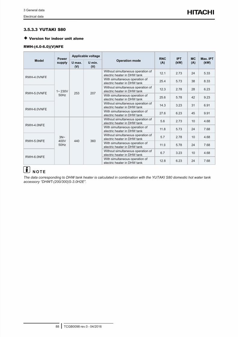
8/16/2019 Hitachi Yutaki Series 2016 Αντλίες θερμότητας
http://slidepdf.com/reader/full/hitachi-yutaki-series-2016- 98/256
3 General data
Electrical data
TCGB0098 rev.0 - 04/201688
3.5.3.3 YUTAKI S80
Version for indoor unit alone
RWH-(4.0-6.0)(V)NFE
Model Powersupply
Applicable voltage
Operation mode RNC(A)
IPT(kW)
MC(A)
Max. IPT(kW)U max.
(V)
U min.
(V)
RWH-4.0VNFE
1~ 230V
50Hz253 207
Without simultaneous operation of
electric heater in DHW tank12.1 2.73 24 5.33
With simultaneous operation of
electric heater in DHW tank25.4 5.73 38 8.33
RWH-5.0VNFE
Without simultaneous operation of
electric heater in DHW tank12.3 2.78 28 6.23
With simultaneous operation of
electric heater in DHW tank25.6 5.78 42 9.23
RWH-6.0VNFE
Without simultaneous operation ofelectric heater in DHW tank
14.3 3.23 31 6.91
With simultaneous operation ofelectric heater in DHW tank
27.6 6.23 45 9.91
RWH-4.0NFE
3N~400V
50Hz
440 360
Without simultaneous operation ofelectric heater in DHW tank
5.6 2.73 10 4.68
With simultaneous operation of
electric heater in DHW tank11.8 5.73 24 7.68
RWH-5.0NFE
Without simultaneous operation of
electric heater in DHW tank5.7 2.78 10 4.68
With simultaneous operation ofelectric heater in DHW tank
11.9 5.78 24 7.68
RWH-6.0NFE
Without simultaneous operation of
electric heater in DHW tank6.7 3.23 10 4.68
With simultaneous operation of
electric heater in DHW tank12.8 6.23 24 7.68
N O T E
The data corresponding to DHW tank heater is calculated in combination with the YUTAKI S80 domestic hot water tankaccessory “DHWT-(200/300)S-3.0H2E”.
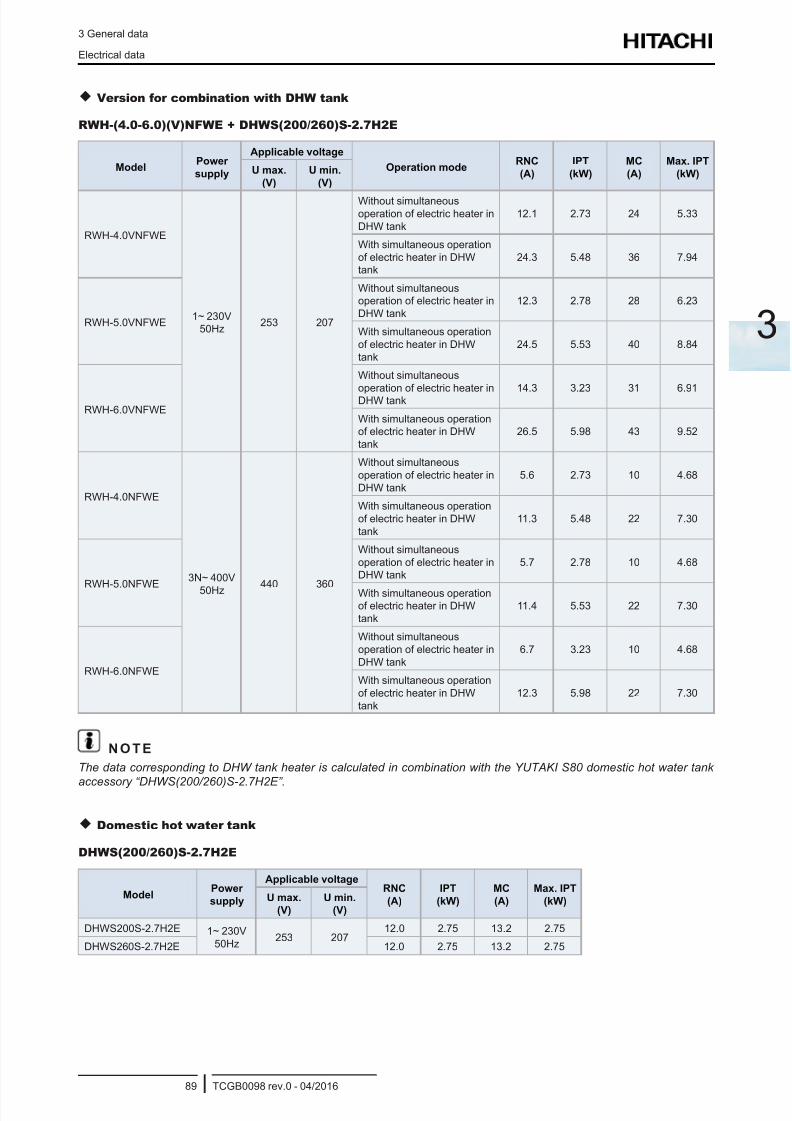
8/16/2019 Hitachi Yutaki Series 2016 Αντλίες θερμότητας
http://slidepdf.com/reader/full/hitachi-yutaki-series-2016- 99/256
3 General data
Electrical data
TCGB0098 rev.0 - 04/201689
3
Version for combination with DHW tank
RWH-(4.0-6.0)(V)NFWE + DHWS(200/260)S-2.7H2E
ModelPower
supply
Applicable voltage
Operation modeRNC
(A)
IPT
(kW)
MC
(A)
Max. IPT
(kW)U max.
(V)
U min.
(V)
RWH-4.0VNFWE
1~ 230V50Hz
253 207
Without simultaneous
operation of electric heater in
DHW tank
12.1 2.73 24 5.33
With simultaneous operation
of electric heater in DHWtank
24.3 5.48 36 7.94
RWH-5.0VNFWE
Without simultaneousoperation of electric heater in
DHW tank
12.3 2.78 28 6.23
With simultaneous operation
of electric heater in DHW
tank
24.5 5.53 40 8.84
RWH-6.0VNFWE
Without simultaneous
operation of electric heater inDHW tank 14.3 3.23 31 6.91
With simultaneous operationof electric heater in DHW
tank
26.5 5.98 43 9.52
RWH-4.0NFWE
3N~ 400V
50Hz 440 360
Without simultaneous
operation of electric heater in
DHW tank
5.6 2.73 10 4.68
With simultaneous operation
of electric heater in DHW
tank
11.3 5.48 22 7.30
RWH-5.0NFWE
Without simultaneous
operation of electric heater inDHW tank
5.7 2.78 10 4.68
With simultaneous operationof electric heater in DHW
tank
11.4 5.53 22 7.30
RWH-6.0NFWE
Without simultaneous
operation of electric heater in
DHW tank
6.7 3.23 10 4.68
With simultaneous operation
of electric heater in DHW
tank
12.3 5.98 22 7.30
N O T E
The data corresponding to DHW tank heater is calculated in combination with the YUTAKI S80 domestic hot water tank
accessory “DHWS(200/260)S-2.7H2E”.
Domestic hot water tank
DHWS(200/260)S-2.7H2E
ModelPower
supply
Applicable voltageRNC
(A)
IPT
(kW)
MC
(A)
Max. IPT
(kW)U max.
(V)
U min.
(V)
DHWS200S-2.7H2E 1~ 230V
50Hz253 207
12.0 2.75 13.2 2.75
DHWS260S-2.7H2E 12.0 2.75 13.2 2.75
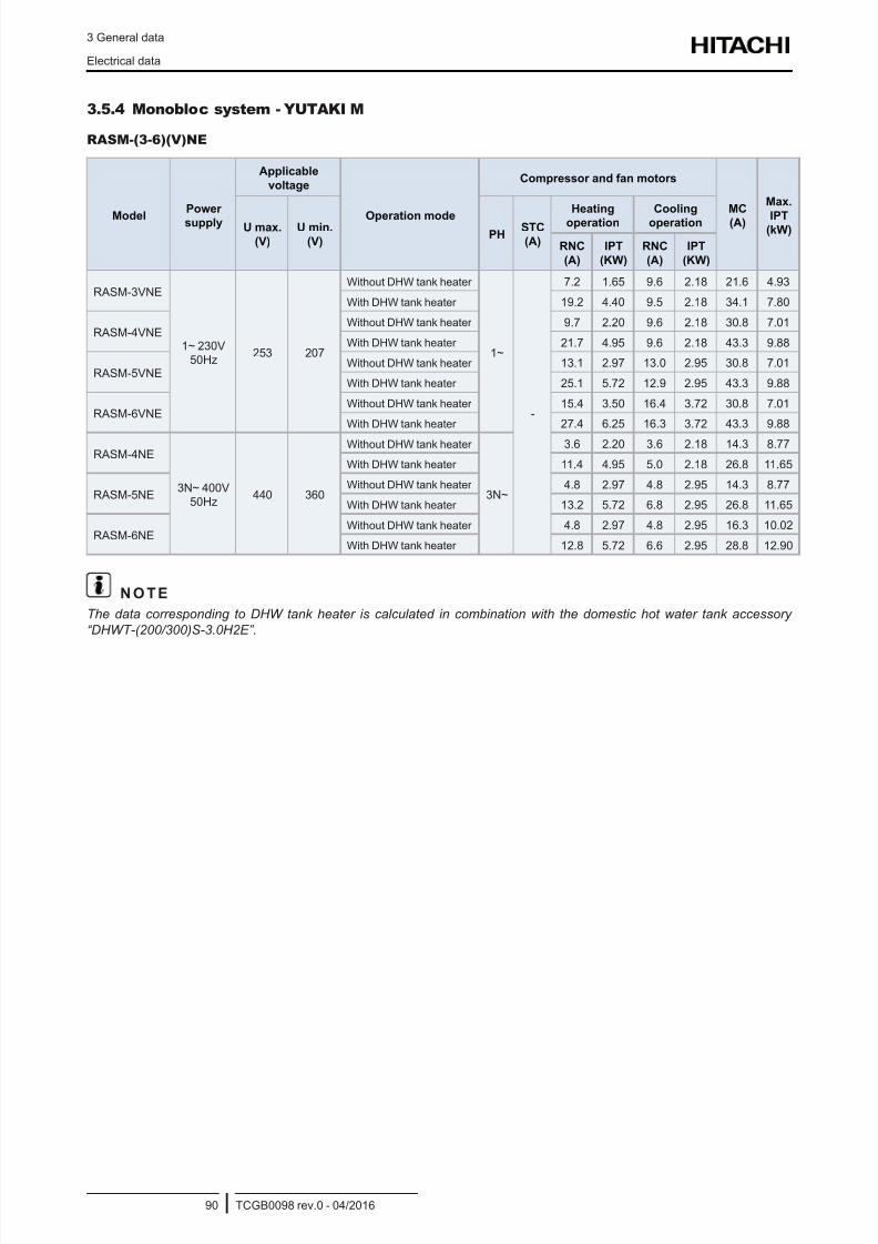
8/16/2019 Hitachi Yutaki Series 2016 Αντλίες θερμότητας
http://slidepdf.com/reader/full/hitachi-yutaki-series-2016- 100/256
3 General data
Electrical data
TCGB0098 rev.0 - 04/201690
3.5.4 Monobloc system - YUTAKI M
RASM-(3-6)(V)NE
ModelPower
supply
Applicable
voltage
Operation mode
Compressor and fan motors
MC
(A)
Max.
IPT(kW)U max.
(V)
U min.
(V)PH
STC
(A)
Heating
operation
Cooling
operation
RNC
(A)
IPT
(KW)
RNC
(A)
IPT
(KW)
RASM-3VNE
1~ 230V50Hz
253 207
Without DHW tank heater
1~
-
7.2 1.65 9.6 2.18 21.6 4.93
With DHW tank heater 19.2 4.40 9.5 2.18 34.1 7.80
RASM-4VNEWithout DHW tank heater 9.7 2.20 9.6 2.18 30.8 7.01
With DHW tank heater 21.7 4.95 9.6 2.18 43.3 9.88
RASM-5VNEWithout DHW tank heater 13.1 2.97 13.0 2.95 30.8 7.01
With DHW tank heater 25.1 5.72 12.9 2.95 43.3 9.88
RASM-6VNEWithout DHW tank heater 15.4 3.50 16.4 3.72 30.8 7.01
With DHW tank heater 27.4 6.25 16.3 3.72 43.3 9.88
RASM-4NE
3N~ 400V50Hz
440 360
Without DHW tank heater
3N~
3.6 2.20 3.6 2.18 14.3 8.77
With DHW tank heater 11.4 4.95 5.0 2.18 26.8 11.65
RASM-5NEWithout DHW tank heater 4.8 2.97 4.8 2.95 14.3 8.77
With DHW tank heater 13.2 5.72 6.8 2.95 26.8 11.65
RASM-6NEWithout DHW tank heater 4.8 2.97 4.8 2.95 16.3 10.02
With DHW tank heater 12.8 5.72 6.6 2.95 28.8 12.90
N O T E
The data corresponding to DHW tank heater is calculated in combination with the domestic hot water tank accessory
“DHWT-(200/300)S-3.0H2E”.
8/16/2019 Hitachi Yutaki Series 2016 Αντλίες θερμότητας
http://slidepdf.com/reader/full/hitachi-yutaki-series-2016- 101/256
4 Capacity and selection data
TCGB0098 rev.0 - 04/201691
4
4 . C a p a c i t y a n d s e l e c t i o n d a t a
Index
4.1 System selection procedure ..................................................................................................................92
4.1.1 Selection parameters .................................................................................................................................... 92
4.1.2 Selection procedure ...................................................................................................................................... 92
4.1.2.1 Description of procedure for YUTAKI S ........................................................................................ 94
4.1.2.2 Description of procedure for YUTAKI S COMBI.......................................................................... 100
4.1.2.3 Description of procedure for YUTAKI S 80 ................................................................................. 107
4.1.2.4 Selection procedure for YUTAKI M units .....................................................................................114
4.1.3 Flow rate and pressure drop check ..............................................................................................................119
4.2 System selection procedure (by Selection Software) .......................................................................... 120
4.2.1 Introduction .................................................................................................................................................. 120
4.2.2 How to use the Selection Software ............................................................................................................. 120
4.3 YUTAKI S ............................................................................................................................................ 139
4.3.1 Maximum heating capacity table (kW) (Integrated) ..................................................................................... 139
4.3.2 Maximum cooling capacity table (kW) ......................................................................................................... 141
4.4 YUTAKI S COMBI ............................................................................................................................... 142
4.4.1 Maximum heating capacity table (kW) (Integrated) ..................................................................................... 142
4.4.2 Maximum cooling capacity table (kW) ........................................................................................................ 144
4.5 YUTAKI S 80 ....................................................................................................................................... 145
4.5.1 Maximum heating capacity table (kW) (Integrated) ..................................................................................... 145
4.6 YUTAKI M ............................................................................................................................................ 146
4.6.1 Maximum heating capacity table (kW) (Integrated) ..................................................................................... 146
4.6.2 Maximum cooling capacity table (kW) ........................................................................................................ 147
4.7 Correction factors ................................................................................................................................ 148
4.7.1 Piping length correction factor .....................................................................................................................148
4.7.2 Correction factor owing to use of glycol (only for YUTAKI M)...................................................................... 151
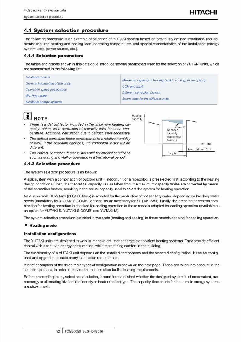
8/16/2019 Hitachi Yutaki Series 2016 Αντλίες θερμότητας
http://slidepdf.com/reader/full/hitachi-yutaki-series-2016- 102/256
4 Capacity and selection data
System selection procedure
TCGB0098 rev.0 - 04/201692
4.1 System selection procedure
The following procedure is an example of selection of YUTAKI system based on previously dened installation require -
ments: required heating and cooling load, operating temperatures and special characteristics of the installation (energy
system used, power source, etc.).
4.1.1 Selection parameters
The tables and graphs shown in this catalogue introduce several parameters used for the selection of YUTAKI units, which
are summarised in the following list:
Available models
General information of the units
Operation space possibilities
Working range
Available energy systems
Maximum capacity in heating (and in cooling, as an option)
COP and EER
Different correction factors
Sound data for the different units
N O T E• There is a defrost factor included in the Maximum heating ca-
pacity tables, as a correction of capacity data for each tem- perature. Additional calculation due to defrost is not necessary.
• The defrost correction factor corresponds to a relative humidity
of 85%. If the condition changes, the correction factor will be
different.
• The defrost correction factor is not valid for special conditions
such as during snowfall or operation in a transitional period
Heating
capacity
Reduced
capacity
due to frost
build-up
Time
Max. defrost 10 min.
1 cycle
4.1.2 Selection procedure
The system selection procedure is as follows:
A split system with a combination of outdoor unit + indoor unit or a monobloc is preselected rst, according to the heatingdesign conditions. Then, the theoretical capacity values taken from the maximum capacity tables are corrected by means
of the correction factors, resulting in the actual capacity used to select the system for heating operation.
Next, a suitable DHW tank (200/260 litres) is selected for the production of hot sanitary water, depending on the daily water
needs (mandatory for YUTAKI S COMBI, optional as an accessory for YUTAKI S80). Finally, the preselected system com-
bination for heating operation is checked for cooling operation in those models adapted for cooling operation (available as
an option for YUTAKI S, YUTAKI S COMBI and YUTAKI M).
The system selection procedure is divided in two parts (heating and cooling) in those models adapted for cooling operation.
Heating mode
Installation confgurations
The YUTAKI units are designed to work in monovalent, monoenergetic or bivalent heating systems. They provide efcient
control with a reduced energy consumption, while maintaining comfort in the building.
The functionality of a YUTAKI unit depends on the installed components and the selected conguration. It can be cong-
ured and upgraded to meet many installation requirements.
A brief description of the three main types of conguration is shown on the next page. These are taken into account in the
selection process, in order to provide the best solution for the heating requirements.
Before proceeding to any selection calculation, it must be established whether the designed system is of monovalent, mo-
noenergy or alternating bivalent (boiler only or heater+boiler) type. The capacity-time charts for these main energy systems
are shown next.
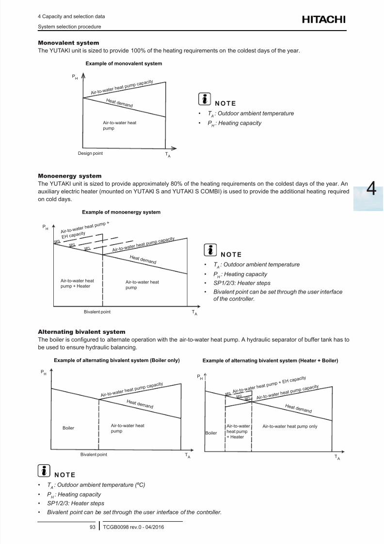
8/16/2019 Hitachi Yutaki Series 2016 Αντλίες θερμότητας
http://slidepdf.com/reader/full/hitachi-yutaki-series-2016- 103/256
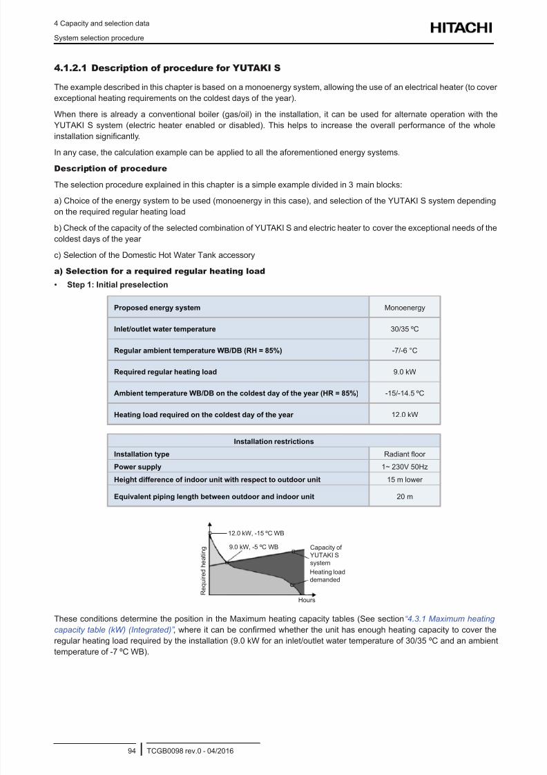
8/16/2019 Hitachi Yutaki Series 2016 Αντλίες θερμότητας
http://slidepdf.com/reader/full/hitachi-yutaki-series-2016- 104/256
4 Capacity and selection data
System selection procedure
TCGB0098 rev.0 - 04/201694
4.1.2.1 Description of procedure for YUTAKI S
The example described in this chapter is based on a monoenergy system, allowing the use of an electrical heater (to cover
exceptional heating requirements on the coldest days of the year).
When there is already a conventional boiler (gas/oil) in the installation, it can be used for alternate operation with the
YUTAKI S system (electric heater enabled or disabled). This helps to increase the overall performance of the whole
installation signicantly.
In any case, the calculation example can be applied to all the aforementioned energy systems.
Description of procedure
The selection procedure explained in this chapter is a simple example divided in 3 main blocks:
a) Choice of the energy system to be used (monoenergy in this case), and selection of the YUTAKI S system depending
on the required regular heating load
b) Check of the capacity of the selected combination of YUTAKI S and electric heater to cover the exceptional needs of the
coldest days of the year
c) Selection of the Domestic Hot Water Tank accessory
a) Selection for a required regular heating load
• Step 1: Initial preselection
Proposed energy system Monoenergy
Inlet/outlet water temperature 30/35 ºC
Regular ambient temperature WB/DB (RH = 85%) -7/-6 °C
Required regular heating load 9.0 kW
Ambient temperature WB/DB on the coldest day of the year (HR = 85%) -15/-14.5 ºC
Heating load required on the coldest day of the year 12.0 kW
Installation restrictions
Installation type Radiant oor
Power supply 1~ 230V 50Hz
Height difference of indoor unit with respect to outdoor unit 15 m lower
Equivalent piping length between outdoor and indoor unit 20 m
12.0 kW, -15 ºC WB
Capacity of
YUTAKI S
system
R e q u i r e d h e a t i n g
Hours
9.0 kW, -5 ºC WB
Heating load
demanded
These conditions determine the position in the Maximum heating capacity tables (See section “4.3.1 Maximum heating
capacity table (kW) (Integrated)” , where it can be conrmed whether the unit has enough heating capacity to cover the
regular heating load required by the installation (9.0 kW for an inlet/outlet water temperature of 30/35 ºC and an ambient
temperature of -7 ºC WB).
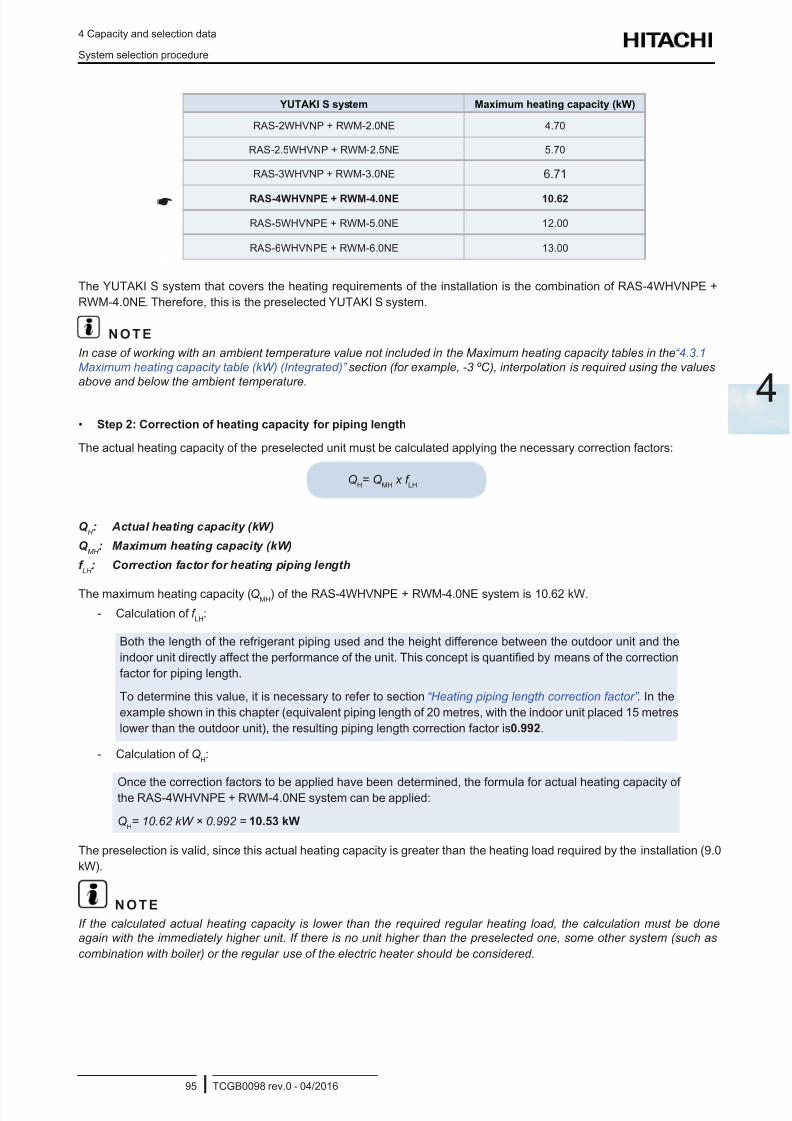
8/16/2019 Hitachi Yutaki Series 2016 Αντλίες θερμότητας
http://slidepdf.com/reader/full/hitachi-yutaki-series-2016- 105/256
8/16/2019 Hitachi Yutaki Series 2016 Αντλίες θερμότητας
http://slidepdf.com/reader/full/hitachi-yutaki-series-2016- 106/256
4 Capacity and selection data
System selection procedure
TCGB0098 rev.0 - 04/201696
b) Selection for the coldest days of the year (use of the auxiliary electric heater)
The previous calculation shows that the RAS-4WHVNPE + RWM-4.0NE system provides a heating capacity of 10.53 kW
(-7 ºC WB), which is greater than the regular heating load necessary of 9.0 kW, but does not reach the peak heating load of
12.0 kW (-15 ºC WB) required for the coldest days of the year. In these cases, the electric heater can provide the auxiliary
heating capacity to cover the peak heating load entirely.
The aim of this section is to check that the chosen energy system (Monoenergy) covers the exceptional heating requirementsfor the coldest days of the year.
• Step 1: Initial preselection
As the ambient temperature is lowered to -15 ºC, the Maximum heating capacity tables must be consulted again to
determine the maximum heating capacity that the RAS-4WHVNPE + RWM-4.0NE system can provide under these new
conditions.
The maximum heating capacity for an ambient temperature of -15 ºC WB and a water inlet/outlet temperature of 30/35 ºC
is 9.62 kW.
• Step 2: Heating capacity correction for piping length
The actual heating capacity of the selected system for the coldest days of the year is calculated by applying the correction
factors for defrost and piping length, following the previously used method.
QH= Q
MH x f
LH
Q H : Actual heating capacity (kW)
Q MH
: Maximum heating capacity (kW)
f LH
: Heating piping length correction factor
- Calculation of f LH
:
The same correction factor as in the previous section (0.992).
- Calculation of QH:
Once the corresponding correction factors have been determined, the formula for actual heating capacity
of the RAS-4WHVNPE + RWM-4.0NE system can be applied:
QH= 9.62 kW x 0.992 = 9.54 kW
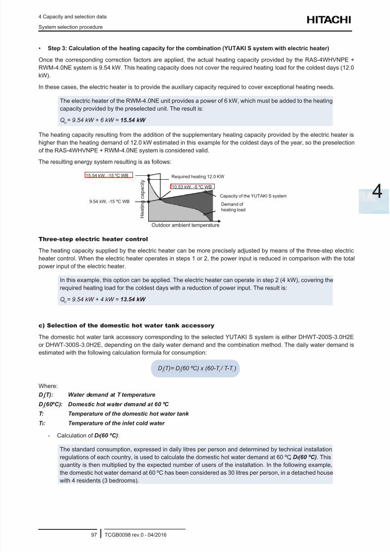
8/16/2019 Hitachi Yutaki Series 2016 Αντλίες θερμότητας
http://slidepdf.com/reader/full/hitachi-yutaki-series-2016- 107/256
4 Capacity and selection data
System selection procedure
TCGB0098 rev.0 - 04/201697
4
• Step 3: Calculation of the heating capacity for the combination (YUTAKI S system with electric heater)
Once the corresponding correction factors are applied, the actual heating capacity provided by the RAS-4WHVNPE +
RWM-4.0NE system is 9.54 kW. This heating capacity does not cover the required heating load for the coldest days (12.0
kW).
In these cases, the electric heater is to provide the auxiliary capacity required to cover exceptional heating needs.
The electric heater of the RWM-4.0NE unit provides a power of 6 kW, which must be added to the heating
capacity provided by the preselected unit. The result is:
QH= 9.54 kW + 6 kW = 15.54 kW
The heating capacity resulting from the addition of the supplementary heating capacity provided by the electric heater is
higher than the heating demand of 12.0 kW estimated in this example for the coldest days of the year, so the preselection
of the RAS-4WHVNPE + RWM-4.0NE system is considered valid.
The resulting energy system resulting is as follows:
15.54 kW, -15 ºC WB
Capacity of the YUTAKI S system
Required heating 12.0 KW
Outdoor ambient temperature
10.53 kW, -5 ºC WB
Demand of
heating load
9.54 kW, -15 ºC WB
H e a t i n g
c a p a c i t y
Three-step electric heater control
The heating capacity supplied by the electric heater can be more precisely adjusted by means of the three-step electric
heater control. When the electric heater operates in steps 1 or 2, the power input is reduced in comparison with the total
power input of the electric heater.
In this example, this option can be applied. The electric heater can operate in step 2 (4 kW), covering the
required heating load for the coldest days with a reduction of power input. The result is:Q
H= 9.54 kW + 4 kW = 13.54 kW
c) Selection of the domestic hot water tank accessory
The domestic hot water tank accessory corresponding to the selected YUTAKI S system is either DHWT-200S-3.0H2E
or DHWT-300S-3.0H2E, depending on the daily water demand and the combination method. The daily water demand is
estimated with the following calculation formula for consumption:
Di(T)= D
i(60 ºC) x (60-T
i / T-T
i )
Where:D
i (T): Water demand at T temperature
Di (60ºC): Domestic hot water demand at 60 ºC
T: Temperature of the domestic hot water tank
T I : Temperature of the inlet cold water
- Calculation of DI (60 ºC):
The standard consumption, expressed in daily litres per person and determined by technical installation
regulations of each country, is used to calculate the domestic hot water demand at 60 ºC, DI (60 ºC). This
quantity is then multiplied by the expected number of users of the installation. In the following example,
the domestic hot water demand at 60 ºC has been considered as 30 litres per person, in a detached house
with 4 residents (3 bedrooms).
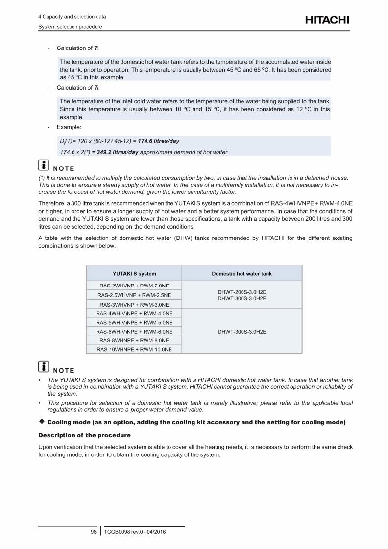
8/16/2019 Hitachi Yutaki Series 2016 Αντλίες θερμότητας
http://slidepdf.com/reader/full/hitachi-yutaki-series-2016- 108/256
4 Capacity and selection data
System selection procedure
TCGB0098 rev.0 - 04/201698
- Calculation of T :
The temperature of the domestic hot water tank refers to the temperature of the accumulated water inside
the tank, prior to operation. This temperature is usually between 45 ºC and 65 ºC. It has been considered
as 45 ºC in this example.
- Calculation of T I :
The temperature of the inlet cold water refers to the temperature of the water being supplied to the tank.
Since this temperature is usually between 10 ºC and 15 ºC, it has been considered as 12 ºC in this
example.
- Example:
Di(T)= 120 x (60-12
/ 45-12) = 174.6 litres/day
174.6 x 2(*) = 349.2 litres/day approximate demand of hot water
N O T E
(*) It is recommended to multiply the calculated consumption by two, in case that the installation is in a detached house.
This is done to ensure a steady supply of hot water. In the case of a multifamily installation, it is not necessary to in-
crease the forecast of hot water demand, given the lower simultaneity factor.
Therefore, a 300 litre tank is recommended when the YUTAKI S system is a combination of RAS-4WHVNPE + RWM-4.0NE
or higher, in order to ensure a longer supply of hot water and a better system performance. In case that the conditions of
demand and the YUTAKI S system are lower than those specications, a tank with a capacity between 200 litres and 300
litres can be selected, depending on the demand conditions.
A table with the selection of domestic hot water (DHW) tanks recommended by HITACHI for the different existing
combinations is shown below:
YUTAKI S system Domestic hot water tank
RAS-2WHVNP + RWM-2.0NE DHWT-200S-3.0H2E
DHWT-300S-3.0H2ERAS-2.5WHVNP + RWM-2.5NE
RAS-3WHVNP + RWM-3.0NE
RAS-4WH(V)NPE + RWM-4.0NE
DHWT-300S-3.0H2E
RAS-5WH(V)NPE + RWM-5.0NE
RAS-6WH(V)NPE + RWM-6.0NE
RAS-8WHNPE + RWM-8.0NE
RAS-10WHNPE + RWM-10.0NE
N O T E
• The YUTAKI S system is designed for combination with a HITACHI domestic hot water tank. In case that another tank
is being used in combination with a YUTAKI S system, HITACHI cannot guarantee the correct operation or reliability ofthe system.
• This procedure for selection of a domestic hot water tank is merely illustrative; please refer to the applicable local
regulations in order to ensure a proper water demand value.
Cooling mode (as an option, adding the cooling kit accessory and the setting for cooling mode)
Description of the procedure
Upon verication that the selected system is able to cover all the heating needs, it is necessary to perform the same check
for cooling mode, in order to obtain the cooling capacity of the system.
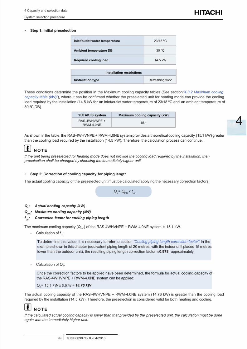
8/16/2019 Hitachi Yutaki Series 2016 Αντλίες θερμότητας
http://slidepdf.com/reader/full/hitachi-yutaki-series-2016- 109/256
4 Capacity and selection data
System selection procedure
TCGB0098 rev.0 - 04/201699
4
• Step 1: Initial preselection
Inlet/outlet water temperature 23/18 ºC
Ambient temperature DB 30 °C
Required cooling load 14.5 kW
Installation restrictions
Installation type Refreshing oor
These conditions determine the position in the Maximum cooling capacity tables (See section “4.3.2 Maximum cooling
capacity table (kW)” ), where it can be conrmed whether the preselected unit for heating mode can provide the cooling
load required by the installation (14.5 kW for an inlet/outlet water temperature of 23/18 ºC and an ambient temperature of
30 ºC DB).
YUTAKI S system Maximum cooling capacity (kW)
RAS-4WHVNPE +RWM-4.0NE 15.1
As shown in the table, the RAS-4WHVNPE + RWM-4.0NE system provides a theoretical cooling capacity (15.1 kW) greater
than the cooling load required by the installation (14.5 kW). Therefore, the calculation process can continue.
N O T E
If the unit being preselected for heating mode does not provide the cooling load required by the installation, then
preselection shall be changed by choosing the immediately higher unit.
• Step 2: Correction of cooling capacity for piping length
The actual cooling capacity of the preselected unit must be calculated applying the necessary correction factors:
QC= Q
MC x f
LC
Q C : Actual cooling capacity (kW)
Q MC
: Maximum cooling capacity (kW)
f LC
: Correction factor for cooling piping length
The maximum cooling capacity (QMC
) of the RAS-4WHVNPE + RWM-4.0NE system is 15.1 kW.
- Calculation of f LC
:
To determine this value, it is necessary to refer to section “Cooling piping length correction factor” . In the
example shown in this chapter (equivalent piping length of 20 metres, with the indoor unit placed 15 metres
lower than the outdoor unit), the resulting piping length correction factor is 0.978, approximately.
- Calculation of QC:
Once the correction factors to be applied have been determined, the formula for actual cooling capacity of
the RAS-4WHVNPE + RWM-4.0NE system can be applied:
QC= 15.1 kW x 0.978 = 14.76 kW
The actual cooling capacity of the RAS-4WHVNPE + RWM-4.0NE system (14.76 kW) is greater than the cooling load
required by the installation (14.5 kW). Therefore, the preselection is considered valid for both heating and cooling.
N O T E
If the calculated actual cooling capacity is lower than that provided by the preselected unit, the calculation must be done
again with the immediately higher unit.
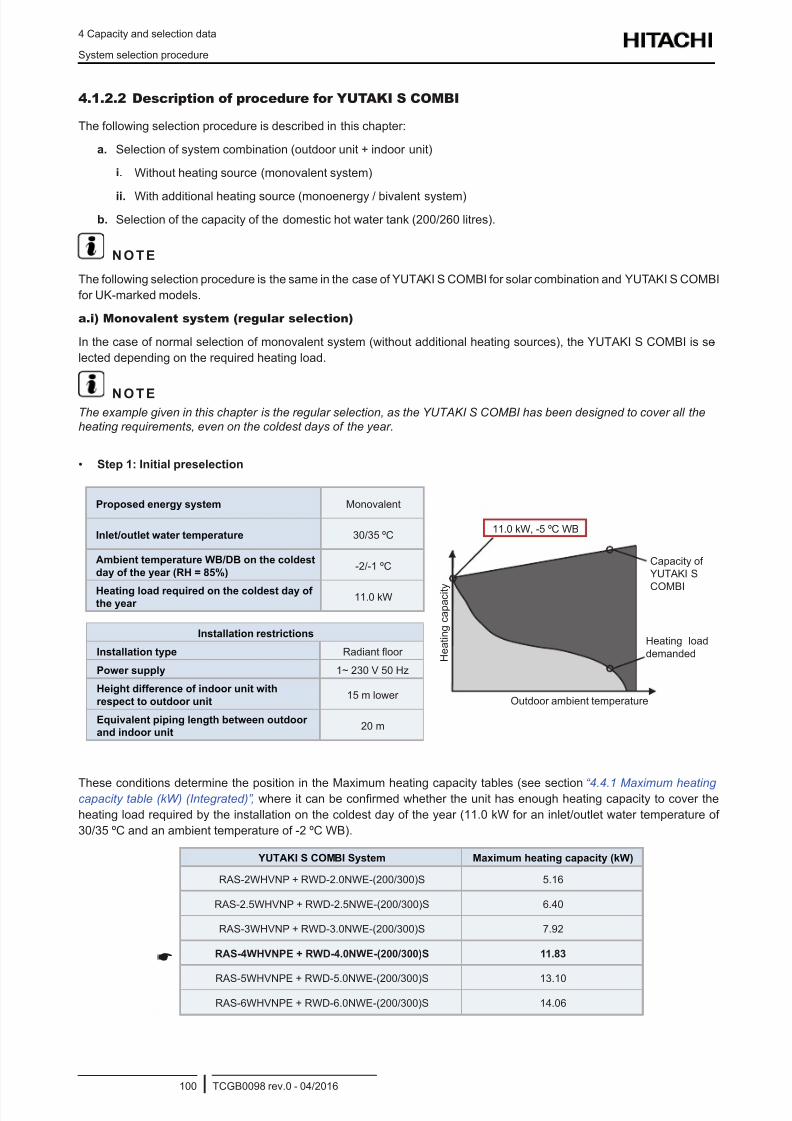
8/16/2019 Hitachi Yutaki Series 2016 Αντλίες θερμότητας
http://slidepdf.com/reader/full/hitachi-yutaki-series-2016- 110/256
4 Capacity and selection data
System selection procedure
TCGB0098 rev.0 - 04/2016100
4.1.2.2 Description of procedure for YUTAKI S COMBI
The following selection procedure is described in this chapter:
a. Selection of system combination (outdoor unit + indoor unit)
i. Without heating source (monovalent system)
ii. With additional heating source (monoenergy / bivalent system)
b. Selection of the capacity of the domestic hot water tank (200/260 litres).
N O T E
The following selection procedure is the same in the case of YUTAKI S COMBI for solar combination and YUTAKI S COMBI
for UK-marked models.
a.i) Monovalent system (regular selection)
In the case of normal selection of monovalent system (without additional heating sources), the YUTAKI S COMBI is se-
lected depending on the required heating load.
N O T EThe example given in this chapter is the regular selection, as the YUTAKI S COMBI has been designed to cover all theheating requirements, even on the coldest days of the year.
• Step 1: Initial preselection
Proposed energy system Monovalent
Inlet/outlet water temperature 30/35 ºC
Ambient temperature WB/DB on the coldest
day of the year (RH = 85%)-2/-1 ºC
Heating load required on the coldest day ofthe year
11.0 kW
11.0 kW, -5 ºC WB
Capacity of
YUTAKI S
COMBI
H e a t i n g
c a p a c i t y
Outdoor ambient temperature
Heating load
demanded
Installation restrictions
Installation type Radiant oor
Power supply 1~ 230 V 50 Hz
Height difference of indoor unit with
respect to outdoor unit15 m lower
Equivalent piping length between outdoor
and indoor unit20 m
These conditions determine the position in the Maximum heating capacity tables (see section “4.4.1 Maximum heating capacity table (kW) (Integrated)” , where it can be conrmed whether the unit has enough heating capacity to cover the
heating load required by the installation on the coldest day of the year (11.0 kW for an inlet/outlet water temperature of
30/35 ºC and an ambient temperature of -2 ºC WB).
YUTAKI S COMBI System Maximum heating capacity (kW)
RAS-2WHVNP + RWD-2.0NWE-(200/300)S 5.16
RAS-2.5WHVNP + RWD-2.5NWE-(200/300)S 6.40
RAS-3WHVNP + RWD-3.0NWE-(200/300)S 7.92
RAS-4WHVNPE + RWD-4.0NWE-(200/300)S 11.83
RAS-5WHVNPE + RWD-5.0NWE-(200/300)S 13.10
RAS-6WHVNPE + RWD-6.0NWE-(200/300)S 14.06
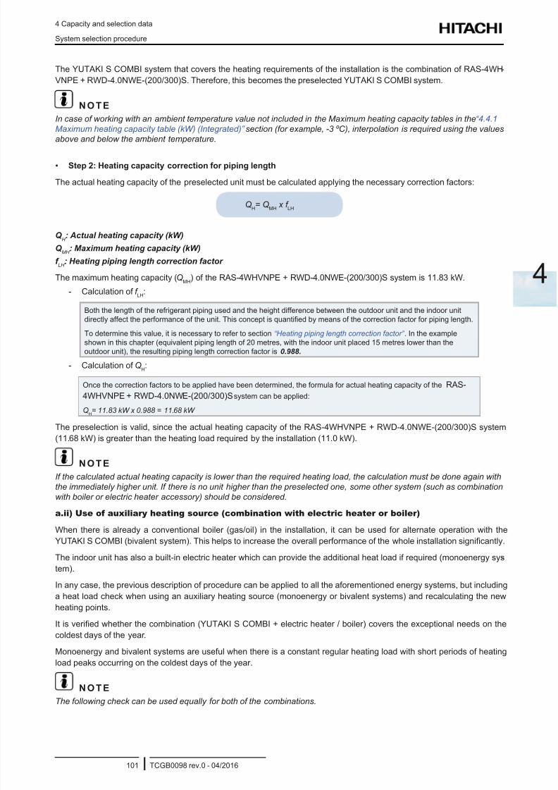
8/16/2019 Hitachi Yutaki Series 2016 Αντλίες θερμότητας
http://slidepdf.com/reader/full/hitachi-yutaki-series-2016- 111/256
4 Capacity and selection data
System selection procedure
TCGB0098 rev.0 - 04/2016101
4
The YUTAKI S COMBI system that covers the heating requirements of the installation is the combination of RAS-4WH -
VNPE + RWD-4.0NWE-(200/300)S. Therefore, this becomes the preselected YUTAKI S COMBI system.
N O T E
In case of working with an ambient temperature value not included in the Maximum heating capacity tables in the “4.4.1
Maximum heating capacity table (kW) (Integrated)” section (for example, -3 ºC), interpolation is required using the values
above and below the ambient temperature.
• Step 2: Heating capacity correction for piping length
The actual heating capacity of the preselected unit must be calculated applying the necessary correction factors:
QH= Q
MH x f
LH
Q H : Actual heating capacity (kW)
Q MH
: Maximum heating capacity (kW)
f LH
: Heating piping length correction factor
The maximum heating capacity (QMH) of the RAS-4WHVNPE + RWD-4.0NWE-(200/300)S system is 11.83 kW.
- Calculation of f LH
:
Both the length of the refrigerant piping used and the height difference between the outdoor unit and the indoor unit
directly affect the performance of the unit. This concept is quantied by means of the correction factor for piping length.
To determine this value, it is necessary to refer to section “Heating piping length correction factor” . In the example
shown in this chapter (equivalent piping length of 20 metres, with the indoor unit placed 15 metres lower than the
outdoor unit), the resulting piping length correction factor is 0.988.
- Calculation of QH:
Once the correction factors to be applied have been determined, the formula for actual heating capacity of the RAS-
4WHVNPE + RWD-4.0NWE-(200/300)S system can be applied:
QH
= 11.83 kW x 0.988 = 11.68 kW
The preselection is valid, since the actual heating capacity of the RAS-4WHVNPE + RWD-4.0NWE-(200/300)S system
(11.68 kW) is greater than the heating load required by the installation (11.0 kW).
N O T E
If the calculated actual heating capacity is lower than the required heating load, the calculation must be done again with
the immediately higher unit. If there is no unit higher than the preselected one, some other system (such as combination
with boiler or electric heater accessory) should be considered.
a.ii) Use of auxiliary heating source (combination with electric heater or boiler)
When there is already a conventional boiler (gas/oil) in the installation, it can be used for alternate operation with the
YUTAKI S COMBI (bivalent system). This helps to increase the overall performance of the whole installation signicantly.
The indoor unit has also a built-in electric heater which can provide the additional heat load if required (monoenergy sys-
tem).
In any case, the previous description of procedure can be applied to all the aforementioned energy systems, but including
a heat load check when using an auxiliary heating source (monoenergy or bivalent systems) and recalculating the new
heating points.
It is veried whether the combination (YUTAKI S COMBI + electric heater / boiler) covers the exceptional needs on the
coldest days of the year.
Monoenergy and bivalent systems are useful when there is a constant regular heating load with short periods of heating
load peaks occurring on the coldest days of the year.
N O T EThe following check can be used equally for both of the combinations.
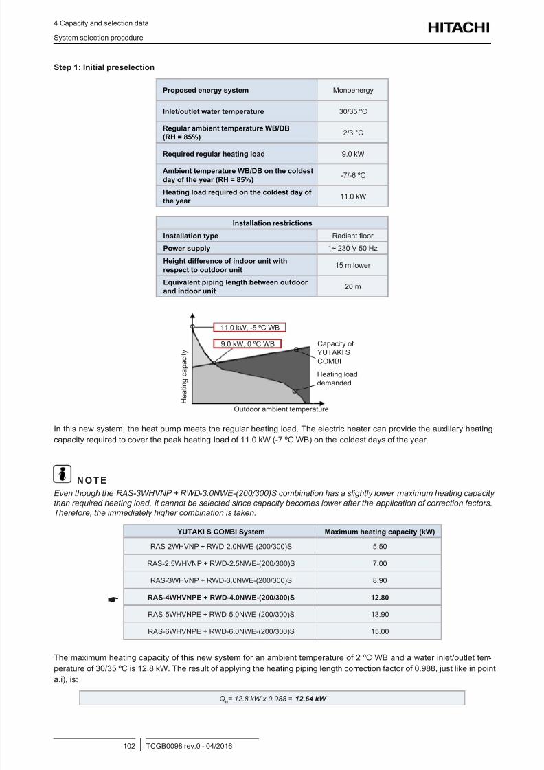
8/16/2019 Hitachi Yutaki Series 2016 Αντλίες θερμότητας
http://slidepdf.com/reader/full/hitachi-yutaki-series-2016- 112/256
4 Capacity and selection data
System selection procedure
TCGB0098 rev.0 - 04/2016102
Step 1: Initial preselection
Proposed energy system Monoenergy
Inlet/outlet water temperature 30/35 ºC
Regular ambient temperature WB/DB
(RH = 85%) 2/3 °C
Required regular heating load 9.0 kW
Ambient temperature WB/DB on the coldest
day of the year (RH = 85%)-7/-6 ºC
Heating load required on the coldest day of
the year 11.0 kW
Installation restrictions
Installation type Radiant oor
Power supply 1~ 230 V 50 Hz
Height difference of indoor unit with
respect to outdoor unit15 m lower
Equivalent piping length between outdoor
and indoor unit20 m
11.0 kW, -5 ºC WB
Capacity of
YUTAKI S
COMBI
H e a t i n g
c a p a c i t y
Outdoor ambient temperature
9.0 kW, 0 ºC WB
Heating load
demanded
In this new system, the heat pump meets the regular heating load. The electric heater can provide the auxiliary heating
capacity required to cover the peak heating load of 11.0 kW (-7 ºC WB) on the coldest days of the year.
N O T E
Even though the RAS-3WHVNP + RWD-3.0NWE-(200/300)S combination has a slightly lower maximum heating capacity
than required heating load, it cannot be selected since capacity becomes lower after the application of correction factors.Therefore, the immediately higher combination is taken.
YUTAKI S COMBI System Maximum heating capacity (kW)
RAS-2WHVNP + RWD-2.0NWE-(200/300)S 5.50
RAS-2.5WHVNP + RWD-2.5NWE-(200/300)S 7.00
RAS-3WHVNP + RWD-3.0NWE-(200/300)S 8.90
RAS-4WHVNPE + RWD-4.0NWE-(200/300)S 12.80
RAS-5WHVNPE + RWD-5.0NWE-(200/300)S 13.90
RAS-6WHVNPE + RWD-6.0NWE-(200/300)S 15.00
The maximum heating capacity of this new system for an ambient temperature of 2 ºC WB and a water inlet/outlet tem-
perature of 30/35 ºC is 12.8 kW. The result of applying the heating piping length correction factor of 0.988, just like in point
a.i), is:
QH= 12.8 kW x 0.988 = 12.64 kW
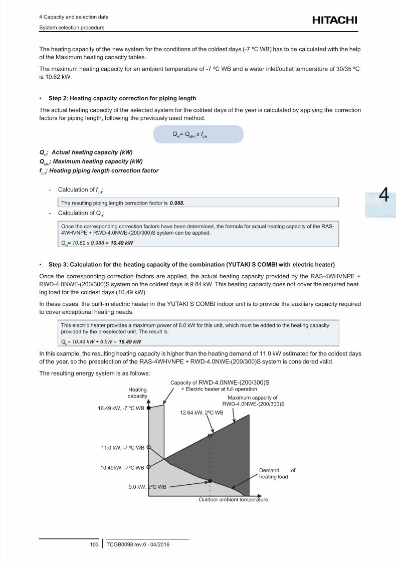
8/16/2019 Hitachi Yutaki Series 2016 Αντλίες θερμότητας
http://slidepdf.com/reader/full/hitachi-yutaki-series-2016- 113/256
4 Capacity and selection data
System selection procedure
TCGB0098 rev.0 - 04/2016103
4
The heating capacity of the new system for the conditions of the coldest days (-7 ºC WB) has to be calculated with the help
of the Maximum heating capacity tables.
The maximum heating capacity for an ambient temperature of -7 ºC WB and a water inlet/outlet temperature of 30/35 ºC
is 10.62 kW.
• Step 2: Heating capacity correction for piping length
The actual heating capacity of the selected system for the coldest days of the year is calculated by applying the correction
factors for piping length, following the previously used method.
QH= Q
MH x f
LH
Q H : Actual heating capacity (kW)
Q MH
: Maximum heating capacity (kW)
f LH
: Heating piping length correction factor
- Calculation of f LH
:
The resulting piping length correction factor is 0.988.
- Calculation of QH:
Once the corresponding correction factors have been determined, the formula for actual heating capacity of the RAS-
4WHVNPE + RWD-4.0NWE-(200/300)S system can be applied:
QH= 10.62 x 0.988 = 10.49 kW
• Step 3: Calculation for the heating capacity of the combination (YUTAKI S COMBI with electric heater)
Once the corresponding correction factors are applied, the actual heating capacity provided by the RAS-4WHVNPE +
RWD-4.0NWE-(200/300)S system on the coldest days is 9.84 kW. This heating capacity does not cover the required heat-
ing load for the coldest days (10.49 kW).In these cases, the built-in electric heater in the YUTAKI S COMBI indoor unit is to provide the auxiliary capacity required
to cover exceptional heating needs.
This electric heater provides a maximum power of 6.0 kW for this unit, which must be added to the heating capacity
provided by the preselected unit. The result is:
QH= 10.49 kW + 6 kW = 16.49 kW
In this example, the resulting heating capacity is higher than the heating demand of 11.0 kW estimated for the coldest days
of the year, so the preselection of the RAS-4WHVNPE + RWD-4.0NWE-(200/300)S system is considered valid.
The resulting energy system is as follows:
Capacity of RWD-4.0NWE-(200/300)S
+ Electric heater at full operation
Maximum capacity of
RWD-4.0NWE-(200/300)S
Heating
capacity
Outdoor ambient temperature
12.64 kW, 2ºC WB
11.0 kW, -7 ºC WB
16.49 kW, -7 ºC WB
10.49kW, -7ºC WB
9.0 kW, 2ºC WB
Demand of
heating load
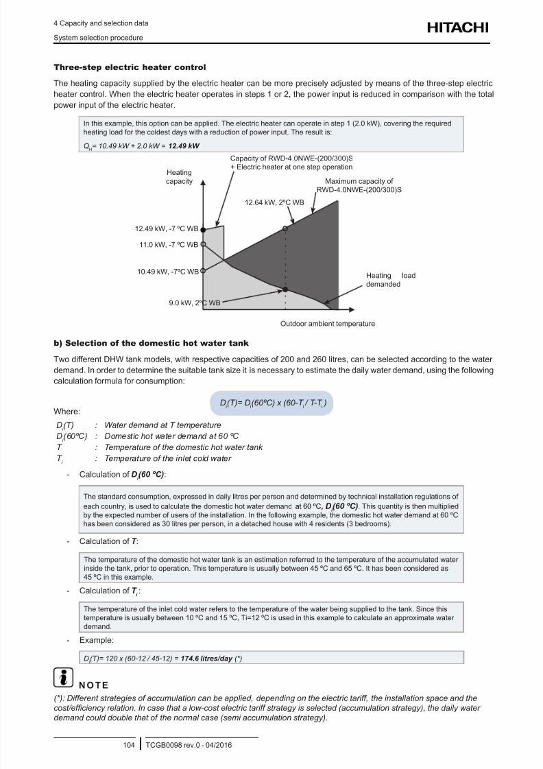
8/16/2019 Hitachi Yutaki Series 2016 Αντλίες θερμότητας
http://slidepdf.com/reader/full/hitachi-yutaki-series-2016- 114/256
4 Capacity and selection data
System selection procedure
TCGB0098 rev.0 - 04/2016104
Three-step electric heater control
The heating capacity supplied by the electric heater can be more precisely adjusted by means of the three-step electric
heater control. When the electric heater operates in steps 1 or 2, the power input is reduced in comparison with the total
power input of the electric heater.
In this example, this option can be applied. The electric heater can operate in step 1 (2.0 kW), covering the required
heating load for the coldest days with a reduction of power input. The result is:Q
H= 10.49 kW + 2.0 kW = 12.49 kW
Capacity of RWD-4.0NWE-(200/300)S
+ Electric heater at one step operation
Maximum capacity of
RWD-4.0NWE-(200/300)S
Heating
capacity
Outdoor ambient temperature
12.64 kW, 2ºC WB
11.0 kW, -7 ºC WB
12.49 kW, -7 ºC WB
10.49 kW, -7ºC WB
9.0 kW, 2ºC WB
Heating load
demanded
b) Selection of the domestic hot water tank
Two different DHW tank models, with respective capacities of 200 and 260 litres, can be selected according to the water
demand. In order to determine the suitable tank size it is necessary to estimate the daily water demand, using the following
calculation formula for consumption:
Di(T)= Di(60ºC) x (60-T i / T-T i )Where:
Di (T) : Water demand at T temperature
Di (60ºC) : Domestic hot water demand at 60 ºC
T : Temperature of the domestic hot water tank
T i
: Temperature of the inlet cold water
- Calculation of Di (60 ºC):
The standard consumption, expressed in daily litres per person and determined by technical installation regulations of
each country, is used to calculate the domestic hot water demand at 60 ºC, Di (60 ºC). This quantity is then multiplied
by the expected number of users of the installation. In the following example, the domestic hot water demand at 60 ºC
has been considered as 30 litres per person, in a detached house with 4 residents (3 bedrooms).
- Calculation of T :
The temperature of the domestic hot water tank is an estimation referred to the temperature of the accumulated water
inside the tank, prior to operation. This temperature is usually between 45 ºC and 65 ºC. It has been considered as
45 ºC in this example.
- Calculation of T i:
The temperature of the inlet cold water refers to the temperature of the water being supplied to the tank. Since this
temperature is usually between 10 ºC and 15 ºC, Ti=12 ºC is used in this example to calculate an approximate water
demand.
- Example:
Di(T)= 120 x (60-12
/ 45-12) = 174.6 litres/day (*)
N O T E
(*): Different strategies of accumulation can be applied, depending on the electric tariff, the installation space and the
cost/efciency relation. In case that a low-cost electric tariff strategy is selected (accumulation strategy), the daily water
demand could double that of the normal case (semi accumulation strategy).
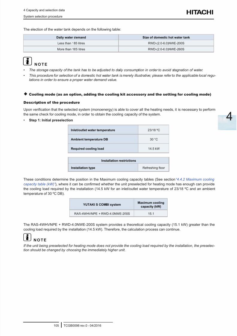
8/16/2019 Hitachi Yutaki Series 2016 Αντλίες θερμότητας
http://slidepdf.com/reader/full/hitachi-yutaki-series-2016- 115/256
4 Capacity and selection data
System selection procedure
TCGB0098 rev.0 - 04/2016105
4
The election of the water tank depends on the following table:
Daily water demand Size of domestic hot water tank
Less than 185 litres RWD-(2.0-6.0)NWE-200S
More than 185 litres RWD-(2.0-6.0)NWE-260S
N O T E
• The storage capacity of the tank has to be adjusted to daily consumption in order to avoid stagnation of water.
• This procedure for selection of a domestic hot water tank is merely illustrative; please refer to the applicable local regu-
lations in order to ensure a proper water demand value.
Cooling mode (as an option, adding the cooling kit accessory and the setting for cooling mode)
Description of the procedure
Upon verication that the selected system (monoenergy) is able to cover all the heating needs, it is necessary to perform
the same check for cooling mode, in order to obtain the cooling capacity of the system.
• Step 1: Initial preselection
Inlet/outlet water temperature 23/18 ºC
Ambient temperature DB 30 °C
Required cooling load 14.5 kW
Installation restrictions
Installation type Refreshing oor
These conditions determine the position in the Maximum cooling capacity tables (See section “4.4.2 Maximum cooling
capacity table (kW)” ), where it can be conrmed whether the unit preselected for heating mode has enough can provide
the cooling load required by the installation (14.5 kW for an inlet/outlet water temperature of 23/18 ºC and an ambient
temperature of 30 ºC DB).
YUTAKI S COMBI systemMaximum cooling
capacity (kW)
RAS-4WHVNPE + RWD-4.0NWE-200S 15.1
The RAS-4WHVNPE + RWD-4.0NWE-200S system provides a theoretical cooling capacity (15.1 kW) greater than the
cooling load required by the installation (14.5 kW). Therefore, the calculation process can continue.
N O T E
If the unit being preselected for heating mode does not provide the cooling load required by the installation, the preselec-
tion should be changed by choosing the immediately higher unit.
8/16/2019 Hitachi Yutaki Series 2016 Αντλίες θερμότητας
http://slidepdf.com/reader/full/hitachi-yutaki-series-2016- 116/256
4 Capacity and selection data
System selection procedure
TCGB0098 rev.0 - 04/2016106
• Step 2: Cooling capacity correction for defrost and piping length
The actual cooling capacity of the preselected unit is calculated by applying the necessary correction factors:
QC= Q
MC x f
LC
Q C : Actual cooling capacity (kW)Q
MC : Maximum cooling capacity (kW)
f LC
: Cooling piping length correction factor
The maximum cooling capacity (QMC
) of the RAS-4WHVNPE + RWD-4.0NWE-200S system is 15.1 kW.
- Calculation of f LC
:
To determine this value, it is necessary to refer to section “Cooling piping length correction factor” . In the
example shown in this chapter (equivalent piping length of 20 metres, with the indoor unit placed 15 metres
lower than the outdoor unit), the resulting piping length correction factor is 0.978 approximately.
- Calculation of QC:
Once the correction factors to be applied have been determined, the formula for actual cooling capacity of
the RAS-4WHVNPE + RWD-4.0NWE-200S system can be applied:
QC= 15.1 kW x 0.978 = 14.76 kW
The preselection is valid both for heating and cooling, since the actual cooling capacity of the RAS-4WHVNPE + RWD-
4.0NWE-200S system (11.25 kW) is greater than the cooling load required by the installation (14.5 kW).
N O T E
If the calculated actual cooling capacity is lower than that provided by the preselected unit, the calculation must be done
again with the immediately higher unit.
8/16/2019 Hitachi Yutaki Series 2016 Αντλίες θερμότητας
http://slidepdf.com/reader/full/hitachi-yutaki-series-2016- 117/256
4 Capacity and selection data
System selection procedure
TCGB0098 rev.0 - 04/2016107
4
4.1.2.3 Description of procedure for YUTAKI S 80
The following selection procedure is described in this chapter:
c. Selection of system combination (outdoor unit + indoor unit)
i. Without heating source (monovalent system)
ii. With additional heating source (monoenergy / bivalent system)
a. Selection of the capacity of the domestic hot water tank accessory (optional).
a.i) Monovalent system (regular selection)
In the case of normal selection of monovalent system (without additional heating sources), the YUTAKI S80 is selected
depending on the required heating load.
N O T E
The example given in this chapter is the regular selection as the YUTAKI S80 has been designed to cover all the heating
requirements, even on the coldest days of the year.
• Step 1: Initial preselection
Proposed energy system Monovalent
Inlet/outlet water temperature 47/55ºC
Ambient temperature WB/DB in the coldest
day of the year (RH = 85%)-7/-6ºC
Heating load required on the coldest day of
the year 13.5 kW
13.5 kW, -7ºC WB
Capacity of
YUTAKI S80
H e a t i n g
c a p a c i t y
Outdoor ambient temperature
Heating load
demanded
Installation restrictions
Installation type Radiant oor
Power supply 1~ 230V 50Hz
Height difference of indoor unit with respect
to outdoor unit15 m or lower
Equivalent piping length between outdoor and
indoor unit20 m
These conditions determine the position in the Maximum heating capacity tables (see section “4.5.1 Maximum heating
capacity table (kW) (Integrated)” ), where it can be conrmed whether the unit has enough heating capacity to cover the
heating load required by the installation on the coldest day of the year (13.5 kW for an inlet/outlet water temperature of
47/55 ºC and an ambient temperature of -7 ºC WB).
YUTAKI S80 Maximum heating capacity (kW)
RAS-4WHVNPE + RWH-4.0VNF(W)E 12.50
RAS-5WHVNPE + RWH-5.0VNF(W)E 14.50
RAS-6WHVNPE + RWH-6.0VNF(W)E 16.10
N O T E
Even though the RAS-4WHVNPE + RWH-4.0VNF(W)E combination has a slightly higher maximum heating capacity than
the required heating load, it is necessary to select the immediately higher combination since heating capacity becomeslower after applying the correction factors in step 2.
8/16/2019 Hitachi Yutaki Series 2016 Αντλίες θερμότητας
http://slidepdf.com/reader/full/hitachi-yutaki-series-2016- 118/256
4 Capacity and selection data
System selection procedure
TCGB0098 rev.0 - 04/2016108
According to the table, the YUTAKI S80 system that covers the heating requirements of the installation is the combination
of RAS-5WHVNPE + RWH-5.0VNF(W)E. Therefore, this becomes the preselected YUTAKI S80 system.
N O T E
In case of working with an ambient temperature value not included in the Maximum heating capacity tables in the “4.5.1
Maximum heating capacity table (kW) (Integrated)” section (for example, -3ºC), interpolation is required using the values
above and below the ambient temperature.
• Step 2: Correction of heating capacity for piping length
The actual heating capacity of the preselected unit must be calculated applying the necessary correction factors:
QH = Q
MH x f
LH
Q H
: Actual heating capacity (kW)
Q MH
: Maximum heating capacity (kW)
f LH : Correction factor for heating piping length
The maximum heating capacity (QMH
) of the RAS-5WHVNPE + RWH-5.0VNF(W)E system is 14.50 kW.
- Calculation of f LH
:
Both the length of the refrigerant piping used and the height difference between the outdoor unit and the indoor unit
directly affect the performance of the unit. This concept is quantied by means of the correction factor for piping length.
To determine this value, it is necessary to refer to section “Heating piping length correction factor” . In the example
shown in this chapter (equivalent piping length of 20 metres, with the indoor unit placed 15 metres lower than the
outdoor unit), the resulting piping length correction factor is 0.988.
- Calculation of QH:
Once the correction factors to be applied have been determined, the formula for actual heating capacity of the RAS-
5WHVNPE + RWH-5.0VNF(W)E system can be applied:Q
H= 14.50 kW x 0.988 = 14.33 kW
The preselection is valid, since the actual heating capacity of the RAS-5WHVNPE + RWH-5.0VNF(W)E system (14.33 kW)
is greater than the heating load required by the installation (13.5 kW).
N O T E
If the calculated actual heating capacity is lower than the required heating load, the calculation must be done again with
the immediately higher unit. If there is no unit higher than the preselected one, some other system (such as combination
with boiler or electric heater accessory) should be considered.
a.ii) Use of auxiliary heating source (combination with electric heater or boiler)
When there is already a conventional boiler (gas/oil) in the installation, it can be used for alternate operation with the
YUTAKI S80 (bivalent system). This helps to increase the overall performance of the whole installation signicantly.
An electric heater can also be installed as an accessory for the monoenergy system, if an additional heat load is required.
In any case, the previous description of procedure can be applied to all the aforementioned energy systems, but including
a heat load check when using an auxiliary heating source (monoenergy or bivalent systems) and recalculating the new
heating points.
It is veried whether the combination (YUTAKI S80 + electric heater / boiler) covers the exceptional needs on the coldest
days of the year.
Monoenergy and bivalent systems are useful when there is a constant regular heating load with short periods of heating
load peaks occurring on the coldest days of the year.
N O T E
The following check can be used equally for both of the combinations.
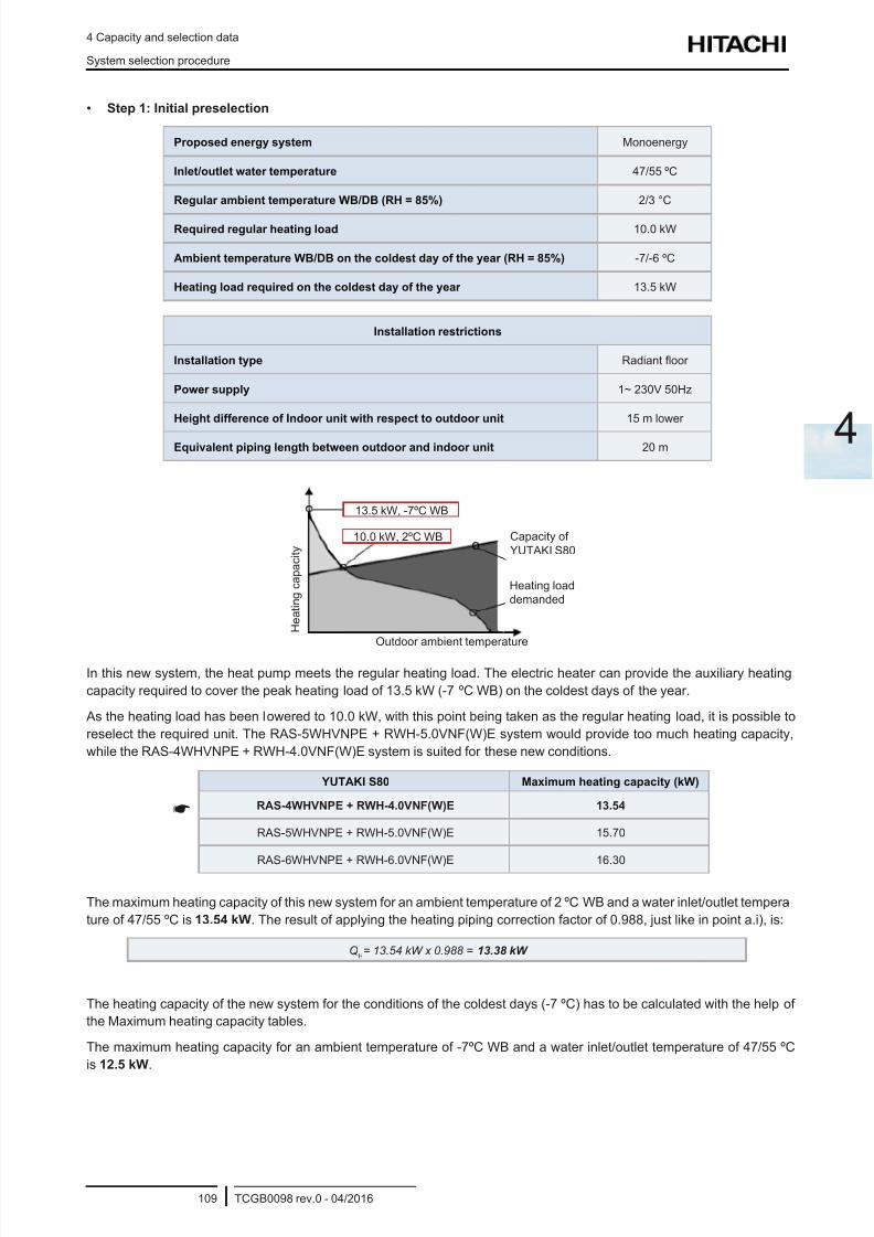
8/16/2019 Hitachi Yutaki Series 2016 Αντλίες θερμότητας
http://slidepdf.com/reader/full/hitachi-yutaki-series-2016- 119/256
4 Capacity and selection data
System selection procedure
TCGB0098 rev.0 - 04/2016109
4
• Step 1: Initial preselection
Proposed energy system Monoenergy
Inlet/outlet water temperature 47/55 ºC
Regular ambient temperature WB/DB (RH = 85%) 2/3 °C
Required regular heating load 10.0 kW
Ambient temperature WB/DB on the coldest day of the year (RH = 85%) -7/-6 ºC
Heating load required on the coldest day of the year 13.5 kW
Installation restrictions
Installation type Radiant oor
Power supply 1~ 230V 50Hz
Height difference of Indoor unit with respect to outdoor unit 15 m lower
Equivalent piping length between outdoor and indoor unit 20 m
13.5 kW, -7ºC WB
Capacity of
YUTAKI S80
H e a t i n g
c a p a c i t y
Outdoor ambient temperature
10.0 kW, 2ºC WB
Heating load
demanded
In this new system, the heat pump meets the regular heating load. The electric heater can provide the auxiliary heating
capacity required to cover the peak heating load of 13.5 kW (-7 ºC WB) on the coldest days of the year.
As the heating load has been lowered to 10.0 kW, with this point being taken as the regular heating load, it is possible to
reselect the required unit. The RAS-5WHVNPE + RWH-5.0VNF(W)E system would provide too much heating capacity,
while the RAS-4WHVNPE + RWH-4.0VNF(W)E system is suited for these new conditions.
YUTAKI S80 Maximum heating capacity (kW)
RAS-4WHVNPE + RWH-4.0VNF(W)E 13.54
RAS-5WHVNPE + RWH-5.0VNF(W)E 15.70
RAS-6WHVNPE + RWH-6.0VNF(W)E 16.30
The maximum heating capacity of this new system for an ambient temperature of 2 ºC WB and a water inlet/outlet tempera-
ture of 47/55 ºC is 13.54 kW. The result of applying the heating piping correction factor of 0.988, just like in point a.i), is:
QH= 13.54 kW x 0.988 = 13.38 kW
The heating capacity of the new system for the conditions of the coldest days (-7 ºC) has to be calculated with the help of
the Maximum heating capacity tables.
The maximum heating capacity for an ambient temperature of -7ºC WB and a water inlet/outlet temperature of 47/55 ºC
is 12.5 kW.
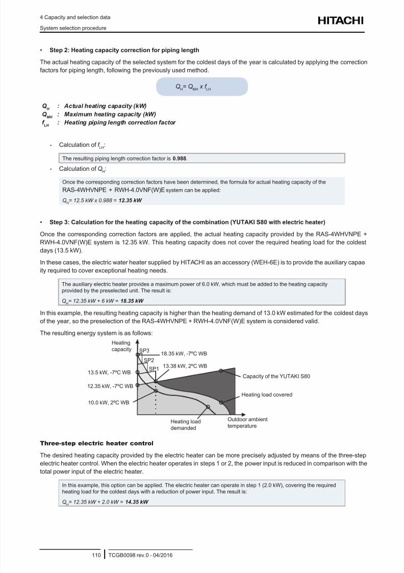
8/16/2019 Hitachi Yutaki Series 2016 Αντλίες θερμότητας
http://slidepdf.com/reader/full/hitachi-yutaki-series-2016- 120/256
4 Capacity and selection data
System selection procedure
TCGB0098 rev.0 - 04/2016110
• Step 2: Heating capacity correction for piping length
The actual heating capacity of the selected system for the coldest days of the year is calculated by applying the correction
factors for piping length, following the previously used method.
QH= Q
MH x f
LH
Q H
: Actual heating capacity (kW)
Q MH
: Maximum heating capacity (kW)
f LH
: Heating piping length correction factor
- Calculation of f LH
:
The resulting piping length correction factor is 0.988.
- Calculation of QH:
Once the corresponding correction factors have been determined, the formula for actual heating capacity of the
RAS-4WHVNPE + RWH-4.0VNF(W)E system can be applied:
QH= 12.5 kW x 0.988 = 12.35 kW
• Step 3: Calculation for the heating capacity of the combination (YUTAKI S80 with electric heater)
Once the corresponding correction factors are applied, the actual heating capacity provided by the RAS-4WHVNPE +
RWH-4.0VNF(W)E system is 12.35 kW. This heating capacity does not cover the required heating load for the coldest
days (13.5 kW).
In these cases, the electric water heater supplied by HITACHI as an accessory (WEH-6E) is to provide the auxiliary capac-
ity required to cover exceptional heating needs.
The auxiliary electric heater provides a maximum power of 6.0 kW, which must be added to the heating capacity
provided by the preselected unit. The result is:
QH= 12.35 kW + 6 kW = 18.35 kW
In this example, the resulting heating capacity is higher than the heating demand of 13.0 kW estimated for the coldest days
of the year, so the preselection of the RAS-4WHVNPE + RWH-4.0VNF(W)E system is considered valid.
The resulting energy system is as follows:
18.35 kW, -7ºC WB
Capacity of the YUTAKI S80
Heating
capacity
Outdoor ambient
temperature
13.38 kW, 2ºC WB
Heating load covered
12.35 kW, -7ºC WB
13.5 kW, -7ºC WB
10.0 kW, 2ºC WB
Heating load
demanded
SP1
SP2
SP3
Three-step electric heater control
The desired heating capacity provided by the electric heater can be more precisely adjusted by means of the three-step
electric heater control. When the electric heater operates in steps 1 or 2, the power input is reduced in comparison with the
total power input of the electric heater.
In this example, this option can be applied. The electric heater can operate in step 1 (2.0 kW), covering the required
heating load for the coldest days with a reduction of power input. The result is:
QH= 12.35 kW + 2.0 kW = 14.35 kW
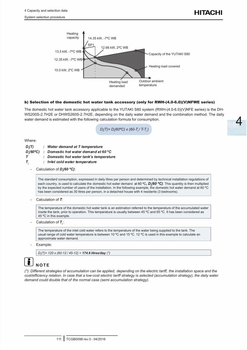
8/16/2019 Hitachi Yutaki Series 2016 Αντλίες θερμότητας
http://slidepdf.com/reader/full/hitachi-yutaki-series-2016- 121/256
4 Capacity and selection data
System selection procedure
TCGB0098 rev.0 - 04/2016111
4
SP1
14.35 kW, -7ºC WB
Capacity of the YUTAKI S80
Heating
capacity
Outdoor ambient
temperature
12.66 kW, 2ºC WB
Heating load covered12.35 kW, -7ºC WB
13.5 kW, -7ºC WB
10.0 kW, 2ºC WB
Heating load
demanded
b) Selection of the domestic hot water tank accessory (only for RWH-(4.0-6.0)(V)NFWE series)
The domestic hot water tank accessory applicable to the YUTAKI S80 system (RWH-(4.0-6.0)(V)NFE series) is the DH-
WS200S-2.7H2E or DHWS260S-2.7H2E, depending on the daily water demand and the combination method. The daily
water demand is estimated with the following calculation formula for consumption.
Di(T)= D
i(60ºC) x (60-T
i / T-T
i )
Where:
Di (T) : Water demand at T temperature
Di (60ºC) : Domestic hot water demand at 60 ºC
T : Domestic hot water tank’s temperature
T i
: Inlet cold water temperature
- Calculation of Di (60 ºC):
The standard consumption, expressed in daily litres per person and determined by technical installation regulations of
each country, is used to calculate the domestic hot water demand at 60 ºC, Di (60 ºC). This quantity is then multipliedby the expected number of users of the installation. In the following example, the domestic hot water demand at 60 ºC
has been considered as 30 litres per person, in a detached house with 4 residents (3 bedrooms).
- Calculation of T :
The temperature of the domestic hot water tank is an estimation referred to the temperature of the accumulated water
inside the tank, prior to operation. This temperature is usually between 45 ºC and 65 ºC. It has been considered as
45 ºC in this example.
- Calculation of T i:
The temperature of the inlet cold water refers to the temperature of the water being supplied to the tank. The
usual range of cold water temperature is between 10 ºC and 15 ºC. 12 ºC is used in this example to calculate an
approximate water demand.
- Example:
Di(T)= 120 x (60-12
/ 45-12) = 174.6 litres/day (*)
N O T E
(*): Different strategies of accumulation can be applied, depending on the electric tariff, the installation space and the
cost/efciency relation. In case that a low-cost electric tariff strategy is selected (accumulation strategy), the daily water
demand could double that of the normal case (semi accumulation strategy).

8/16/2019 Hitachi Yutaki Series 2016 Αντλίες θερμότητας
http://slidepdf.com/reader/full/hitachi-yutaki-series-2016- 122/256
4 Capacity and selection data
System selection procedure
TCGB0098 rev.0 - 04/2016112
The election of the water tank depends on the following table:
Daily water demand Size of domestic hot water tank
Less than 185 litres DHWS200S-2.7H2E
More than 185 litres DHWS260S-2.7H2E
YUTAKI S80 system Domestic hot water tank
RAS-4WH(V)NPE + RWH-4.0(V)NFWE
RAS-5WH(V)NPE + RWH-5.0(V)NFWE
RAS-6WH(V)NPE + RWH-6.0(V)NFWE
DHWS200S-2.7H2E
DHWS260S-2.7H2E
N O T E
• The storage capacity of the tank has to be adjusted to daily consumption in order to avoid stagnation of water.
• The YUTAKI S80 is designed to be used in combination with a HITACHI domestic hot water tank. In case that another
tank is being used in combination with YUTAKI S80, HITACHI cannot guarantee the proper operation or reliability ofthe system.
• This procedure for selection of a domestic hot water tank is merely illustrative; please refer to the applicable local regu-
lations in order to ensure a proper water demand value.
b) Selection of the domestic hot water tank accessory (only for RWH-(4.0-6.0)(V)NFE series)
The domestic hot water tank accessory corresponding to the YUTAKI S80 system (RWH-(4.0-6.0)(V)NFE series) is either
DHWT-200S-3.0H2E or DHWT-300S-3.0H2E, depending on the water demand and the combination method. The daily
water demand is estimated with the following calculation formula for consumption:
Di(T)= D
i(60ºC) x (60-T
i / T-T
i )
Where:
Di (T): Water demand at T temperature
Di (60ºC): Domestic hot water demand at 60 ºC
T: Temperature of the domestic hot water tank
T I : Temperature of the inlet cold water
- Calculation of DI (60 ºC):
The standard consumption, expressed in daily litres per person and determined by technical installation
regulations of each country, is used to calculate the domestic hot water demand at 60 ºC, DI (60 ºC). This
quantity is then multiplied by the expected number of users of the installation. In the following example,
the domestic hot water demand at 60 ºC has been considered as 30 litres per person, in a detached house
with 4 residents (3 bedrooms).
- Calculation of T :
The temperature of the domestic hot water tank is an estimation referred to the temperature of the
accumulated water inside the tank, prior to operation. This temperature is usually between 45 ºC and
65 ºC. It has been considered as 45 ºC in this example.
- Calculation of T I :
The temperature of the inlet cold water refers to the temperature of the water being supplied to the tank.
The temperature of cold water is in the range between 10 ºC and 15 ºC. 12 ºC is used in this example to
calculate an approximate water demand.
- Example:
Di(T)= 120 x (60-12
/ 45-12) = 174.6 litres/day
174.6 x 2(*) = 349.2 litres/day approximate demand of hot water
8/16/2019 Hitachi Yutaki Series 2016 Αντλίες θερμότητας
http://slidepdf.com/reader/full/hitachi-yutaki-series-2016- 123/256
4 Capacity and selection data
System selection procedure
TCGB0098 rev.0 - 04/2016113
4
N O T E
(*) It is recommended to multiply the calculated consumption by two, in case that the installation is in a detached house.
This is done to ensure a steady supply of hot water. In the case of a multifamily installation, it is not necessary to increase
the forecast of hot water demand, given the lower simultaneity factor.
Therefore, a 300 litre tank is recommended when the system is a combination of RAS-4WHVNPE + RWH-4.0VNFE or
higher, in order to ensure a longer supply of hot water and a better system performance. In case that the conditions ofdemand are lower than those specications, a tank with a capacity of 200 litres can be selected, depending on the demand
conditions. A table with the selection of domestic hot water (DHW) tanks recommended by HITACHI for the different
existing combinations is shown below:
YUTAKI S 80 system Domestic hot water tank
RAS-4WH(V)NPE + RWH-4.0(V)NFE
DHWT-300S-3.0H2ERAS-5WH(V)NPE + RWH-5.0(V)NFE
RAS-6WH(V)NPE + RWH-6.0(V)NFE
N O T E
• The YUTAKI S80 system is designed for combination with a HITACHI domestic hot water tank. In case that another tank
is being used in combination with a YUTAKI S80 system, HITACHI cannot guarantee the correct operation or reliability
of the system.
• This procedure for selection of a domestic hot water tank is merely illustrative; please refer to the applicable local
regulations in order to ensure a proper water demand value.
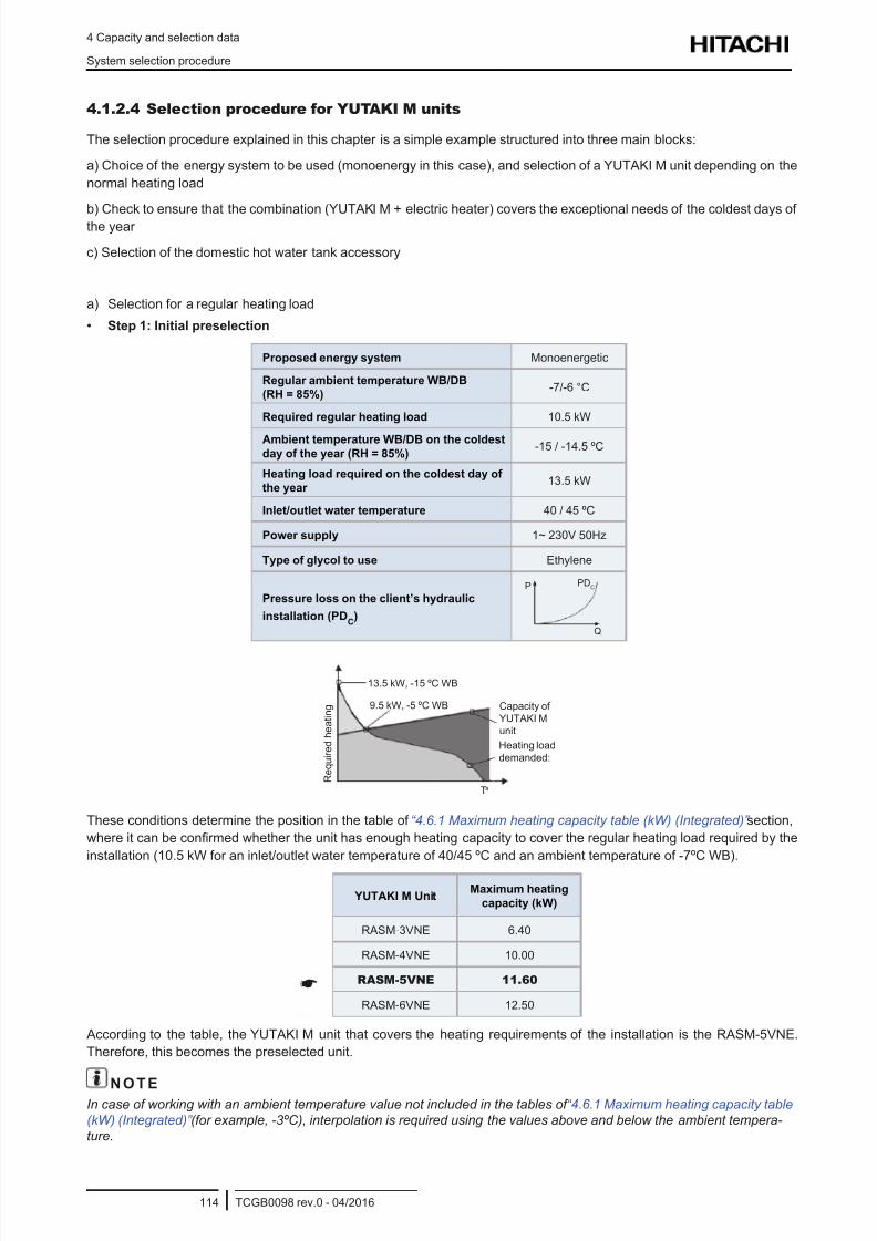
8/16/2019 Hitachi Yutaki Series 2016 Αντλίες θερμότητας
http://slidepdf.com/reader/full/hitachi-yutaki-series-2016- 124/256
4 Capacity and selection data
System selection procedure
TCGB0098 rev.0 - 04/2016114
4.1.2.4 Selection procedure for YUTAKI M units
The selection procedure explained in this chapter is a simple example structured into three main blocks:
a) Choice of the energy system to be used (monoenergy in this case), and selection of a YUTAKI M unit depending on the
normal heating load
b) Check to ensure that the combination (YUTAKI M + electric heater) covers the exceptional needs of the coldest days of
the year
c) Selection of the domestic hot water tank accessory
a) Selection for a regular heating load
• Step 1: Initial preselection
Proposed energy system Monoenergetic
Regular ambient temperature WB/DB
(RH = 85%)-7/-6 °C
Required regular heating load 10.5 kW
Ambient temperature WB/DB on the coldest
day of the year (RH = 85%)-15 / -14.5 ºC
Heating load required on the coldest day of
the year 13.5 kW
Inlet/outlet water temperature 40 / 45 ºC
Power supply 1~ 230V 50Hz
Type of glycol to use Ethylene
Pressure loss on the client’s hydraulic
installation (PDC)
P
Q
PDC
13.5 kW, -15 ºC WB
Capacity of
YUTAKI M
unit
R e q u i r e d h e a t i n g
Ta
9.5 kW, -5 ºC WB
Heating load
demanded:
These conditions determine the position in the table of “4.6.1 Maximum heating capacity table (kW) (Integrated)” section,
where it can be conrmed whether the unit has enough heating capacity to cover the regular heating load required by the
installation (10.5 kW for an inlet/outlet water temperature of 40/45 ºC and an ambient temperature of -7ºC WB).
YUTAKI M UnitMaximum heating
capacity (kW)
RASM-3VNE 6.40
RASM-4VNE 10.00
RASM-5VNE 11.60
RASM-6VNE 12.50
According to the table, the YUTAKI M unit that covers the heating requirements of the installation is the RASM-5VNE.
Therefore, this becomes the preselected unit.
N O T EIn case of working with an ambient temperature value not included in the tables of “4.6.1 Maximum heating capacity table
(kW) (Integrated)” (for example, -3ºC), interpolation is required using the values above and below the ambient tempera-
ture.
8/16/2019 Hitachi Yutaki Series 2016 Αντλίες θερμότητας
http://slidepdf.com/reader/full/hitachi-yutaki-series-2016- 125/256
4 Capacity and selection data
System selection procedure
TCGB0098 rev.0 - 04/2016115
4
• Step 2: Heating capacity correction for use of glycol
The actual heating capacity of the preselected unit must be calculated applying the necessary correction factors:
Qh= Q
Mh x f
gh
Qh: Actual heating capacity (kW)QMh
: Maximum heating capacity (kW)
f gh
: Capacity correction factor owing to use of glycol
The maximum heating capacity (QMh
) of the RHUE-5AVHN-HM unit is 11.60 kW.
- Calculation of f gh
:
The unit may be damaged by water freezing in the pipes during shutdown periods, under low ambient
temperatures in winter. An antifreeze mixture with glycol is used to prevent this.
On the other hand, the percentage of glycol used may affect the heating capacity of the unit.
To calculate the capacity correction factor due to the use of glycol, please refer to the “ “4.7.2 Correction
factor owing to use of glycol (only for YUTAKI M)” section, bearing in mind the type of glycol to be used. In
this example, ethylene is used.
The ambient temperature value of -4 ºC DB does not appear in the table. Therefore, the percentage of
ethylene glycol to be used corresponds to the immediately lower ambient temperature in the table. In this
case, it is -7 ºC.
At this ambient temperature, the necessary percentage of ethylene glycol is 20%, for which the corre-
sponding capacity correction factor owing to the use of ethylene glycol of 1.
- Calculation of Qh:
Once the correction factors to be applied have been determined, the formula for actual heating capacity of
the unit RHUE-5AVHN-HM can be applied:
Qh= 11.3 kW x 1 = 11.3 kW
The preselection of the RASM-5VNE unit is valid, since its actual heating capacity (11.3 kW) is greater than the heating
load required by the installation (10.5 kW).
N O T E
If the calculated actual heating capacity is lower than that provided by the preselected unit, the calculation must be done
again with the immediately higher unit. If there is no unit higher than the preselected one, some other system or the regular
use of an electric heater should be considered.
b) Selection for the coldest days of the year (use of the auxiliary electric heater)
The previous calculation shows that the RASM-5VNE unit provides a heating capacity of 13.3 kW (-7 ºC WB), which is
greater than the regular heating load necessary of 10.5 kW, but does not reach the peak heating load of 13.5 kW (-15 ºCWB) necessary on the coldest days of the year. The auxiliary electric heater is used in these cases.
The aim of this section is to check that the energy system chosen (combination of the YUTAKI M unit + auxiliary electric
heater) covers the temporary heating requirements for the coldest days of the year.
• Step 1: Initial preselection
As the ambient temperature is lowered to -15 ºC, the capacity tables in the “Maximum heating capacity table” section must
be consulted again to determine the maximum heating capacity that the RASM-5VNE unit can provide under these new
conditions.
The maximum heating capacity for an ambient temperature of -15 ºC WB and a water inlet/outlet temperature of 40/45 ºC
is 9.43 kW.
8/16/2019 Hitachi Yutaki Series 2016 Αντλίες θερμότητας
http://slidepdf.com/reader/full/hitachi-yutaki-series-2016- 126/256
4 Capacity and selection data
System selection procedure
TCGB0098 rev.0 - 04/2016116
• Step 2: Correction of the heating capacity owing to the use of glycol
The actual heating capacity of the selected unit for the coldest days of the year is calculated by applying correction factors
for defrosting and glycol, following the previously used method.
Qh= Q
Mh x f
gh
Qh: Actual heating capacity (kW)
QMh
: Maximum heating capacity (kW)
f d: Defrosting correction factor
f gh
: Capacity correction factor owing to use of glycol
- Calculation of f gh
:
The ambient temperature value of -14.5 ºC DB does not appear in the tables in “4.7.2 Correction factor
owing to use of glycol (only for YUTAKI M)” section. Therefore, the percentage of ethylene glycol to use
corresponds to the immediately lower ambient temperature in the table. In this case, it is -22 ºC.
At this ambient temperature, the necessary percentage of ethylene glycol is 40%, for which there is acorresponding capacity correction factor, owing to the use of ethylene glycol, of 0.99.
- Calculation of Qh:
Once the correction factors to be applied have been determined, the formula for actual heating capacity of
the RHUE-5AVHN-HM unit can be applied:
Qh= 9.43 kW x 0.99 = 9.33 kW
• Step 3: Calculation for the heating capacity of the combination (YUTAKI M unit + electric heater)
Once the corresponding correction factors are applied, the actual heating capacity provided by the RASM-5VNE unit is
9.33 kW. This heating capacity does not cover the required heating load for the coldest days (13.5 kW).
In these cases, the electric water heater supplied by HITACHI as an accessory (WEH-6E) is to provide the auxiliary capac-
ity required to cover exceptional heating needs.
The electric heater offered by HITACHI as an accessory provides a power of 6
kW, which must be added to the heating capacity provided by the preselected unit.
The result is:
Qh= 9.33 kW + 6kW = 15.33 kW
N O T E
The heating capacity resulting from the combination (YUTAKI M unit + electric heater) is higher than the heating demand
of 13.5 kW estimated in this example for the coldest days of the year, and so the preselection of the RHUE-5AVHN-HMunit is considered valid.
The resulting energy system is as follows:
11.33 kW, -7 ºC WB
Maximum
capacity of the
RHUE-5AVHN-HM
unit
Required
heating
capacity
Outdoor ambient temperature
Heating load
demanded
9.43 kW, -15 ºC WB
13.5 kW, -15 ºC WB
15.33 kW, -15 ºC WB
9.5 kW, -7 ºC WB
Capacity of RHUE-5AVHN-HM +
electric heater accessory (WEH-6E)
8/16/2019 Hitachi Yutaki Series 2016 Αντλίες θερμότητας
http://slidepdf.com/reader/full/hitachi-yutaki-series-2016- 127/256
4 Capacity and selection data
System selection procedure
TCGB0098 rev.0 - 04/2016117
4
c) Selection of the domestic hot water tank accessory
The domestic hot water tank accessory corresponding to the selected YUTAKI M system is either DHWT-200S-3.0H2E or
DHWT-300S-3.0H2E, depending on the water demand and the combination method. The daily water demand is estimated
with the following calculation formula for consumption:
Di(T)= D
i(60ºC) x (60-T
i / T-T
i )
Where:
Di (T): Water demand at T temperature
Di (60ºC): Domestic hot water demand at 60 ºC
T: Temperature of the domestic hot water tank
T I : Temperature of the inlet cold water
- Calculation of DI (60 ºC):
The standard consumption, expressed in daily litres per person and determined by technical installation
regulations of each country, is used to calculate the domestic hot water demand at 60 ºC, DI (60 ºC). This
quantity is then multiplied by the expected number of users in the installation. In the following example, the
domestic hot water demand at 60 ºC has been considered as 30 litres per person, in a detached housewith 4 residents (3 bedrooms).
- Calculation of T :
The temperature of the domestic how water tank is an estimation referred to the temperature of the
accumulated water inside the tank, prior to operation. The temperature is usually in the range between
45 ºC and 65 ºC. It has been considered as 45 ºC in this example.
- Calculation of T I :
The temperature of the inlet cold water refers to the temperature of the water being supplied to the tank.
This temperature is in the range between 10 ºC and 15 ºC. 12 ºC is used in this example to calculate an
approximate water demand.
- Example:
Di(T)= 120 x (60-12 / 45-12) = 174.6 litres/day
174.6 x 2(*) = 349.2 litres/day approximate demand of hot water
N O T E
(*) It is recommended to multiply the calculated consumption by two, in case that the installation is in a detached house.
This is done to ensure a steady supply of hot water. In the case of a multifamily installation, it is not necessary to increase
the forecast of hot water demand, given the lower simultaneity factor.
Therefore, a 300 litre tank is recommended when the system is a combination with RASM-4VNE or higher, in order to ensure
a longer supply of hot water and a better system performance. In case that the conditions of demand are lower than those
specications, a tank with a capacity 200 litres can be selected, depending on the demand conditions. A table with the
selection of domestic hot water (DHW) tanks recommended by HITACHI for the different existing combinations is shown
below:
YUTAKI M system Domestic hot water tank
RASM-3VNEDHWT-200S-3.0H2E
DHWT-300S-3.0H2E
RASM-4(V)NE
DHWT-300S-3.0H2ERASM-5(V)NE
RASM-6(V)NE
N O T E
• The YUTAKI S80 system is designed for combination with a HITACHI domestic hot water tank. In case that another tank
is being used in combination with a YUTAKI S80 system, HITACHI cannot guarantee the proper operation or reliability
of the system.
• This procedure for selection of a domestic hot water tank is merely illustrative; please refer to the applicable localregulations in order to ensure a proper water demand value.
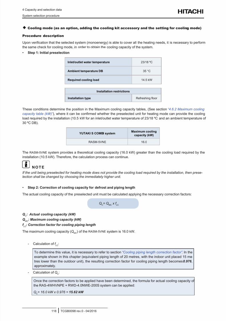
8/16/2019 Hitachi Yutaki Series 2016 Αντλίες θερμότητας
http://slidepdf.com/reader/full/hitachi-yutaki-series-2016- 128/256
4 Capacity and selection data
System selection procedure
TCGB0098 rev.0 - 04/2016118
Cooling mode (as an option, adding the cooling kit accessory and the setting for cooling mode)
Procedure description
Upon verication that the selected system (monoenergy) is able to cover all the heating needs, it is necessary to perform
the same check for cooling mode, in order to obtain the cooling capacity of the system.
• Step 1: Initial preselection
Inlet/outlet water temperature 23/18 ºC
Ambient temperature DB 35 °C
Required cooling load 14.5 kW
Installation restrictions
Installation type Refreshing oor
These conditions determine the position in the Maximum cooling capacity tables, (See section “4.6.2 Maximum cooling
capacity table (kW)” ), where it can be conrmed whether the preselected unit for heating mode can provide the cooling
load required by the installation (10.5 kW for an inlet/outlet water temperature of 23/18 ºC and an ambient temperature of
30 ºC DB).
YUTAKI S COMBI systemMaximum cooling
capacity (kW)
RASM-5VNE 16.0
The RASM-5VNE system provides a theoretical cooling capacity (16.0 kW) greater than the cooling load required by the
installation (10.5 kW). Therefore, the calculation process can continue.
N O T EIf the unit being preselected for heating mode does not provide the cooling load required by the installation, then prese-
lection shall be changed by choosing the immediately higher unit.
• Step 2: Correction of cooling capacity for defrost and piping length
The actual cooling capacity of the preselected unit must be calculated applying the necessary correction factors:
QC= Q
MC x f
LC
Q C : Actual cooling capacity (kW)
Q MC
: Maximum cooling capacity (kW)
f LC : Correction factor for cooling piping length
The maximum cooling capacity (QMC
) of the RASM-5VNE system is 16.0 kW.
- Calculation of f LC
:
To determine this value, it is necessary to refer to section “Cooling piping length correction factor” . In the
example shown in this chapter (equivalent piping length of 20 metres, with the indoor unit placed 15 me -
tres lower than the outdoor unit), the resulting correction factor for cooling piping length becomes 0.976 ,
approximately.
- Calculation of QC:
Once the correction factors to be applied have been determined, the formula for actual cooling capacity ofthe RAS-4WHVNPE + RWD-4.0NWE-200S system can be applied:
QC= 16.0 kW x 0.976 = 15.62 kW
8/16/2019 Hitachi Yutaki Series 2016 Αντλίες θερμότητας
http://slidepdf.com/reader/full/hitachi-yutaki-series-2016- 129/256
4 Capacity and selection data
System selection procedure
TCGB0098 rev.0 - 04/2016119
4
The actual cooling capacity of the RAS-4WHVNPE + RWD-4.0NWE-200S system (15.62 kW) is greater than the cooling
load required by the installation (14.5 kW). Therefore, the preselection is considered valid for both heating and cooling.
N O T E
If the calculated actual cooling capacity is lower than that provided by the preselected unit, the calculation must be done
again with the immediately higher unit.
4.1.3 Flow rate and pressure drop check
Step 1: Calculation of the ow rate required for the circulation pump
The following formula is used to calculate the required pumping ow in order to provide a heating capacity, producing an in-
crease in the difference of temperature between water inlet and water outlet, depending on the requested heating capacity.
CFR=Q
h x f
gf x 860
1000 x (T S- T
E )
CFR : Calculated ow rate (m3/h)
Qh: Actual heating capacity (kW)
f gf
: Correction factor of ow rate owing to use of glycol
(T S - T
E ): Difference in temperature between water inlet and water outlet (°C)
N O T E
Calculation of f gf : Once the actual heating capacity and the difference between the water inlet and water outlet tempera-
tures are known, the value required to calculate the pump ow rate is the ow correction factor due to the use of glycol fgf.
The use of glycol affects the actual heating capacity, since the density of glycol is higher than that of water. Therefore, a
higher ow rate is necessary for the same conditions. To calculate the ow rate correction factor owing to the use of glycol,
please see the table in section “4.7.2 Correction factor owing to use of glycol (only for YUTAKI M)” , bearing in mind the
type of glycol used.
• Step 2: Verication of the working limits of the ow on the water circulating pump
Once the ow needed for the pump has been determined, it must be veried whether is lies within the working limits of the
unit. Refer to the “6. Working range” chapter, where the maximum and minimum ow for each YUTAKI unit can be found.
• Step 3: Calculation of the necessary pressure to be provided by the circulating pump
The circulating pump must be able to provide the pressure required to make up for the pressure loss in the hydraulic unit
installation at the client’s side, working with the previously calculated ow.
The section “Pump performance curves” contains operation details of the YUTAKI models. The data needed are the
pressure losses from the hydraulic unit installation at the client’s side and have been estimated as given by the following
formula:
P = K x Q2
P = Loss of pressure on the client's hydraulic installation (mH2O)
Q = Pump ow rate of circulating water (m3/h)
K = Coefcient depending on the characteristics of the hydraulic
installation (diameter and length of pipes, roughness, etc.).
Check whether the selected units cover the pressure drop for the circulating ow rate in the “Pump performance curves”
section, and install an additional pump in the client’s hydraulic installation if necessary.
C A U T I O N
The use of glycol affect to the reading of some parameters like “water ow level” and “capacity” shown through the unit
controller menu. When glycol is used, these data are not correct and must be not used.
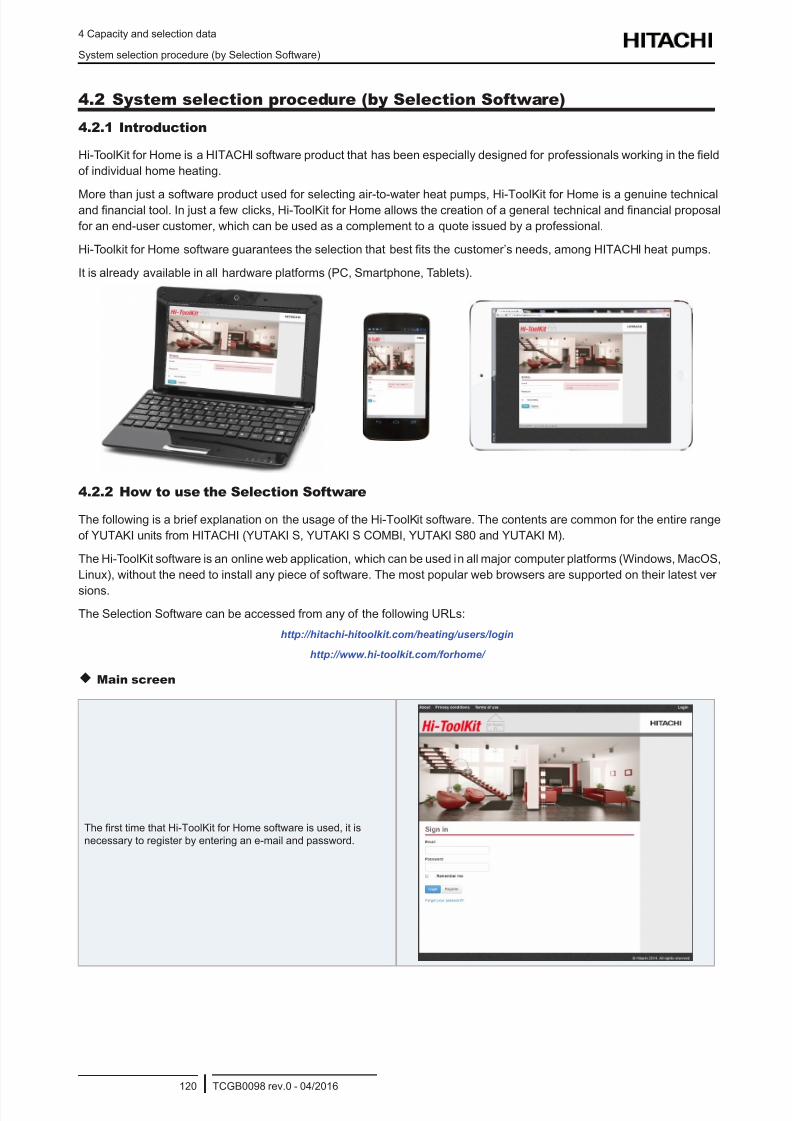
8/16/2019 Hitachi Yutaki Series 2016 Αντλίες θερμότητας
http://slidepdf.com/reader/full/hitachi-yutaki-series-2016- 130/256
4 Capacity and selection data
System selection procedure (by Selection Software)
TCGB0098 rev.0 - 04/2016120
4.2 System selection procedure (by Selection Software)
4.2.1 Introduction
Hi-ToolKit for Home is a HITACHI software product that has been especially designed for professionals working in the eld
of individual home heating.
More than just a software product used for selecting air-to-water heat pumps, Hi-ToolKit for Home is a genuine technicaland nancial tool. In just a few clicks, Hi-ToolKit for Home allows the creation of a general technical and nancial proposal
for an end-user customer, which can be used as a complement to a quote issued by a professional.
Hi-Toolkit for Home software guarantees the selection that best ts the customer’s needs, among HITACHI heat pumps.
It is already available in all hardware platforms (PC, Smartphone, Tablets).
4.2.2 How to use the Selection Software
The following is a brief explanation on the usage of the Hi-ToolKit software. The contents are common for the entire range
of YUTAKI units from HITACHI (YUTAKI S, YUTAKI S COMBI, YUTAKI S80 and YUTAKI M).
The Hi-ToolKit software is an online web application, which can be used in all major computer platforms (Windows, MacOS,
Linux), without the need to install any piece of software. The most popular web browsers are supported on their latest ver -
sions.
The Selection Software can be accessed from any of the following URLs:
http://hitachi-hitoolkit.com/heating/users/login
http://www.hi-toolkit.com/forhome/
Main screen
The rst time that Hi-ToolKit for Home software is used, it is
necessary to register by entering an e-mail and password.
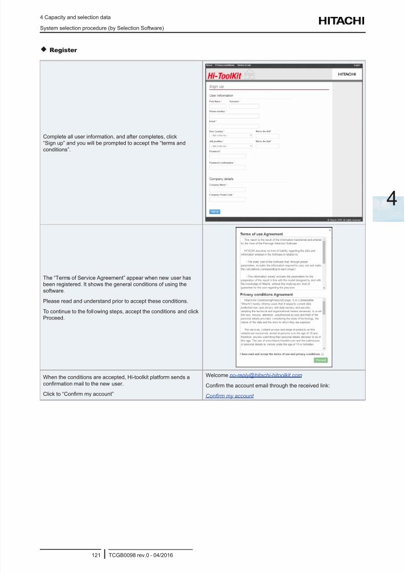
8/16/2019 Hitachi Yutaki Series 2016 Αντλίες θερμότητας
http://slidepdf.com/reader/full/hitachi-yutaki-series-2016- 131/256
4 Capacity and selection data
System selection procedure (by Selection Software)
TCGB0098 rev.0 - 04/2016121
4
Register
Complete all user information, and after completes, click
“Sign up” and you will be prompted to accept the “terms and
conditions”.
The “Terms of Service Agreement” appear when new user has
been registered. It shows the general conditions of using the
software.
Please read and understand prior to accept these conditions.
To continue to the following steps, accept the conditions and click
Proceed.
When the conditions are accepted, Hi-toolkit platform sends a
conrmation mail to the new user.
Click to “Conrm my account”
Welcome [email protected]
Conrm the account email through the received link:
Conrm my account
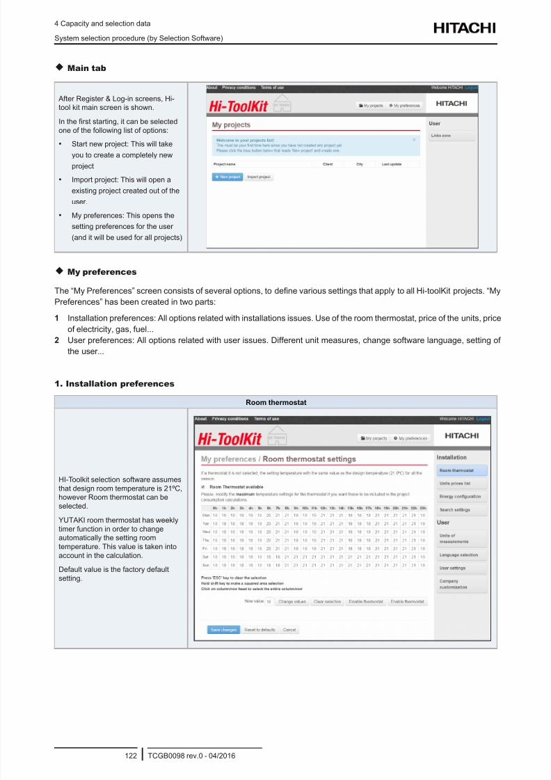
8/16/2019 Hitachi Yutaki Series 2016 Αντλίες θερμότητας
http://slidepdf.com/reader/full/hitachi-yutaki-series-2016- 132/256
4 Capacity and selection data
System selection procedure (by Selection Software)
TCGB0098 rev.0 - 04/2016122
Main tab
After Register & Log-in screens, Hi-
tool kit main screen is shown.
In the rst starting, it can be selected
one of the following list of options:
• Start new project: This will take
you to create a completely new
project
• Import project: This will open a
existing project created out of the
user.
• My preferences: This opens the
setting preferences for the user
(and it will be used for all projects)
My preferences
The “My Preferences” screen consists of several options, to dene various settings that apply to all Hi-toolKit projects. “My
Preferences” has been created in two parts:
1 Installation preferences: All options related with installations issues. Use of the room thermostat, price of the units, price
of electricity, gas, fuel...
2 User preferences: All options related with user issues. Different unit measures, change software language, setting of
the user...
1. Installation preferences
Room thermostat
HI-Toolkit selection software assumes
that design room temperature is 21ºC,
however Room thermostat can be
selected.
YUTAKI room thermostat has weekly
timer function in order to change
automatically the setting room
temperature. This value is taken intoaccount in the calculation.
Default value is the factory default
setting.
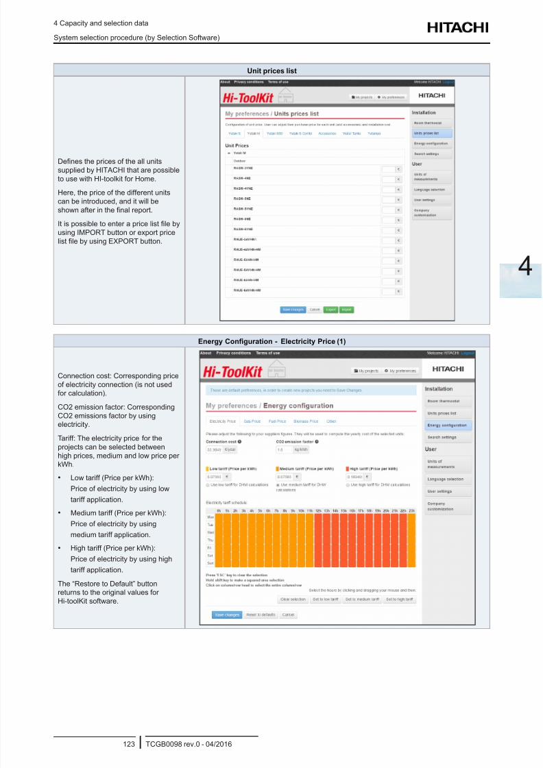
8/16/2019 Hitachi Yutaki Series 2016 Αντλίες θερμότητας
http://slidepdf.com/reader/full/hitachi-yutaki-series-2016- 133/256
4 Capacity and selection data
System selection procedure (by Selection Software)
TCGB0098 rev.0 - 04/2016123
4
Unit prices list
Denes the prices of the all units
supplied by HITACHI that are possible
to use with HI-toolkit for Home.
Here, the price of the different units
can be introduced, and it will be
shown after in the nal report.
It is possible to enter a price list le by
using IMPORT button or export price
list le by using EXPORT button.
Energy Conguration - Electricity Price (1)
Connection cost: Corresponding price
of electricity connection (is not used
for calculation).
CO2 emission factor: Corresponding
CO2 emissions factor by using
electricity.
Tariff: The electricity price for the
projects can be selected between
high prices, medium and low price per
kWh.
• Low tariff (Price per kWh):
Price of electricity by using low
tariff application.
• Medium tariff (Price per kWh):
Price of electricity by using
medium tariff application.• High tariff (Price per kWh):
Price of electricity by using high
tariff application.
The “Restore to Default” button
returns to the original values for
Hi-toolKit software.
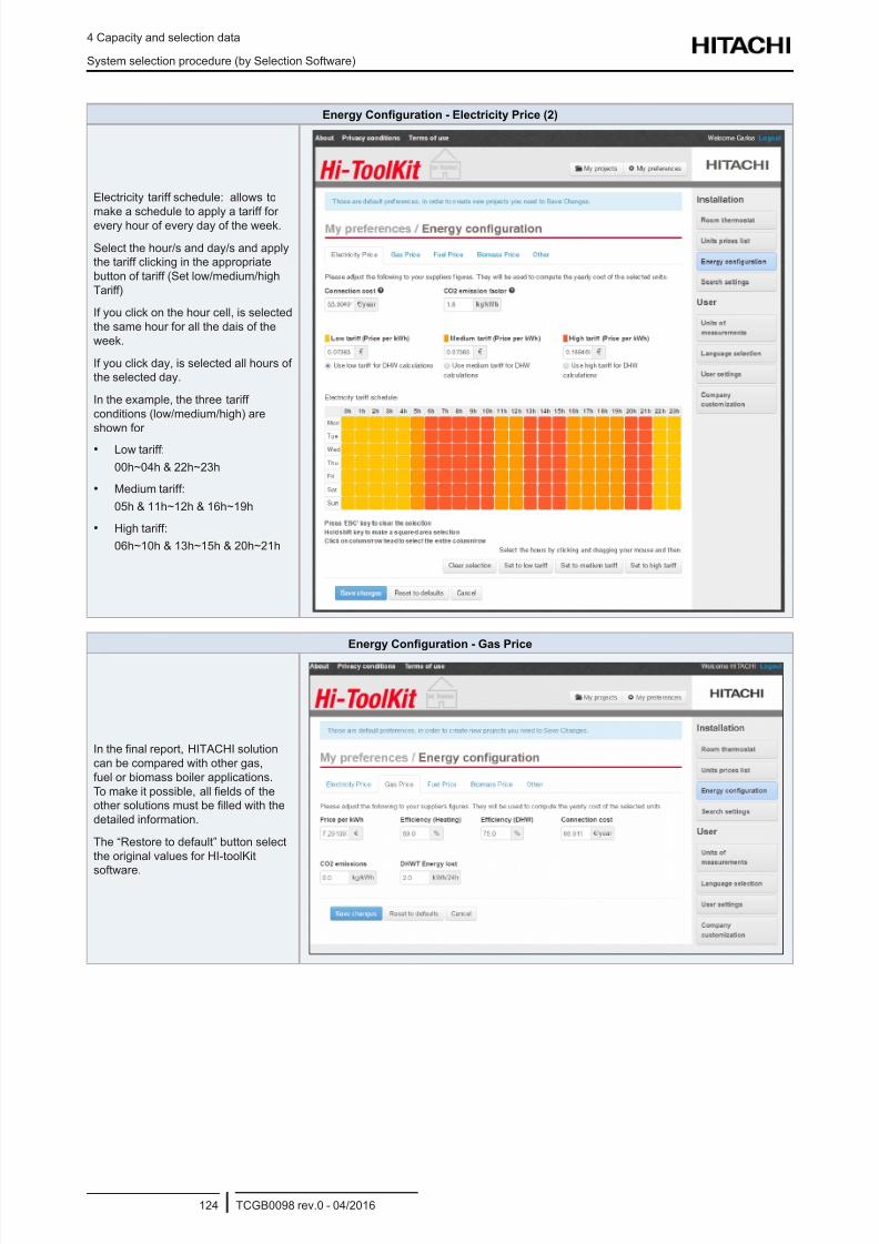
8/16/2019 Hitachi Yutaki Series 2016 Αντλίες θερμότητας
http://slidepdf.com/reader/full/hitachi-yutaki-series-2016- 134/256
4 Capacity and selection data
System selection procedure (by Selection Software)
TCGB0098 rev.0 - 04/2016124
Energy Conguration - Electricity Price (2)
Electricity tariff schedule: allows to
make a schedule to apply a tariff for
every hour of every day of the week.
Select the hour/s and day/s and apply
the tariff clicking in the appropriate
button of tariff (Set low/medium/high
Tariff)
If you click on the hour cell, is selected
the same hour for all the dais of the
week.
If you click day, is selected all hours of
the selected day.
In the example, the three tariff
conditions (low/medium/high) are
shown for
• Low tariff:
00h~04h & 22h~23h
• Medium tariff:
05h & 11h~12h & 16h~19h
• High tariff:
06h~10h & 13h~15h & 20h~21h
Energy Conguration - Gas Price
In the nal report, HITACHI solution
can be compared with other gas,
fuel or biomass boiler applications.
To make it possible, all elds of the
other solutions must be lled with the
detailed information.
The “Restore to default” button select
the original values for HI-toolKit
software.
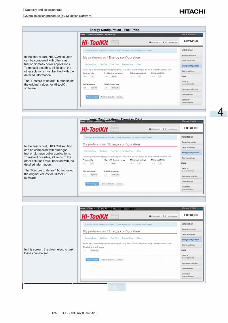
8/16/2019 Hitachi Yutaki Series 2016 Αντλίες θερμότητας
http://slidepdf.com/reader/full/hitachi-yutaki-series-2016- 135/256
4 Capacity and selection data
System selection procedure (by Selection Software)
TCGB0098 rev.0 - 04/2016125
4
Energy Conguration - Fuel Price
In the nal report, HITACHI solutioncan be compared with other gas,
fuel or biomass boiler applications.
To make it possible, all elds of the
other solutions must be lled with the
detailed information.
The “Restore to default” button select
the original values for HI-toolKit
software.
Energy Conguration - Biomass Price
In the nal report, HITACHI solution
can be compared with other gas,
fuel or biomass boiler applications.
To make it possible, all elds of the
other solutions must be lled with the
detailed information.
The “Restore to default” button selectthe original values for HI-toolKit
software.
Energy Conguration - Other
In this screen; the direct electric tank
losses can be set.
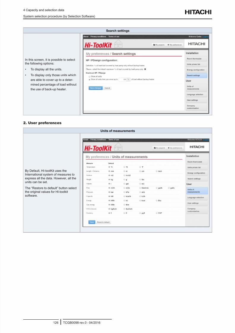
8/16/2019 Hitachi Yutaki Series 2016 Αντλίες θερμότητας
http://slidepdf.com/reader/full/hitachi-yutaki-series-2016- 136/256
4 Capacity and selection data
System selection procedure (by Selection Software)
TCGB0098 rev.0 - 04/2016126
Search settings
In this screen, it is possible to select
the following options:
• To display all the units.
• To display only those units which
are able to cover up to a deter-
mined percentage of load without
the use of back-up heater.
2. User preferences
Units of measurements
By Default, HI-toolKit uses the
International system of measures toexpress all the data. However, all the
units can be set.
The “Restore to default” button select
the original values for HI-toolkit
software.
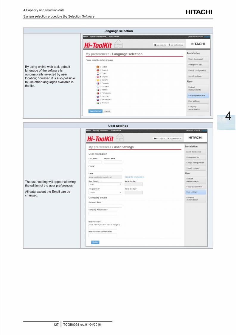
8/16/2019 Hitachi Yutaki Series 2016 Αντλίες θερμότητας
http://slidepdf.com/reader/full/hitachi-yutaki-series-2016- 137/256
4 Capacity and selection data
System selection procedure (by Selection Software)
TCGB0098 rev.0 - 04/2016127
4
Language selection
By using online web tool, default
language of the software is
automatically selected by user
location; however, it is also possible
to use other languages available in
the list.
User settings
The user setting will appear allowing
the edition of the user preferences.
All data except the Email can be
changed.
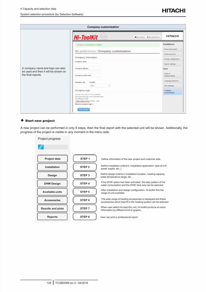
8/16/2019 Hitachi Yutaki Series 2016 Αντλίες θερμότητας
http://slidepdf.com/reader/full/hitachi-yutaki-series-2016- 138/256
4 Capacity and selection data
System selection procedure (by Selection Software)
TCGB0098 rev.0 - 04/2016128
Company customization
A company name and logo can also
be used and then it will be shown on
the nal reports.
Start new project
A new project can be performed in only 8 steps, then the nal report with the selected unit will be shown. Additionally, the
progress of the project is visible in any moment in the menu side.
After installation and design conguration, Hi-toolkit nd the
range of unit available.
The wide range of heating accessories is displayed and these
accessories which best t in the heating system can be selected
STEP 7
STEP 8Reports
Results and plots
STEP 1 Dene information of the new project and customer side.
Dene installation criteria’s, installation application, type of unit,
power supply, etc..)
Dene design criteria’s: Installation location, heating capacity,
water temperature range, etc….
If the DHW option has been activated, the daily pattern of hot
water consumption and the DHW tank size can be selected
User can print a professional report
When user select his best the unit, Hi-toolkit produce an extra
information by different kind of graphs..
STEP 2
STEP 3
STEP 4
STEP 5
STEP 6
Project data
Installation
Design
DHW Design
Available units
Accessories
Project progress
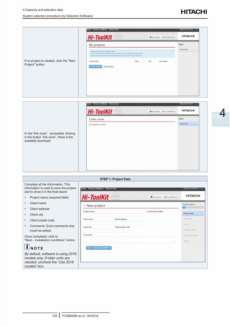
8/16/2019 Hitachi Yutaki Series 2016 Αντλίες θερμότητας
http://slidepdf.com/reader/full/hitachi-yutaki-series-2016- 139/256
4 Capacity and selection data
System selection procedure (by Selection Software)
TCGB0098 rev.0 - 04/2016129
4
If no project is created, click the “New
Project” button.
In the “link zone”, accessible clicking
in the button “link zone”, there is the
available download
STEP 1: Project Data
Complete all the information. This
information is used to save the project
and to show it in the nal report.
• Project name (required eld)
• Client name
• Client address
• Client city
• Client postal code
• Comments: Extra comments that
could be added.
Once completed, click to
“Next – Installation conditions” button.
N O T E
By default, software is using 2016
models only. If older units areneeded, uncheck the “Use 2016
models” box.
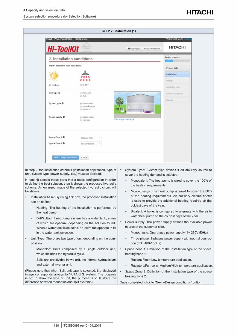
8/16/2019 Hitachi Yutaki Series 2016 Αντλίες θερμότητας
http://slidepdf.com/reader/full/hitachi-yutaki-series-2016- 140/256
4 Capacity and selection data
System selection procedure (by Selection Software)
TCGB0098 rev.0 - 04/2016130
STEP 2: Installation (1)
In step 2, the installation criteria’s (installation application, type of
unit, system type, power supply, etc.) must be decided.
HI-tool kit selects those parts into a basic conguration in order
to dene the best solution, then it shows the proposed hydraulic
scheme. An enlarged image of the selected hydraulic circuit will
be shown.
• Installation base: By using tick box, the proposed installation
can be dened.
- Heating: The heating of the installation is performed by
the heat pump.
- DHW: Each heat pump system has a water tank, some
of which are optional, depending on the solution found.
When a water tank is selected, an extra tab appears to ll
in the water tank selection.
• Unit Type: There are two type of unit depending on the com-
position:
- Monobloc: Units composed by a single outdoor unit,
which includes the hydraulic cycle.
- Split unit are divided in two unit, the internal hydraulic unit
and external inverter unit.
(Please note that when Split unit type is selected, the displayed
image corresponds always to YUTAKI S system. The purpose
is not to show the type of unit, the purpose is to illustrate the
difference between monobloc and split systems).
• System Type: System type denes if an auxiliary source to
cover the heating demand is selected.
- Monovalent: The heat pump is sized to cover the 100% of
the heating requirements.
- Mono-Energy: The heat pump is sized to cover the 80%
of the heating requirements. An auxiliary electric heater
is used to provide the additional heating required on the
coldest days of the year.
- Bivalent: A boiler is congured to alternate with the air to
water heat pump on the coldest days of the year.
• Power supply: The power supply denes the available power
source at the customer side.
- Monophasic: One-phase power supply (1~ 230V 50Hz)
- Three-phase: 3-phases power supply with neutral connec-
tion (3N~ 400V 50Hz)
• Space Zone 1: Denition of the installation type of the space
heating zone 1.
- Radiant Floor: Low temperature application.
- Radiators/Fan coils: Medium/High temperature application.
• Space Zone 2: Denition of the installation type of the space
heating zone 2.
Once completed, click to “Next –Design conditions ” button.
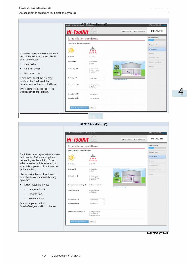
8/16/2019 Hitachi Yutaki Series 2016 Αντλίες θερμότητας
http://slidepdf.com/reader/full/hitachi-yutaki-series-2016- 141/256
4 Capacity and selection data
System selection procedure (by Selection Software)
TCGB0098 rev.0 - 04/2016131
4
STEP 2: Installation (2)
If System type selected is Bivalent,
one of the following types of boiler
shall be selected:
• Gas Boiler
• Oil Fuel Boiler
• Biomass boiler
Remember to set the “Energy
conguration” in Installation
preferences for the selected boiler.
Once completed, click to “Next –
Design conditions” button.
STEP 2: Installation (3)
Each heat pump system has a water
tank, some of which are optional,
depending on the solution found.
When a water tank is selected, an
extra tab appears to ll in the water
tank selection.
The following types of tank are
available to combine with heating
systems:
• DHW installation type:
- Integrated tank
- External tank
- Yutempo tank
Once completed, click to
“Next –Design conditions” button.
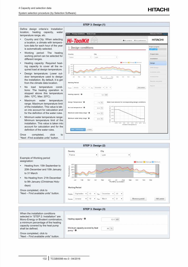
8/16/2019 Hitachi Yutaki Series 2016 Αντλίες θερμότητας
http://slidepdf.com/reader/full/hitachi-yutaki-series-2016- 142/256
4 Capacity and selection data
System selection procedure (by Selection Software)
TCGB0098 rev.0 - 04/2016132
STEP 3: Design (1)
Dene design criteria’s: Installation
location, heating capacity, water
temperature range, etc.
• Country and City: When selecting
a location, a climate with tempera-
ture data for each hour of the yearis automatically selected.
• Working period: The heating
working period can be selected for
different ranges.
• Heating capacity: Required heat-
ing capacity to cover all the re-
quired load at design temperature.
• Design temperature: Lower out-
door temperature used to design
the installation. By default, it is get
from the climate data location.
• No load temperature condi-
tions: The heating operation is
stopped above this temperature(Min: 12ºC, Max: 20ºC).
• Maximum water temperature
range: Maximum temperature limit
of the installation. This value is tak-
en into account for calculation and
for the denition of the water rules.
• Minimum water temperature range:
Minimum temperature limit of the
installation. This value is taken into
account for calculation and for the
denition of the water rules.
Once completed, click to
“Next –Find available units” button.
STEP 3: Design (2)
Example of Working period
assignation:
• Heating from: 15th September to
20th December and 10th January
to 31 March
• No Heating from: 21th December
to 9th January (Christmas Holy-
days)
Once completed, click to
“Next – Find available units” button.
STEP 3: Design (3)
When the installation conditions
selected in “STEP 2: Installation” are
Mono-Energy or Bivalent combination,
a minimum percentage of the heating
capacity covered by the heat pump
shall be dened.
Once completed, click to“Next – Find available units” button.
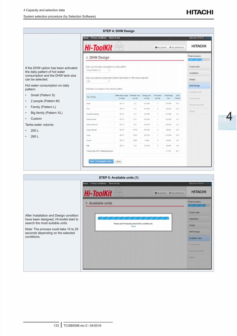
8/16/2019 Hitachi Yutaki Series 2016 Αντλίες θερμότητας
http://slidepdf.com/reader/full/hitachi-yutaki-series-2016- 143/256
4 Capacity and selection data
System selection procedure (by Selection Software)
TCGB0098 rev.0 - 04/2016133
4
STEP 4: DHW Design
If the DHW option has been activated
the daily pattern of hot water
consumption and the DHW tank size
can be selected.
Hot water consumption on daily
pattern:
• Small (Pattern S)
• 2 people (Pattern M)
• Family (Pattern L)
• Big family (Pattern XL)
• Custom
Tanks water volume:
• 200 L
• 260 L
STEP 5: Available units (1)
After Installation and Design condition
have been designed, HI-toolkit start to
search the most suitable units.
Note: The process could take 10 to 20
seconds depending on the selected
conditions.
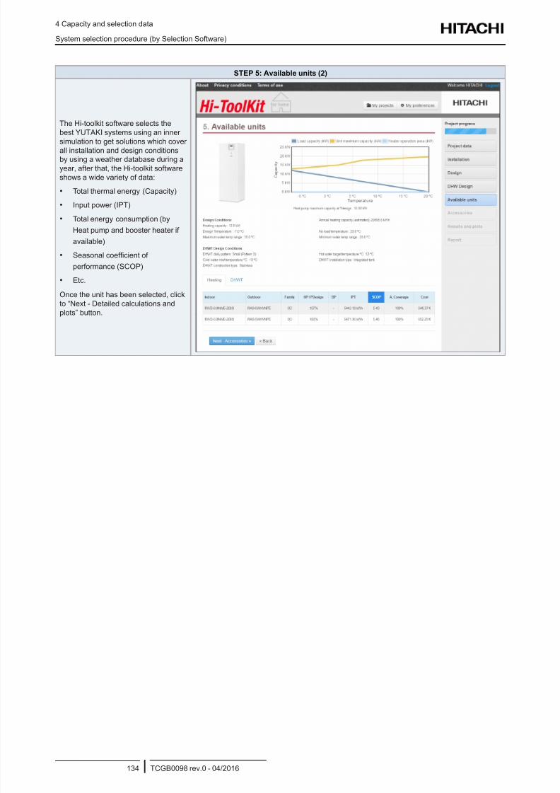
8/16/2019 Hitachi Yutaki Series 2016 Αντλίες θερμότητας
http://slidepdf.com/reader/full/hitachi-yutaki-series-2016- 144/256
4 Capacity and selection data
System selection procedure (by Selection Software)
TCGB0098 rev.0 - 04/2016134
STEP 5: Available units (2)
The Hi-toolkit software selects the
best YUTAKI systems using an inner
simulation to get solutions which coverall installation and design conditions
by using a weather database during a
year, after that, the Hi-toolkit software
shows a wide variety of data:
• Total thermal energy (Capacity)
• Input power (IPT)
• Total energy consumption (by
Heat pump and booster heater if
available)
• Seasonal coefcient of
performance (SCOP)
• Etc.
Once the unit has been selected, click
to “Next - Detailed calculations and
plots” button.
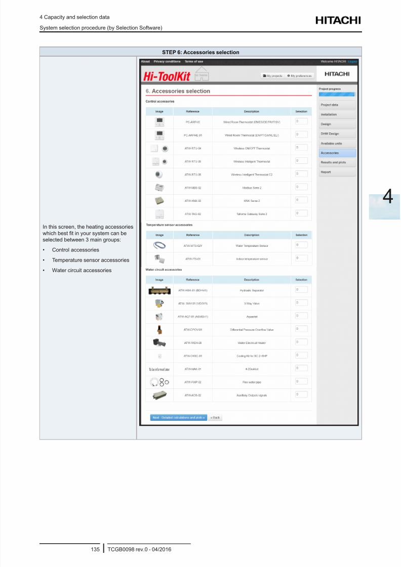
8/16/2019 Hitachi Yutaki Series 2016 Αντλίες θερμότητας
http://slidepdf.com/reader/full/hitachi-yutaki-series-2016- 145/256
4 Capacity and selection data
System selection procedure (by Selection Software)
TCGB0098 rev.0 - 04/2016135
4
STEP 6: Accessories selection
In this screen, the heating accessories
which best t in your system can be
selected between 3 main groups:
• Control accessories
• Temperature sensor accessories
• Water circuit accessories
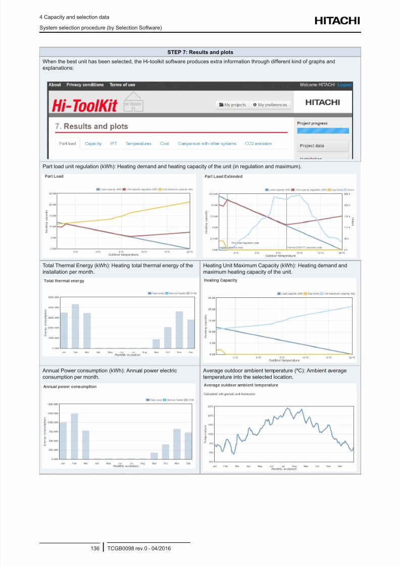
8/16/2019 Hitachi Yutaki Series 2016 Αντλίες θερμότητας
http://slidepdf.com/reader/full/hitachi-yutaki-series-2016- 146/256
4 Capacity and selection data
System selection procedure (by Selection Software)
TCGB0098 rev.0 - 04/2016136
STEP 7: Results and plots
When the best unit has been selected, the Hi-toolkit software produces extra information through different kind of graphs and
explanations:
Part load unit regulation (kWh): Heating demand and heating capacity of the unit (in regulation and maximum).
Total Thermal Energy (kWh): Heating total thermal energy of the
installation per month.
Heating Unit Maximum Capacity (kWh): Heating demand and
maximum heating capacity of the unit.
Annual Power consumption (kWh): Annual power electric
consumption per month.
Average outdoor ambient temperature (ºC): Ambient average
temperature into the selected location.
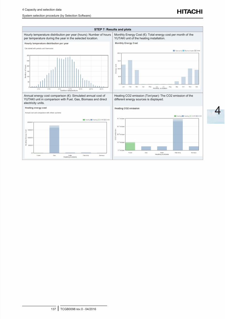
8/16/2019 Hitachi Yutaki Series 2016 Αντλίες θερμότητας
http://slidepdf.com/reader/full/hitachi-yutaki-series-2016- 147/256
4 Capacity and selection data
System selection procedure (by Selection Software)
TCGB0098 rev.0 - 04/2016137
4
STEP 7: Results and plots
Hourly temperature distribution per year (hours): Number of hours
per temperature during the year in the selected location.
Monthly Energy Cost (€): Total energy cost per month of the
YUTAKI unit of the heating installation.
Annual energy cost comparison (€): Simulated annual cost of
YUTAKI unit in comparison with Fuel, Gas, Biomass and direct
electricity units.
Heating CO2 emission (Ton/year): The CO2 emission of the
different energy sources is displayed.
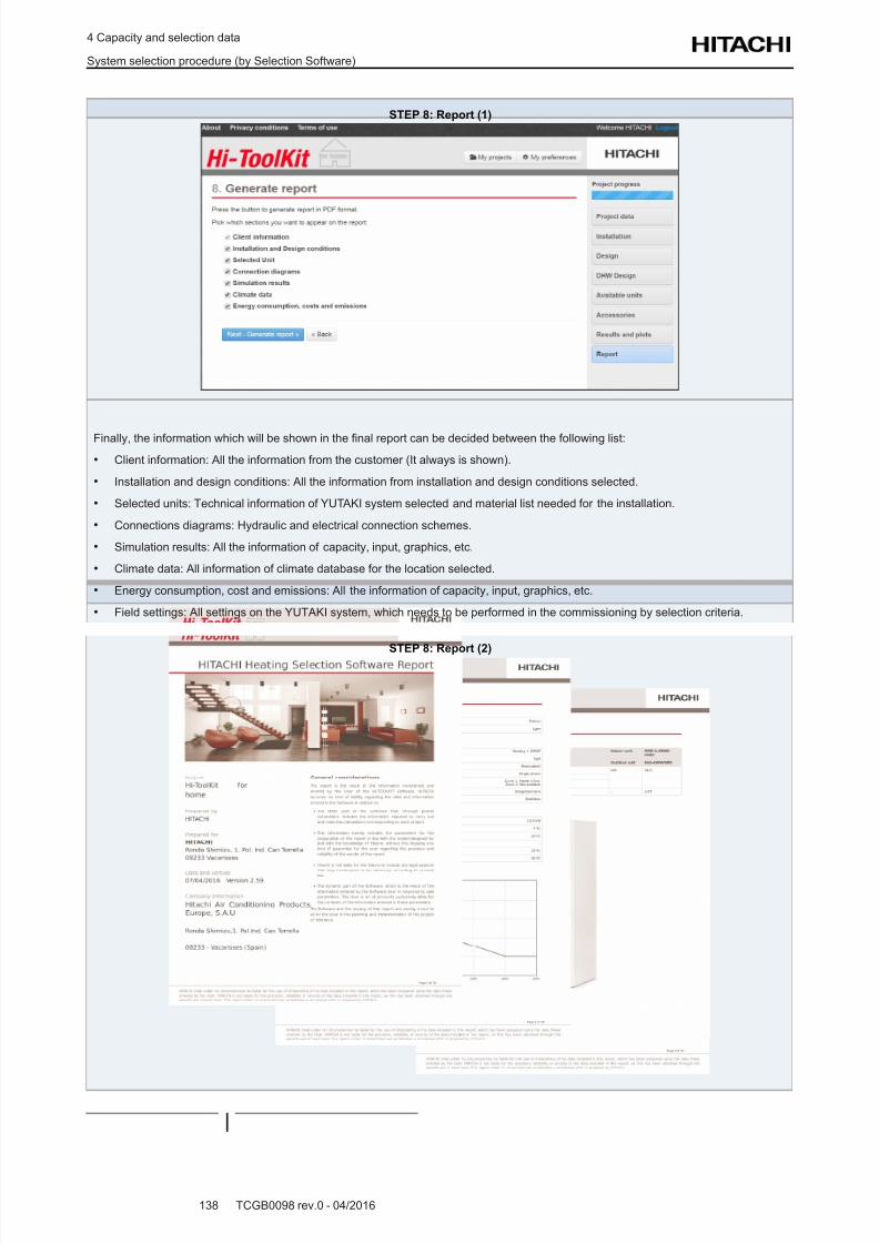
8/16/2019 Hitachi Yutaki Series 2016 Αντλίες θερμότητας
http://slidepdf.com/reader/full/hitachi-yutaki-series-2016- 148/256
4 Capacity and selection data
System selection procedure (by Selection Software)
TCGB0098 rev.0 - 04/2016138
STEP 8: Report (1)
Finally, the information which will be shown in the nal report can be decided between the following list:
• Client information: All the information from the customer (It always is shown).
• Installation and design conditions: All the information from installation and design conditions selected.
• Selected units: Technical information of YUTAKI system selected and material list needed for the installation.
• Connections diagrams: Hydraulic and electrical connection schemes.
• Simulation results: All the information of capacity, input, graphics, etc.
• Climate data: All information of climate database for the location selected.
• Energy consumption, cost and emissions: All the information of capacity, input, graphics, etc.
• Field settings: All settings on the YUTAKI system, which needs to be performed in the commissioning by selection criteria.
STEP 8: Report (2)
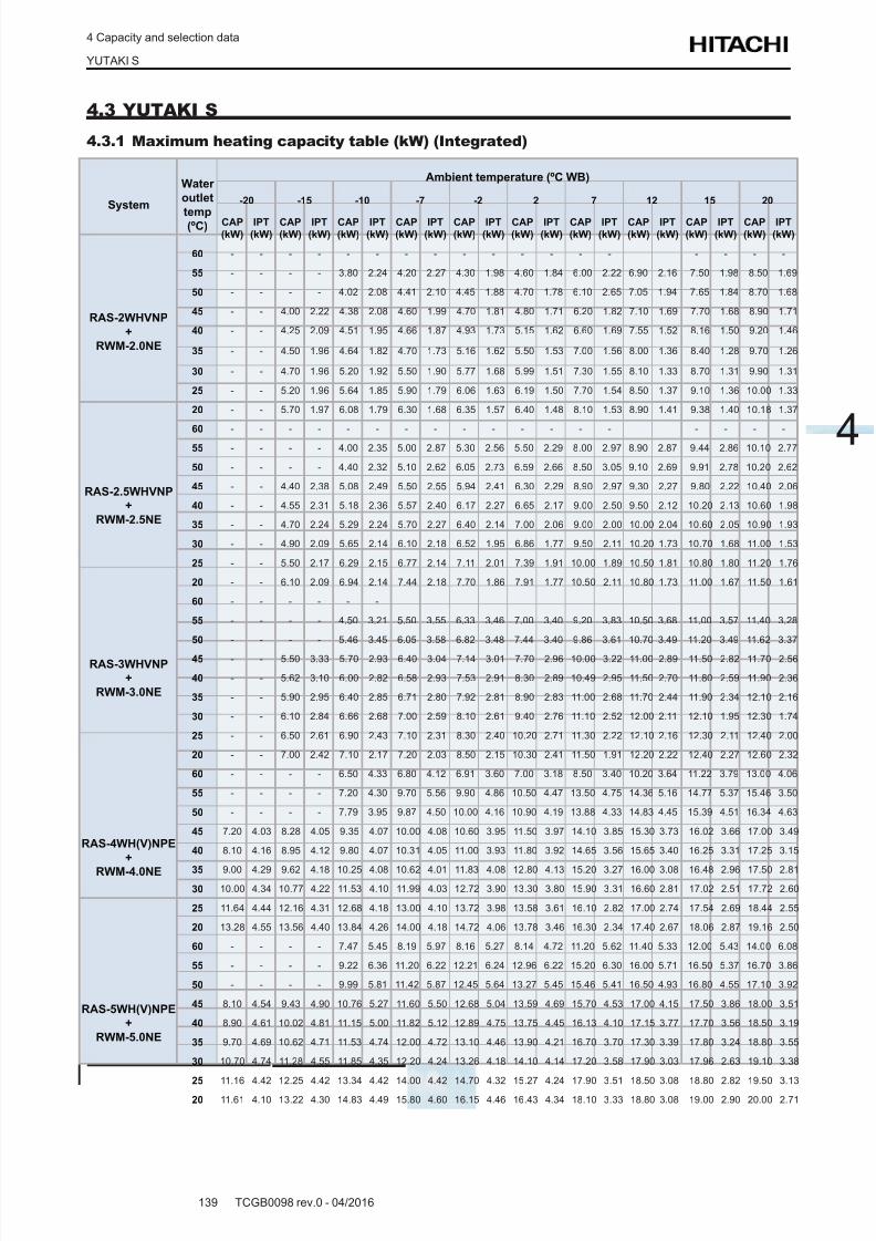
8/16/2019 Hitachi Yutaki Series 2016 Αντλίες θερμότητας
http://slidepdf.com/reader/full/hitachi-yutaki-series-2016- 149/256
4 Capacity and selection data
YUTAKI S
TCGB0098 rev.0 - 04/2016139
4
4.3 YUTAKI S
4.3.1 Maximum heating capacity table (kW) (Integrated)
System
Water
outlet
temp(ºC)
Ambient temperature (ºC WB)
-20 -15 -10 -7 -2 2 7 12 15 20
CAP
(kW)
IPT
(kW)
CAP
(kW)
IPT
(kW)
CAP
(kW)
IPT
(kW)
CAP
(kW)
IPT
(kW)
CAP
(kW)
IPT
(kW)
CAP
(kW)
IPT
(kW)
CAP
(kW)
IPT
(kW)
CAP
(kW)
IPT
(kW)
CAP
(kW)
IPT
(kW)
CAP
(kW)
IPT
(kW)
RAS-2WHVNP
+
RWM-2.0NE
60 - - - - - - - - - - - - - - - - - -
55 - - - - 3.80 2.24 4.20 2.27 4.30 1.98 4.60 1.84 6.00 2.22 6.90 2.16 7.50 1.98 8.50 1.69
50 - - - - 4.02 2.08 4.41 2.10 4.45 1.88 4.70 1.78 6.10 2.65 7.05 1.94 7.65 1.84 8.70 1.68
45 - - 4.00 2.22 4.38 2.08 4.60 1.99 4.70 1.81 4.80 1.71 6.20 1.82 7.10 1.69 7.70 1.68 8.90 1.71
40 - - 4.25 2.09 4.51 1.95 4.66 1.87 4.93 1.73 5.15 1.62 6.60 1.69 7.55 1.52 8.16 1.50 9.20 1.46
35 - - 4.50 1.96 4.64 1.82 4.70 1.73 5.16 1.62 5.50 1.53 7.00 1.56 8.00 1.36 8.40 1.28 9.70 1.26
30 - - 4.70 1.96 5.20 1.92 5.50 1.90 5.77 1.68 5.99 1.51 7.30 1.55 8.10 1.33 8.70 1.31 9.90 1.31
25 - - 5.20 1.96 5.64 1.85 5.90 1.79 6.06 1.63 6.19 1.50 7.70 1.54 8.50 1.37 9.10 1.36 10.00 1.33
20 - - 5.70 1.97 6.08 1.79 6.30 1.68 6.35 1.57 6.40 1.48 8.10 1.53 8.90 1.41 9.38 1.40 10.18 1.37
RAS-2.5WHVNP
+
RWM-2.5NE
60 - - - - - - - - - - - - - - - - - -
55 - - - - 4.00 2.35 5.00 2.87 5.30 2.56 5.50 2.29 8.00 2.97 8.90 2.87 9.44 2.86 10.10 2.77
50 - - - - 4.40 2.32 5.10 2.62 6.05 2.73 6.59 2.66 8.50 3.05 9.10 2.69 9.91 2.78 10.20 2.62
45 - - 4.40 2.38 5.08 2.49 5.50 2.55 5.94 2.41 6.30 2.29 8.90 2.97 9.30 2.27 9.80 2.22 10.40 2.06
40 - - 4.55 2.31 5.18 2.36 5.57 2.40 6.17 2.27 6.65 2.17 9.00 2.50 9.50 2.12 10.20 2.13 10.60 1.98
35 - - 4.70 2.24 5.29 2.24 5.70 2.27 6.40 2.14 7.00 2.06 9.00 2.00 10.00 2.04 10.60 2.05 10.90 1.93
30 - - 4.90 2.09 5.65 2.14 6.10 2.18 6.52 1.95 6.86 1.77 9.50 2.11 10.20 1.73 10.70 1.68 11.00 1.53
25 - - 5.50 2.17 6.29 2.15 6.77 2.14 7.11 2.01 7.39 1.91 10.00 1.89 10.50 1.81 10.80 1.80 11.20 1.76
20 - - 6.10 2.09 6.94 2.14 7.44 2.18 7.70 1.86 7.91 1.77 10.50 2.11 10.80 1.73 11.00 1.67 11.50 1.61
RAS-3WHVNP
+
RWM-3.0NE
60 - - - - - -
55 - - - - 4.50 3.21 5.50 3.55 6.33 3.46 7.00 3.40 9.20 3.83 10.50 3.68 11.00 3.57 11.40 3.28
50 - - - - 5.46 3.45 6.05 3.58 6.82 3.48 7.44 3.40 9.86 3.61 10.70 3.49 11.20 3.49 11.62 3.37
45 - - 5.50 3.33 5.70 2.93 6.40 3.04 7.14 3.01 7.70 2.96 10.00 3.22 11.00 2.89 11.50 2.82 11.70 2.56
40 - - 5.62 3.10 6.00 2.82 6.58 2.93 7.53 2.91 8.30 2.89 10.49 2.95 11.50 2.70 11.80 2.59 11.90 2.36
35 - - 5.90 2.95 6.40 2.85 6.71 2.80 7.92 2.81 8.90 2.83 11.00 2.68 11.70 2.44 11.90 2.34 12.10 2.16
30 - - 6.10 2.84 6.66 2.68 7.00 2.59 8.10 2.61 9.40 2.76 11.10 2.52 12.00 2.11 12.10 1.95 12.30 1.74
25 - - 6.50 2.61 6.90 2.43 7.10 2.31 8.30 2.40 10.20 2.71 11.30 2.22 12.10 2.16 12.30 2.11 12.40 2.00
20 - - 7.00 2.42 7.10 2.17 7.20 2.03 8.50 2.15 10.30 2.41 11.50 1.91 12.20 2.22 12.40 2.27 12.60 2.32
RAS-4WH(V)NPE
+
RWM-4.0NE
60 - - - - 6.50 4.33 6.80 4.12 6.91 3.60 7.00 3.18 8.50 3.40 10.20 3.64 11.22 3.79 13.00 4.06
55 - - - - 7.20 4.30 9.70 5.56 9.90 4.86 10.50 4.47 13.50 4.75 14.36 5.16 14.77 5.37 15.46 3.50
50 - - - - 7.79 3.95 9.87 4.50 10.00 4.16 10.90 4.19 13.88 4.33 14.83 4.45 15.39 4.51 16.34 4.63
45 7.20 4.03 8.28 4.05 9.35 4.07 10.00 4.08 10.60 3.95 11.50 3.97 14.10 3.85 15.30 3.73 16.02 3.66 17.00 3.49
40 8.10 4.16 8.95 4.12 9.80 4.07 10.31 4.05 11.00 3.93 11.80 3.92 14.65 3.56 15.65 3.40 16.25 3.31 17.25 3.15
35 9.00 4.29 9.62 4.18 10.25 4.08 10.62 4.01 11.83 4.08 12.80 4.13 15.20 3.27 16.00 3.08 16.48 2.96 17.50 2.81
30 10.00 4.34 10.77 4.22 11.53 4.10 11.99 4.03 12.72 3.90 13.30 3.80 15.90 3.31 16.60 2.81 17.02 2.51 17.72 2.60
25 11.64 4.44 12.16 4.31 12.68 4.18 13.00 4.10 13.72 3.98 13.58 3.61 16.10 2.82 17.00 2.74 17.54 2.69 18.44 2.55
20 13.28 4.55 13.56 4.40 13.84 4.26 14.00 4.18 14.72 4.06 13.78 3.46 16.30 2.34 17.40 2.67 18.06 2.87 19.16 2.50
RAS-5WH(V)NPE
+
RWM-5.0NE
60 - - - - 7.47 5.45 8.19 5.97 8.16 5.27 8.14 4.72 11.20 5.62 11.40 5.33 12.00 5.43 14.00 6.08
55 - - - - 9.22 6.36 11.20 6.22 12.21 6.24 12.96 6.22 15.20 6.30 16.00 5.71 16.50 5.37 16.70 3.86
50 - - - - 9.99 5.81 11.42 5.87 12.45 5.64 13.27 5.45 15.46 5.41 16.50 4.93 16.80 4.55 17.10 3.92
45 8.10 4.54 9.43 4.90 10.76 5.27 11.60 5.50 12.68 5.04 13.59 4.69 15.70 4.53 17.00 4.15 17.50 3.86 18.00 3.51
40 8.90 4.61 10.02 4.81 11.15 5.00 11.82 5.12 12.89 4.75 13.75 4.45 16.13 4.10 17.15 3.77 17.70 3.56 18.50 3.19
35 9.70 4.69 10.62 4.71 11.53 4.74 12.00 4.72 13.10 4.46 13.90 4.21 16.70 3.70 17.30 3.39 17.80 3.24 18.80 3.55
30 10.70 4.74 11.28 4.55 11.85 4.35 12.20 4.24 13.26 4.18 14.10 4.14 17.20 3.58 17.90 3.03 17.96 2.63 19.10 3.38
25 11.16 4.42 12.25 4.42 13.34 4.42 14.00 4.42 14.70 4.32 15.27 4.24 17.90 3.51 18.50 3.08 18.80 2.82 19.50 3.13
20 11.61 4.10 13.22 4.30 14.83 4.49 15.80 4.60 16.15 4.46 16.43 4.34 18.10 3.33 18.80 3.08 19.00 2.90 20.00 2.71
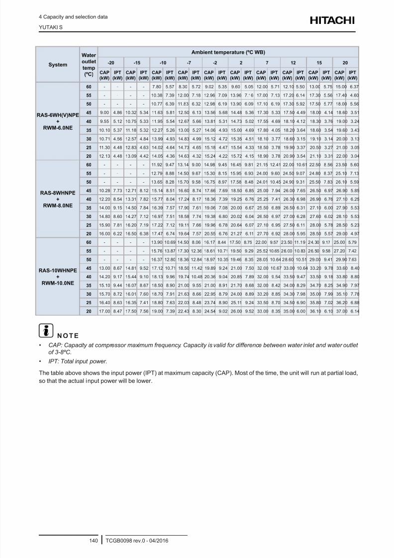
8/16/2019 Hitachi Yutaki Series 2016 Αντλίες θερμότητας
http://slidepdf.com/reader/full/hitachi-yutaki-series-2016- 150/256
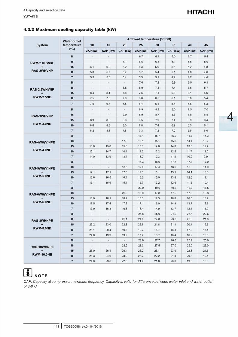
8/16/2019 Hitachi Yutaki Series 2016 Αντλίες θερμότητας
http://slidepdf.com/reader/full/hitachi-yutaki-series-2016- 151/256
4 Capacity and selection data
YUTAKI S
TCGB0098 rev.0 - 04/2016141
4
4.3.2 Maximum cooling capacity table (kW)
System
Water outlet
temperature
(ºC)
Ambient temperature (°C DB)
10 15 20 25 30 35 40 45
CAP (kW) CAP (kW) CAP (kW) CAP (kW) CAP (kW) CAP (kW) CAP (kW) CAP (kW)
RWM-2.0FSN3E
+
RAS-2WHVNP
20 - - 6.7 6.4 6.0 5.7 5.4
18 - - 7.1 6.6 6.3 6.1 5.6 5.0
15 6.1 6.2 6.2 6.3 5.9 5.5 5.2 4.8
10 5.8 5.7 5.7 5.7 5.4 5.1 4.8 4.6
7 5.5 5.6 5.4 5.3 5.1 4.9 4.7 4.4
RAS-2.5WHVNP
+
RWM-2.5NE
20 - - - 7.6 7.2 6.9 6.5 6.1
18 - - 8.5 8.0 7.8 7.4 6.6 5.7
15 8.4 8.1 7.8 7.6 7.1 6.6 6.1 5.6
10 7.5 7.3 7.0 6.8 6.5 6.1 5.8 5.4
7 7.0 6.8 6.5 6.4 6.1 5.8 5.6 5.3
RAS-3WHVNP
+
RWM-3.0NE
20 - - - 8.9 8.4 8.0 7.5 7.0
18 - - 9.0 8.9 8.7 8.5 7.5 6.5
15 8.9 8.8 8.6 8.5 7.9 7.4 6.9 6.4
10 8.6 8.3 8.0 7.8 7.4 6.9 6.5 6.1
7 8.2 8.1 7.8 7.3 7.2 7.0 6.5 6.0
RAS-4WH(V)NPE
+
RWM-4.0NE
20 - - - 16.1 15.7 15.2 14.8 14.3
18 - - 17.0 16.1 15.1 15.0 14.4 13.7
15 16.0 15.8 15.5 15.3 14.6 14.0 13.3 12.7
10 15.1 14.7 14.4 14.0 13.2 12.5 11.7 11.0
7 14.0 13.9 13.4 13.2 12.3 11.8 10.9 9.9
RAS-5WH(V)NPE
+
RWM-5.0NE
20 - - - 18.3 18.0 17.7 17.3 17.0
18 - - 18.5 17.6 17.4 16.0 15.0 14.0
15 17.1 17.1 17.0 17.1 16.1 15.1 14.1 13.0
10 16.6 16.5 16.4 16.2 15.0 13.8 12.6 11.4
7 16.1 15.9 15.4 15.7 13.2 12.6 11.5 10.4
RAS-6WH(V)NPE
+
RWM-6.0NE
20 20.0 19.6 19.3 18.9 18.5
18 20.0 19.0 17.8 17.5 17.3 16.8
15 18.0 18.1 18.2 18.3 17.5 16.8 16.0 15.2
10 17.5 17.4 17.2 17.1 16.0 14.9 13.7 12.6
7 17.0 16.8 16.3 16.4 14.9 13.7 12.4 11.0
RAS-8WHNPE
+
RWM-8.0NE
20 - - - 25.8 25.0 24.2 23.4 22.6
18 - - 25.1 24.6 24.0 23.5 22.3 21.0
15 23.2 23.0 22.8 22.6 21.8 21.1 20.4 19.6
10 21.1 20.4 19.8 19.2 18.7 18.3 17.8 17.4
7 24.0 19.9 19.2 17.2 16.7 16.4 16.2 16.0
RAS-10WHNPE
+
RWM-10.0NE
20 - - - 28.6 27.7 26.8 25.9 25.0
18 - - 28.5 28.0 27.5 27.0 25.0 23.0
15 26.0 26.1 26.1 26.2 25.1 23.9 22.8 21.6
10 25.3 24.6 23.9 23.2 22.2 21.3 20.3 19.4
7 24.0 23.6 22.8 21.4 21.0 20.6 19.3 18.0
N O T E
CAP: Capacity at compressor maximum frequency. Capacity is valid for difference between water inlet and water outlet
of 3-8ºC.
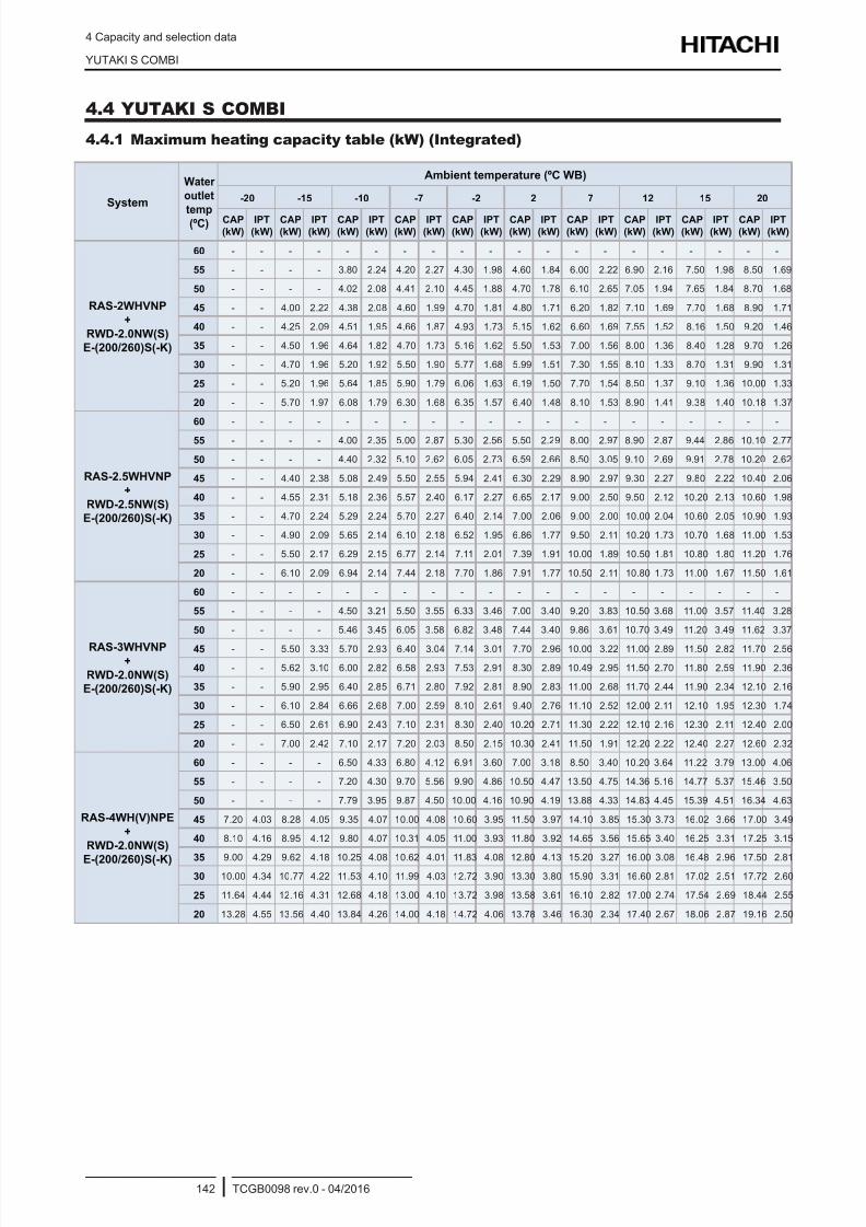
8/16/2019 Hitachi Yutaki Series 2016 Αντλίες θερμότητας
http://slidepdf.com/reader/full/hitachi-yutaki-series-2016- 152/256
4 Capacity and selection data
YUTAKI S COMBI
TCGB0098 rev.0 - 04/2016142
4.4 YUTAKI S COMBI
4.4.1 Maximum heating capacity table (kW) (Integrated)
System
Water
outlet
temp(ºC)
Ambient temperature (ºC WB)
-20 -15 -10 -7 -2 2 7 12 15 20
CAP
(kW)
IPT
(kW)
CAP
(kW)
IPT
(kW)
CAP
(kW)
IPT
(kW)
CAP
(kW)
IPT
(kW)
CAP
(kW)
IPT
(kW)
CAP
(kW)
IPT
(kW)
CAP
(kW)
IPT
(kW)
CAP
(kW)
IPT
(kW)
CAP
(kW)
IPT
(kW)
CAP
(kW)
IPT
(kW)
RAS-2WHVNP
+
RWD-2.0NW(S)
E-(200/260)S(-K)
60 - - - - - - - - - - - - - - - - - - - -
55 - - - - 3.80 2.24 4.20 2.27 4.30 1.98 4.60 1.84 6.00 2.22 6.90 2.16 7.50 1.98 8.50 1.69
50 - - - - 4.02 2.08 4.41 2.10 4.45 1.88 4.70 1.78 6.10 2.65 7.05 1.94 7.65 1.84 8.70 1.68
45 - - 4.00 2.22 4.38 2.08 4.60 1.99 4.70 1.81 4.80 1.71 6.20 1.82 7.10 1.69 7.70 1.68 8.90 1.71
40 - - 4.25 2.09 4.51 1.95 4.66 1.87 4.93 1.73 5.15 1.62 6.60 1.69 7.55 1.52 8.16 1.50 9.20 1.46
35 - - 4.50 1.96 4.64 1.82 4.70 1.73 5.16 1.62 5.50 1.53 7.00 1.56 8.00 1.36 8.40 1.28 9.70 1.26
30 - - 4.70 1.96 5.20 1.92 5.50 1.90 5.77 1.68 5.99 1.51 7.30 1.55 8.10 1.33 8.70 1.31 9.90 1.31
25 - - 5.20 1.96 5.64 1.85 5.90 1.79 6.06 1.63 6.19 1.50 7.70 1.54 8.50 1.37 9.10 1.36 10.00 1.33
20 - - 5.70 1.97 6.08 1.79 6.30 1.68 6.35 1.57 6.40 1.48 8.10 1.53 8.90 1.41 9.38 1.40 10.18 1.37
RAS-2.5WHVNP
+
RWD-2.5NW(S)
E-(200/260)S(-K)
60 - - - - - - - - - - - - - - - - - - - -
55 - - - - 4.00 2.35 5.00 2.87 5.30 2.56 5.50 2.29 8.00 2.97 8.90 2.87 9.44 2.86 10.10 2.77
50 - - - - 4.40 2.32 5.10 2.62 6.05 2.73 6.59 2.66 8.50 3.05 9.10 2.69 9.91 2.78 10.20 2.62
45 - - 4.40 2.38 5.08 2.49 5.50 2.55 5.94 2.41 6.30 2.29 8.90 2.97 9.30 2.27 9.80 2.22 10.40 2.06
40 - - 4.55 2.31 5.18 2.36 5.57 2.40 6.17 2.27 6.65 2.17 9.00 2.50 9.50 2.12 10.20 2.13 10.60 1.98
35 - - 4.70 2.24 5.29 2.24 5.70 2.27 6.40 2.14 7.00 2.06 9.00 2.00 10.00 2.04 10.60 2.05 10.90 1.93
30 - - 4.90 2.09 5.65 2.14 6.10 2.18 6.52 1.95 6.86 1.77 9.50 2.11 10.20 1.73 10.70 1.68 11.00 1.53
25 - - 5.50 2.17 6.29 2.15 6.77 2.14 7.11 2.01 7.39 1.91 10.00 1.89 10.50 1.81 10.80 1.80 11.20 1.76
20 - - 6.10 2.09 6.94 2.14 7.44 2.18 7.70 1.86 7.91 1.77 10.50 2.11 10.80 1.73 11.00 1.67 11.50 1.61
RAS-3WHVNP+
RWD-2.0NW(S)
E-(200/260)S(-K)
60 - - - - - - - - - - - - - - - - - - - -
55 - - - - 4.50 3.21 5.50 3.55 6.33 3.46 7.00 3.40 9.20 3.83 10.50 3.68 11.00 3.57 11.40 3.28
50 - - - - 5.46 3.45 6.05 3.58 6.82 3.48 7.44 3.40 9.86 3.61 10.70 3.49 11.20 3.49 11.62 3.37
45 - - 5.50 3.33 5.70 2.93 6.40 3.04 7.14 3.01 7.70 2.96 10.00 3.22 11.00 2.89 11.50 2.82 11.70 2.56
40 - - 5.62 3.10 6.00 2.82 6.58 2.93 7.53 2.91 8.30 2.89 10.49 2.95 11.50 2.70 11.80 2.59 11.90 2.36
35 - - 5.90 2.95 6.40 2.85 6.71 2.80 7.92 2.81 8.90 2.83 11.00 2.68 11.70 2.44 11.90 2.34 12.10 2.16
30 - - 6.10 2.84 6.66 2.68 7.00 2.59 8.10 2.61 9.40 2.76 11.10 2.52 12.00 2.11 12.10 1.95 12.30 1.74
25 - - 6.50 2.61 6.90 2.43 7.10 2.31 8.30 2.40 10.20 2.71 11.30 2.22 12.10 2.16 12.30 2.11 12.40 2.00
20 - - 7.00 2.42 7.10 2.17 7.20 2.03 8.50 2.15 10.30 2.41 11.50 1.91 12.20 2.22 12.40 2.27 12.60 2.32
RAS-4WH(V)NPE
+
RWD-2.0NW(S)
E-(200/260)S(-K)
60 - - - - 6.50 4.33 6.80 4.12 6.91 3.60 7.00 3.18 8.50 3.40 10.20 3.64 11.22 3.79 13.00 4.06
55 - - - - 7.20 4.30 9.70 5.56 9.90 4.86 10.50 4.47 13.50 4.75 14.36 5.16 14.77 5.37 15.46 3.50
50 - - - - 7.79 3.95 9.87 4.50 10.00 4.16 10.90 4.19 13.88 4.33 14.83 4.45 15.39 4.51 16.34 4.63
45 7.20 4.03 8.28 4.05 9.35 4.07 10.00 4.08 10.60 3.95 11.50 3.97 14.10 3.85 15.30 3.73 16.02 3.66 17.00 3.49
40 8.10 4.16 8.95 4.12 9.80 4.07 10.31 4.05 11.00 3.93 11.80 3.92 14.65 3.56 15.65 3.40 16.25 3.31 17.25 3.15
35 9.00 4.29 9.62 4.18 10.25 4.08 10.62 4.01 11.83 4.08 12.80 4.13 15.20 3.27 16.00 3.08 16.48 2.96 17.50 2.81
30 10.00 4.34 10.77 4.22 11.53 4.10 11.99 4.03 12.72 3.90 13.30 3.80 15.90 3.31 16.60 2.81 17.02 2.51 17.72 2.60
25 11.64 4.44 12.16 4.31 12.68 4.18 13.00 4.10 13.72 3.98 13.58 3.61 16.10 2.82 17.00 2.74 17.54 2.69 18.44 2.55
20 13.28 4.55 13.56 4.40 13.84 4.26 14.00 4.18 14.72 4.06 13.78 3.46 16.30 2.34 17.40 2.67 18.06 2.87 19.16 2.50
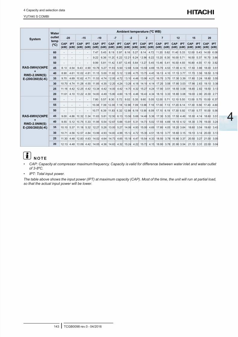
8/16/2019 Hitachi Yutaki Series 2016 Αντλίες θερμότητας
http://slidepdf.com/reader/full/hitachi-yutaki-series-2016- 153/256
4 Capacity and selection data
YUTAKI S COMBI
TCGB0098 rev.0 - 04/2016143
4
System
Water
outlet
temp
(ºC)
Ambient temperature (ºC WB)
-20 -15 -10 -7 -2 2 7 12 15 20
CAP
(kW)
IPT
(kW)
CAP
(kW)
IPT
(kW)
CAP
(kW)
IPT
(kW)
CAP
(kW)
IPT
(kW)
CAP
(kW)
IPT
(kW)
CAP
(kW)
IPT
(kW)
CAP
(kW)
IPT
(kW)
CAP
(kW)
IPT
(kW)
CAP
(kW)
IPT
(kW)
CAP
(kW)
IPT
(kW)
RAS-5WH(V)NPE
+
RWD-2.0NW(S)
E-(200/260)S(-K)
60 - - - - 7.47 5.45 8.19 5.97 8.16 5.27 8.14 4.72 11.20 5.62 11.40 5.33 12.00 5.43 14.00 6.08
55 - - - - 9.22 6.36 11.20 6.22 12.21 6.24 12.96 6.22 15.20 6.30 16.00 5.71 16.50 5.37 16.70 3.8650 - - - - 9.99 5.81 11.42 5.87 12.45 5.64 13.27 5.45 15.46 5.41 16.50 4.93 16.80 4.55 17.10 3.92
45 8.10 4.54 9.43 4.90 10.76 5.27 11.60 5.50 12.68 5.04 13.59 4.69 15.70 4.53 17.00 4.15 17.50 3.86 18.00 3.51
40 8.90 4.61 10.02 4.81 11.15 5.00 11.82 5.12 12.89 4.75 13.75 4.45 16.13 4.10 17.15 3.77 17.70 3.56 18.50 3.19
35 9.70 4.69 10.62 4.71 11.53 4.74 12.00 4.72 13.10 4.46 13.90 4.21 16.70 3.70 17.30 3.39 17.80 3.24 18.80 3.55
30 10.70 4.74 11.28 4.55 11.85 4.35 12.20 4.24 13.26 4.18 14.10 4.14 17.20 3.58 17.90 3.03 17.96 2.63 19.10 3.38
25 11.16 4.42 12.25 4.42 13.34 4.42 14.00 4.42 14.70 4.32 15.27 4.24 17.90 3.51 18.50 3.08 18.80 2.82 19.50 3.13
20 11.61 4.10 13.22 4.30 14.83 4.49 15.80 4.60 16.15 4.46 16.43 4.34 18.10 3.33 18.80 3.08 19.00 2.90 20.00 2.71
RAS-6WH(V)NPE
+
RWD-2.0NW(S)
E-(200/260)S(-K)
60 - - - - 7.80 5.57 8.30 5.72 9.02 5.35 9.60 5.05 12.00 5.71 12.10 5.50 13.00 5.75 15.00 6.37
55 - - - - 10.38 7.39 12.00 7.18 12.96 7.09 13.96 7.16 17.00 7.13 17.20 6.14 17.30 5.56 17.40 4.60
50 - - - - 10.77 6.39 11.83 6.32 12.98 6.19 13.90 6.09 17.10 6.19 17.30 5.92 17.50 5.77 18.00 5.56
45 9.00 4.86 10.32 5.34 11.63 5.81 12.50 6.13 13.56 5.68 14.48 5.36 17.30 5.33 17.50 4.49 18.00 4.14 18.60 3.51
40 9.55 5.12 10.75 5.33 11.95 5.54 12.67 5.66 13.81 5.31 14.73 5.02 17.55 4.69 18.10 4.12 18.30 3.76 19.00 3.24
35 10.10 5.37 11.18 5.32 12.27 5.26 13.00 5.27 14.06 4.93 15.00 4.69 17.80 4.05 18.20 3.64 18.60 3.54 19.60 3.43
30 10.71 4.56 12.57 4.84 13.99 4.93 14.83 4.99 15.12 4.72 15.35 4.51 18.10 3.77 18.60 3.15 19.10 3.14 20.00 3.13
25 11.30 4.48 12.83 4.63 14.02 4.64 14.73 4.65 15.18 4.47 15.54 4.33 18.50 3.78 19.90 3.37 20.50 3.27 21.00 3.05
20 12.13 4.48 13.09 4.42 14.05 4.36 14.63 4.32 15.24 4.22 15.72 4.15 18.90 3.78 20.90 3.54 21.10 3.31 22.00 3.04
N O T E
• CAP: Capacity at compressor maximum frequency. Capacity is valid for difference between water inlet and water outlet
of 3-8ºC.
• IPT: Total input power.
The table above shows the input power (IPT) at maximum capacity (CAP). Most of the time, the unit will run at partial load,
so that the actual input power will be lower.
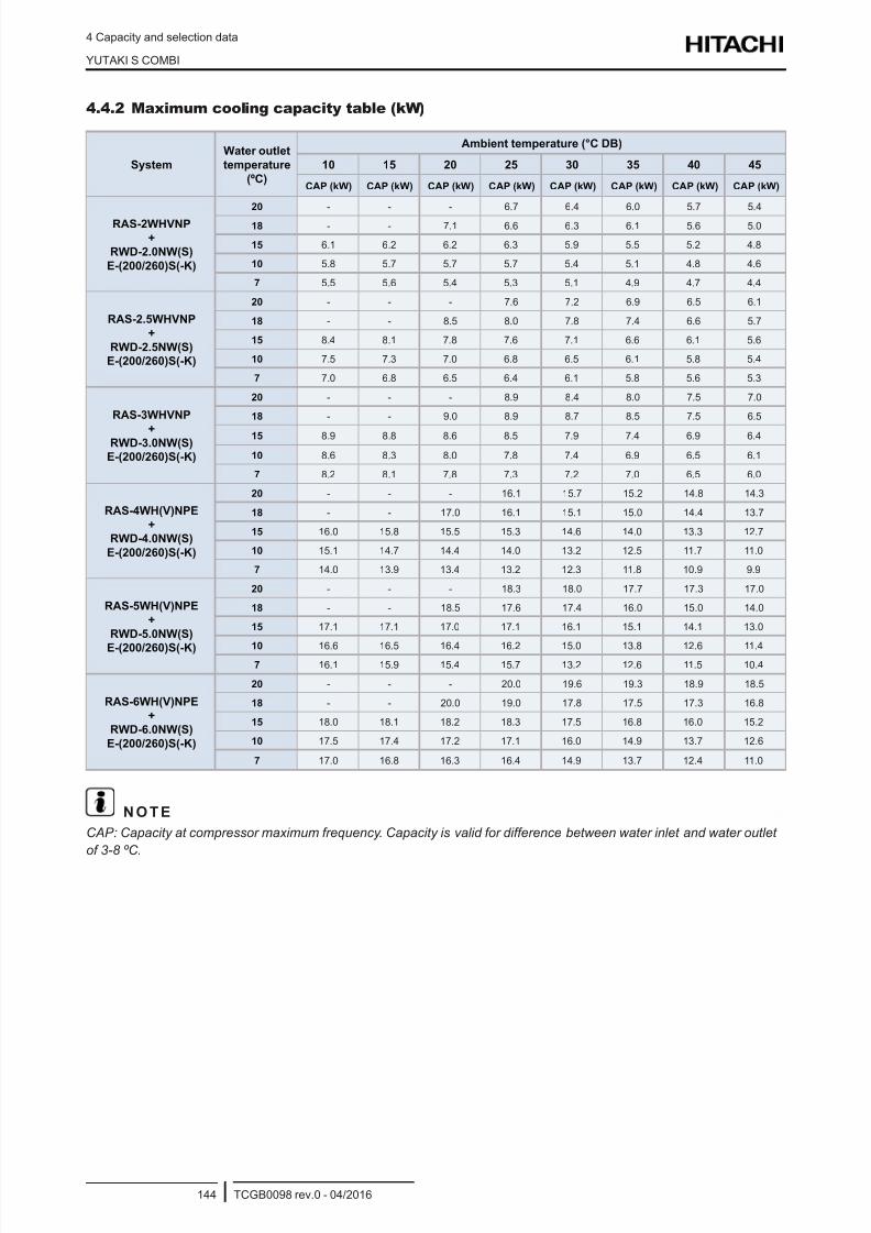
8/16/2019 Hitachi Yutaki Series 2016 Αντλίες θερμότητας
http://slidepdf.com/reader/full/hitachi-yutaki-series-2016- 154/256
4 Capacity and selection data
YUTAKI S COMBI
TCGB0098 rev.0 - 04/2016144
4.4.2 Maximum cooling capacity table (kW)
System
Water outlet
temperature
(ºC)
Ambient temperature (°C DB)
10 15 20 25 30 35 40 45
CAP (kW) CAP (kW) CAP (kW) CAP (kW) CAP (kW) CAP (kW) CAP (kW) CAP (kW)
RAS-2WHVNP
+
RWD-2.0NW(S)
E-(200/260)S(-K)
20 - - - 6.7 6.4 6.0 5.7 5.4
18 - - 7.1 6.6 6.3 6.1 5.6 5.0
15 6.1 6.2 6.2 6.3 5.9 5.5 5.2 4.8
10 5.8 5.7 5.7 5.7 5.4 5.1 4.8 4.6
7 5.5 5.6 5.4 5.3 5.1 4.9 4.7 4.4
RAS-2.5WHVNP
+
RWD-2.5NW(S)
E-(200/260)S(-K)
20 - - - 7.6 7.2 6.9 6.5 6.1
18 - - 8.5 8.0 7.8 7.4 6.6 5.7
15 8.4 8.1 7.8 7.6 7.1 6.6 6.1 5.6
10 7.5 7.3 7.0 6.8 6.5 6.1 5.8 5.4
7 7.0 6.8 6.5 6.4 6.1 5.8 5.6 5.3
RAS-3WHVNP
+RWD-3.0NW(S)
E-(200/260)S(-K)
20 - - - 8.9 8.4 8.0 7.5 7.0
18 - - 9.0 8.9 8.7 8.5 7.5 6.5
15 8.9 8.8 8.6 8.5 7.9 7.4 6.9 6.4
10 8.6 8.3 8.0 7.8 7.4 6.9 6.5 6.1
7 8.2 8.1 7.8 7.3 7.2 7.0 6.5 6.0
RAS-4WH(V)NPE
+
RWD-4.0NW(S)
E-(200/260)S(-K)
20 - - - 16.1 15.7 15.2 14.8 14.3
18 - - 17.0 16.1 15.1 15.0 14.4 13.7
15 16.0 15.8 15.5 15.3 14.6 14.0 13.3 12.7
10 15.1 14.7 14.4 14.0 13.2 12.5 11.7 11.0
7 14.0 13.9 13.4 13.2 12.3 11.8 10.9 9.9
RAS-5WH(V)NPE
+
RWD-5.0NW(S)
E-(200/260)S(-K)
20 - - - 18.3 18.0 17.7 17.3 17.0
18 - - 18.5 17.6 17.4 16.0 15.0 14.0
15 17.1 17.1 17.0 17.1 16.1 15.1 14.1 13.0
10 16.6 16.5 16.4 16.2 15.0 13.8 12.6 11.4
7 16.1 15.9 15.4 15.7 13.2 12.6 11.5 10.4
RAS-6WH(V)NPE
+
RWD-6.0NW(S)
E-(200/260)S(-K)
20 - - - 20.0 19.6 19.3 18.9 18.5
18 - - 20.0 19.0 17.8 17.5 17.3 16.8
15 18.0 18.1 18.2 18.3 17.5 16.8 16.0 15.2
10 17.5 17.4 17.2 17.1 16.0 14.9 13.7 12.6
7 17.0 16.8 16.3 16.4 14.9 13.7 12.4 11.0
N O T E
CAP: Capacity at compressor maximum frequency. Capacity is valid for difference between water inlet and water outlet
of 3-8 ºC.
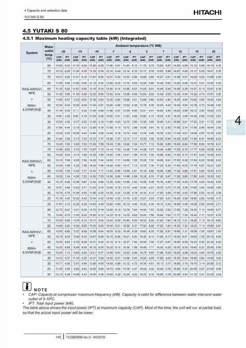
8/16/2019 Hitachi Yutaki Series 2016 Αντλίες θερμότητας
http://slidepdf.com/reader/full/hitachi-yutaki-series-2016- 155/256
4 Capacity and selection data
YUTAKI S 80
TCGB0098 rev.0 - 04/2016145
4
4.5 YUTAKI S 80
4.5.1 Maximum heating capacity table (kW) (Integrated)
System
Water
outlet
temp.
(ºC)
Ambient temperature (ºC WB)
-20 -15 -10 -7 -2 2 7 12 15 20
CAP
(kW)
IPT
(kW)
CAP
(kW)
IPT
(kW)
CAP
(kW)
IPT
(kW)
CAP
(kW)
IPT
(kW)
CAP
(kW)
IPT
(kW)
CAP
(kW)
IPT
(kW)
CAP
(kW)
IPT
(kW)
CAP
(kW)
IPT
(kW)
CAP
(kW)
IPT
(kW)
CAP
(kW)
IPT
(kW)
RAS-4WH(V)
NPE
+
RWH-
4.0VNF(W)E
80 10.60 6.42 11.10 6.50 10.80 6.28 11.90 6.61 11.84 6.12 11.79 5.73 13.50 5.87 14.50 5.69 15.10 5.58 16.10 5.39
75 10.73 6.26 11.26 6.35 11.23 6.29 12.10 6.49 12.14 6.10 12.17 5.78 13.83 5.89 14.67 5.68 15.17 5.55 16.01 5.35
70 10.91 6.05 11.47 6.16 11.81 6.30 12.37 6.33 12.54 6.06 12.68 5.85 14.27 5.91 14.89 5.67 15.26 5.52 15.88 5.28
65 11.00 5.95 11.58 6.06 12.10 6.30 12.50 6.25 12.74 6.05 12.94 5.89 14.49 5.92 15.00 5.66 15.31 5.51 15.82 5.25
60 11.15 5.92 11.67 6.00 12.16 6.15 12.50 6.14 12.90 6.07 13.22 6.01 14.49 5.46 15.00 5.25 15.31 5.13 15.81 4.38
55 11.30 5.89 11.76 5.94 12.22 6.00 12.50 6.04 13.06 6.09 13.64 6.55 14.49 5.00 15.00 4.84 15.30 4.74 15.81 3.50
50 11.90 6.07 12.22 6.02 12.39 5.93 12.50 5.84 12.98 5.61 13.66 5.80 14.50 4.84 15.20 4.84 15.62 4.84 16.32 4.84
45 12.50 6.25 12.50 6.03 12.50 5.81 12.50 5.68 13.02 5.38 13.78 5.49 14.50 4.53 15.30 4.64 15.78 4.70 16.58 4.80
40 11.14 5.59 11.11 5.24 11.09 4.89 11.08 4.67 12.08 4.69 12.51 4.41 14.85 3.90 15.65 3.86 16.13 3.83 16.93 3.79
35 9.00 4.29 9.62 4.18 10.25 4.08 10.62 4.01 11.83 4.08 12.80 4.13 15.20 3.27 16.00 3.08 16.48 2.96 17.50 2.81
30 10.00 4.34 10.77 4.22 11.53 4.10 11.99 4.03 12.72 3.90 13.30 3.80 15.90 3.31 16.60 2.81 17.02 2.51 17.72 2.60
25 11.64 4.44 12.16 4.31 12.68 4.18 13.00 4.10 13.72 3.98 13.58 3.61 16.10 2.82 17.00 2.74 17.54 2.69 18.44 2.55
20 13.28 4.55 13.56 4.40 13.84 4.26 14.00 4.18 14.72 4.06 13.78 3.46 16.30 2.34 17.40 2.67 18.06 2.87 19.16 2.50
RAS-5WH(V)
NPE
+
RWH-
5.0VNF(W)E
80 11.65 7.28 12.13 7.32 12.70 7.47 12.90 7.37 13.12 7.17 13.30 7.00 15.00 6.82 16.50 6.60 17.40 6.47 18.90 6.25
75 12.43 7.60 12.82 7.52 13.20 7.58 13.43 7.39 13.62 7.24 13.77 7.12 15.63 6.85 16.83 6.64 17.56 6.52 18.76 6.31
70 13.48 8.02 13.73 7.79 13.87 7.73 14.14 7.42 14.28 7.34 14.39 7.27 16.46 6.89 17.28 6.70 17.77 6.59 18.58 6.39
65 14.00 8.24 14.19 7.93 14.20 7.80 14.50 7.44 14.61 7.39 14.70 7.35 16.88 6.92 17.50 6.73 17.87 6.62 18.49 6.44
60 14.10 7.96 14.25 7.65 14.32 7.44 14.50 7.17 14.89 7.26 15.20 7.33 16.95 6.61 17.50 6.38 17.83 6.25 18.38 6.02
55 14.20 7.68 14.32 7.38 14.43 7.08 14.50 6.90 15.17 7.13 15.70 7.30 17.02 6.30 17.50 6.03 17.79 5.87 18.27 5.61
50 14.35 7.56 14.42 7.37 14.44 7.17 14.50 6.99 14.88 6.81 15.19 6.66 16.98 5.98 17.50 5.89 17.81 5.84 18.33 5.75
45 14.50 7.44 14.50 7.23 14.50 7.03 14.50 6.90 14.88 6.59 15.18 6.33 17.00 5.67 17.50 5.65 17.80 5.63 18.30 5.61
40 12.10 6.06 12.56 5.97 13.02 5.88 13.29 5.83 13.99 5.52 14.55 5.28 16.76 4.66 17.40 4.52 17.79 4.43 18.43 4.29
35 9.70 4.69 10.62 4.71 11.53 4.74 12.00 4.72 13.10 4.46 13.90 4.21 16.70 3.70 17.30 3.39 17.80 3.24 18.80 3.55
30 10.70 4.74 11.28 4.55 11.85 4.35 12.20 4.24 13.26 4.18 14.10 4.14 17.20 3.58 17.90 3.03 17.96 2.63 19.10 3.38
25 11.16 4.42 12.25 4.42 13.34 4.42 14.00 4.42 14.70 4.32 15.27 4.24 17.90 3.51 18.50 3.08 18.80 2.82 19.50 3.13
20 11.61 4.10 13.22 4.30 14.83 4.49 15.80 4.60 16.15 4.46 16.43 4.34 18.10 3.33 18.80 3.08 19.00 2.90 20.00 2.71
RAS-6WH(V)
NPE
+RWH-
6.0VNF(W)E
80 12.70 8.47 13.01 8.36 14.70 9.19 13.50 8.18 13.78 7.84 14.00 7.57 16.00 7.62 17.50 7.29 18.40 7.10 19.90 6.77
75 13.40 8.73 13.76 8.52 14.90 9.12 14.33 8.19 14.70 8.02 15.00 7.88 16.64 7.63 17.77 7.30 18.44 7.11 19.57 6.78
70 14.33 9.08 14.76 8.74 15.17 9.04 15.44 8.20 15.94 8.25 16.33 8.29 17.50 7.64 18.12 7.31 18.50 7.12 19.13 6.80
65 14.80 9.25 15.26 8.85 15.30 9.00 16.00 8.21 16.56 8.37 17.00 8.50 17.92 7.64 18.30 7.32 18.53 7.13 18.90 6.81
60 14.95 8.82 15.37 8.59 15.58 8.64 16.05 8.23 16.38 8.28 16.65 8.33 17.92 6.91 18.65 7.11 19.09 7.24 19.81 7.45
55 15.10 8.39 15.48 8.34 15.87 8.29 16.10 8.26 16.21 8.20 16.30 8.15 17.92 6.17 19.00 6.91 19.65 7.35 20.72 8.09
50 15.55 8.64 15.78 8.59 16.01 8.40 16.15 8.14 16.37 7.82 16.54 7.56 17.97 6.67 18.88 6.59 19.43 6.55 20.34 6.48
45 16.00 8.89 16.08 8.59 16.15 8.28 16.20 8.10 16.36 7.58 16.49 7.17 18.00 6.55 19.00 6.33 19.60 6.21 20.60 5.99
40 13.05 7.13 13.63 6.95 14.21 6.77 14.56 6.67 15.22 6.26 15.75 5.93 17.88 5.29 18.60 4.99 19.03 4.80 19.76 4.50
35 10.10 5.37 11.18 5.32 12.27 5.26 13.00 5.27 14.06 4.93 15.00 4.69 17.80 4.05 18.20 3.64 18.60 3.54 19.60 3.43
30 10.71 4.56 12.57 4.84 13.99 4.93 14.83 4.99 15.12 4.72 15.35 4.51 18.10 3.77 18.60 3.15 19.10 3.14 20.00 3.13
25 11.30 4.48 12.83 4.63 14.02 4.64 14.73 4.65 15.18 4.47 15.54 4.33 18.50 3.78 19.90 3.37 20.50 3.27 21.00 3.05
20 12.13 4.48 13.09 4.42 14.05 4.36 14.63 4.32 15.24 4.22 15.72 4.15 18.90 3.78 20.90 3.54 21.10 3.31 22.00 3.04
N O T E• CAP: Capacity at compressor maximum frequency (kW). Capacity is valid for difference between water inlet and water
outlet of 3-10ºC.
• IPT: Total input power (kW).The table above shows the input power (IPT) at maximum capacity (CAP). Most of the time, the unit will run at partial load,
so that the actual input power will be lower.
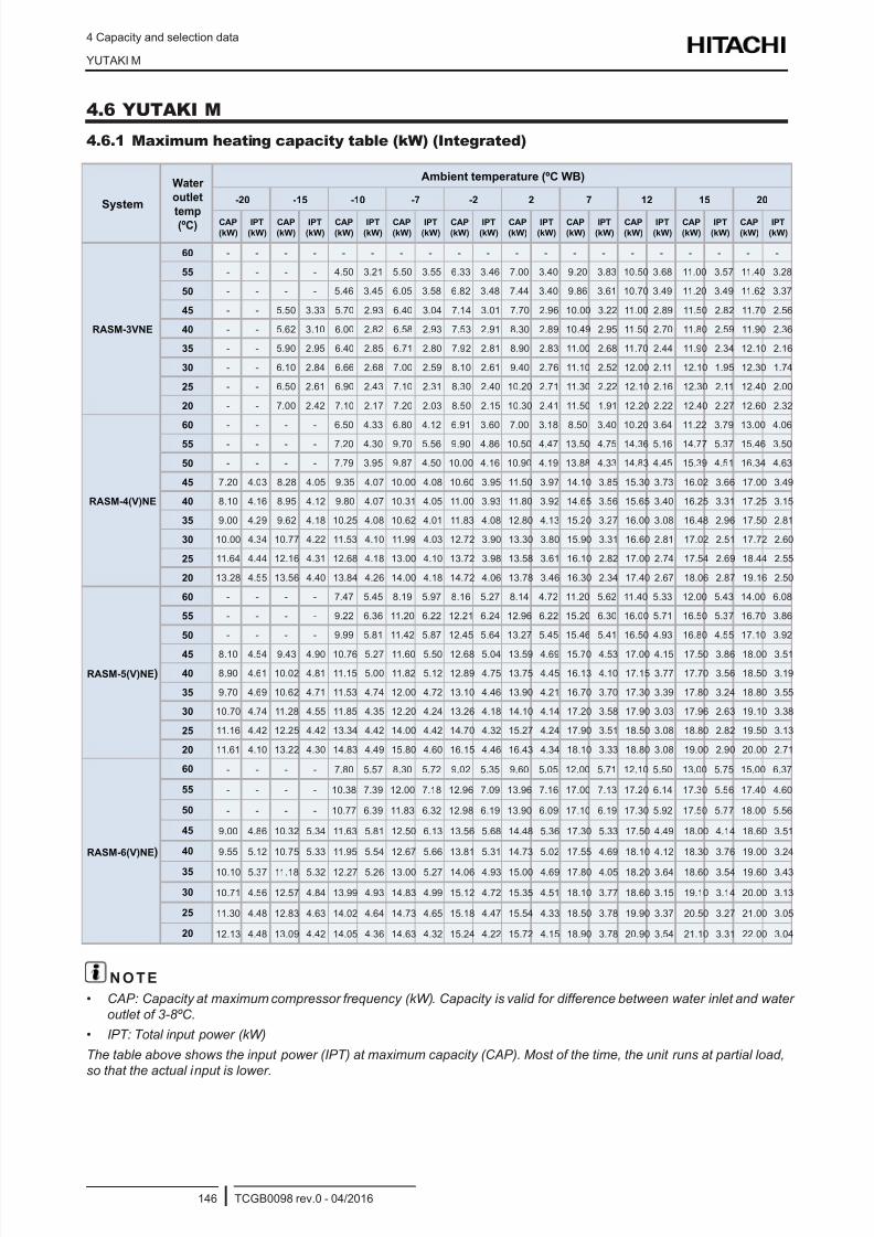
8/16/2019 Hitachi Yutaki Series 2016 Αντλίες θερμότητας
http://slidepdf.com/reader/full/hitachi-yutaki-series-2016- 156/256
4 Capacity and selection data
YUTAKI M
TCGB0098 rev.0 - 04/2016146
4.6 YUTAKI M
4.6.1 Maximum heating capacity table (kW) (Integrated)
System
Water
outlet
temp(ºC)
Ambient temperature (ºC WB)
-20 -15 -10 -7 -2 2 7 12 15 20
CAP
(kW)
IPT
(kW)
CAP
(kW)
IPT
(kW)
CAP
(kW)
IPT
(kW)
CAP
(kW)
IPT
(kW)
CAP
(kW)
IPT
(kW)
CAP
(kW)
IPT
(kW)
CAP
(kW)
IPT
(kW)
CAP
(kW)
IPT
(kW)
CAP
(kW)
IPT
(kW)
CAP
(kW)
IPT
(kW)
RASM-3VNE
60 - - - - - - - - - - - - - - - - - - - -
55 - - - - 4.50 3.21 5.50 3.55 6.33 3.46 7.00 3.40 9.20 3.83 10.50 3.68 11.00 3.57 11.40 3.28
50 - - - - 5.46 3.45 6.05 3.58 6.82 3.48 7.44 3.40 9.86 3.61 10.70 3.49 11.20 3.49 11.62 3.37
45 - - 5.50 3.33 5.70 2.93 6.40 3.04 7.14 3.01 7.70 2.96 10.00 3.22 11.00 2.89 11.50 2.82 11.70 2.56
40 - - 5.62 3.10 6.00 2.82 6.58 2.93 7.53 2.91 8.30 2.89 10.49 2.95 11.50 2.70 11.80 2.59 11.90 2.36
35 - - 5.90 2.95 6.40 2.85 6.71 2.80 7.92 2.81 8.90 2.83 11.00 2.68 11.70 2.44 11.90 2.34 12.10 2.16
30 - - 6.10 2.84 6.66 2.68 7.00 2.59 8.10 2.61 9.40 2.76 11.10 2.52 12.00 2.11 12.10 1.95 12.30 1.74
25 - - 6.50 2.61 6.90 2.43 7.10 2.31 8.30 2.40 10.20 2.71 11.30 2.22 12.10 2.16 12.30 2.11 12.40 2.00
20 - - 7.00 2.42 7.10 2.17 7.20 2.03 8.50 2.15 10.30 2.41 11.50 1.91 12.20 2.22 12.40 2.27 12.60 2.32
RASM-4(V)NE
60 - - - - 6.50 4.33 6.80 4.12 6.91 3.60 7.00 3.18 8.50 3.40 10.20 3.64 11.22 3.79 13.00 4.06
55 - - - - 7.20 4.30 9.70 5.56 9.90 4.86 10.50 4.47 13.50 4.75 14.36 5.16 14.77 5.37 15.46 3.50
50 - - - - 7.79 3.95 9.87 4.50 10.00 4.16 10.90 4.19 13.88 4.33 14.83 4.45 15.39 4.51 16.34 4.63
45 7.20 4.03 8.28 4.05 9.35 4.07 10.00 4.08 10.60 3.95 11.50 3.97 14.10 3.85 15.30 3.73 16.02 3.66 17.00 3.49
40 8.10 4.16 8.95 4.12 9.80 4.07 10.31 4.05 11.00 3.93 11.80 3.92 14.65 3.56 15.65 3.40 16.25 3.31 17.25 3.15
35 9.00 4.29 9.62 4.18 10.25 4.08 10.62 4.01 11.83 4.08 12.80 4.13 15.20 3.27 16.00 3.08 16.48 2.96 17.50 2.81
30 10.00 4.34 10.77 4.22 11.53 4.10 11.99 4.03 12.72 3.90 13.30 3.80 15.90 3.31 16.60 2.81 17.02 2.51 17.72 2.60
25 11.64 4.44 12.16 4.31 12.68 4.18 13.00 4.10 13.72 3.98 13.58 3.61 16.10 2.82 17.00 2.74 17.54 2.69 18.44 2.55
20 13.28 4.55 13.56 4.40 13.84 4.26 14.00 4.18 14.72 4.06 13.78 3.46 16.30 2.34 17.40 2.67 18.06 2.87 19.16 2.50
RASM-5(V)NE)
60 - - - - 7.47 5.45 8.19 5.97 8.16 5.27 8.14 4.72 11.20 5.62 11.40 5.33 12.00 5.43 14.00 6.08
55 - - - - 9.22 6.36 11.20 6.22 12.21 6.24 12.96 6.22 15.20 6.30 16.00 5.71 16.50 5.37 16.70 3.86
50 - - - - 9.99 5.81 11.42 5.87 12.45 5.64 13.27 5.45 15.46 5.41 16.50 4.93 16.80 4.55 17.10 3.92
45 8.10 4.54 9.43 4.90 10.76 5.27 11.60 5.50 12.68 5.04 13.59 4.69 15.70 4.53 17.00 4.15 17.50 3.86 18.00 3.51
40 8.90 4.61 10.02 4.81 11.15 5.00 11.82 5.12 12.89 4.75 13.75 4.45 16.13 4.10 17.15 3.77 17.70 3.56 18.50 3.19
35 9.70 4.69 10.62 4.71 11.53 4.74 12.00 4.72 13.10 4.46 13.90 4.21 16.70 3.70 17.30 3.39 17.80 3.24 18.80 3.55
30 10.70 4.74 11.28 4.55 11.85 4.35 12.20 4.24 13.26 4.18 14.10 4.14 17.20 3.58 17.90 3.03 17.96 2.63 19.10 3.38
25 11.16 4.42 12.25 4.42 13.34 4.42 14.00 4.42 14.70 4.32 15.27 4.24 17.90 3.51 18.50 3.08 18.80 2.82 19.50 3.13
20 11.61 4.10 13.22 4.30 14.83 4.49 15.80 4.60 16.15 4.46 16.43 4.34 18.10 3.33 18.80 3.08 19.00 2.90 20.00 2.71
RASM-6(V)NE)
60 - - - - 7.80 5.57 8.30 5.72 9.02 5.35 9.60 5.05 12.00 5.71 12.10 5.50 13.00 5.75 15.00 6.37
55 - - - - 10.38 7.39 12.00 7.18 12.96 7.09 13.96 7.16 17.00 7.13 17.20 6.14 17.30 5.56 17.40 4.60
50 - - - - 10.77 6.39 11.83 6.32 12.98 6.19 13.90 6.09 17.10 6.19 17.30 5.92 17.50 5.77 18.00 5.56
45 9.00 4.86 10.32 5.34 11.63 5.81 12.50 6.13 13.56 5.68 14.48 5.36 17.30 5.33 17.50 4.49 18.00 4.14 18.60 3.51
40 9.55 5.12 10.75 5.33 11.95 5.54 12.67 5.66 13.81 5.31 14.73 5.02 17.55 4.69 18.10 4.12 18.30 3.76 19.00 3.24
35 10.10 5.37 11.18 5.32 12.27 5.26 13.00 5.27 14.06 4.93 15.00 4.69 17.80 4.05 18.20 3.64 18.60 3.54 19.60 3.43
30 10.71 4.56 12.57 4.84 13.99 4.93 14.83 4.99 15.12 4.72 15.35 4.51 18.10 3.77 18.60 3.15 19.10 3.14 20.00 3.13
25 11.30 4.48 12.83 4.63 14.02 4.64 14.73 4.65 15.18 4.47 15.54 4.33 18.50 3.78 19.90 3.37 20.50 3.27 21.00 3.05
20 12.13 4.48 13.09 4.42 14.05 4.36 14.63 4.32 15.24 4.22 15.72 4.15 18.90 3.78 20.90 3.54 21.10 3.31 22.00 3.04
N O T E
• CAP: Capacity at maximum compressor frequency (kW). Capacity is valid for difference between water inlet and water
outlet of 3-8ºC.
• IPT: Total input power (kW)
The table above shows the input power (IPT) at maximum capacity (CAP). Most of the time, the unit runs at partial load,
so that the actual input is lower.
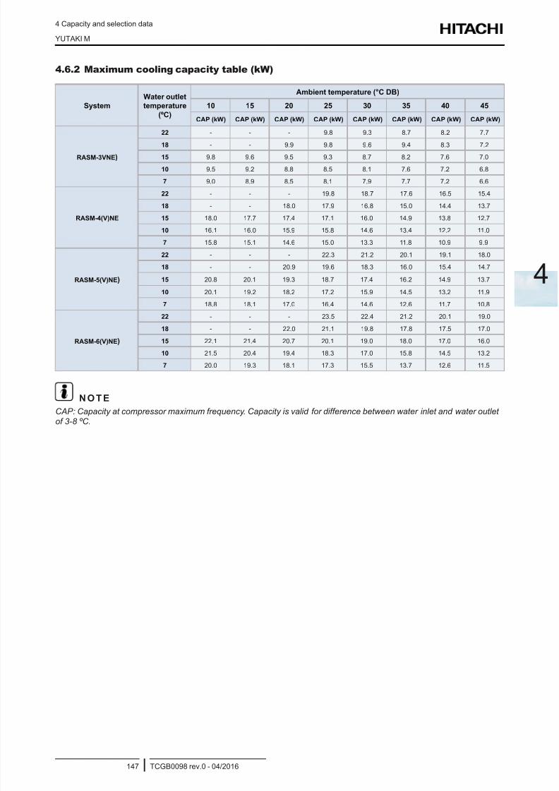
8/16/2019 Hitachi Yutaki Series 2016 Αντλίες θερμότητας
http://slidepdf.com/reader/full/hitachi-yutaki-series-2016- 157/256
4 Capacity and selection data
YUTAKI M
TCGB0098 rev.0 - 04/2016147
4
4.6.2 Maximum cooling capacity table (kW)
System
Water outlet
temperature
(ºC)
Ambient temperature (°C DB)
10 15 20 25 30 35 40 45
CAP (kW) CAP (kW) CAP (kW) CAP (kW) CAP (kW) CAP (kW) CAP (kW) CAP (kW)
RASM-3VNE)
22 - - - 9.8 9.3 8.7 8.2 7.7
18 - - 9.9 9.8 9.6 9.4 8.3 7.2
15 9.8 9.6 9.5 9.3 8.7 8.2 7.6 7.0
10 9.5 9.2 8.8 8.5 8.1 7.6 7.2 6.8
7 9.0 8.9 8.5 8.1 7.9 7.7 7.2 6.6
RASM-4(V)NE
22 - - - 19.8 18.7 17.6 16.5 15.4
18 - - 18.0 17.9 16.8 15.0 14.4 13.7
15 18.0 17.7 17.4 17.1 16.0 14.9 13.8 12.7
10 16.1 16.0 15.9 15.8 14.6 13.4 12.2 11.0
7 15.8 15.1 14.6 15.0 13.3 11.8 10.9 9.9
RASM-5(V)NE)
22 - - - 22.3 21.2 20.1 19.1 18.0
18 - - 20.9 19.6 18.3 16.0 15.4 14.7
15 20.8 20.1 19.3 18.7 17.4 16.2 14.9 13.7
10 20.1 19.2 18.2 17.2 15.9 14.5 13.2 11.9
7 18.8 18.1 17.0 16.4 14.6 12.6 11.7 10.8
RASM-6(V)NE)
22 - - - 23.5 22.4 21.2 20.1 19.0
18 - - 22.0 21.1 19.8 17.8 17.5 17.0
15 22.1 21.4 20.7 20.1 19.0 18.0 17.0 16.0
10 21.5 20.4 19.4 18.3 17.0 15.8 14.5 13.2
7 20.0 19.3 18.1 17.3 15.5 13.7 12.6 11.5
N O T E
CAP: Capacity at compressor maximum frequency. Capacity is valid for difference between water inlet and water outletof 3-8 ºC.

8/16/2019 Hitachi Yutaki Series 2016 Αντλίες θερμότητας
http://slidepdf.com/reader/full/hitachi-yutaki-series-2016- 158/256
4 Capacity and selection data
Correction factors
TCGB0098 rev.0 - 04/2016148
4.7 Correction factors
4.7.1 Piping length correction factor
The correction factor is based on the equivalent piping length in metres (EL) and the height difference between outdoor
unit and indoor unit in metres (H).
+H
-H
H: Height difference between indoor unit and outdoor unit (m).
- H>0: Outdoor unit is placed higher than indoor unit (m).
- H<0: Outdoor unit is placed lower than indoor unit (m).
L: Actual one-way piping length between indoor unit and outdoor unit (m).
EL: Equivalent one-way piping length between indoor unit and outdoor unit (m).
- One 90º elbow is 0.5 m. - One 180º bend is 1.5 m.
- One Multi-kit is 0.5 m.
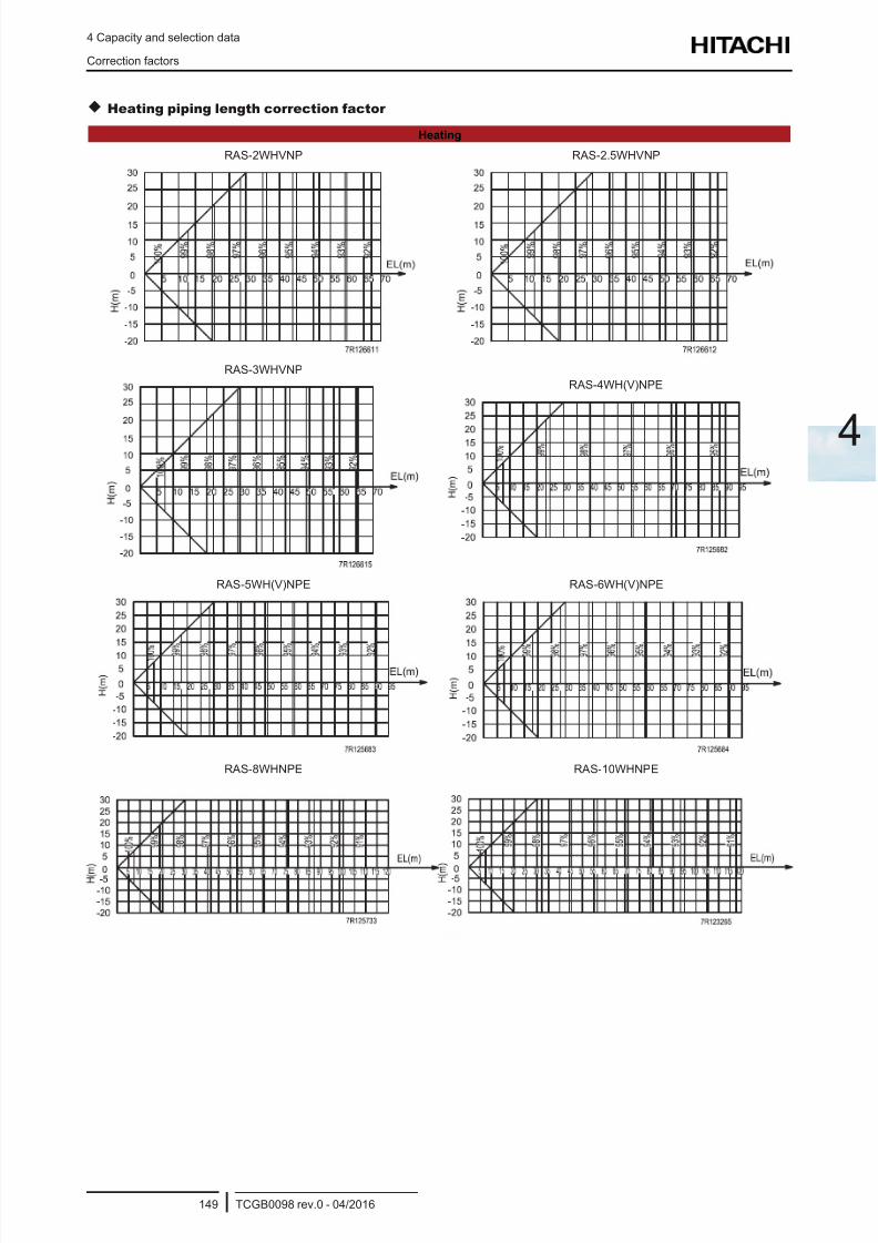
8/16/2019 Hitachi Yutaki Series 2016 Αντλίες θερμότητας
http://slidepdf.com/reader/full/hitachi-yutaki-series-2016- 159/256
4 Capacity and selection data
Correction factors
TCGB0098 rev.0 - 04/2016149
4
Heating piping length correction factor
Heating
RAS-2WHVNP RAS-2.5WHVNP
RAS-3WHVNP
RAS-4WH(V)NPE
RAS-5WH(V)NPE RAS-6WH(V)NPE
RAS-8WHNPE RAS-10WHNPE
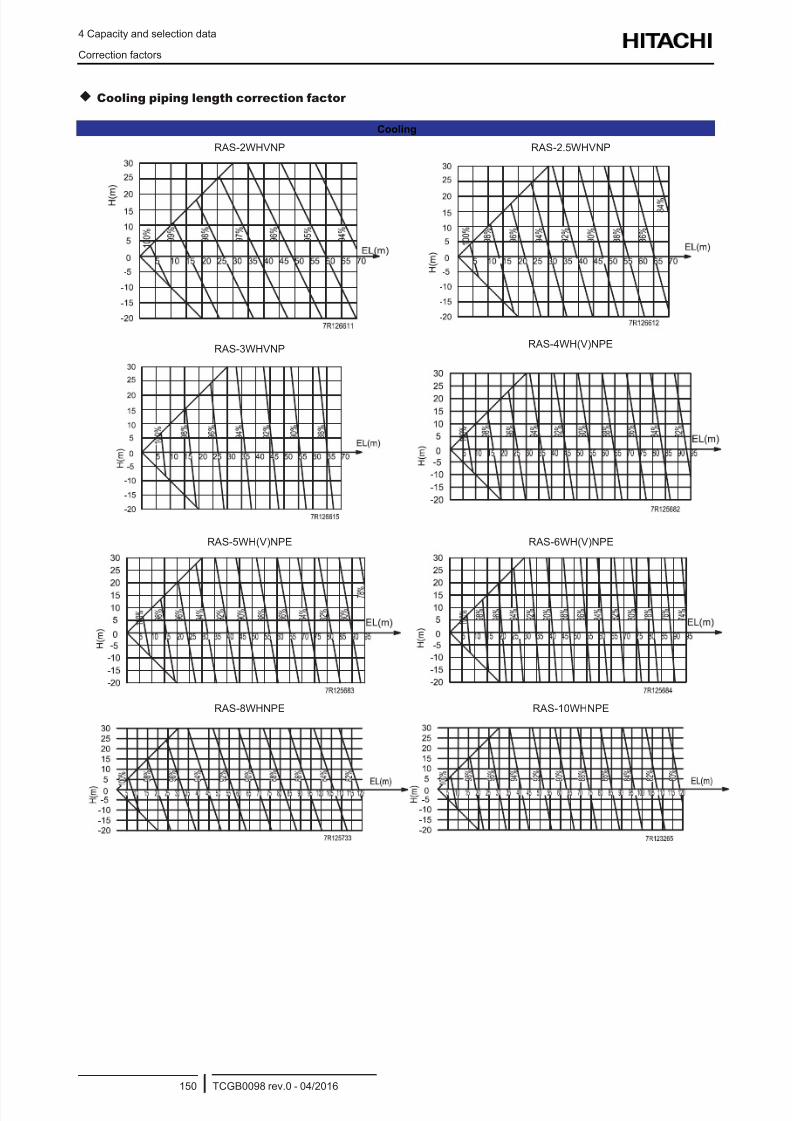
8/16/2019 Hitachi Yutaki Series 2016 Αντλίες θερμότητας
http://slidepdf.com/reader/full/hitachi-yutaki-series-2016- 160/256
4 Capacity and selection data
Correction factors
TCGB0098 rev.0 - 04/2016150
Cooling piping length correction factor
Cooling
RAS-2WHVNP RAS-2.5WHVNP
RAS-3WHVNP RAS-4WH(V)NPE
RAS-5WH(V)NPE RAS-6WH(V)NPE
RAS-8WHNPE RAS-10WHNPE
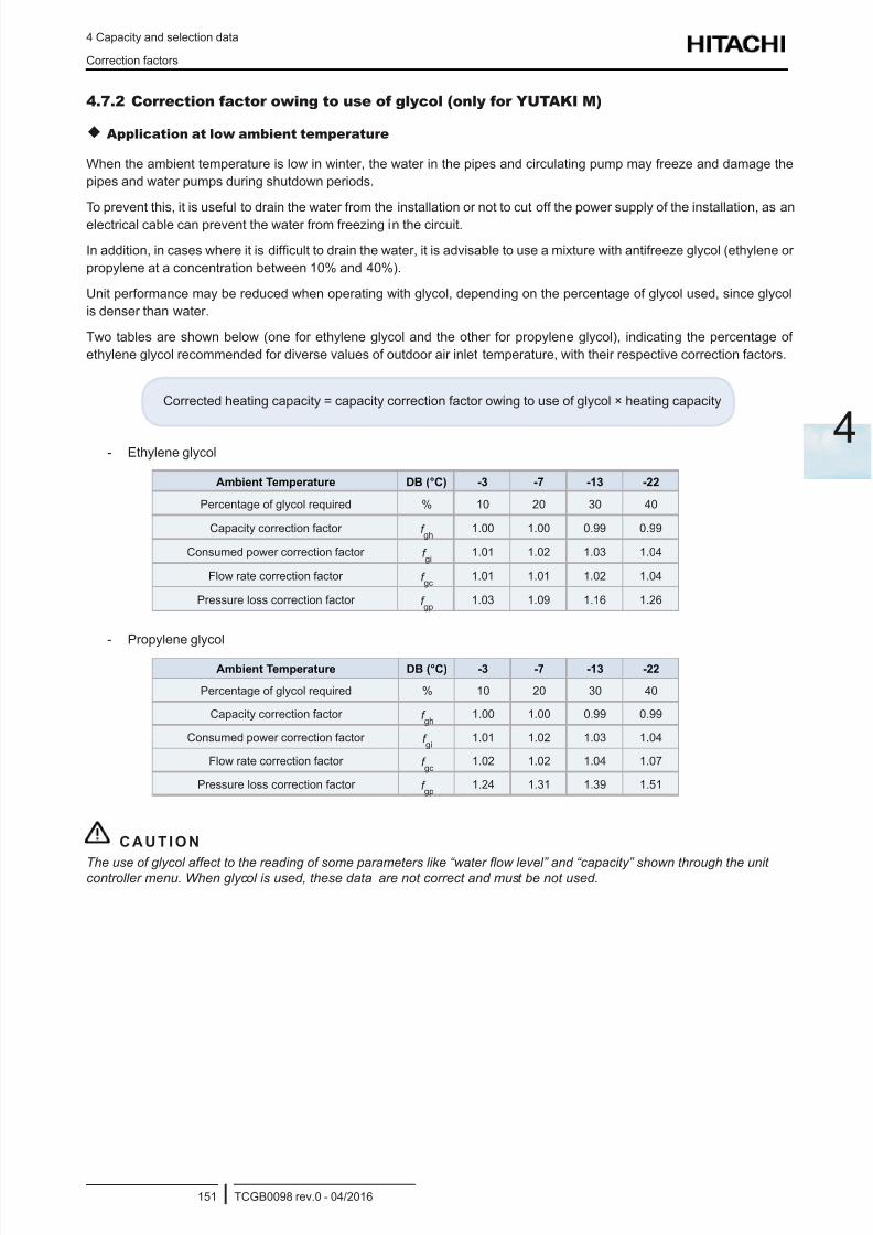
8/16/2019 Hitachi Yutaki Series 2016 Αντλίες θερμότητας
http://slidepdf.com/reader/full/hitachi-yutaki-series-2016- 161/256
4 Capacity and selection data
Correction factors
TCGB0098 rev.0 - 04/2016151
4
4.7.2 Correction factor owing to use of glycol (only for YUTAKI M)
Application at low ambient temperature
When the ambient temperature is low in winter, the water in the pipes and circulating pump may freeze and damage the
pipes and water pumps during shutdown periods.
To prevent this, it is useful to drain the water from the installation or not to cut off the power supply of the installation, as an
electrical cable can prevent the water from freezing in the circuit.
In addition, in cases where it is difcult to drain the water, it is advisable to use a mixture with antifreeze glycol (ethylene or
propylene at a concentration between 10% and 40%).
Unit performance may be reduced when operating with glycol, depending on the percentage of glycol used, since glycol
is denser than water.
Two tables are shown below (one for ethylene glycol and the other for propylene glycol), indicating the percentage of
ethylene glycol recommended for diverse values of outdoor air inlet temperature, with their respective correction factors.
Corrected heating capacity = capacity correction factor owing to use of glycol × heating capacity
- Ethylene glycol
Ambient Temperature DB (°C) -3 -7 -13 -22
Percentage of glycol required % 10 20 30 40
Capacity correction factor f gh
1.00 1.00 0.99 0.99
Consumed power correction factor f gi
1.01 1.02 1.03 1.04
Flow rate correction factor f gc
1.01 1.01 1.02 1.04
Pressure loss correction factor f gp
1.03 1.09 1.16 1.26
- Propylene glycol
Ambient Temperature DB (°C) -3 -7 -13 -22
Percentage of glycol required % 10 20 30 40
Capacity correction factor f gh
1.00 1.00 0.99 0.99
Consumed power correction factor f gi
1.01 1.02 1.03 1.04
Flow rate correction factor f gc
1.02 1.02 1.04 1.07
Pressure loss correction factor f gp
1.24 1.31 1.39 1.51
C A U T I O N
The use of glycol affect to the reading of some parameters like “water ow level” and “capacity” shown through the unitcontroller menu. When glycol is used, these data are not correct and must be not used.

8/16/2019 Hitachi Yutaki Series 2016 Αντλίες θερμότητας
http://slidepdf.com/reader/full/hitachi-yutaki-series-2016- 162/256
8/16/2019 Hitachi Yutaki Series 2016 Αντλίες θερμότητας
http://slidepdf.com/reader/full/hitachi-yutaki-series-2016- 163/256
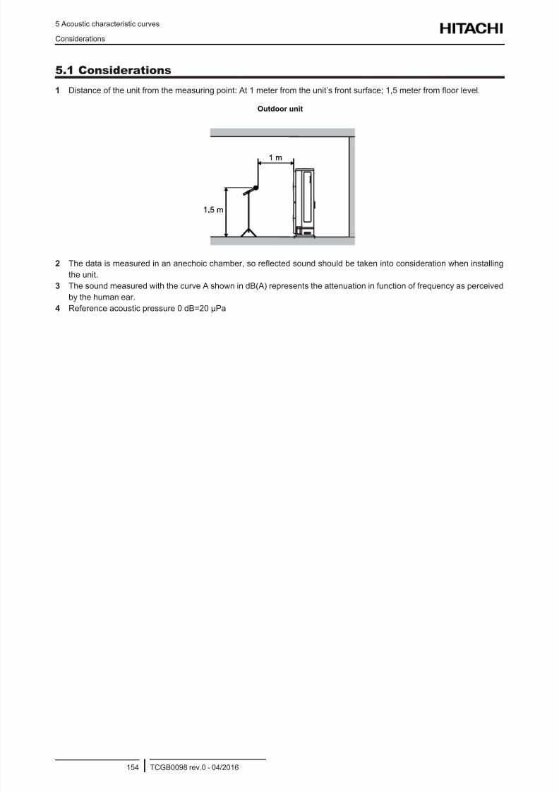
8/16/2019 Hitachi Yutaki Series 2016 Αντλίες θερμότητας
http://slidepdf.com/reader/full/hitachi-yutaki-series-2016- 164/256
5 Acoustic characteristic curves
Considerations
TCGB0098 rev.0 - 04/2016154
5.1 Considerations
1 Distance of the unit from the measuring point: At 1 meter from the unit’s front surface; 1,5 meter from oor level.
Outdoor unit
2 The data is measured in an anechoic chamber, so reected sound should be taken into consideration when installing
the unit.3 The sound measured with the curve A shown in dB(A) represents the attenuation in function of frequency as perceived
by the human ear.
4 Reference acoustic pressure 0 dB=20 μPa
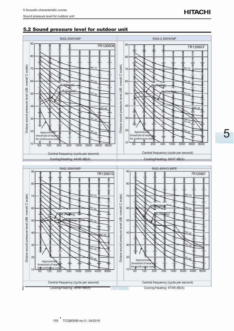
8/16/2019 Hitachi Yutaki Series 2016 Αντλίες θερμότητας
http://slidepdf.com/reader/full/hitachi-yutaki-series-2016- 165/256
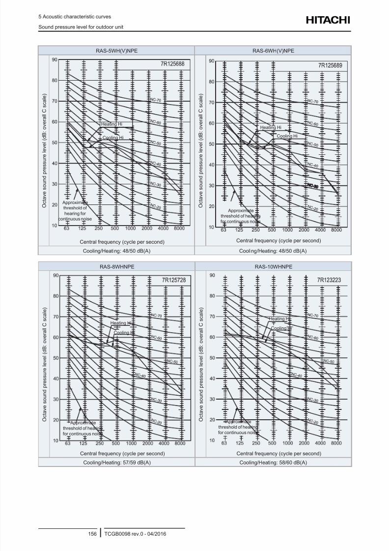
8/16/2019 Hitachi Yutaki Series 2016 Αντλίες θερμότητας
http://slidepdf.com/reader/full/hitachi-yutaki-series-2016- 166/256
5 Acoustic characteristic curves
Sound pressure level for outdoor unit
TCGB0098 rev.0 - 04/2016156
RAS-5WH(V)NPE RAS-6WH(V)NPE
O c t a v e
s o u n d p r e s s u r e l e v e l ( d B : o v e r a l l C
s c a l e
)
Heating Hi
Cooling Hi
Approximate
threshold of
hearing for
continuous noise
Central frequency (cycle per second)
O c t a v e
s o u n d p r e s s u r e l e v e l ( d B : o v e r a l l C
s c a l e
)
Heating Hi
Cooling Hi
Approximate
threshold of hearing
for continuous noise
Central frequency (cycle per second)
Cooling/Heating: 48/50 dB(A) Cooling/Heating: 48/50 dB(A)
RAS-8WHNPE RAS-10WHNPE
O c t a v e s o u n d p
r e s s u r e l e v e l ( d B : o v e r a l l C
s c a l e )
Heating Hi
Cooling Hi
Approximate
threshold of hearing
for continuous noise
Central frequency (cycle per second)
O c t a v e s o u n d p
r e s s u r e l e v e l ( d B : o v e r a l l C
s c a l e )
Heating Hi
Cooling Hi
Approximate
threshold of hearing
for continuous noise
Central frequency (cycle per second)
Cooling/Heating: 57/59 dB(A) Cooling/Heating: 58/60 dB(A)
8/16/2019 Hitachi Yutaki Series 2016 Αντλίες θερμότητας
http://slidepdf.com/reader/full/hitachi-yutaki-series-2016- 167/256
6 Working range
TCGB0098 rev.0 - 04/2016157
6
Index
6.1 Power supply working range ............................................................................................................... 158
6.2 Temperature working range................................................................................................................. 158
6.2.1 Space heating ............................................................................................................................................. 158
6.2.2 DHW ............................................................................................................................................................ 160
6.2.3 Swimming pool heating ............................................................................................................................... 161
6.2.4 Space cooling (Necessary cooling kit) ........................................................................................................161
6.3 Hydraulic working range ...................................................................................................................... 1626.3.1 Hydraulic data ............................................................................................................................................. 162
6.3.2 Pump performance curves ..........................................................................................................................163
6 . W o r k i n g r a n g e
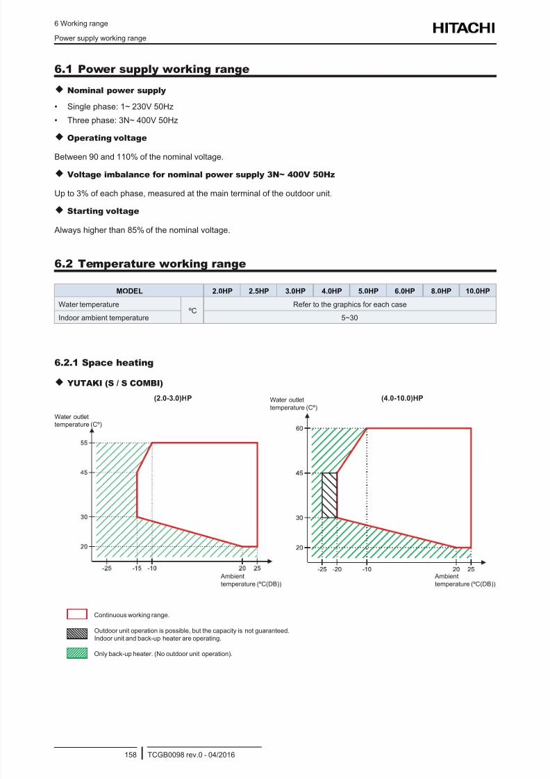
8/16/2019 Hitachi Yutaki Series 2016 Αντλίες θερμότητας
http://slidepdf.com/reader/full/hitachi-yutaki-series-2016- 168/256
6 Working range
Power supply working range
TCGB0098 rev.0 - 04/2016158
6.1 Power supply working range
Nominal power supply
• Single phase: 1~ 230V 50Hz
• Three phase: 3N~ 400V 50Hz
Operating voltage
Between 90 and 110% of the nominal voltage.
Voltage imbalance for nominal power supply 3N~ 400V 50Hz
Up to 3% of each phase, measured at the main terminal of the outdoor unit.
Starting voltage
Always higher than 85% of the nominal voltage.
6.2 Temperature working range
MODEL 2.0HP 2.5HP 3.0HP 4.0HP 5.0HP 6.0HP 8.0HP 10.0HP
Water temperatureºC
Refer to the graphics for each case
Indoor ambient temperature 5~30
6.2.1 Space heating
YUTAKI (S / S COMBI)
Water outlet
temperature (Cº)
Water outlet
temperature (Cº)
Ambient
temperature (ºC(DB))
(2.0-3.0)HP (4.0-10.0)HP
Ambient
temperature (ºC(DB))
Only back-up heater. (No outdoor unit operation).
Outdoor unit operation is possible, but the capacity is not guaranteed.
Indoor unit and back-up heater are operating.
Continuous working range.
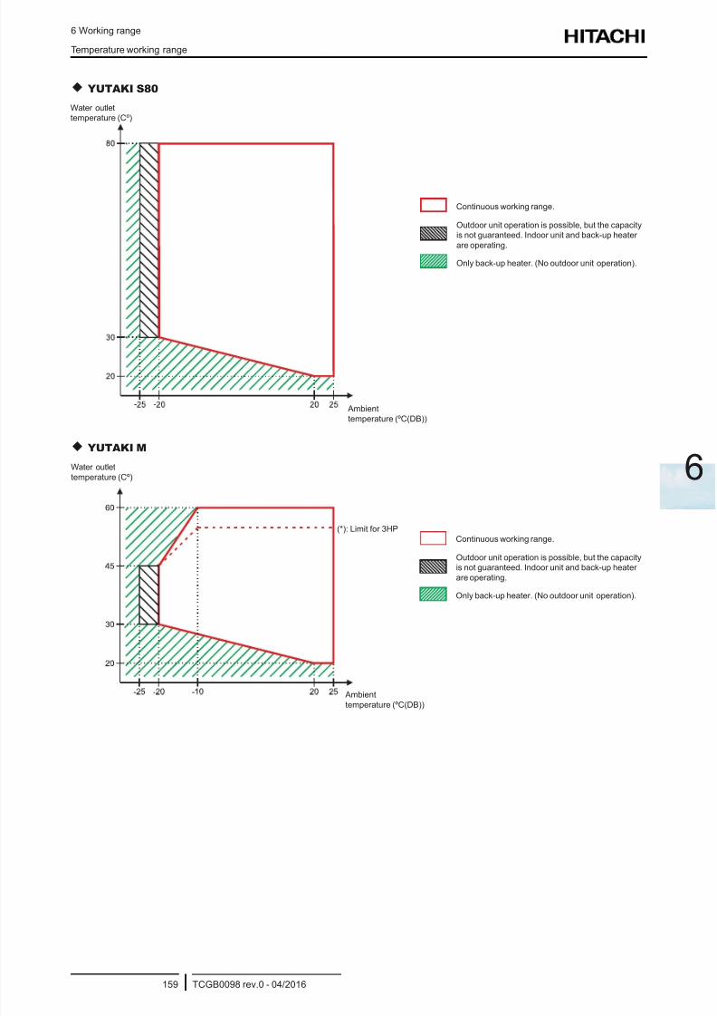
8/16/2019 Hitachi Yutaki Series 2016 Αντλίες θερμότητας
http://slidepdf.com/reader/full/hitachi-yutaki-series-2016- 169/256
6 Working range
Temperature working range
TCGB0098 rev.0 - 04/2016159
6
YUTAKI S80
Only back-up heater. (No outdoor unit operation).
Outdoor unit operation is possible, but the capacity
is not guaranteed. Indoor unit and back-up heater
are operating.
Continuous working range.
Water outlet
temperature (Cº)
Ambient
temperature (ºC(DB))
YUTAKI M
Water outlet
temperature (Cº)
Ambient
temperature (ºC(DB))
Only back-up heater. (No outdoor unit operation).
Outdoor unit operation is possible, but the capacity
is not guaranteed. Indoor unit and back-up heater
are operating.
Continuous working range.
(*): Limit for 3HP
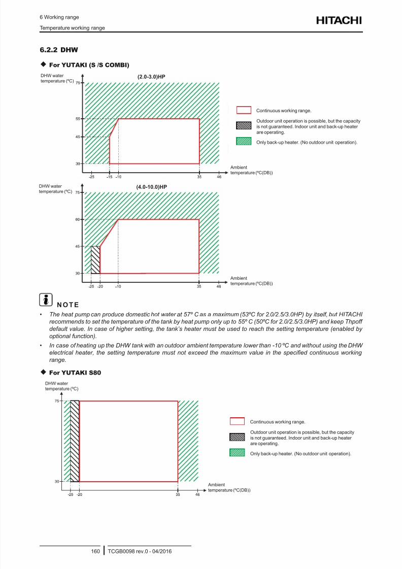
8/16/2019 Hitachi Yutaki Series 2016 Αντλίες θερμότητας
http://slidepdf.com/reader/full/hitachi-yutaki-series-2016- 170/256
6 Working range
Temperature working range
TCGB0098 rev.0 - 04/2016160
6.2.2 DHW
For YUTAKI (S /S COMBI)
DHW water
temperature (ºC)
Ambient
temperature (ºC(DB))
DHW water
temperature (ºC)
Ambient
temperature (ºC(DB))
(2.0-3.0)HP
(4.0-10.0)HP
Only back-up heater. (No outdoor unit operation).
Outdoor unit operation is possible, but the capacity
is not guaranteed. Indoor unit and back-up heater
are operating.
Continuous working range.
N O T E
• The heat pump can produce domestic hot water at 57º C as a maximum (53ºC for 2.0/2.5/3.0HP) by itself, but HITACHI
recommends to set the temperature of the tank by heat pump only up to 55º C (50ºC for 2.0/2.5/3.0HP) and keep Thpoff
default value. In case of higher setting, the tank’s heater must be used to reach the setting temperature (enabled by
optional function).
• In case of heating up the DHW tank with an outdoor ambient temperature lower than -10 ºC and without using the DHW
electrical heater, the setting temperature must not exceed the maximum value in the specied continuous working
range.
For YUTAKI S80
Only back-up heater. (No outdoor unit operation).
Outdoor unit operation is possible, but the capacity
is not guaranteed. Indoor unit and back-up heater
are operating.
Continuous working range.
DHW water
temperature (ºC)
Ambient
temperature (ºC(DB))
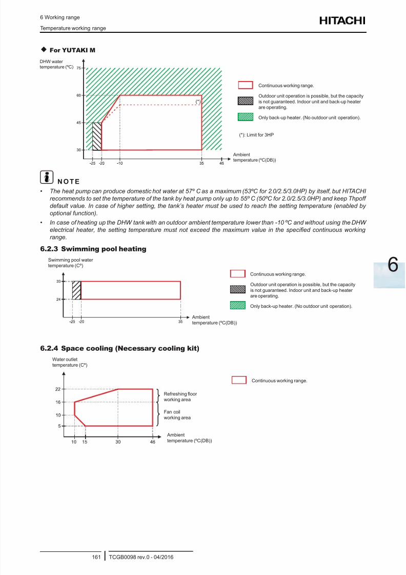
8/16/2019 Hitachi Yutaki Series 2016 Αντλίες θερμότητας
http://slidepdf.com/reader/full/hitachi-yutaki-series-2016- 171/256
6 Working range
Temperature working range
TCGB0098 rev.0 - 04/2016161
6
For YUTAKI M
(*): Limit for 3HP
Only back-up heater. (No outdoor unit operation).
Outdoor unit operation is possible, but the capacity
is not guaranteed. Indoor unit and back-up heaterare operating.
Continuous working range.
DHW water
temperature (ºC)
Ambient
temperature (ºC(DB))
(*)
N O T E
• The heat pump can produce domestic hot water at 57º C as a maximum (53ºC for 2.0/2.5/3.0HP) by itself, but HITACHI
recommends to set the temperature of the tank by heat pump only up to 55º C (50ºC for 2.0/2.5/3.0HP) and keep Thpoffdefault value. In case of higher setting, the tank’s heater must be used to reach the setting temperature (enabled by
optional function).
• In case of heating up the DHW tank with an outdoor ambient temperature lower than -10 ºC and without using the DHW
electrical heater, the setting temperature must not exceed the maximum value in the specied continuous working
range.
6.2.3 Swimming pool heating
Only back-up heater. (No outdoor unit operation).
Outdoor unit operation is possible, but the capacity
is not guaranteed. Indoor unit and back-up heater
are operating.
Continuous working range.
Swimming pool water
temperature (Cº)
Ambient
temperature (ºC(DB))
6.2.4 Space cooling (Necessary cooling kit)
Water outlet
temperature (Cº)
Ambient
temperature (ºC(DB))
Refreshing oor
working area
Fan coil
working area
Continuous working range.
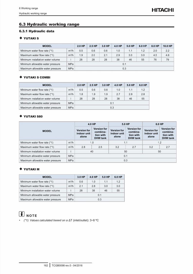
8/16/2019 Hitachi Yutaki Series 2016 Αντλίες θερμότητας
http://slidepdf.com/reader/full/hitachi-yutaki-series-2016- 172/256
6 Working range
Hydraulic working range
TCGB0098 rev.0 - 04/2016162
6.3 Hydraulic working range
6.3.1 Hydraulic data
YUTAKI S
MODEL 2.0 HP 2.5 HP 3.0 HP 4.0 HP 5.0 HP 6.0 HP 8.0 HP 10.0 HP
Minimum water ow rate (*1) m3/h 0.5 0.6 0.6 1.0 1.1 1.2 2.0 2.2
Maximum water ow rate (*1) m3/h 1.9 2.0 2.1 2.9 3.0 3.0 4.5 4.6
Minimum installation water volume l 28 28 28 38 46 55 76 79
Minimum allowable water pressure MPa 0.1
Maximum allowable water pressure MPa 0.3
YUTAKI S COMBI
MODEL 2.0 HP 2.5 HP 3.0 HP 4.0 HP 5.0 HP 6.0 HP
Minimum water ow rate (*1) m3/h 0.5 0.6 0.6 1.0 1.1 1.2
Maximum water ow rate (*1) m3/h 1.8 1.9 1.9 2.7 2.8 2.8
Minimum installation water volume l 28 28 28 38 46 55
Minimum allowable water pressure MPa 0.1
Maximum allowable water pressure MPa 0.3
YUTAKI S80
MODEL
4.0 HP 5.0 HP 6.0 HP
Version for
indoor unit
alone
Version for
combina-
tion with
DHW tank
Version for
indoor unit
alone
Version for
combina-
tion with
DHW tank
Version for
indoor unit
alone
Version for
combina-
tion with
DHW tank
Minimum water ow rate (*1) m3/h 1.0 1.1 1.2
Maximum water ow rate (*1) m3/h 2.8 2.5 3.2 2.7 3.2 2.7
Minimum installation water volume l 40 50 50
Minimum allowable water pressure MPa 0.1
Maximum allowable water pressure MPa 0.3
YUTAKI M
MODEL 3.0 HP 4.0 HP 5.0 HP 6.0 HP
Minimum water ow rate (*1) m3/h 0.6 1.0 1.1 1.2
Maximum water ow rate (*1) m3/h 2.1 2.8 3.0 3.0
Minimum installation water volume l 28 38 46 55
Minimum allowable water pressure MPa 0.1
Maximum allowable water pressure MPa 0.3
N O T E
• (*1): Values calculated based on a ΔT (inlet/outlet): 3~8 ºC
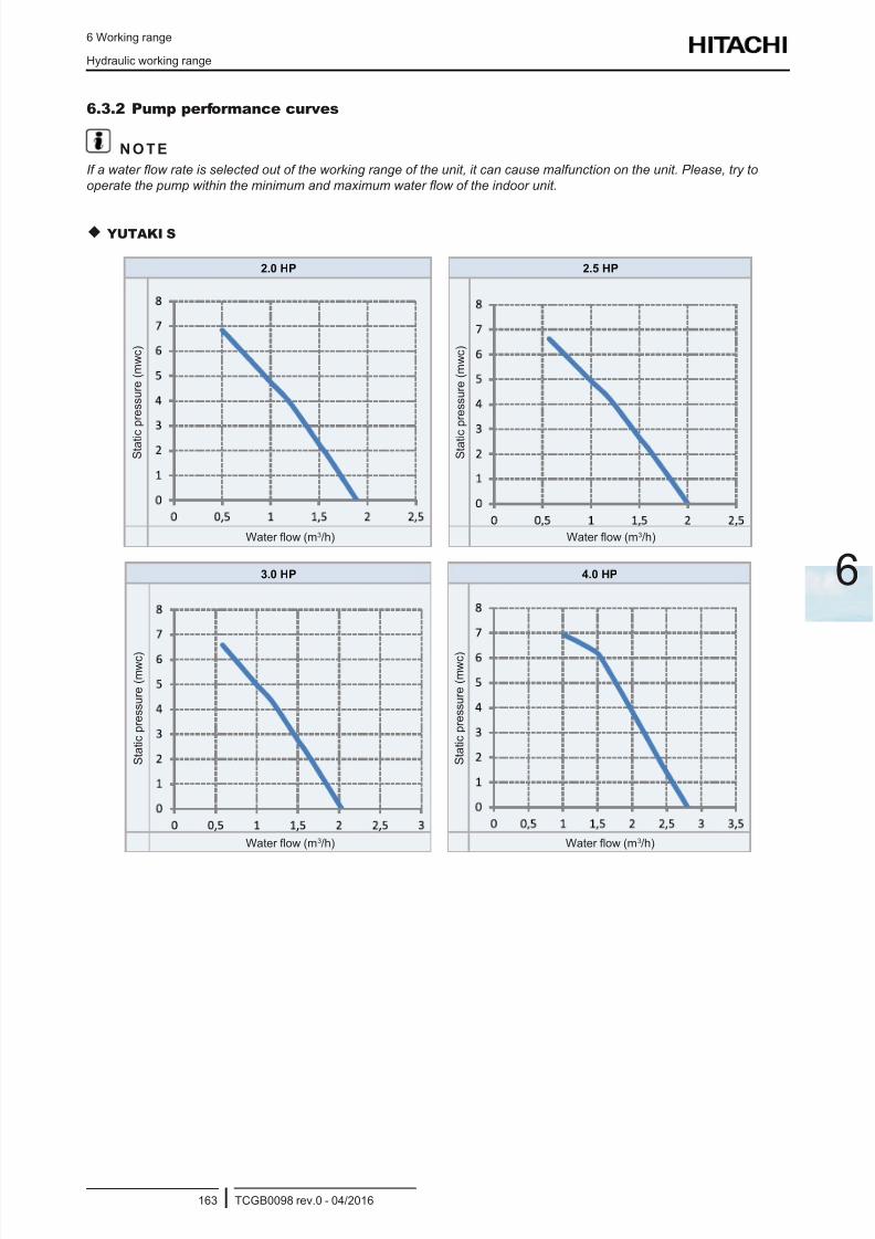
8/16/2019 Hitachi Yutaki Series 2016 Αντλίες θερμότητας
http://slidepdf.com/reader/full/hitachi-yutaki-series-2016- 173/256
6 Working range
Hydraulic working range
TCGB0098 rev.0 - 04/2016163
6
6.3.2 Pump performance curves
N O T E
If a water ow rate is selected out of the working range of the unit, it can cause malfunction on the unit. Please, try to
operate the pump within the minimum and maximum water ow of the indoor unit.
YUTAKI S
2.0 HP 2.5 HP
S t a t i c
p r e s s u r e ( m w c )
S t a t i c
p r e s s u r e ( m w c )
Water ow (m3/h) Water ow (m3/h)
3.0 HP 4.0 HP
S t a t i c p r e s s u r e ( m w c )
S t a t i c p r e s s u r e ( m w c )
Water ow (m3/h) Water ow (m3/h)
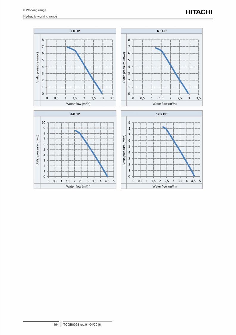
8/16/2019 Hitachi Yutaki Series 2016 Αντλίες θερμότητας
http://slidepdf.com/reader/full/hitachi-yutaki-series-2016- 174/256
6 Working range
Hydraulic working range
TCGB0098 rev.0 - 04/2016164
5.0 HP 6.0 HP
S t a t i c p r e s s u r e ( m
w c )
S t a t i c p r e s s u r e ( m
w c )
Water ow (m3/h) Water ow (m3/h)
8.0 HP 10.0 HP
S t a t i c p r e s s u r e ( m w c )
S t a t i c p r e s s u r e ( m w c )
Water ow (m3/h) Water ow (m3/h)
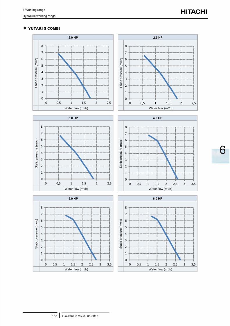
8/16/2019 Hitachi Yutaki Series 2016 Αντλίες θερμότητας
http://slidepdf.com/reader/full/hitachi-yutaki-series-2016- 175/256
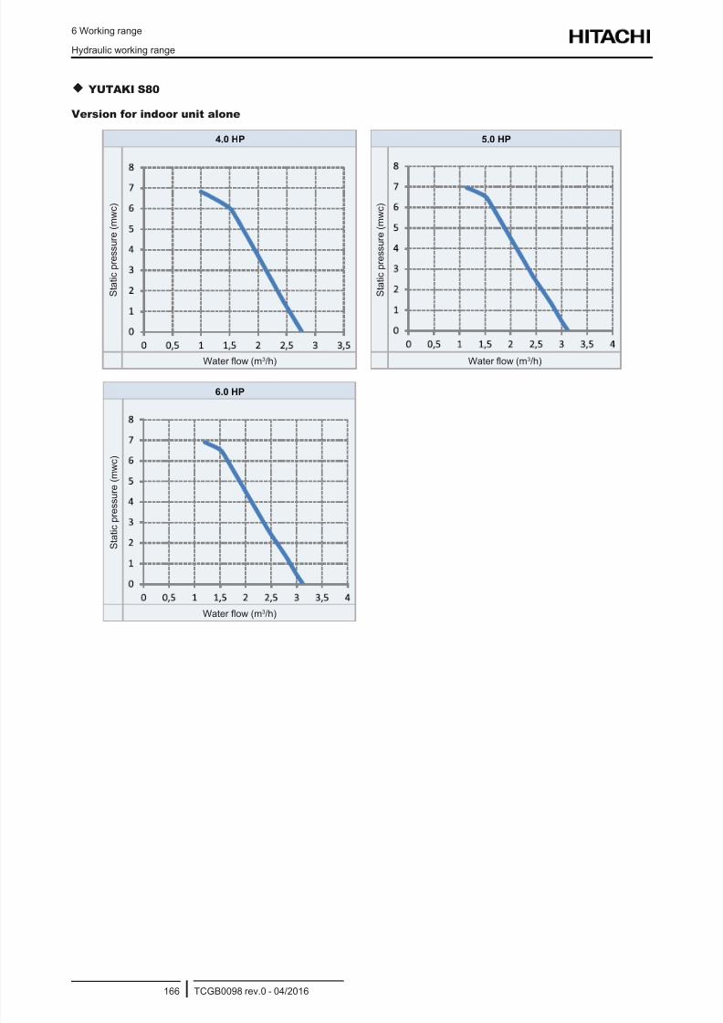
8/16/2019 Hitachi Yutaki Series 2016 Αντλίες θερμότητας
http://slidepdf.com/reader/full/hitachi-yutaki-series-2016- 176/256
6 Working range
Hydraulic working range
TCGB0098 rev.0 - 04/2016166
YUTAKI S80
Version for indoor unit alone
4.0 HP 5.0 HP
S t a t i c p r e s s u r e ( m w c )
S t a t i c p r e s s u r e ( m w c )
Water ow (m3/h) Water ow (m3/h)
6.0 HP
S t a
t i c p r e s s u r e ( m w c )
Water ow (m3/h)
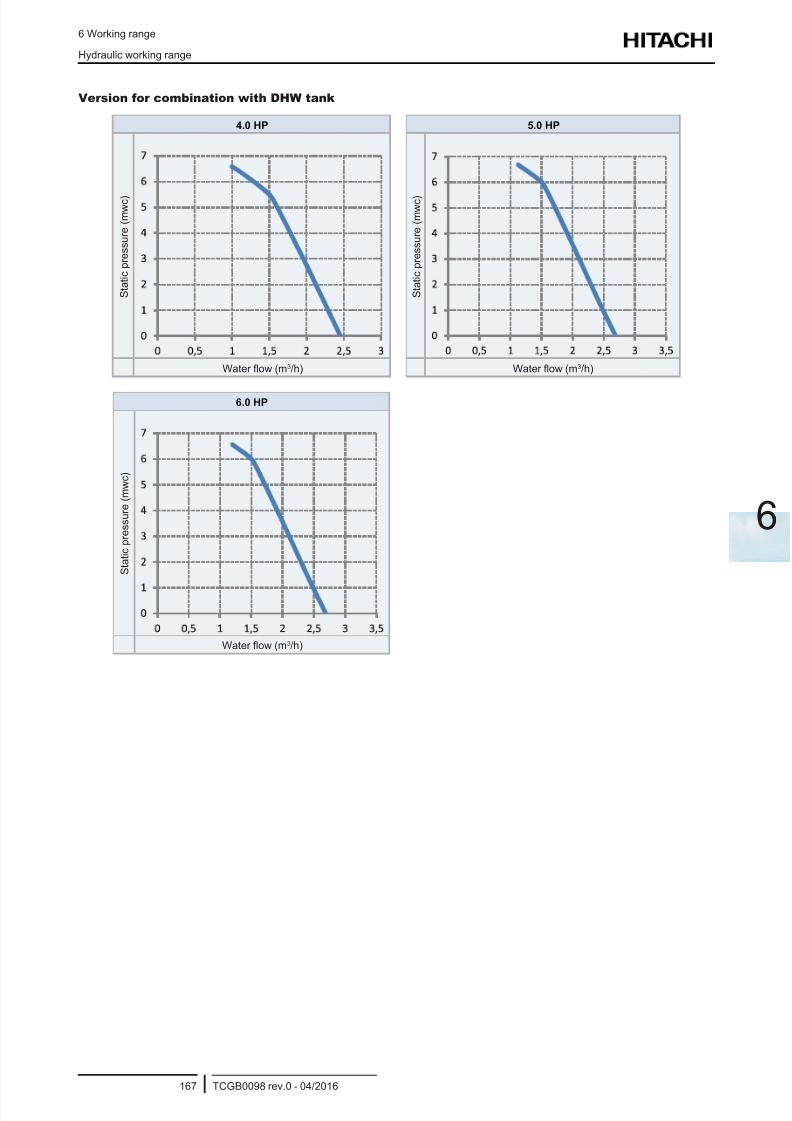
8/16/2019 Hitachi Yutaki Series 2016 Αντλίες θερμότητας
http://slidepdf.com/reader/full/hitachi-yutaki-series-2016- 177/256
6 Working range
Hydraulic working range
TCGB0098 rev.0 - 04/2016167
6
Version for combination with DHW tank
4.0 HP 5.0 HP
S t a t i c p r e s s u r e ( m w c )
S t a t i c p r e s s u r e ( m w c )
Water ow (m3/h) Water ow (m3/h)
6.0 HP
S t a t i c p r e s s u r e ( m w c )
Water ow (m3/h)
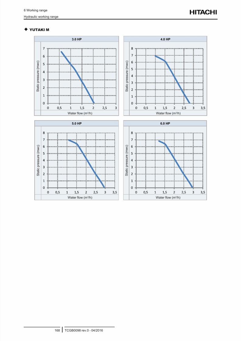
8/16/2019 Hitachi Yutaki Series 2016 Αντλίες θερμότητας
http://slidepdf.com/reader/full/hitachi-yutaki-series-2016- 178/256
6 Working range
Hydraulic working range
TCGB0098 rev.0 - 04/2016168
YUTAKI M
3.0 HP 4.0 HP
S t a t i c p r e s s u r e ( m w c )
S t a t i c p r e s s u r e ( m w c )
Water ow (m3/h) Water ow (m3/h)
5.0 HP 6.0 HP
S t a t i c p r e s s u r e ( m w c )
S t a t i c p r e s s u r e ( m w c )
Water ow (m3/h) Water ow (m3/h)
8/16/2019 Hitachi Yutaki Series 2016 Αντλίες θερμότητας
http://slidepdf.com/reader/full/hitachi-yutaki-series-2016- 179/256
7 General dimensions
TCGB0098 rev.0 - 04/2016169
7
Index
7.1 Name of parts and Dimensional data ..................................................................................................170
7.1.1 Split system - Outdoor unit ..........................................................................................................................170
7.1.2 Split system - Indoor unit ............................................................................................................................. 172
7.1.2.1 YUTAKI S .................................................................................................................................... 172
7.1.2.2 YUTAKI S COMBI .......................................................................................................................175
7.1.2.3 YUTAKI S80 ................................................................................................................................ 180
7.1.3 Monobloc system - YUTAKI M..................................................................................................................... 183
7.2 Service space ...................................................................................................................................... 185
7.2.1 Split system - Outdoor unit ..........................................................................................................................185
7.2.2 Split system - Indoor unit ............................................................................................................................. 186
7.2.2.1 YUTAKI S .................................................................................................................................... 186
7.2.2.2 YUTAKI S COMBI .......................................................................................................................186
7.2.3 Monobloc system - YUTAKI M..................................................................................................................... 190
7 . G e n e r a l d i m e n s i o n s
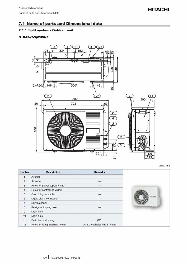
8/16/2019 Hitachi Yutaki Series 2016 Αντλίες θερμότητας
http://slidepdf.com/reader/full/hitachi-yutaki-series-2016- 180/256
7 General dimensions
Name of parts and Dimensional data
TCGB0098 rev.0 - 04/2016170
7.1 Name of parts and Dimensional data
7.1.1 Split system - Outdoor unit
RAS-(2-3)WHVNP
A
B
Units: mm
Number Description Remarks
1 Air inlet —
2 Air outlet —
3 Holes for power supply wiring —4 Holes for control line wiring —
5 Gas piping connection —
6 Liquid piping connection —
7 Service panel —
8 Refrigerant piping hole —
9 Drain hole —
10 Drain hole —
11 Earth terminal wiring (M5)
12 Holes for xing machine to wall A: 2-U cut holes / B: 2 - holes
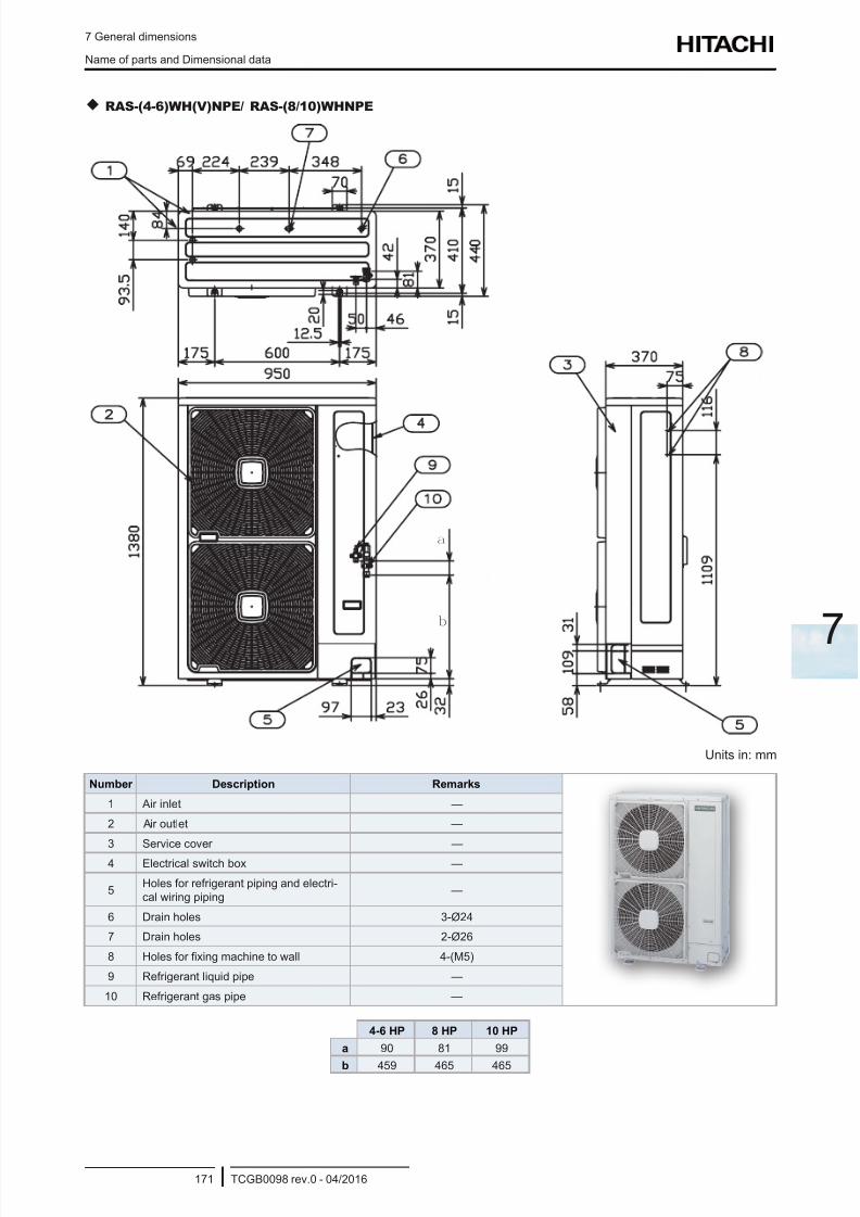
8/16/2019 Hitachi Yutaki Series 2016 Αντλίες θερμότητας
http://slidepdf.com/reader/full/hitachi-yutaki-series-2016- 181/256
7 General dimensions
Name of parts and Dimensional data
TCGB0098 rev.0 - 04/2016171
7
RAS-(4-6)WH(V)NPE/ RAS-(8/10)WHNPE
a
b
Units in: mm
Number Description Remarks
1 Air inlet —
2 Air outlet —
3 Service cover —
4 Electrical switch box —
5Holes for refrigerant piping and electri-
cal wiring piping—
6 Drain holes 3-Ø24
7 Drain holes 2-Ø26
8 Holes for xing machine to wall 4-(M5)
9 Refrigerant liquid pipe —
10 Refrigerant gas pipe —
4-6 HP 8 HP 10 HP
a 90 81 99
b 459 465 465
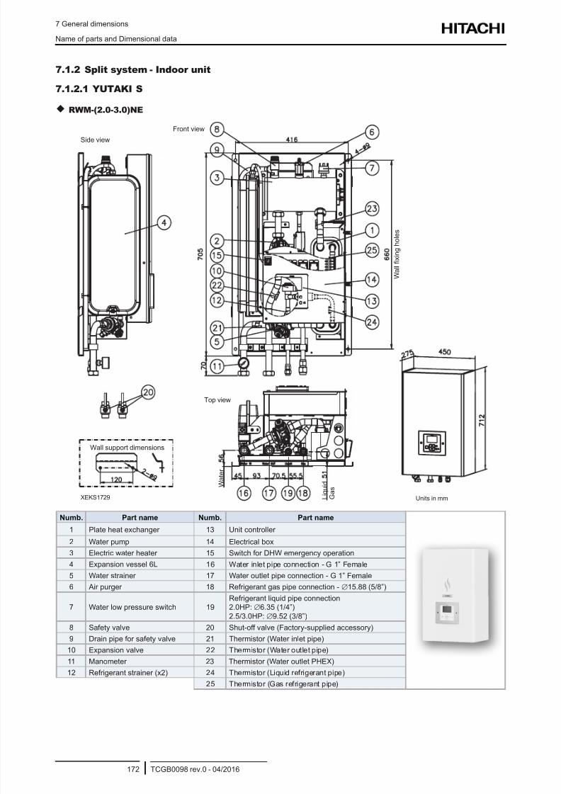
8/16/2019 Hitachi Yutaki Series 2016 Αντλίες θερμότητας
http://slidepdf.com/reader/full/hitachi-yutaki-series-2016- 182/256
7 General dimensions
Name of parts and Dimensional data
TCGB0098 rev.0 - 04/2016172
7.1.2 Split system - Indoor unit
7.1.2.1 YUTAKI S
RWM-(2.0-3.0)NE
Front view
Top view
Side view
Wall support dimensions
W
a l l x i n g h o l e s
W a t e r
L i q u i d
G a s
XEKS1729 Units in mm
Numb. Part name Numb. Part name
1 Plate heat exchanger 13 Unit controller
2 Water pump 14 Electrical box
3 Electric water heater 15 Switch for DHW emergency operation4 Expansion vessel 6L 16 Water inlet pipe connection - G 1” Female
5 Water strainer 17 Water outlet pipe connection - G 1” Female
6 Air purger 18 Refrigerant gas pipe connection - ∅15.88 (5/8”)
7 Water low pressure switch 19Refrigerant liquid pipe connection2.0HP: ∅6.35 (1/4”)
2.5/3.0HP:∅9.52 (3/8”)
8 Safety valve 20 Shut-off valve (Factory-supplied accessory)
9 Drain pipe for safety valve 21 Thermistor (Water inlet pipe)
10 Expansion valve 22 Thermistor (Water outlet pipe)
11 Manometer 23 Thermistor (Water outlet PHEX)
12 Refrigerant strainer (x2) 24 Thermistor (Liquid refrigerant pipe)
25 Thermistor (Gas refrigerant pipe)
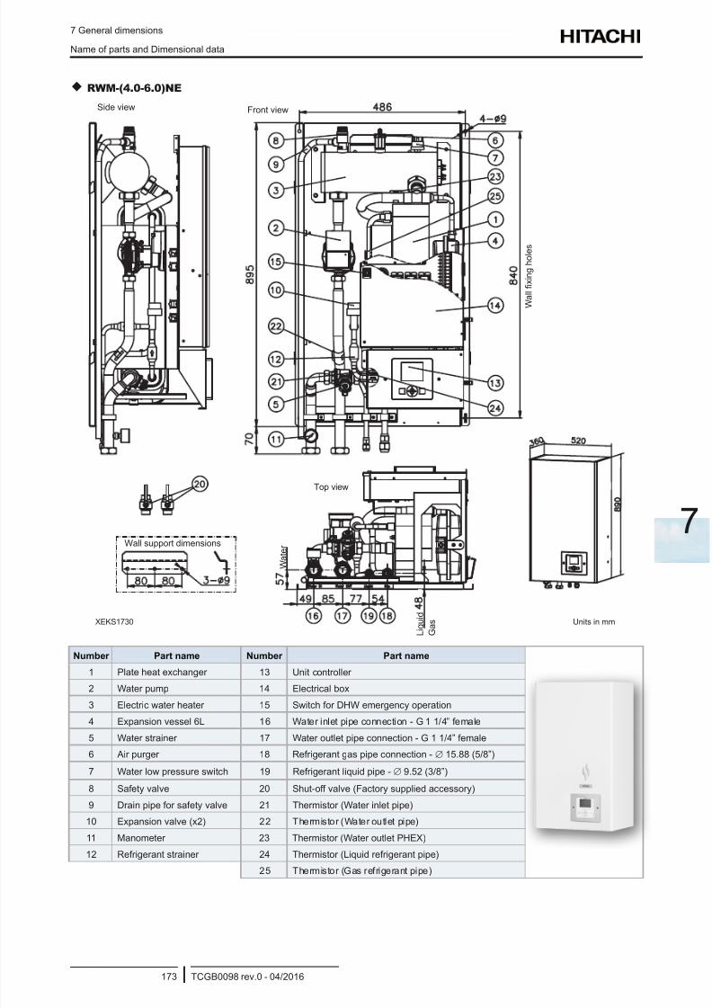
8/16/2019 Hitachi Yutaki Series 2016 Αντλίες θερμότητας
http://slidepdf.com/reader/full/hitachi-yutaki-series-2016- 183/256
7 General dimensions
Name of parts and Dimensional data
TCGB0098 rev.0 - 04/2016173
7
RWM-(4.0-6.0)NE
Top view
Side view Front view
Wall support dimensions
W a t e r
G a s
L i q u i d
Units in mmXEKS1730
W a l l x i n g h o l e s
Number Part name Number Part name
1 Plate heat exchanger 13 Unit controller
2 Water pump 14 Electrical box
3 Electric water heater 15 Switch for DHW emergency operation4 Expansion vessel 6L 16 Water inlet pipe connection - G 1 1/4” female
5 Water strainer 17 Water outlet pipe connection - G 1 1/4” female
6 Air purger 18 Refrigerant gas pipe connection - ∅ 15.88 (5/8”)
7 Water low pressure switch 19 Refrigerant liquid pipe - ∅ 9.52 (3/8”)
8 Safety valve 20 Shut-off valve (Factory supplied accessory)
9 Drain pipe for safety valve 21 Thermistor (Water inlet pipe)
10 Expansion valve (x2) 22 Thermistor (Water outlet pipe)
11 Manometer 23 Thermistor (Water outlet PHEX)
12 Refrigerant strainer 24 Thermistor (Liquid refrigerant pipe)
25 Thermistor (Gas refrigerant pipe)
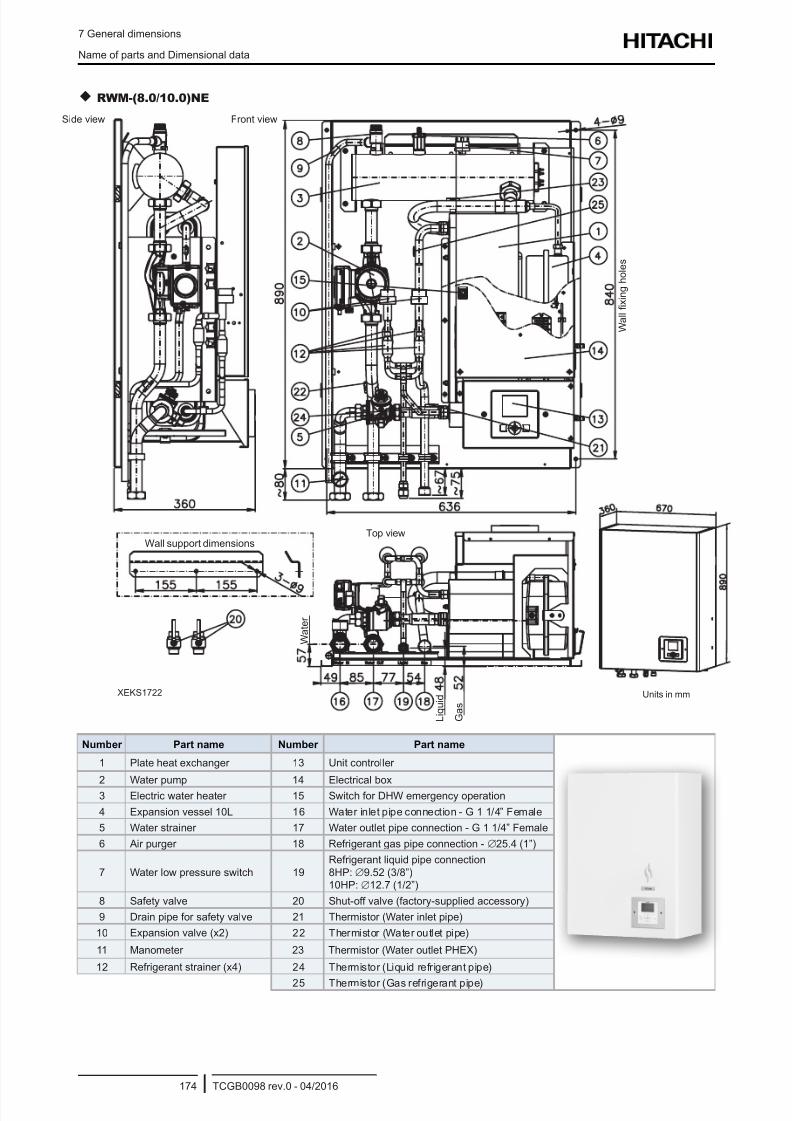
8/16/2019 Hitachi Yutaki Series 2016 Αντλίες θερμότητας
http://slidepdf.com/reader/full/hitachi-yutaki-series-2016- 184/256
7 General dimensions
Name of parts and Dimensional data
TCGB0098 rev.0 - 04/2016174
RWM-(8.0/10.0)NE
Side view Front view
Top view
XEKS1722 Units in mm
L i q u i d
G a s
Wall support dimensions
W a t e r
W a l l x i n g h o l e s
Number Part name Number Part name
1 Plate heat exchanger 13 Unit controller
2 Water pump 14 Electrical box
3 Electric water heater 15 Switch for DHW emergency operation
4 Expansion vessel 10L 16 Water inlet pipe connection - G 1 1/4” Female
5 Water strainer 17 Water outlet pipe connection - G 1 1/4” Female
6 Air purger 18 Refrigerant gas pipe connection - ∅25.4 (1”)
7 Water low pressure switch 19
Refrigerant liquid pipe connection
8HP: ∅9.52 (3/8”)10HP: ∅12.7 (1/2”)
8 Safety valve 20 Shut-off valve (factory-supplied accessory)
9 Drain pipe for safety valve 21 Thermistor (Water inlet pipe)
10 Expansion valve (x2) 22 Thermistor (Water outlet pipe)
11 Manometer 23 Thermistor (Water outlet PHEX)
12 Refrigerant strainer (x4) 24 Thermistor (Liquid refrigerant pipe)
25 Thermistor (Gas refrigerant pipe)
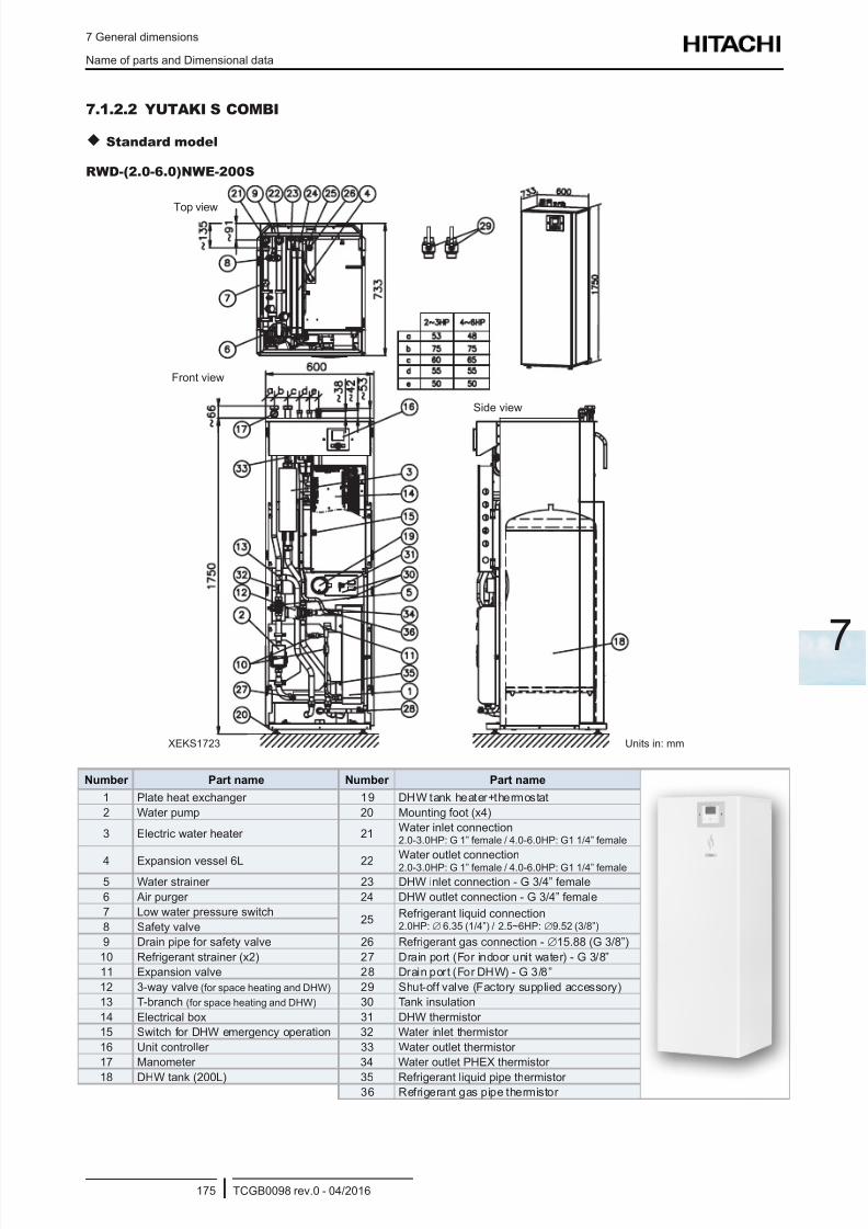
8/16/2019 Hitachi Yutaki Series 2016 Αντλίες θερμότητας
http://slidepdf.com/reader/full/hitachi-yutaki-series-2016- 185/256
7 General dimensions
Name of parts and Dimensional data
TCGB0098 rev.0 - 04/2016175
7
7.1.2.2 YUTAKI S COMBI
Standard model
RWD-(2.0-6.0)NWE-200S
Units in: mm
Front view
Top view
Side view
XEKS1723
Number Part name Number Part name
1 Plate heat exchanger 19 DHW tank heater+thermostat
2 Water pump 20 Mounting foot (x4)
3 Electric water heater 21Water inlet connection2.0-3.0HP: G 1” female / 4.0-6.0HP: G1 1/4” female
4 Expansion vessel 6L 22Water outlet connection2.0-3.0HP: G 1” female / 4.0-6.0HP: G1 1/4” female
5 Water strainer 23 DHW inlet connection - G 3/4” female
6 Air purger 24 DHW outlet connection - G 3/4” female
7 Low water pressure switch25
Refrigerant liquid connection2.0HP:∅ 6.35 (1/4”) / 2.5~6HP:∅9.52 (3/8”)8 Safety valve
9 Drain pipe for safety valve 26 Refrigerant gas connection - ∅15.88 (G 3/8”)
10 Refrigerant strainer (x2) 27 Drain port (For indoor unit water) - G 3/8”
11 Expansion valve 28 Drain port (For DHW) - G 3/8”
12 3-way valve (for space heating and DHW) 29 Shut-off valve (Factory supplied accessory)
13 T-branch (for space heating and DHW) 30 Tank insulation
14 Electrical box 31 DHW thermistor
15 Switch for DHW emergency operation 32 Water inlet thermistor
16 Unit controller 33 Water outlet thermistor
17 Manometer 34 Water outlet PHEX thermistor
18 DHW tank (200L) 35 Refrigerant liquid pipe thermistor 36 Refrigerant gas pipe thermistor
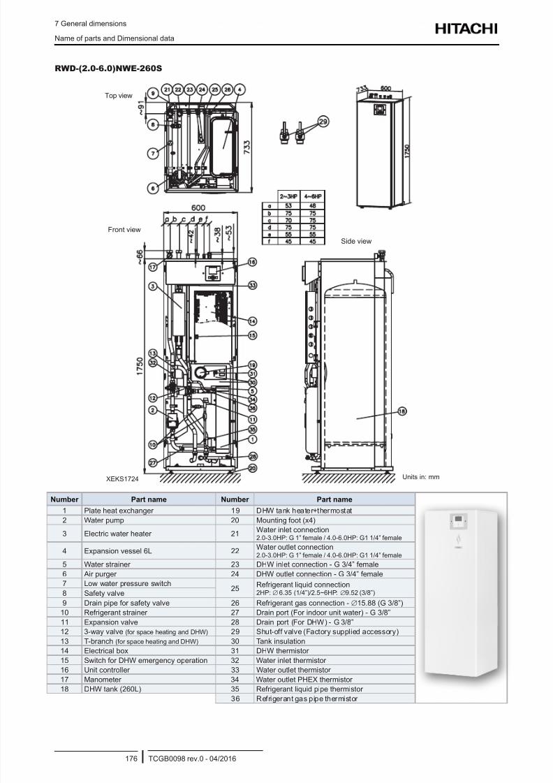
8/16/2019 Hitachi Yutaki Series 2016 Αντλίες θερμότητας
http://slidepdf.com/reader/full/hitachi-yutaki-series-2016- 186/256
7 General dimensions
Name of parts and Dimensional data
TCGB0098 rev.0 - 04/2016176
RWD-(2.0-6.0)NWE-260S
Top view
Front view
Side view
XEKS1724 Units in: mm
Number Part name Number Part name
1 Plate heat exchanger 19 DHW tank heater+thermostat
2 Water pump 20 Mounting foot (x4)
3 Electric water heater 21Water inlet connection2.0-3.0HP: G 1” female / 4.0-6.0HP: G1 1/4” female
4 Expansion vessel 6L 22 Water outlet connection2.0-3.0HP: G 1” female / 4.0-6.0HP: G1 1/4” female
5 Water strainer 23 DHW inlet connection - G 3/4” female
6 Air purger 24 DHW outlet connection - G 3/4” female
7 Low water pressure switch25
Refrigerant liquid connection2HP:∅ 6.35 (1/4”)/2.5~6HP: ∅9.52 (3/8”)8 Safety valve
9 Drain pipe for safety valve 26 Refrigerant gas connection - ∅15.88 (G 3/8”)
10 Refrigerant strainer 27 Drain port (For indoor unit water) - G 3/8”
11 Expansion valve 28 Drain port (For DHW) - G 3/8”
12 3-way valve (for space heating and DHW) 29 Shut-off valve (Factory supplied accessory)
13 T-branch (for space heating and DHW) 30 Tank insulation
14 Electrical box 31 DHW thermistor
15 Switch for DHW emergency operation 32 Water inlet thermistor
16 Unit controller 33 Water outlet thermistor
17 Manometer 34 Water outlet PHEX thermistor
18 DHW tank (260L) 35 Refrigerant liquid pipe thermistor
36 Refrigerant gas pipe thermistor
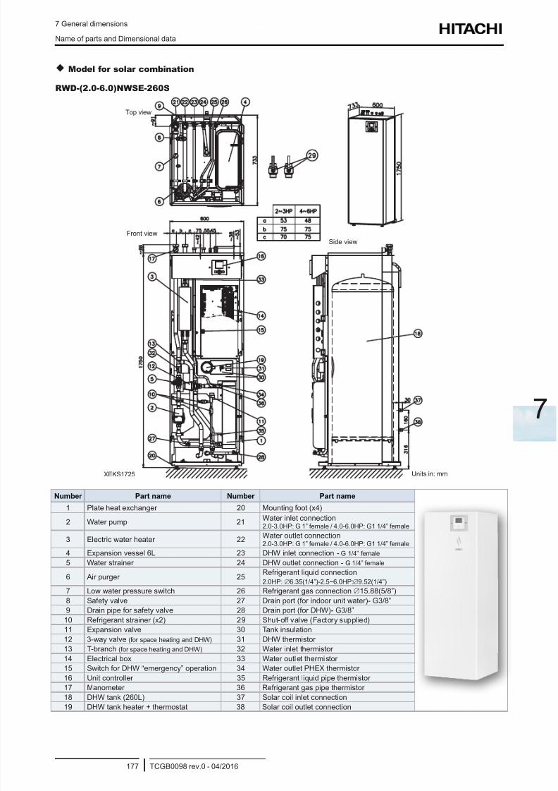
8/16/2019 Hitachi Yutaki Series 2016 Αντλίες θερμότητας
http://slidepdf.com/reader/full/hitachi-yutaki-series-2016- 187/256
7 General dimensions
Name of parts and Dimensional data
TCGB0098 rev.0 - 04/2016177
7
Model for solar combination
RWD-(2.0-6.0)NWSE-260S
Top view
Front view
Side view
Units in: mmXEKS1725
Number Part name Number Part name
1 Plate heat exchanger 20 Mounting foot (x4)
2 Water pump 21Water inlet connection2.0-3.0HP: G 1” female / 4.0-6.0HP: G1 1/4” female
3 Electric water heater 22Water outlet connection2.0-3.0HP: G 1” female / 4.0-6.0HP: G1 1/4” female
4 Expansion vessel 6L 23 DHW inlet connection - G 1/4” female5 Water strainer 24 DHW outlet connection - G 1/4” female
6 Air purger 25Refrigerant liquid connection
2.0HP:∅6.35(1/4”)-2.5~6.0HP:∅9.52(1/4”)
7 Low water pressure switch 26 Refrigerant gas connection ∅15.88(5/8”)
8 Safety valve 27 Drain port (for indoor unit water)- G3/8”
9 Drain pipe for safety valve 28 Drain port (for DHW)- G3/8”
10 Refrigerant strainer (x2) 29 Shut-off valve (Factory supplied)
11 Expansion valve 30 Tank insulation
12 3-way valve (for space heating and DHW) 31 DHW thermistor
13 T-branch (for space heating and DHW) 32 Water inlet thermistor
14 Electrical box 33 Water outlet thermistor
15 Switch for DHW “emergency” operation 34 Water outlet PHEX thermistor
16 Unit controller 35 Refrigerant liquid pipe thermistor
17 Manometer 36 Refrigerant gas pipe thermistor
18 DHW tank (260L) 37 Solar coil inlet connection
19 DHW tank heater + thermostat 38 Solar coil outlet connection
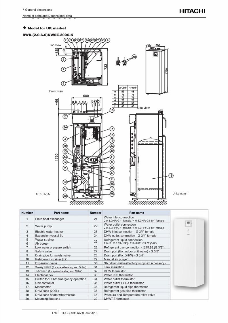
8/16/2019 Hitachi Yutaki Series 2016 Αντλίες θερμότητας
http://slidepdf.com/reader/full/hitachi-yutaki-series-2016- 188/256
7 General dimensions
Name of parts and Dimensional data
TCGB0098 rev.0 - 04/2016178
Model for UK market
RWD-(2.0-6.0)NWSE-200S-K
Units in: mm
Front view
Top view
Side view
XEKS1755
Number Part name Number Part name
1 Plate heat exchanger 21Water inlet connection2.0-3.0HP: G 1” female / 4.0-6.0HP: G1 1/4” female
2 Water pump 22Water outlet connection2.0-3.0HP: G 1” female / 4.0-6.0HP: G1 1/4” female
3 Electric water heater 23 DHW inlet connection - G 3/4” female
4 Expansion vessel 6L 24 DHW outlet connection - G 3/4” female
5 Water strainer 25
Refrigerant liquid connection2.0HP:∅ 6.35 (1/4”) / 2.5~6HP:∅9.52 (3/8”)6 Air purger
7 Low water pressure switch 26 Refrigerant gas connection - ∅15.88 (G 3/8”)
8 Safety valve 27 Drain port (For indoor unit water) - G 3/8”
9 Drain pipe for safety valve 28 Drain port (For DHW) - G 3/8”
10 Refrigerant strainer (x2) 29 Manual air purger
11 Expansion valve 30 Shutdown valve (Factory supplied accessory)
12 3-way valve (for space heating and DHW) 31 Tank insulation
13 T-branch (for space heating and DHW) 32 DHW thermistor
14 Electrical box 33 Water inlet thermistor
15 Switch for DHW emergency operation 34 Water outlet thermistor
16 Unit controller 35 Water outlet PHEX thermistor 17 Manometer 36 Refrigerant liquid pipe thermistor
18 DHW tank (200L) 37 Refrigerant gas pipe thermistor
19 DHW tank heater+thermostat 38 Pressure and Temperature relief valve
20 Mounting foot (x4) 39 DHWT Thermostat
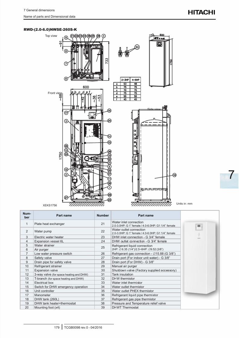
8/16/2019 Hitachi Yutaki Series 2016 Αντλίες θερμότητας
http://slidepdf.com/reader/full/hitachi-yutaki-series-2016- 189/256
7 General dimensions
Name of parts and Dimensional data
TCGB0098 rev.0 - 04/2016179
7
RWD-(2.0-6.0)NWSE-260S-K
Top view
Front view
Side view
XEKS1756Units in: mm
Num-
ber Part name Number Part name
1 Plate heat exchanger 21Water inlet connection2.0-3.0HP: G 1” female / 4.0-6.0HP: G1 1/4” female
2 Water pump 22Water outlet connection2.0-3.0HP: G 1” female / 4.0-6.0HP: G1 1/4” female
3 Electric water heater 23 DHW inlet connection - G 3/4” female4 Expansion vessel 6L 24 DHW outlet connection - G 3/4” female
5 Water strainer 25
Refrigerant liquid connection2HP:∅ 6.35 (1/4”)/2.5~6HP:∅9.52 (3/8”)6 Air purger
7 Low water pressure switch 26 Refrigerant gas connection - ∅15.88 (G 3/8”)
8 Safety valve 27 Drain port (For indoor unit water) - G 3/8”
9 Drain pipe for safety valve 28 Drain port (For DHW) - G 3/8”
10 Refrigerant strainer 29 Manual air purger
11 Expansion valve 30 Shutdown valve (Factory supplied accessory)
12 3-way valve (for space heating and DHW) 31 Tank insulation
13 T-branch (for space heating and DHW) 32 DHW thermistor
14 Electrical box 33 Water inlet thermistor
15 Switch for DHW emergency operation 34 Water outlet thermistor
16 Unit controller 35 Water outlet PHEX thermistor
17 Manometer 36 Refrigerant liquid pipe thermistor 18 DHW tank (260L) 37 Refrigerant gas pipe thermistor
19 DHW tank heater+thermostat 38 Pressure and Temperature relief valve
20 Mounting foot (x4) 39 DHWT Thermostat
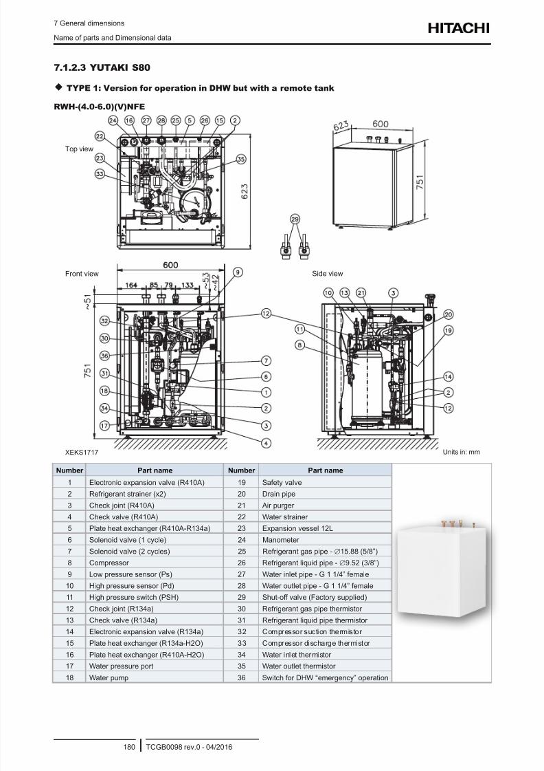
8/16/2019 Hitachi Yutaki Series 2016 Αντλίες θερμότητας
http://slidepdf.com/reader/full/hitachi-yutaki-series-2016- 190/256
7 General dimensions
Name of parts and Dimensional data
TCGB0098 rev.0 - 04/2016180
7.1.2.3 YUTAKI S80
TYPE 1: Version for operation in DHW but with a remote tank
RWH-(4.0-6.0)(V)NFE
Top view
Front view Side view
Units in: mmXEKS1717
Number Part name Number Part name
1 Electronic expansion valve (R410A) 19 Safety valve
2 Refrigerant strainer (x2) 20 Drain pipe
3 Check joint (R410A) 21 Air purger
4 Check valve (R410A) 22 Water strainer
5 Plate heat exchanger (R410A-R134a) 23 Expansion vessel 12L
6 Solenoid valve (1 cycle) 24 Manometer 7 Solenoid valve (2 cycles) 25 Refrigerant gas pipe - ∅15.88 (5/8”)
8 Compressor 26 Refrigerant liquid pipe - ∅9.52 (3/8”)
9 Low pressure sensor (Ps) 27 Water inlet pipe - G 1 1/4” female
10 High pressure sensor (Pd) 28 Water outlet pipe - G 1 1/4” female
11 High pressure switch (PSH) 29 Shut-off valve (Factory supplied)
12 Check joint (R134a) 30 Refrigerant gas pipe thermistor
13 Check valve (R134a) 31 Refrigerant liquid pipe thermistor
14 Electronic expansion valve (R134a) 32 Compressor suction thermistor
15 Plate heat exchanger (R134a-H2O) 33 Compressor discharge thermistor
16 Plate heat exchanger (R410A-H2O) 34 Water inlet thermistor
17 Water pressure port 35 Water outlet thermistor
18 Water pump 36 Switch for DHW “emergency” operation
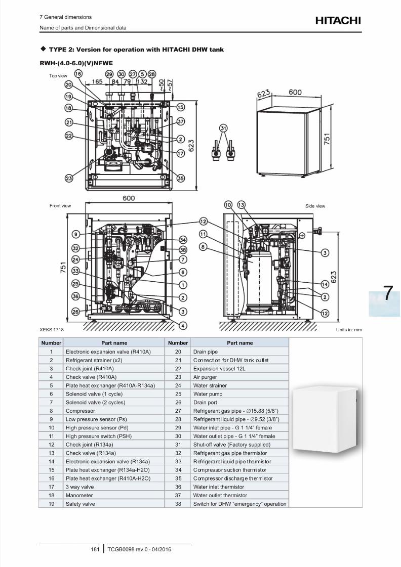
8/16/2019 Hitachi Yutaki Series 2016 Αντλίες θερμότητας
http://slidepdf.com/reader/full/hitachi-yutaki-series-2016- 191/256
7 General dimensions
Name of parts and Dimensional data
TCGB0098 rev.0 - 04/2016181
7
TYPE 2: Version for operation with HITACHI DHW tank
RWH-(4.0-6.0)(V)NFWE
Top view
Front view Side view
Units in: mmXEKS 1718
Number Part name Number Part name
1 Electronic expansion valve (R410A) 20 Drain pipe
2 Refrigerant strainer (x2) 21 Connection for DHW tank outlet
3 Check joint (R410A) 22 Expansion vessel 12L
4 Check valve (R410A) 23 Air purger
5 Plate heat exchanger (R410A-R134a) 24 Water strainer
6 Solenoid valve (1 cycle) 25 Water pump
7 Solenoid valve (2 cycles) 26 Drain port
8 Compressor 27 Refrigerant gas pipe - ∅15.88 (5/8”)
9 Low pressure sensor (Ps) 28 Refrigerant liquid pipe - ∅9.52 (3/8”)
10 High pressure sensor (Pd) 29 Water inlet pipe - G 1 1/4” female
11 High pressure switch (PSH) 30 Water outlet pipe - G 1 1/4” female
12 Check joint (R134a) 31 Shut-off valve (Factory supplied)
13 Check valve (R134a) 32 Refrigerant gas pipe thermistor
14 Electronic expansion valve (R134a) 33 Refrigerant liquid pipe thermistor
15 Plate heat exchanger (R134a-H2O) 34 Compressor suction thermistor
16 Plate heat exchanger (R410A-H2O) 35 Compressor discharge thermistor
17 3 way valve 36 Water inlet thermistor
18 Manometer 37 Water outlet thermistor 19 Safety valve 38 Switch for DHW “emergency” operation
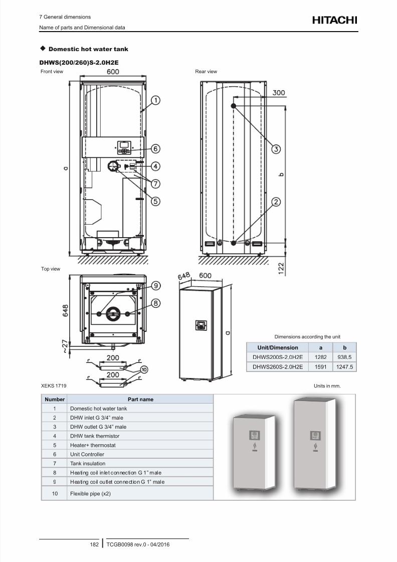
8/16/2019 Hitachi Yutaki Series 2016 Αντλίες θερμότητας
http://slidepdf.com/reader/full/hitachi-yutaki-series-2016- 192/256
7 General dimensions
Name of parts and Dimensional data
TCGB0098 rev.0 - 04/2016182
Domestic hot water tank
DHWS(200/260)S-2.0H2E
Front view Rear view
Top view
Unit/Dimension a b
DHWS200S-2.0H2E 1282 938.5
DHWS260S-2.0H2E 1591 1247.5
Dimensions according the unit
Units in mm.XEKS 1719
Number Part name
1 Domestic hot water tank
2 DHW inlet G 3/4” male
3 DHW outlet G 3/4” male
4 DHW tank thermistor
5 Heater+ thermostat
6 Unit Controller
7 Tank insulation
8 Heating coil inlet connection G 1” male
9 Heating coil outlet connection G 1” male
10 Flexible pipe (x2)
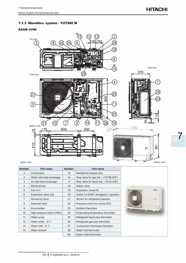
8/16/2019 Hitachi Yutaki Series 2016 Αντλίες θερμότητας
http://slidepdf.com/reader/full/hitachi-yutaki-series-2016- 193/256
7 General dimensions
Name of parts and Dimensional data
TCGB0098 rev.0 - 04/2016183
7
7.1.3 Monobloc system - YUTAKI M
RASM-3VNE
Front view
Top view
Bottom view
Side view
Units in mm.XEKS 1720
Number Part name Number Part name
1 Compressor 15 Refrigerant strainer (x4)
2 Water side heat exchanger 16 Stop valve for gas line -∅15.88 (5/8”)
3 Air side heat exchanger 17 Stop valve for liquid line -∅9.52 (3/8”)
4 Electrical box 18 Safety valve
5 Fan (x1) 19 Expansion vessel 6L
6 Expansion valve (x2) 20 Switch for DHW “emergency” operation
7 Reversing valve 21 Sensor for refrigerant pressure
8 Solenoid valve 22 Pressure switch for control (Pd)
9 Accumulator 23 Ambient thermistor
10 High pressure switch (PSH) 24 Evaporating temperature thermistor
11 Water pump 25 Refrigerant liquid pipe thermistor
12 Water outlet - G 1” 26 Refrigerant gas pipe thermistor
13 Water inlet - G 1” 27 Compressor discharge thermistor
14 Water strainer 28 Water inlet thermistor
29 Water outlet thermistor
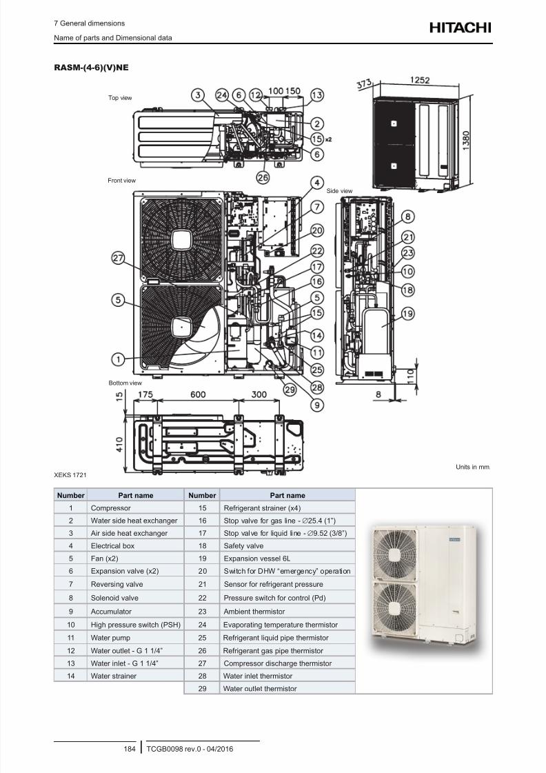
8/16/2019 Hitachi Yutaki Series 2016 Αντλίες θερμότητας
http://slidepdf.com/reader/full/hitachi-yutaki-series-2016- 194/256
7 General dimensions
Name of parts and Dimensional data
TCGB0098 rev.0 - 04/2016184
RASM-(4-6)(V)NE
Front view
Top view
Bottom view
Side view
Units in mm.
XEKS 1721
Number Part name Number Part name
1 Compressor 15 Refrigerant strainer (x4)
2 Water side heat exchanger 16 Stop valve for gas line -∅25.4 (1”)
3 Air side heat exchanger 17 Stop valve for liquid line -∅9.52 (3/8”)
4 Electrical box 18 Safety valve
5 Fan (x2) 19 Expansion vessel 6L
6 Expansion valve (x2) 20 Switch for DHW “emergency” operation
7 Reversing valve 21 Sensor for refrigerant pressure
8 Solenoid valve 22 Pressure switch for control (Pd)
9 Accumulator 23 Ambient thermistor
10 High pressure switch (PSH) 24 Evaporating temperature thermistor
11 Water pump 25 Refrigerant liquid pipe thermistor
12 Water outlet - G 1 1/4” 26 Refrigerant gas pipe thermistor
13 Water inlet - G 1 1/4” 27 Compressor discharge thermistor
14 Water strainer 28 Water inlet thermistor 29 Water outlet thermistor
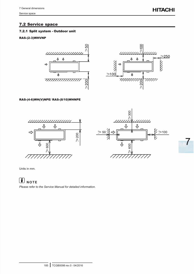
8/16/2019 Hitachi Yutaki Series 2016 Αντλίες θερμότητας
http://slidepdf.com/reader/full/hitachi-yutaki-series-2016- 195/256
7 General dimensions
Service space
TCGB0098 rev.0 - 04/2016185
7
7.2 Service space
7.2.1 Split system - Outdoor unit
RAS-(2-3)WHVNP
RAS-(4-6)WH(V)NPE/ RAS-(8/10)WHNPE
Units in mm.
N O T E
Please refer to the Service Manual for detailed information.
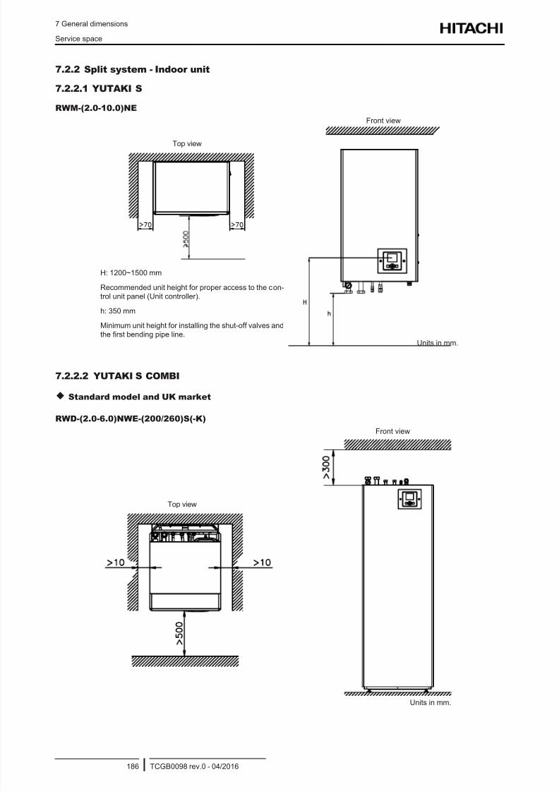
8/16/2019 Hitachi Yutaki Series 2016 Αντλίες θερμότητας
http://slidepdf.com/reader/full/hitachi-yutaki-series-2016- 196/256
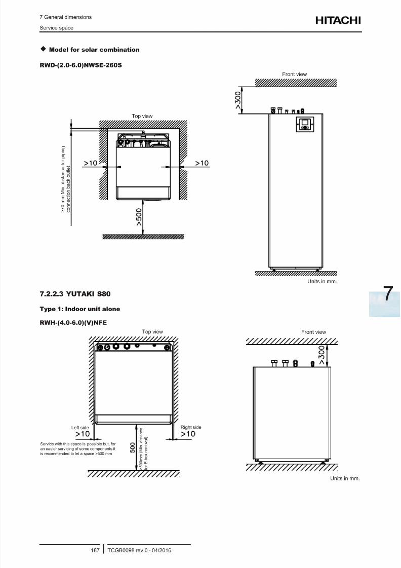
8/16/2019 Hitachi Yutaki Series 2016 Αντλίες θερμότητας
http://slidepdf.com/reader/full/hitachi-yutaki-series-2016- 197/256
7 General dimensions
Service space
TCGB0098 rev.0 - 04/2016187
7
Model for solar combination
RWD-(2.0-6.0)NWSE-260S
Units in mm.
Front view
Top view
> 7 0 m m
M i n .
d i s t a n c e f o r p i p i n g
c o n n e c
t i o n b a c k o u t l e t
7.2.2.3 YUTAKI S80
Type 1: Indoor unit alone
RWH-(4.0-6.0)(V)NFE
Units in mm.
Service with this space is possible but, foran easier servicing of some components it
is recommended to let a space >500 mm
Left side Right side
> 5 0 0 m m ( M i n .
d i s t a n c e
f o r E - b o x r e m o v a l )
Top view Front view
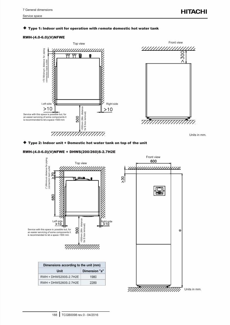
8/16/2019 Hitachi Yutaki Series 2016 Αντλίες θερμότητας
http://slidepdf.com/reader/full/hitachi-yutaki-series-2016- 198/256
7 General dimensions
Service space
TCGB0098 rev.0 - 04/2016188
Type 1: Indoor unit for operation with remote domestic hot water tank
RWH-(4.0-6.0)(V)NFWE
Top view Front view
Units in mm.
Right sideLeft side
Service with this space is possible but, foran easier servicing of some components it
is recommended to let a space >500 mm
> 5 0 0 m m ( M i n . d
i s t a n c e
f o r E - b o x r e m o v a
l )
> 7 0 M i n i m u m
d i s t a n c e f o
r p i p i n g
c o n n e c t i o n b a c k o u t l e t
Type 2: Indoor unit + Domestic hot water tank on top of the unit
RWH-(4.0-6.0)(V)NFWE + DHWS(200/260)S-2.7H2E
Service with this space is possible but, for
an easier servicing of some components itis recommended to let a space >500 mm
Units in mm.
Top view
Left side
Front view
Right side
> 5 0 0 m m ( M i n .
d i s t a n c e
f o r E - b o x r e m o
v a l )
( * ) M i n i m u m d i s t a n
c e f o r p i p i n g
c o n n e c t i o n b a c k o u t l e t
Dimensions according to the unit (mm)
Unit Dimension "a"
RWH + DHWS200S-2.7H2E 1980
RWH + DHWS260S-2.7H2E 2289
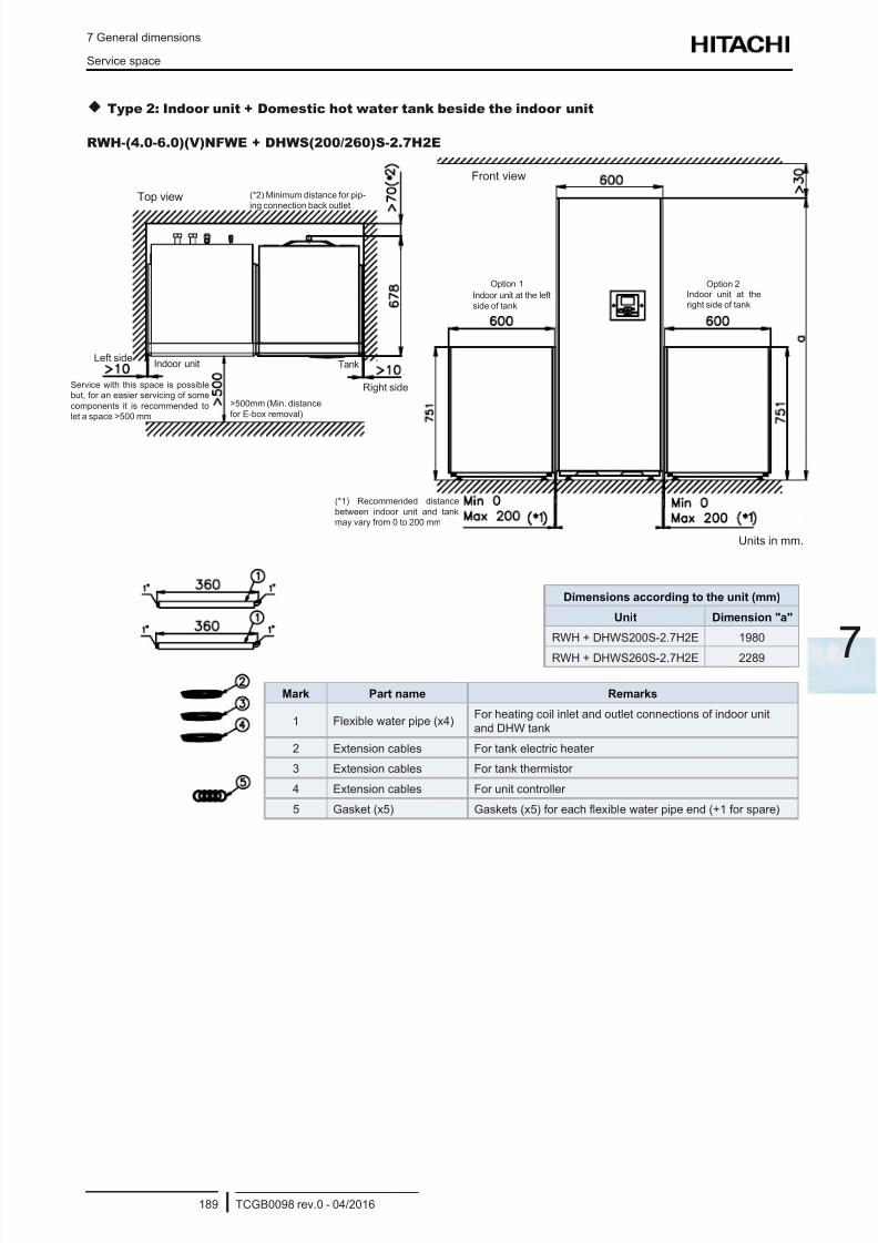
8/16/2019 Hitachi Yutaki Series 2016 Αντλίες θερμότητας
http://slidepdf.com/reader/full/hitachi-yutaki-series-2016- 199/256
7 General dimensions
Service space
TCGB0098 rev.0 - 04/2016189
7
Type 2: Indoor unit + Domestic hot water tank beside the indoor unit
RWH-(4.0-6.0)(V)NFWE + DHWS(200/260)S-2.7H2E
Units in mm.
Mark Part name Remarks
1 Flexible water pipe (x4)For heating coil inlet and outlet connections of indoor unit
and DHW tank
2 Extension cables For tank electric heater
3 Extension cables For tank thermistor
4 Extension cables For unit controller
5 Gasket (x5) Gaskets (x5) for each exible water pipe end (+1 for spare)
Top view
Left side
Front view
Right side
>500mm (Min. distance
for E-box removal)
(*2) Minimum distance for pip-ing connection back outlet
Dimensions according to the unit (mm)
Unit Dimension "a"
RWH + DHWS200S-2.7H2E 1980
RWH + DHWS260S-2.7H2E 2289
(*1) Recommended distance
between indoor unit and tankmay vary from 0 to 200 mm
Option 1 Option 2
Indoor unit at the left
side of tank
Indoor unit at theright side of tank
Indoor unit Tank
Service with this space is possiblebut, for an easier servicing of some
components it is recommended tolet a space >500 mm
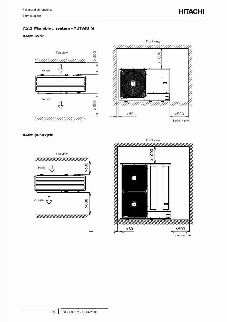
8/16/2019 Hitachi Yutaki Series 2016 Αντλίες θερμότητας
http://slidepdf.com/reader/full/hitachi-yutaki-series-2016- 200/256
7 General dimensions
Service space
TCGB0098 rev.0 - 04/2016190
7.2.3 Monobloc system - YUTAKI M
RASM-3VNE
Units in mm.
Top view
Front view
Air inlet
Air outlet
RASM-(4-6)(V)NE
Units in mm.
Top view
Front view
Air inlet
Air outlet
8/16/2019 Hitachi Yutaki Series 2016 Αντλίες θερμότητας
http://slidepdf.com/reader/full/hitachi-yutaki-series-2016- 201/256
8 Refrigerant cycle and hydraulic circuit
TCGB0098 rev.0 - 04/2016191
8
Index
8.1 Refrigerant cycle and hydraulic circuit for Split system ....................................................................... 192
8.1.1 YUTAKI S .................................................................................................................................................... 192
8.1.2 YUTAKI S COMBI........................................................................................................................................195
8.1.3 YUTAKI S80 ................................................................................................................................................ 197
8.1.3.1 Indoor unit standalone version....................................................................................................197
8.1.3.2 Indoor unit for integrated tank version ........................................................................................198
8.2 Refrigerant cycle and hydraulic circuit for Monobloc system - YUTAKI M .......................................... 199
8 . R e f r i g e ra n t c y c l e a n d h y d ra u l i c c i r c u i t
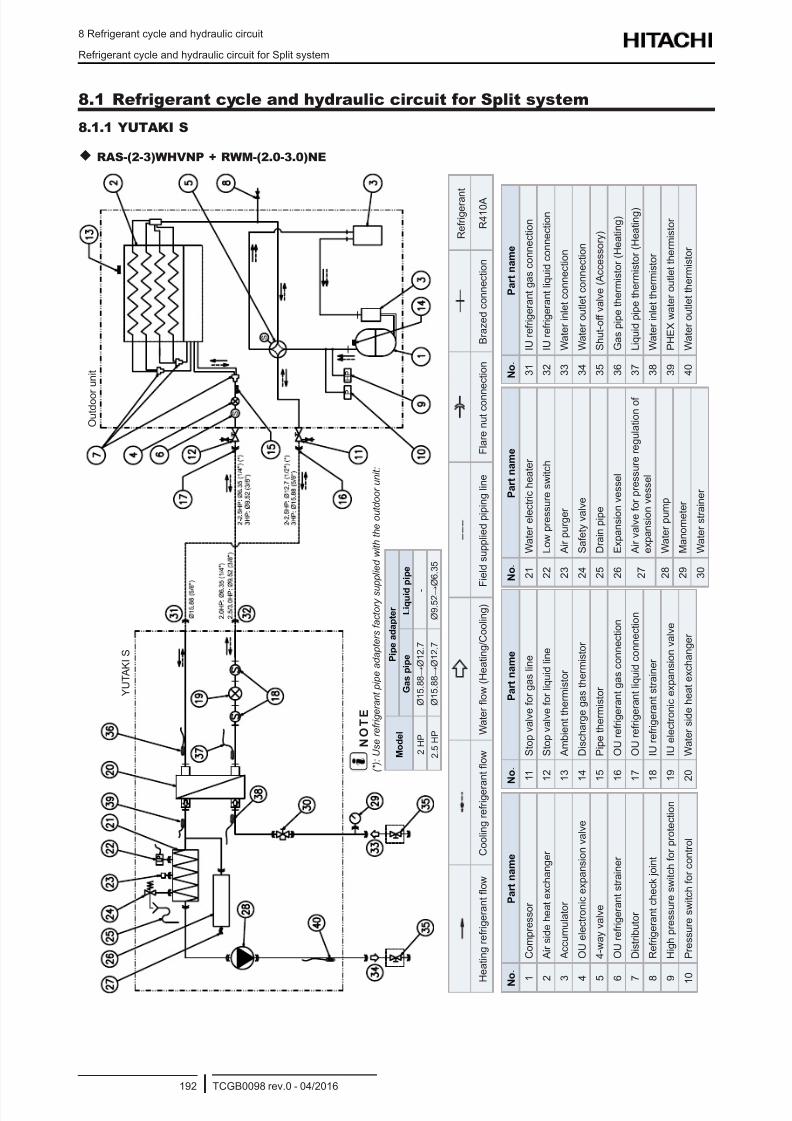
8/16/2019 Hitachi Yutaki Series 2016 Αντλίες θερμότητας
http://slidepdf.com/reader/full/hitachi-yutaki-series-2016- 202/256
8 Refrigerant cycle and hydraulic circuit
Refrigerant cycle and hydraulic circuit for Split system
TCGB0098 rev.0 - 04/2016192
8.1 Refrigerant cycle and hydraulic circuit for Split system
8.1.1 YUTAKI S
RAS-(2-3)WHVNP + RWM-(2.0-3.0)NE
R e f r i g e r a n
t
H e a t i n g r e f r i g e r a n t o w
C o o l i n g r e f r i g e r a
n t o w
W a t e r o w ( H e a t i n g / C o o l i n g )
F i e l d s u p p l i e d p i p i n g l i n e
F l a r e n u t c o n n
e c t i o n
B r a z e d c o n n e c t i o n
R 4 1 0 A
N
o .
P a r t n a m e
1
C o m p r e s s o r
2
A i r s i d e h e a t e x c h a n g e r
3
A c c u m u l a t o r
4
O U e l e c t r o n i c e x p a n s i o n v a l v e
5
4 - w a y v a l v e
6
O U r e f r i g e r a n t s t r a i n e r
7
D i s t r i b u t o r
8
R e f r i g e r a n t c h e c k j o i n t
9
H i g h p r e s s u r e s w i t c h f o r p r o t e c t i o n
1
0
P r e s s u r e s w i t c h f o r c o n t r o l
N o .
P a r t n a m e
1 1
S t o p v a l v e f o r g a s l i n e
1 2
S t o p v a l v e f o r l i q u i d l i n e
1 3
A m b i e n t t h e r m i s t o r
1 4
D i s c h a r g e g a s t h e r m i s t o r
1 5
P i p e t h e r m i s t o r
1 6
O U r e f r i g e r a n t g a s c o n n e c t i o n
1 7
O U r e f r i g e r a n t l i q u i d c o n n e c t i o n
1 8
I U r e f r i g e r a n t s t r a i n e r
1 9
I U e l e c t r o n i c e x p a n s i o n v a l v e
2 0
W a t e r s i d e h e a t e x c h a n g e r
N o .
P a r t n a m e
2 1
W a t e r e l e c t r i c h e a t e r
2 2
L o w p r e s s u r e s w i t c h
2 3
A i r p u r g e r
2 4
S a f e t y v a l v e
2 5
D r a i n p i p e
2 6
E x p a n s i o n v e s s e l
2 7
A i r v a l v e f o r p r e s s u r e r e g u l a t i o n o f
e x p a n s i o n v e s s e l
2 8
W a t e r p u m p
2 9
M a n o m e t e r
3 0
W a t e r s t r a i n e r
N o .
P a r t n a m e
3 1
I U r e f r i g e r a n t g a s c o n n e c t i o n
3 2
I U r e f r i g e r a n t l i q u i d c o n n e c t i o n
3 3
W a t e r i n l e t c o n n e c t i o n
3 4
W a t e r o u t l e t c o n n e c t i o n
3 5
S h u t - o f f v a l v e ( A c c e s s o r y )
3 6
G a s p i p e t h e r m i s t o r ( H e a t i n g )
3 7
L i q u i d p i p e t h e r m i s t o r ( H e a t i n g )
3 8
W a t e r i n l e t t h e r m i s t o r
3 9
P H E X w a t e r o u t l e t t h e r m i s t o r
4 0
W a t e r o u t l e t t h e r m i s t o r
O u t d o o r
u n i t
Y U T A K I S
N O T E
( * ) : U s e r e f r i g e r a n t p i p e a d a p t e r s f a c t o r y s u
p p l i e d w i t h t h e o u t d o o r u n i t :
M o d e l
P i p e a d a p t e r
G a s p i p e
L i q u i d
p i p e
2 H P
Ø 1 5 . 8 8 → Ø 1 2 . 7
-
2 . 5 H P
Ø 1 5 . 8 8 → Ø 1 2 . 7
Ø 9 . 5 2 →
Ø 6 . 3 5
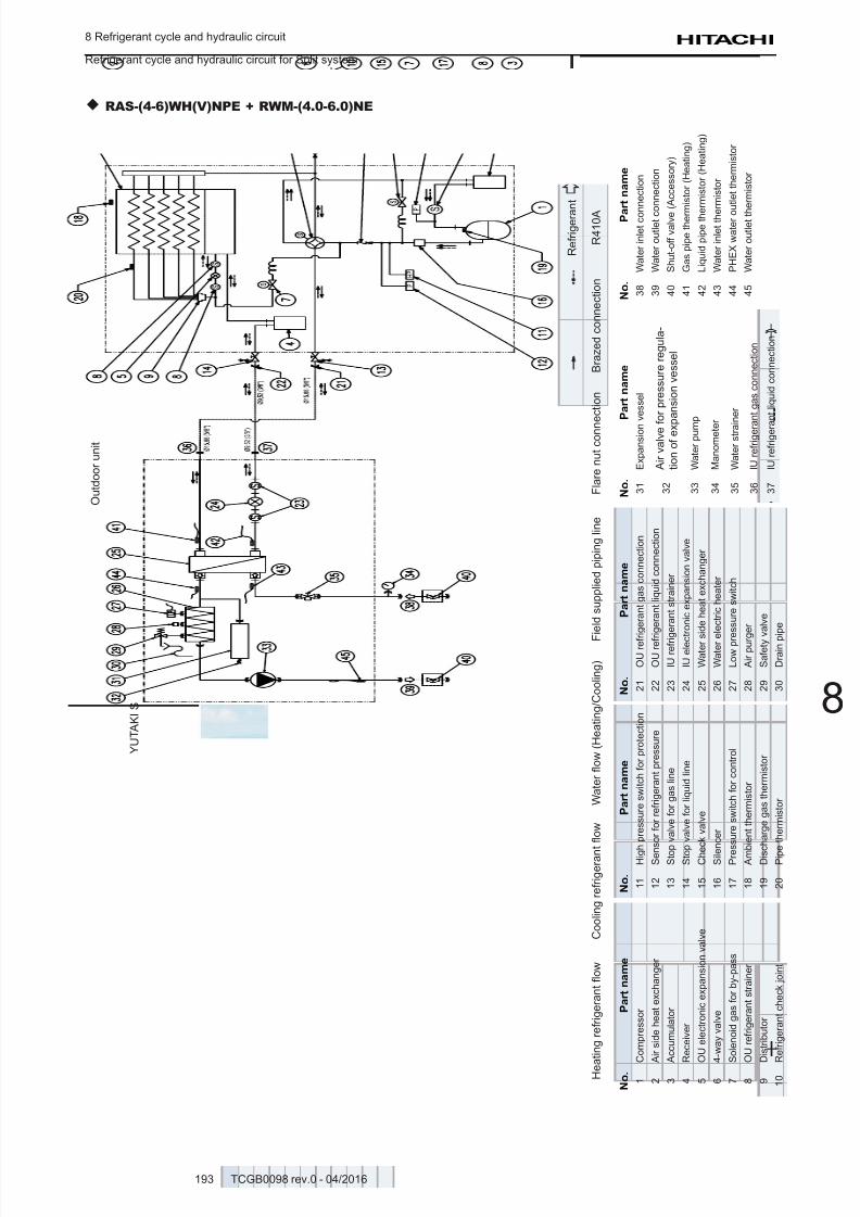
8/16/2019 Hitachi Yutaki Series 2016 Αντλίες θερμότητας
http://slidepdf.com/reader/full/hitachi-yutaki-series-2016- 203/256
8 Refrigerant cycle and hydraulic circuit
Refrigerant cycle and hydraulic circuit for Split system
TCGB0098 rev.0 - 04/2016193
8
RAS-(4-6)WH(V)NPE + RWM-(4.0-6.0)NE
N o .
P a r t n a m e
1
C o m p r e s s o r
2
A i r s i d e h e a t e x c h a n g e r
3
A c c u m u l a t o r
4
R e c e i v e r
5
O U e l e c t r o n i c e x p a n s i o n v a l v e
6
4 - w a y v a l v e
7
S o l e n o i d g a s f o r b y - p a s s
8
O U r e f r i g e r a n t s t r a i n e r
9
D i s t r i b u t o r
1 0
R e f r i g e r a n t c h e c k j o i n t
N o .
P a r t n a m e
1 1
H i g
h p r e s s u r e s w i t c h f o r p r o t e c t i o n
1 2
S e n
s o r f o r r e f r i g e r a n t p r e s s u r e
1 3
S t o p v a l v e f o r g a s l i n e
1 4
S t o p v a l v e f o r l i q u i d l i n e
1 5
C h e c k v a l v e
1 6
S i l e
n c e r
1 7
P r e
s s u r e s w i t c h f o r c o n t r o l
1 8
A m b i e n t t h e r m i s t o r
1 9
D i s c h a r g e g a s t h e r m i s t o r
2 0
P i p e t h e r m i s t o r
N o .
P a r t n a m e
2 1
O U r e f r i g e r a n t g a s c o n n e c t i o n
2 2
O U r e f r i g e r a n t l i q u i d c o n n e c t i o n
2 3
I U r e f r i g e r a n t s t r a i n e r
2 4
I U e l e c
t r o n i c e x p a n s i o n v a l v e
2 5
W a t e r s i d e h e a t e x c h a n g e r
2 6
W a t e r e l e c t r i c h e a t e r
2 7
L o w p r e s s u r e s w i t c h
2 8
A i r p u r g e r
2 9
S a f e t y
v a l v e
3 0
D r a i n p
i p e
N o .
P a r t n a m e
3 1
E x p a n s i o n
v e s s e l
3 2
A i r v a l v e f o r p r e s s u r e r e g u l a -
t i o n o f e x p a n s i o n v e s s e l
3 3
W a t e r p u m
p
3 4
M a n o m e t e
r
3 5
W a t e r s t r a i n e r
3 6
I U r e f r i g e r a n t g a s c o n n e c t i o n
3 7
I U r e f r i g e r a n t l i q u i d c o n n e c t i o n
N o .
P a
r t n a m e
3 8
W a t e r i n l e t c o n n e c t i o n
3 9
W a t e r o u t l e t c o n n e c t i o n
4 0
S h u t - o f f v a l v e
( A c c e s s o r y )
4 1
G a s p i p e t h e r m i s t o r ( H e a t i n g )
4 2
L i q u i d p i p e t h e
r m i s t o r ( H e a t i n g )
4 3
W a t e r i n l e t t h e
r m i s t o r
4 4
P H E X w a t e r o
u t l e t t h e r m i s t o r
4 5
W a t e r o u t l e t t h
e r m i s t o r
R e f r i g e r a
n t
H e a t i n g r e f r i g e r a n t o w
C o o l i n g r e f r i g e r a n
t o w
W a t e r o w ( H e a t i n g / C o o l i n g )
F
i e l d s u p p l i e d p i p i n g l i n e
F l a r e n u t c o n n
e c t i o n
B r a z e d c o n n e c t i o n
R 4 1 0 A
O u t d o o r u n i t
Y U T A K I S
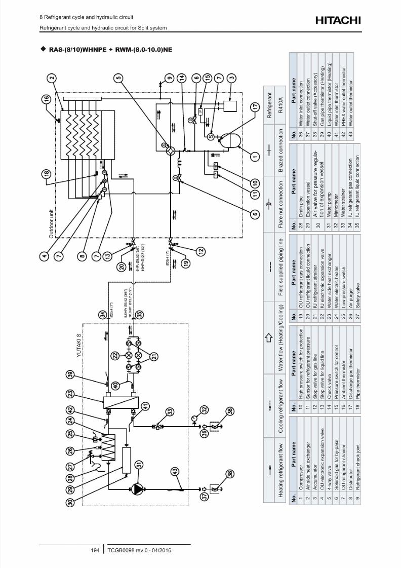
8/16/2019 Hitachi Yutaki Series 2016 Αντλίες θερμότητας
http://slidepdf.com/reader/full/hitachi-yutaki-series-2016- 204/256
8 Refrigerant cycle and hydraulic circuit
Refrigerant cycle and hydraulic circuit for Split system
TCGB0098 rev.0 - 04/2016194
RAS-(8/10)WHNPE + RWM-(8.0-10.0)NE
N o
.
P a r t n a m e
1
C o m p r e s s o r
2
A i r s i d e h e a t e x c h a n g e r
3
A c c u m u l a t o r
4
O U e l e c t r o n i c e x p a n s i o n v a l v e
5
4 - w a y v a l v e
6
S o l e n o i d g a s f o r b y - p a s s
7
O U r e f r i g e r a n t s t r a i n e r
8
D i s t r i b u t o r
9
R e f r i g e r a n t c h e c k j o i n t
N o .
P a r t n a m e
1 0 H
i g h p r e s s u r e s w i t c h f o r p r o t e c t i o n
1 1 S
e n s o r f o r r e f r i g e r a n t p r e s s u r e
1 2 S
t o p v a l v e f o r g a s l i n e
1 3 S
t o p v a l v e f o r l i q u i d l i n e
1 4 C
h e c k v a l v e
1 5 P
r e s s u r e s w i t c h f o r c o n t r o l
1 6 A
m b i e n t t h e r m i s t o r
1 7 D
i s c h a r g e g a s t h e r m i s t o r
1 8 P
i p e t h e r m i s t o r
N o .
P a r t n a m e
1 9
O U r e f r i g e r a n t g a s c o n n e c t i o n
2 0
O U r e f r i g e r a n t l i q u i d c o n n e c t i o n
2 1
I U r e f r i g e r a n t s t r a i n e r
2 2
I U e l e
c t r o n i c e x p a n s i o n v a l v e
2 3
W a t e r s i d e h e a t e x c h a n g e r
2 4
W a t e r e l e c t r i c h e a t e r
2 5
L o w p r e s s u r e s w i t c h
2 6
A i r p u
r g e r
2 7
S a f e t y v a l v e
N o .
P a r t n a m e
2 8
D r a i n p i p e
2 9
E x p a n s i o n v e s s e l
3 0
A i r v a l v e
f o r p r e s s u r e r e g u l a -
t i o n o f e x p a n s i o n v e s s e l
3 1
W a t e r p u m p
3 2
M a n o m e t e r
3 3
W a t e r s t r a i n e r
3 4
I U r e f r i g e r a n t g a s c o n n e c t i o n
3 5
I U r e f r i g e r a n t l i q u i d c o n n e c t i o n
N o .
P a
r t n a m e
3 6
W a t e r i n l e t c o n n e c t i o n
3 7
W a t e r o u t l e t c o n n e c t i o n
3 8
S h u t - o f f v a l v e
( A c c e s s o r y )
3 9
G a s p i p e t h e r m i s t o r ( H e a t i n g )
4 0
L i q u i d p i p e t h e r m i s t o r ( H e a t i n g )
4 1
W a t e r i n l e t t h e
r m i s t o r
4 2
P H E X w a t e r o
u t l e t t h e r m i s t o r
4 3
W a t e r o u t l e t t h e r m i s t o r
R e f r i g e r a
n t
H e a t i n g r e f r i g e r a n t o w
C o o l i n g r e f r i g e r a n t o w
W a t e r o w ( H e a t i n g / C o o l i n g )
F i e l d s u p p l i e d p i p i n g l i n e
F l a r e n u t c o n n e c t i o n
B r a z e d c o n n e c t i o n
R 4 1 0 A
O u t d o o r u n i t
Y U T A K I S
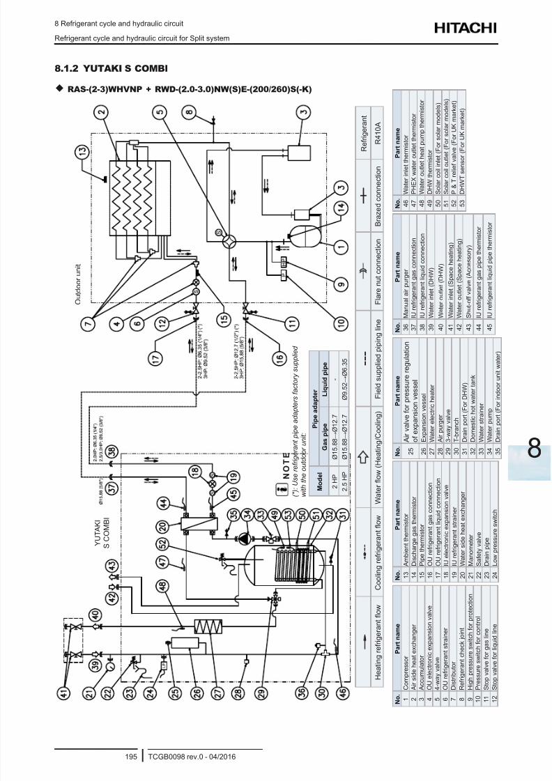
8/16/2019 Hitachi Yutaki Series 2016 Αντλίες θερμότητας
http://slidepdf.com/reader/full/hitachi-yutaki-series-2016- 205/256
8 Refrigerant cycle and hydraulic circuit
Refrigerant cycle and hydraulic circuit for Split system
TCGB0098 rev.0 - 04/2016195
8
8.1.2 YUTAKI S COMBI
RAS-(2-3)WHVNP + RWD-(2.0-3.0)NW(S)E-(200/260)S(-K)
N o .
P a r t n a m e
1
C o
m p r e s s o r
2
A i r
s i d e h e a t e x c h a n g e r
3
A c c u m u l a t o r
4
O U
e l e c t r o n i c e x p a n s i o n v a l v e
5
4 - w
a y v a l v e
6
O U
r e f r i g e r a n t s t r a i n e r
7
D i s
t r i b u t o r
8
R e
f r i g e r a n t c h e c k j o i n t
9
H i g h p r e s s u r e s w i t c h f o r p r o t e c t i o n
1 0
P r e s s u r e s w i t c h f o r c o n t r o l
1 1
S t o
p v a l v e f o r g a s l i n e
1 2
S t o
p v a l v e f o r l i q u i d l i n e
N o .
P a r t n a m e
1 3
A m b i e n
t t h e r m i s t o r
1 4
D i s c h a r g e g a s t h e r m i s t o r
1 5
P i p e t h e r m i s t o r
1 6
O U r e f r i g e r a n t g a s c o n n e c t i o n
1 7
O U r e f r i g e r a n t l i q u i d c o n n e c t i o n
1 8
I U e l e c t r o n i c e x p a n s i o n v a l v e
1 9
I U r e f r i g
e r a n t s t r a i n e r
2 0
W a t e r s
i d e h e a t e x c h a n g e r
2 1
M a n o m
e t e r
2 2
S a f e t y v a l v e
2 3
D r a i n p i p e
2 4
L o w p r e s s u r e s w i t c h
N o .
P a r t n a m e
2 5
A i r v a l v e f o
r p r e s s u r e r e g u l a t i o n
o f e x p a n s i o n v e s s e l
2 6
E x p a n s i o n v
e s s e l
2 7
W a t e r e l e c t r i c h e a t e r
2 8
A i r p u r g e r
2 9
3 - w a y v a l v e
3 0
T - b r a n c h
3 1
D r a i n p o r t ( F
o r D H W )
3 2
D o m e s t i c h o
t w a t e r t a n k
3 3
W a t e r s t r a i n e r
3 4
W a t e r p u m p
3 5
D r a i n p o r t ( F
o r i n d o o r u n i t w a t e r )
N o .
P a r
t n a m e
3 6
M a n u a l a i r p u r g e
r
3 7
I U r e f r i g e r a n t g a s c o n n e c t i o n
3 8
I U r e f r i g e r a n t l i q u
i d c o n n e c t i o n
3 9
W a t e r i n l e t ( D H W
)
4 0
W a t e r o u t l e t ( D H
W )
4 1
W a t e r i n l e t ( S p a c e h e a t i n g )
4 2
W a t e r o u t l e t ( S p a c e h e a t i n g )
4 3
S h u t - o f f v a l v e ( A c c e s s o r y )
4 4
I U r e f r i g e r a n t g a s p i p e t h e r m i s t o r
4 5
I U r e f r i g e r a n t l i q u
i d p i p e t h e r m i s t o r
N o .
P a r t n a m
e
4 6
W a t e r i n l e t t h e r m i s t o r
4 7
P H E X w a t e r o u t l e t t h e r m i s t o r
4 8
W a t e r o u t l e t h e a t p u m
p t h e r m i s t o r
4 9
D H W t
h e r m i s t o r
5 0
S o l a r c o i l i n l e t ( F o r s o
l a r m o d e l s )
5 1
S o l a r c o i l o u t l e t ( F o r s o l a r m o d e l s )
5 2
P & T r e l i e f v a l v e ( F o r U K m a r k e t )
5 3
D H W T s e n s o r ( F o r U K m a r k e t )
R e f r i g e r a n t
H e a t i n g r e f r i g e r a n t o w
C o o l i n g r e f r i g e r a n t o w
W a t e r o w ( H e a t i n g / C o o l i n g )
F i e l d s u p p l i e d p i p i n g l i n e
F l a r e n u t c
o n n e c t i o n
B r a z e d c o n n e c t i o n
R 4 1 0 A
O u t d o o r u n i t
Y U T A K I
S
C O M B I
N O T E
( * ) : U s e r e f r i g e r a n t p i p e a d a p
t e r s f a c t o r y s u p p l i e d
w i t h t h e o u t d o o r u n i t :
M o d e l
P i p e a d a p t e r
G a s p i p e
L i q u i d p i p e
2 H P
Ø 1 5 . 8 8 → Ø 1 2 . 7
-
2 . 5 H P
Ø 1 5 . 8 8 → Ø 1 2 . 7
Ø 9 . 5 2 → Ø 6 . 3 5
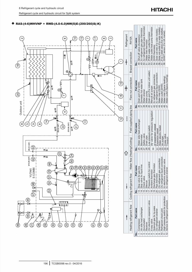
8/16/2019 Hitachi Yutaki Series 2016 Αντλίες θερμότητας
http://slidepdf.com/reader/full/hitachi-yutaki-series-2016- 206/256
8 Refrigerant cycle and hydraulic circuit
Refrigerant cycle and hydraulic circuit for Split system
TCGB0098 rev.0 - 04/2016196
RAS-(4-6)WHVNP + RWD-(4.0-6.0)NW(S)E-(200/260)S(-K)
O u t d o o r u n i t
Y U T A K I
S C O M B I
N o .
P a r t n a m e
1
C o m p r e s s o r
2
A i r s i d e h e a t e x c h a n g e r
3
A c c u m u l a t o r
4
R e c e i v e r
5
O U e l e c t r o n i c e x p a n s i o n v a l v e
6
4 - w a y v a l v e
7
S o l e n o i d g a s f o r b y - p a s s
8
O U r e f r i g e r a n t s t r a i n e r
9
D i s t r i b u t o r
1 0
R e f r i g e r a n t c h e c k j o i n t
1 1
H i g h p r e s s u r e s w i t c h f o r p r o t e c t i o n
1 2
S e n s o r f o r r e f r i g e r a n t p r e s s u r e
N o .
P a r t n a m e
1 3
S t o p v a l v e f o r g a s l i n e
1 4
S t o p v a l v e f o r l i q u i d l i n e
1 5
C h e c k v a l v e
1 6
S i l e n c e r
1 7
P r e s s u r e s w i t c h f o r c o n t r o l
1 8
A m b i e n t t h e r m i s t o r
1 9
D i s c h a r g e g a s t h e r m i s t o r
2 0
P i p e t h e r m i s t o r
2 1
O U r e f r i g e r a n t g a s c o n n e c t i o n
2 2
O U r e f r i g e r a n t l i q u i d c o n n e c t i o n
2 3
I U e l e c t r o n i c e x p a n s i o n v a l v e
2 4
I U r e f r i g e r a n t s t r a i n e r
N o .
P a r t n a m e
2 5
W a t e r s i d e h e a t e x c h a n g e r
2 6
M a n o m e t e r
2 7
S a f
e t y v a l v e
2 8
D r a
i n p i p e
2 9
L o w
p r e s s u r e s w i t c h
3 0
A i r
v a l v e f o r p r e s s u r e r e g u l a t i o n
o f e
x p a n s i o n v e s s e l
3 1
E x p
a n s i o n v e s s e l
3 2
W a t e r e l e c t r i c h e a t e r
3 3
A i r
p u r g e r
3 4
3 - w
a y v a l v e
3 5
T - b r a n c h
N o .
P a r t n a m e
3 6
D r a i n p o
r t ( F o r D H W )
3 7
D o m e s t i c h o t w a t e r t a n k
3 8
W a t e r s t r a i n e r
3 9
W a t e r p u
m p
4 0
D r a i n p o
r t ( F o r i n d o o r u n i t w a t e r )
4 1
M a n u a l a i r p u r g e r
4 2
I U r e f r i g e r a n t g a s c o n n e c t i o n
4 3
I U r e f r i g e r a n t l i q u i d c o n n e c t i o n
4 4
W a t e r i n l e t ( D H W )
4 5
W a t e r o u
t l e t ( D H W )
4 6
W a t e r i n l e t ( S p a c e h e a t i n g )
4 7
W a t e r o u
t l e t ( S p a c e h e a t i n g )
N o .
P
a r t n a m e
4 8
S h u t - o f f v a l v e
( A c c e s s o r y )
4 9
I U r e f r i g e r a n t
g a s p i p e t h e r m i s t o r
5 0
I U r e f r i g e r a n t
l i q u i d p i p e t h e r m i s t o r
5 1
W a t e r i n l e t t h e r m i s t o r
5 2
P H E X w a t e r o
u t l e t t h e r m i s t o r
5 3
W a t e r o u t l e t h
e a t p u m p t h e r m i s t o r
5 4
D H W t
h e r m i s t o r
5 5
S o l a r c o i l i n l e t
( F o r s o l a r m o d e l s )
5 6
S o l a r c o i l o u t l e t ( F o r s o l a r m o d e l s )
5 7
P & T r e l i e f v a
l v e ( F o r U K m a r k e t )
5 8
D H W T s e n s o r
( F o r U K m a r k e t )
R e f r i g e r a n t
H e a t i n g r e f r i g e r a n t o w
C o o l i n g r e f r i g e r a n t o w
W a t e r o w ( H e a t i n g / C o o
l i n g )
F i e l d s u p p l i e d p i p i n g l i n e
F l a r e
n u t c o n n e c t i o n
B r a z e d c o n n e c t i o n
R 4 1 0 A
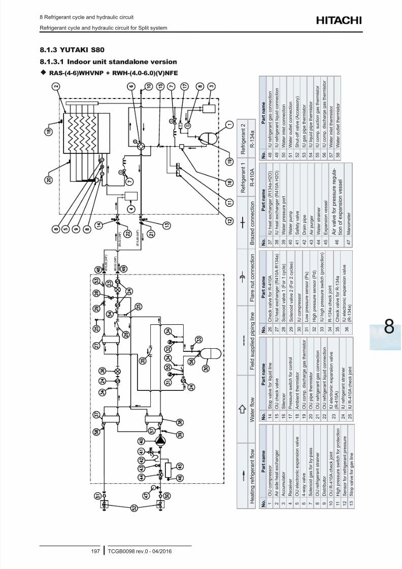
8/16/2019 Hitachi Yutaki Series 2016 Αντλίες θερμότητας
http://slidepdf.com/reader/full/hitachi-yutaki-series-2016- 207/256
8 Refrigerant cycle and hydraulic circuit
Refrigerant cycle and hydraulic circuit for Split system
TCGB0098 rev.0 - 04/2016197
8
8.1.3 YUTAKI S80
8.1.3.1 Indoor unit standalone version
RAS-(4-6)WHVNP + RWH-(4.0-6.0)(V)NFE
N o .
P a r t n a m e
1
O U c o m p r e s s o r
2
A i r s i d e h e a t e x c h a n g e r
3
A c c u m u l a t o r
4
R e c e i v e r
5
O U e l e c t r o n i c e x p a n s i o n v a l v e
6
4 - w a y v a l v e
7
S o l e n o i d g a s f o r b y - p a s s
8
O U r e f r i g e r a n t s t r a i n e r
9
D i s t r i b u t o r
1 0
O U R - 4 1 0 A c h e c k j o i n t
1 1
H i g h p r e s s u r e s w i t c h f o r p r o t e c t i o n
1 2
S e n s o r f o r r e f r i g e r a n t p r e s s u r e
1 3
S t o p v a l v e f o r g a s l i n e
N o .
P a r t n a m e
1 4
S t o p v
a l v e f o r l i q u i d l i n e
1 5
O U c h
e c k v a l v e
1 6
S i l e n c
e r
1 7
P r e s s u r e s w i t c h f o r c o n t r o l
1 8
A m b i e
n t t h e r m i s t o r
1 9
O U c o
m p . d i s c h a r g e g a s t h e r m i s t o r
2 0
O U p i p e t h e r m i s t o r
2 1
O U r e
f r i g e r a n t g a s c o n n e c t i o n
2 2
O U r e
f r i g e r a n t l i q u i d c o n n e c t i o n
2 3
I U e l e c t r o n i c e x p a n s i o n v a l v e
( R - 4 1 0 A )
2 4
I U r e f r i g e r a n t s t r a i n e r
2 5
I U R - 4
1 0 A c h e c k j o i n t
N o .
P a r t n a m e
2 6
C h e c k v a l v e
f o r R - 4 1 0 A
2 7
I U h e a t e x c h
a n g e r ( R 4 1 0 A - R 1 3 4 a )
2 8
S o l e n o i d v a l v e 1 ( F o r 1 c y c l e )
2 9
S o l e n o i d v a l v e 2 ( F o r 2 c y c l e s )
3 0
I U c o m p r e s s
o r
3 1
L o w p r e s s u r
e s e n s o r ( P s )
3 2
H i g h p r e s s u r e s e n s o r ( P d )
3 3
I U h i g h p r e s s u r e s w i t c h ( p r o t e c t i o n )
3 4
R - 1 3 4 a c h e c
k j o i n t
3 5
C h e c k v a l v e
f o r R - 1 3 4 a
3 6
I U e l e c t r o n i c
e x p a n s i o n v a l v e
( R - 1 3 4 a )
N o .
P a r t n
a m e
3 7
I U h e a t e x c h a n g e r
( R 1 3 4 a - H 2 O )
3 8
I U h e a t e x c h a n g e r
( R 4 1 0 A - H 2 O )
3 9
W a t e r p r e s s u r e p o r t
4 0
W a t e r p u m p
4 1
S a f e t y v a l v e
4 2
D r a i n p i p e
4 3
A i r p u r g e r
4 4
W a t e r s t r a i n e r
4 5
E x p a n s i o n v e s s e l
4 6
A i r v a l v e f o r p r e s s u r e r e g u l a -
t i o n o f e x p a n s i o n v e s s e l
4 7
M a n o m e t e r
N o .
P a r t n a m e
4 8
I U r e f r i g e r a n t g a s c o n n e c
t i o n
4 9
I U r e f r i g e r a n t l i q u i d c o n n e
c t i o n
5 0
W a t e r i n l e t c o n n e c t i o n
5 1
W a t e r o u t l e t c o n n e c t i o n
5 2
S h u t - o f f v a l v e ( A c c e s s o r y
)
5 3
I U g a s p i p e t h e r m i s t o r
5 4
I U l i q u i d p i p e t h e r m i s t o r
5 5
I U c o m p . s u c t i o n g a s t h e r m i s t o r
5 6
I U c o m p . d i s c h a r g e g a s t h e r m i s t o r
5 7
W a t e r i n l e t t h e r m i s t o r
5 8
W a t e r o u t l e t t h e r m i s t o r
R e f r i g e r a n t 1
R e f r i g e r a n t 2
H e
a t i n g r e f r i g e r a n t o w
W a t e r o w
F i e l d s u p p l i e d p i p i n g l i n e
F l a r e n u t c o n n e c t i o n
B r a z e d c o n n e c t i o n
R - 4 1 0 A
R - 1 3 4 a
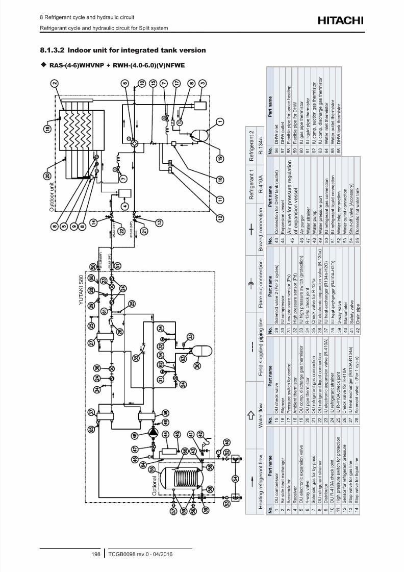
8/16/2019 Hitachi Yutaki Series 2016 Αντλίες θερμότητας
http://slidepdf.com/reader/full/hitachi-yutaki-series-2016- 208/256
8 Refrigerant cycle and hydraulic circuit
Refrigerant cycle and hydraulic circuit for Split system
TCGB0098 rev.0 - 04/2016198
8.1.3.2 Indoor unit for integrated tank version
RAS-(4-6)WHVNP + RWH-(4.0-6.0)(V)NFWE
R e f r i g e r a n t 1
R e f r i g e r a n t 2
H e a
t i n g r e f r i g e r a n t o w
W a t e r o w
F i e l d s u p p l i e d p i p i n g l i n e
F l a r
e n u t c o n n e c t i o n
B r a z e d c o n n e c t i o n
R - 4 1 0 A
R - 1 3 4 a
N o .
P a r t n a m e
1
O U c o m p r e s s o r
2
A i r s i d e h e a t e x c h a n g e r
3
A c c u m u l a t o r
4
R e c e i v e r
5
O U e l e c t r o n i c e x p a n s i o n v a l v e
6
4 - w a y v a l v e
7
S o l e n o i d g a s f o r b y - p a s s
8
O U r e f r i g e r a n t s t r a i n e r
9
D i s t r i b u t o r
1 0 O U R - 4 1 0 A c h e c k j o i n t
1 1 H i g h p r e s s u r e s w i t c h f o r p r o t e c t i o n
1 2 S e n s o r f o r r e f r i g e r a n t p r e s s u r e
1 3 S t o p v a l v e f o r g a s l i n e
1 4 S t o p v a l v e f o r l i q u i d l i n e
N o .
P a r t n a m e
1 5
O U c h e
c k v a l v e
1 6
S i l e n c e
r
1 7
P r e s s u r e s w i t c h f o r c o n t r o l
1 8
A m b i e n
t t h e r m i s t o r
1 9
O U c o m
p . d i s c h a r g e g a s t h e r m i s t o r
2 0
O U p i p e t h e r m i s t o r
2 1
O U r e f r
i g e r a n t g a s c o n n e c t i o n
2 2
O U r e f r
i g e r a n t l i q u i d c o n n e c t i o n
2 3
I U e l e c t r o n i c e x p a n s i o n v a l v e ( R - 4 1 0 A )
2 4
I U r e f r i g e r a n t s t r a i n e r
2 5
I U R - 4 1
0 A c h e c k j o i n t
2 6
C h e c k v a l v e f o r R - 4 1 0 A
2 7
I U h e a t e x c h a n g e r ( R 4 1 0 A - R 1 3 4 a )
2 8
S o l e n o i d v a l v e 1 ( F o r 1 c y c l e )
N o .
P a r t n a m e
2 9
S o l e n o i d v a l v e 2 ( F o r 2 c y c l e s )
3 0
I U c o m p r e s s o r
3 1
L o w p r e s s u r e s e n s o r ( P s )
3 2
H i g h p r e s s u r e s e n s o r ( P d )
3 3
I U h i g h p r e s s u r e s w i t c h ( p r o t e c t i o n )
3 4
R - 1 3 4 a c h e c
k j o i n t
3 5
C h e c k v a l v e
f o r R - 1 3 4 a
3 6
I U e l e c t r o n i c
e x p a n s i o n v a l v e ( R - 1 3 4 a )
3 7
I U h e a t e x c h
a n g e r ( R 1 3 4 a - H 2 O )
3 8
I U h e a t e x c h
a n g e r ( R 4 1 0 A - H 2 O )
3 9
3 - w a y v a l v e
4 0
M a n o m e t e r
4 1
S a f e t y v a l v e
4 2
D r a i n p i p e
N o .
P a r t n a m e
4 3
C o n n e c t i o n f o r D H
W
t a n k ( o u t l e t )
4 4
E x p a n s i o n v e s s e l
4 5
A i r v a l v e f o r p r e
s s u r e r e g u l a t i o n
o f e x p a n s i o n v e
s s e l
4 6
A i r p u r g e r
4 7
W a t e r s t r a i n e r
4 8
W a t e r p u m p
4 9
W a t e r p r e s s u r e p o
r t
5 0
I U r e f r i g e r a n t g a s c o n n e c t i o n
5 1
I U r e f r i g e r a n t l i q u i d c o n n e c t i o n
5 2
W a t e r i n l e t c o n n e c
t i o n
5 3
W a t e r o u t l e t c o n n e c t i o n
5 4
S h u t - o f f v a l v e ( A c c e s s o r y )
5 5
D o m e s t i c h o t w a t e
r t a n k
N o .
P a r t n a m
e
5 6
D H W i n l e t
5 7
D H W o u t l e t
5 8
F l e x i b l e p i p e f o r s p a c e h e a t i n g
5 9
F l e x i b l e p i p e f o r D H W
6 0
I U g a s p i p e t h e r m i s t o r
6 1
I U l i q u i d p i p e t h e r m i s t o r
6 2
I U c o m p . s u c t i o n g a s t h
e r m i s t o r
6 3
I U c o m p . d i s c h a r g e g a s
t h e r m i s t o r
6 4
W a t e r i n l e t t h e r m i s t o r
6 5
W a t e r o u t l e t t h e r m i s t o r
6 6
D H W t a n k t h e r m i s t o r
O u t d o
o r u n i t
Y U
T A K I S 8 0
O p t i o n a l
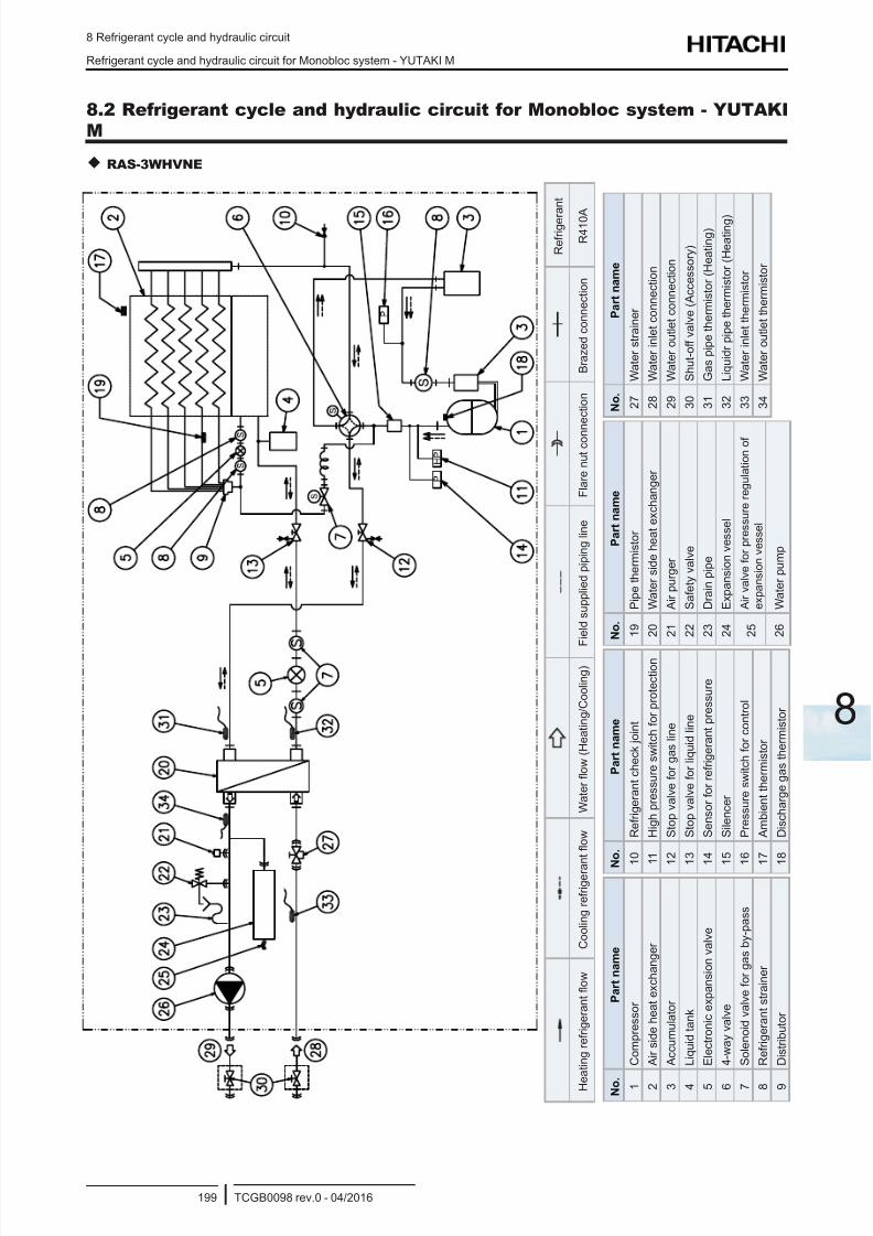
8/16/2019 Hitachi Yutaki Series 2016 Αντλίες θερμότητας
http://slidepdf.com/reader/full/hitachi-yutaki-series-2016- 209/256
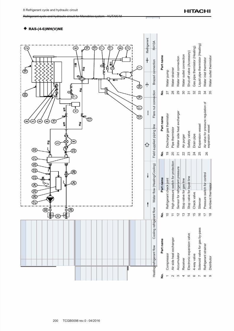
8/16/2019 Hitachi Yutaki Series 2016 Αντλίες θερμότητας
http://slidepdf.com/reader/full/hitachi-yutaki-series-2016- 210/256
8 Refrigerant cycle and hydraulic circuit
Refrigerant cycle and hydraulic circuit for Monobloc system - YUTAKI M
TCGB0098 rev.0 - 04/2016200
RAS-(4-6)WH(V)NE
R e f r i g e r a n t
H e a t i n g r e f r i g e r a n t o w
C o o l i n g r e f r i g e r a n t o w
W a t e r o w ( H e a t i n g / C
o o l i n g )
F i e l d s u p p l i e d p i p i n g l i n e
F l a r e n u t c o n n e c t i o n
B r a z e d c o n n e c t i o n
R 4 1 0 A
N o .
P a r t n a m e
1
C o m p r e s s o r
2
A i r s i d e h e a t e x c h a n g e r
3
A c c u m u l a t o r
4
R e c e i v e r
5
E l e c t r o n i c e x p a n s i o n v a l v e
6
4 - w a y v a l v e
7
S o l e n o i d v a l v e f o r g a s b y - p a
s s
8
R e f r i g e r a n t s t r a i n e r
9
D i s t r i b u t o r
N o .
P a r t n a m e
1 0
R e f r i g e r a n t c h e c k j o i n t
1 1
H i g h p r e s s u r e s w i t c h f o r p
r o t e c t i o n
1 2
S e n s o r f o r r e f r i g e r a n t p r e s
s u r e
1 3
S t o p v a l v e f o r g a s l i n e
1 4
S t o p v a l v e f o r l i q u i d l i n e
1 5
C h e c k v a l v e
1 6
S i l e n c e r
1 7
P r e s s u r e s w i t c h f o r c o n t r o
l
1 8
A m b i e n t t h e r m i s t o r
N o .
P a r t n a m e
1 9
D i s c h a r g e g a s t h e r m i s t o
r
2 0
P i p e t h e r m i s t o r
2 1
W a t e r s i d e h e a t e x c h a n g e r
2 2
A i r p u r g e r
2 3
S a f e t y v a l v e
2 4
D r a i n p i p e
2 5
E x p a n s i o n v e s s e l
2 6
A i r v a l v e f o r p r e s s u r e r e g u l a t i o n o f
e x p a n s i o n v e s s e l
N o .
P a r t n a m
e
2 7
W a t e r p u m p
2 8
W a t e r s t r a i n e r
2 9
W a t e r i n l e t c o n n e c t i o n
3 0
W a t e r o u t l e t c o n n e c t i o n
3 1
S h u t - o f f v a l v e ( A c c e s s o r y )
3 2
G a s p i p e t h e r m i s t o r ( H e a t i n g )
3 3
L i q u i d p i p e t h e r m i s t o r
( H e a t i n g )
3 4
W a t e r i n l e t t h e r m i s t o r
3 5
W a t e r o u t l e t t h e r m i s t o
r
8/16/2019 Hitachi Yutaki Series 2016 Αντλίες θερμότητας
http://slidepdf.com/reader/full/hitachi-yutaki-series-2016- 211/256
9 Refrigerant and water piping
TCGB0098 rev.0 - 04/2016201
9
Index
9.1 General notes before performing piping work ..................................................................................... 202
9.1.1 Piping work .................................................................................................................................................. 202
9.1.2 Suspension of refrigerant and water pipes ..................................................................................................202
9.2 Refrigerant circuit ................................................................................................................................203
9.2.1 Refrigerant piping ........................................................................................................................................ 203
9.2.2 Refrigerant charge ....................................................................................................................................... 204
9.2.2.1 Refrigerant charge amount ............................................................................................................ 204
9.2.2.2 Refrigerant charge before shipment (W0 (kg)) ............................................................................... 204
9.2.3 Precautions in the event of gas refrigerant leaks ........................................................................................ 205
9.3 Space heating and DHW .....................................................................................................................207
9.3.1 Additional hydraulic necessary elements for space heating ........................................................................ 207
9.3.2 Additional hydraulic necessary elements for DHW...................................................................................... 207
9.3.3 Additional hydraulic optional elements (For DHW) ...................................................................................... 210
9.3.5 Requirements and recommendations for the hydraulic circuit .................................................................... 210
9.3.6 Water piping ................................................................................................................................................ 212
9.3.7 Water quality (Preliminary information) .....................................................................................................215
9 . R e f r i g e r a n t a n d w a t e r p i p i n g
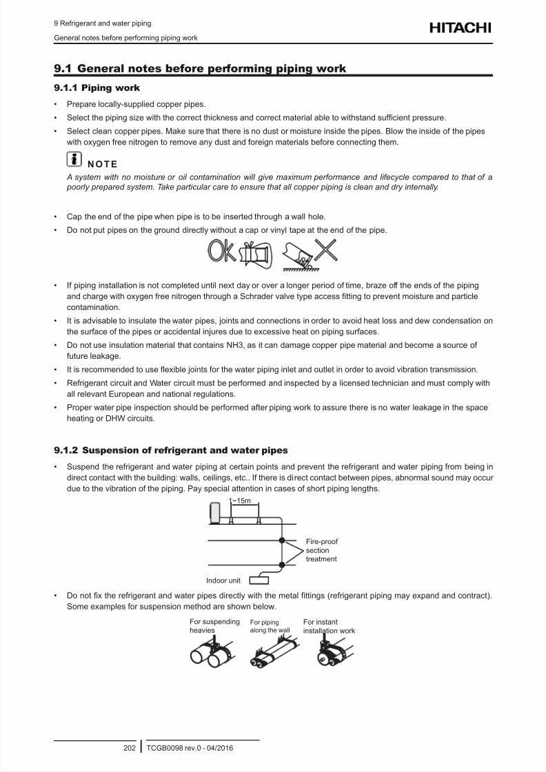
8/16/2019 Hitachi Yutaki Series 2016 Αντλίες θερμότητας
http://slidepdf.com/reader/full/hitachi-yutaki-series-2016- 212/256
9 Refrigerant and water piping
General notes before performing piping work
TCGB0098 rev.0 - 04/2016202
9.1 General notes before performing piping work
9.1.1 Piping work
• Prepare locally-supplied copper pipes.
• Select the piping size with the correct thickness and correct material able to withstand sufcient pressure.
• Select clean copper pipes. Make sure that there is no dust or moisture inside the pipes. Blow the inside of the pipeswith oxygen free nitrogen to remove any dust and foreign materials before connecting them.
N O T E
A system with no moisture or oil contamination will give maximum performance and lifecycle compared to that of a
poorly prepared system. Take particular care to ensure that all copper piping is clean and dry internally.
• Cap the end of the pipe when pipe is to be inserted through a wall hole.
• Do not put pipes on the ground directly without a cap or vinyl tape at the end of the pipe.
• If piping installation is not completed until next day or over a longer period of time, braze off the ends of the piping
and charge with oxygen free nitrogen through a Schrader valve type access tting to prevent moisture and particle
contamination.
• It is advisable to insulate the water pipes, joints and connections in order to avoid heat loss and dew condensation on
the surface of the pipes or accidental injures due to excessive heat on piping surfaces.
• Do not use insulation material that contains NH3, as it can damage copper pipe material and become a source of
future leakage.
• It is recommended to use exible joints for the water piping inlet and outlet in order to avoid vibration transmission.
• Refrigerant circuit and Water circuit must be performed and inspected by a licensed technician and must comply with
all relevant European and national regulations.
• Proper water pipe inspection should be performed after piping work to assure there is no water leakage in the spaceheating or DHW circuits.
9.1.2 Suspension of refrigerant and water pipes
• Suspend the refrigerant and water piping at certain points and prevent the refrigerant and water piping from being in
direct contact with the building: walls, ceilings, etc.. If there is direct contact between pipes, abnormal sound may occur
due to the vibration of the piping. Pay special attention in cases of short piping lengths.
Fire-proofsectiontreatment
1~15m
Indoor unit
• Do not x the refrigerant and water pipes directly with the metal ttings (refrigerant piping may expand and contract).
Some examples for suspension method are shown below.
For suspendingheavies
For pipingalong the wall
For instantinstallation work
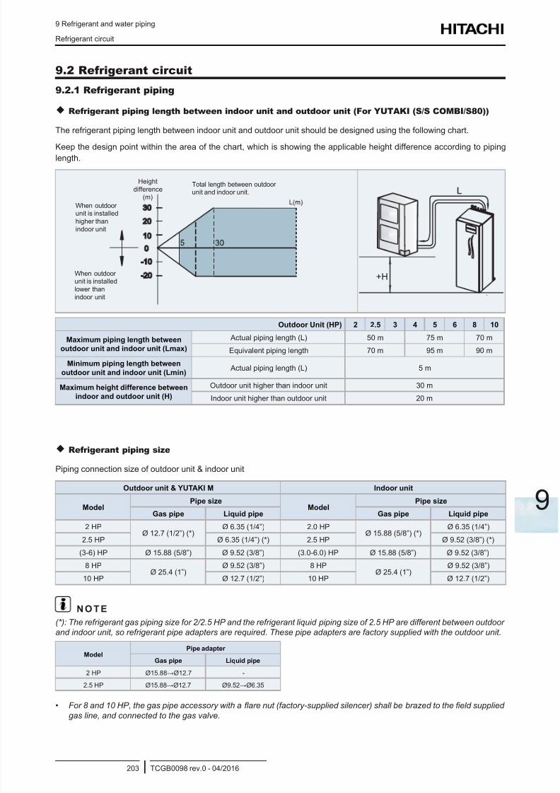
8/16/2019 Hitachi Yutaki Series 2016 Αντλίες θερμότητας
http://slidepdf.com/reader/full/hitachi-yutaki-series-2016- 213/256
9 Refrigerant and water piping
Refrigerant circuit
TCGB0098 rev.0 - 04/2016203
9
9.2 Refrigerant circuit
9.2.1 Refrigerant piping
Refrigerant piping length between indoor unit and outdoor unit (For YUTAKI (S/S COMBI/S80))
The refrigerant piping length between indoor unit and outdoor unit should be designed using the following chart.
Keep the design point within the area of the chart, which is showing the applicable height difference according to piping
length.
When outdoorunit is installedhigher thanindoor unit
When outdoorunit is installedlower thanindoor unit
Heightdifference
(m)
Total length between outdoorunit and indoor unit.
+H
Outdoor Unit (HP) 2 2.5 3 4 5 6 8 10
Maximum piping length between
outdoor unit and indoor unit (Lmax)
Actual piping length (L) 50 m 75 m 70 m
Equivalent piping length 70 m 95 m 90 m
Minimum piping length between
outdoor unit and indoor unit (Lmin) Actual piping length (L) 5 m
Maximum height difference between
indoor and outdoor unit (H)
Outdoor unit higher than indoor unit 30 m
Indoor unit higher than outdoor unit 20 m
Refrigerant piping size
Piping connection size of outdoor unit & indoor unit
Outdoor unit & YUTAKI M Indoor unit
ModelPipe size
ModelPipe size
Gas pipe Liquid pipe Gas pipe Liquid pipe
2 HPØ 12.7 (1/2”) (*)
Ø 6.35 (1/4”) 2.0 HPØ 15.88 (5/8”) (*)
Ø 6.35 (1/4”)
2.5 HP Ø 6.35 (1/4”) (*) 2.5 HP Ø 9.52 (3/8”) (*)
(3-6) HP Ø 15.88 (5/8”) Ø 9.52 (3/8”) (3.0-6.0) HP Ø 15.88 (5/8”) Ø 9.52 (3/8”)8 HP
Ø 25.4 (1”)Ø 9.52 (3/8”) 8 HP
Ø 25.4 (1”)Ø 9.52 (3/8”)
10 HP Ø 12.7 (1/2”) 10 HP Ø 12.7 (1/2”)
N O T E
(*): The refrigerant gas piping size for 2/2.5 HP and the refrigerant liquid piping size of 2.5 HP are different between outdoor
and indoor unit, so refrigerant pipe adapters are required. These pipe adapters are factory supplied with the outdoor unit.
ModelPipe adapter
Gas pipe Liquid pipe
2 HP Ø15.88→Ø12.7 -
2.5 HP Ø15.88→Ø12.7 Ø9.52→Ø6.35
• For 8 and 10 HP, the gas pipe accessory with a are nut (factory-supplied silencer) shall be brazed to the eld supplied
gas line, and connected to the gas valve.
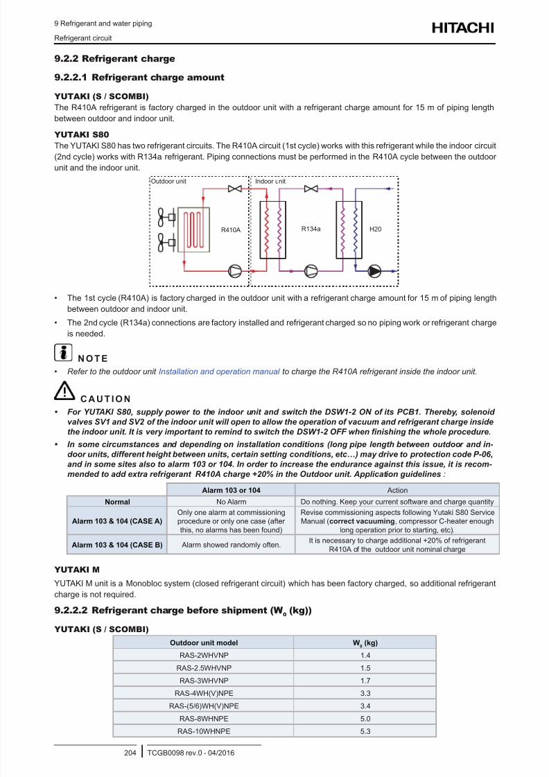
8/16/2019 Hitachi Yutaki Series 2016 Αντλίες θερμότητας
http://slidepdf.com/reader/full/hitachi-yutaki-series-2016- 214/256
9 Refrigerant and water piping
Refrigerant circuit
TCGB0098 rev.0 - 04/2016204
9.2.2 Refrigerant charge
9.2.2.1 Refrigerant charge amount
YUTAKI (S / SCOMBI)
The R410A refrigerant is factory charged in the outdoor unit with a refrigerant charge amount for 15 m of piping length
between outdoor and indoor unit.
YUTAKI S80The YUTAKI S80 has two refrigerant circuits. The R410A circuit (1st cycle) works with this refrigerant while the indoor circuit
(2nd cycle) works with R134a refrigerant. Piping connections must be performed in the R410A cycle between the outdoor
unit and the indoor unit.
Outdoor unit Indoor unit
R410A H20R134a
• The 1st cycle (R410A) is factory charged in the outdoor unit with a refrigerant charge amount for 15 m of piping length
between outdoor and indoor unit.
• The 2nd cycle (R134a) connections are factory installed and refrigerant charged so no piping work or refrigerant charge
is needed.
N O T E
• Refer to the outdoor unit Installation and operation manual to charge the R410A refrigerant inside the indoor unit.
C A U T I O N
• For YUTAKI S80, supply power to the indoor unit and switch the DSW1-2 ON of its PCB1. Thereby, solenoid
valves SV1 and SV2 of the indoor unit will open to allow the operation of vacuum and refrigerant charge inside
the indoor unit. It is very important to remind to switch the DSW1-2 OFF when nishing the whole procedure.
• In some circumstances and depending on installation conditions (long pipe length between outdoor and in-
door units, different height between units, certain setting conditions, etc…) may drive to protection code P-06,
and in some sites also to alarm 103 or 104. In order to increase the endurance against this issue, it is recom-
mended to add extra refrigerant R410A charge +20% in the Outdoor unit. Application guidelines:
Alarm 103 or 104 Action
Normal No Alarm Do nothing. Keep your current software and charge quantity
Alarm 103 & 104 (CASE A)
Only one alarm at commissioningprocedure or only one case (afterthis, no alarms has been found)
Revise commissioning aspects following Yutaki S80 ServiceManual (correct vacuuming, compressor C-heater enough
long operation prior to starting, etc).
Alarm 103 & 104 (CASE B) Alarm showed randomly often.It is necessary to charge additional +20% of refrigerant
R410A of the outdoor unit nominal charge
YUTAKI M
YUTAKI M unit is a Monobloc system (closed refrigerant circuit) which has been factory charged, so additional refrigerant
charge is not required.
9.2.2.2 Refrigerant charge before shipment (W0 (kg))
YUTAKI (S / SCOMBI)
Outdoor unit model W0 (kg)
RAS-2WHVNP 1.4
RAS-2.5WHVNP 1.5
RAS-3WHVNP 1.7RAS-4WH(V)NPE 3.3
RAS-(5/6)WH(V)NPE 3.4
RAS-8WHNPE 5.0
RAS-10WHNPE 5.3
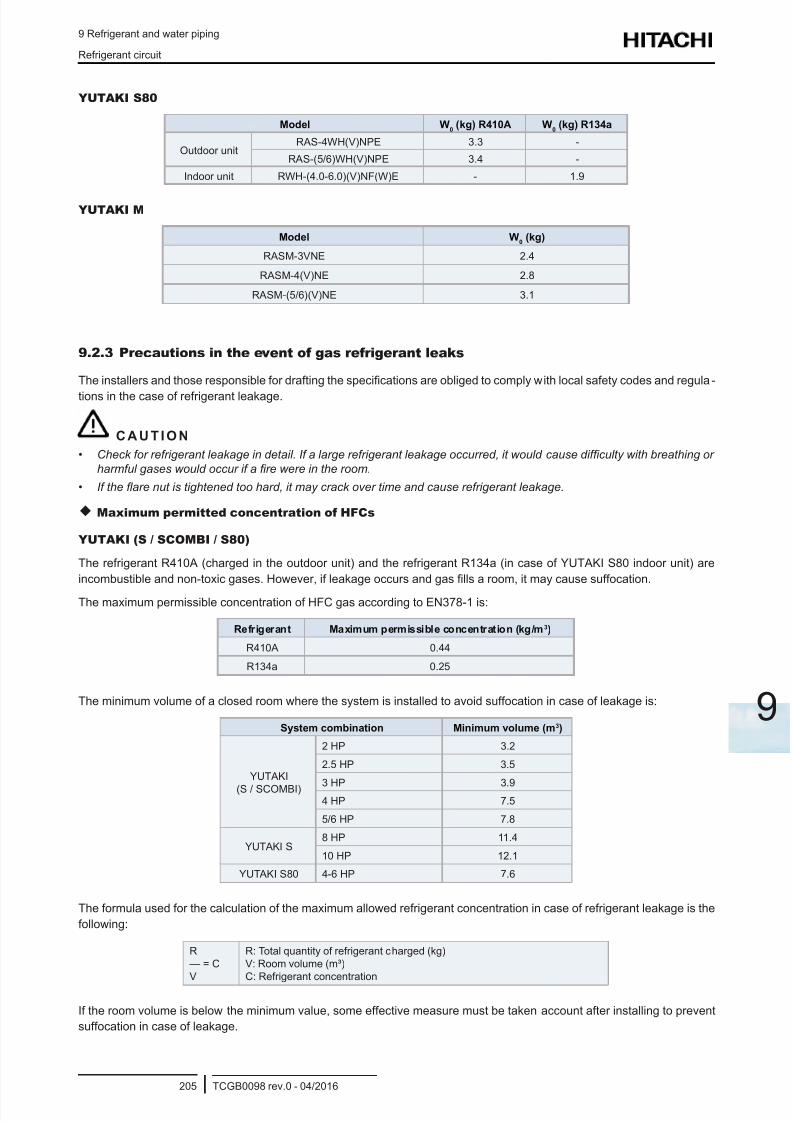
8/16/2019 Hitachi Yutaki Series 2016 Αντλίες θερμότητας
http://slidepdf.com/reader/full/hitachi-yutaki-series-2016- 215/256
9 Refrigerant and water piping
Refrigerant circuit
TCGB0098 rev.0 - 04/2016205
9
YUTAKI S80
Model W0 (kg) R410A W
0 (kg) R134a
Outdoor unitRAS-4WH(V)NPE 3.3 -
RAS-(5/6)WH(V)NPE 3.4 -
Indoor unit RWH-(4.0-6.0)(V)NF(W)E - 1.9
YUTAKI M
Model W0 (kg)
RASM-3VNE 2.4
RASM-4(V)NE 2.8
RASM-(5/6)(V)NE 3.1
9.2.3 Precautions in the event of gas refrigerant leaks
The installers and those responsible for drafting the specications are obliged to comply with local safety codes and regula-
tions in the case of refrigerant leakage.
C A U T I O N
• Check for refrigerant leakage in detail. If a large refrigerant leakage occurred, it would cause difculty with breathing or
harmful gases would occur if a re were in the room.
• If the are nut is tightened too hard, it may crack over time and cause refrigerant leakage.
Maximum permitted concentration of HFCs
YUTAKI (S / SCOMBI / S80)
The refrigerant R410A (charged in the outdoor unit) and the refrigerant R134a (in case of YUTAKI S80 indoor unit) are
incombustible and non-toxic gases. However, if leakage occurs and gas lls a room, it may cause suffocation.
The maximum permissible concentration of HFC gas according to EN378-1 is:
Refrigerant Maximum permissible concentration (kg/m3)
R410A 0.44
R134a 0.25
The minimum volume of a closed room where the system is installed to avoid suffocation in case of leakage is:
System combination Minimum volume (m3)
YUTAKI
(S / SCOMBI)
2 HP 3.2
2.5 HP 3.5
3 HP 3.94 HP 7.5
5/6 HP 7.8
YUTAKI S8 HP 11.4
10 HP 12.1
YUTAKI S80 4-6 HP 7.6
The formula used for the calculation of the maximum allowed refrigerant concentration in case of refrigerant leakage is the
following:
R— = CV
R: Total quantity of refrigerant charged (kg)V: Room volume (m³)C: Refrigerant concentration
If the room volume is below the minimum value, some effective measure must be taken account after installing to prevent
suffocation in case of leakage.
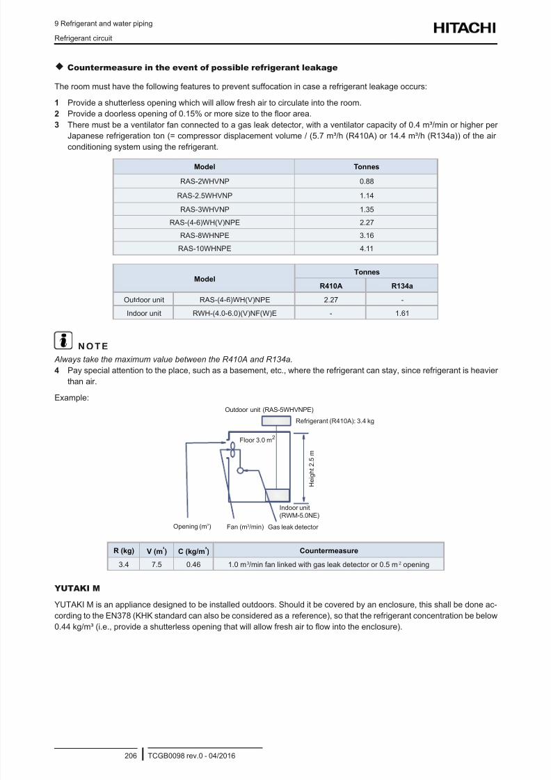
8/16/2019 Hitachi Yutaki Series 2016 Αντλίες θερμότητας
http://slidepdf.com/reader/full/hitachi-yutaki-series-2016- 216/256
9 Refrigerant and water piping
Refrigerant circuit
TCGB0098 rev.0 - 04/2016206
Countermeasure in the event of possible refrigerant leakage
The room must have the following features to prevent suffocation in case a refrigerant leakage occurs:
1 Provide a shutterless opening which will allow fresh air to circulate into the room.
2 Provide a doorless opening of 0.15% or more size to the oor area.
3 There must be a ventilator fan connected to a gas leak detector, with a ventilator capacity of 0.4 m³/min or higher per
Japanese refrigeration ton (= compressor displacement volume / (5.7 m³/h (R410A) or 14.4 m³/h (R134a)) of the airconditioning system using the refrigerant.
Model Tonnes
RAS-2WHVNP 0.88
RAS-2.5WHVNP 1.14
RAS-3WHVNP 1.35
RAS-(4-6)WH(V)NPE 2.27
RAS-8WHNPE 3.16
RAS-10WHNPE 4.11
Model Tonnes
R410A R134a
Outdoor unit RAS-(4-6)WH(V)NPE 2.27 -
Indoor unit RWH-(4.0-6.0)(V)NF(W)E - 1.61
N O T E
Always take the maximum value between the R410A and R134a.
4 Pay special attention to the place, such as a basement, etc., where the refrigerant can stay, since refrigerant is heavier
than air.
Example:
Outdoor unit (RAS-5WHVNPE)Refrigerant (R410A): 3.4 kg
Gas leak detectorFan (m3/min)
H e i g h t 2 . 5 m
Floor 3.0 m2
Opening (m2)
Indoor unit(RWM-5.0NE)
R (kg) V (m³) C (kg/m³) Countermeasure
3.4 7.5 0.46 1.0 m3/min fan linked with gas leak detector or 0.5 m2 opening
YUTAKI M
YUTAKI M is an appliance designed to be installed outdoors. Should it be covered by an enclosure, this shall be done ac-
cording to the EN378 (KHK standard can also be considered as a reference), so that the refrigerant concentration be below
0.44 kg/m³ (i.e., provide a shutterless opening that will allow fresh air to ow into the enclosure).
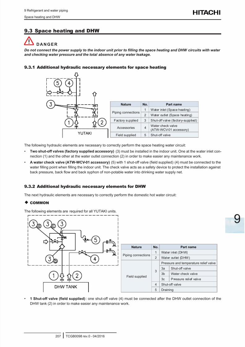
8/16/2019 Hitachi Yutaki Series 2016 Αντλίες θερμότητας
http://slidepdf.com/reader/full/hitachi-yutaki-series-2016- 217/256
9 Refrigerant and water piping
Space heating and DHW
TCGB0098 rev.0 - 04/2016207
9
9.3 Space heating and DHW
D A N G E R
Do not connect the power supply to the indoor unit prior to lling the space heating and DHW circuits with water
and checking water pressure and the total absence of any water leakage.
9.3.1 Additional hydraulic necessary elements for space heating
Nature No. Part name
Piping connections1 Water inlet (Space heating)
2 Water outlet (Space heating)
Factory supplied 3 Shut-off valve (factory-supplied)
Accessories 4Water check valve(ATW-WCV-01 accessory)
Field supplied 5 Shut-off valve
The following hydraulic elements are necessary to correctly perform the space heating water circuit:
• Two shut-off valves (factory supplied accessory) (3) must be installed in the indoor unit. One at the water inlet con-
nection (1) and the other at the water outlet connection (2) in order to make easier any maintenance work.
• A water check valve (ATW-WCV-01 accessory) (5) with 1 shut-off valve (eld supplied) (4) must be connected to the
water lling point when lling the indoor unit. The check valve acts as a safety device to protect the installation against
back pressure, back ow and back syphon of non-potable water into drinking water supply net.
9.3.2 Additional hydraulic necessary elements for DHW
The next hydraulic elements are necessary to correctly perform the domestic hot water circuit:
COMMON
The following elements are required for all YUTAKI units.
Nature No. Part name
Piping connections1 Water inlet (DHW)
2 Water outlet (DHW)
Field supplied
3
Pressure and temperature relief valve
3a Shut-off valve
3b Water check valve
3c Pressure relief valve
4 Shut-off valve
5 Draining
• 1 Shut-off valve (eld supplied): one shut-off valve (4) must be connected after the DHW outlet connection of the
DHW tank (2) in order to make easier any maintenance work.
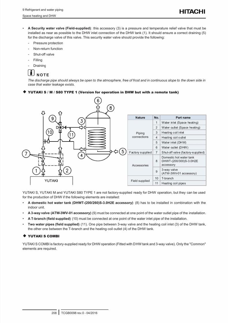
8/16/2019 Hitachi Yutaki Series 2016 Αντλίες θερμότητας
http://slidepdf.com/reader/full/hitachi-yutaki-series-2016- 218/256
9 Refrigerant and water piping
Space heating and DHW
TCGB0098 rev.0 - 04/2016208
• A Security water valve (Field-supplied): this accessory (3) is a pressure and temperature relief valve that must be
installed as near as possible to the DHW inlet connection of the DHW tank (1). It should ensure a correct draining (5)
for the discharge valve of this valve. This security water valve should provide the following:
- Pressure protection
- Non-return function
- Shut-off valve
- Filling
- Draining
N O T E
The discharge pipe should always be open to the atmosphere, free of frost and in continuous slope to the down side in
case that water leakage exists.
YUTAKI S / M / S80 TYPE 1 (Version for operation in DHW but with a remote tank)
Nature No. Part name
Pipingconnections
1 Water inlet (Space heating)
2 Water outlet (Space heating)
3 Heating coil inlet
4 Heating coil outlet
5 Water inlet (DHW)
6 Water outlet (DHW)
Factory supplied 7 Shut-off valve (factory-supplied)
Accessories
8Domestic hot water tankDHWT-(200/300)S-3.0H2Eaccessory
9 3-way valve(ATW-3WV-01 accessory)
Field supplied10 T-branch
11 Heating coil pipes
YUTAKI S, YUTAKI M and YUTAKI S80 TYPE 1 are not factory-supplied ready for DHW operation, but they can be used
for the production of DHW if the following elements are installed:
• A domestic hot water tank (DHWT-(200/260)S-3.0H2E accessory) (8) has to be installed in combination with the
indoor unit.
• A 3-way valve (ATW-3WV-01 accessory) (9) must be connected at one point of the water outlet pipe of the installation.
• A T-branch (eld supplied) (10) must be connected at one point of the water inlet pipe of the installation.
• Two water pipes (eld supplied) (11). One pipe between 3-way valve and the heating coil inlet (3) of the DHW tank,
the other one between the T-branch and the heating coil outlet (4) of the DHW tank.
YUTAKI S COMBI
YUTAKI S COMBI is factory-supplied ready for DHW operation (Fitted with DHW tank and 3-way valve). Only the "Common"
elements are required.
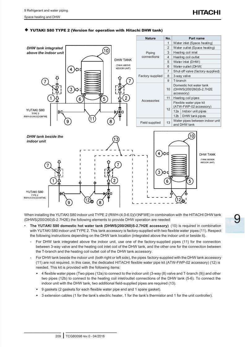
8/16/2019 Hitachi Yutaki Series 2016 Αντλίες θερμότητας
http://slidepdf.com/reader/full/hitachi-yutaki-series-2016- 219/256
9 Refrigerant and water piping
Space heating and DHW
TCGB0098 rev.0 - 04/2016209
9
YUTAKI S80 TYPE 2 (Version for operation with Hitachi DHW tank)
Nature No. Part name
Pipingconnections
1 Water inlet (Space heating)
2 Water outlet (Space heating)
3 Heating coil inlet
4 Heating coil outlet
5 Water inlet (DHW)6 Water outlet (DHW)
Factory supplied
7 Shut-off valve (factory-supplied)
8 3-way valve
9 T-branch
Accessories
10Domestic hot water tank(DHWS(200/260)S-2.7H2Eaccessory)
11 Heating coil pipes
12
Flexible water pipe kit(ATW-FWP-02 accessory)
12a Indoor unit pipes
12b DHW tank pipes
Field supplied 13 Water pipes between indoor unitand DHW tank
DHW tank integrated
above the indoor unit
DHW tank beside the
indoor unit
When installing the YUTAKI S80 indoor unit TYPE 2 (RWH-(4.0-6.0)(V)NFWE) in combination with the HITACHI DHW tank
(DHWS(200/260)S-2.7H2E) the following elements to provide DHW operation are needed:
• The YUTAKI S80 domestic hot water tank (DHWS(200/260)S-2.7H2E accessory) (10) is required in combination
with YUTAKI S80 indoor unit TYPE 2. This tank accessory is factory-supplied with two exible water pipes (11). Respect
the following instructions depending on the DHW tank location (integrated above the indoor unit or beside it).
- For DHW tank integrated above the indoor unit, use one of the factory-supplied pipes (11) for the connectionbetween 3-way valve and the heating coil inlet coil of the DHW tank, and the other one for the connection between
the T-branch and the heating coil outlet coil of the DHW tank accessory.
- For DHW tank beside the indoor unit (both right or left side), the pipes factory-supplied with the DHW tank accessory
(11) are not required. In this case, the dedicated HITACHI exible water pipe kit (ATW-FWP-02 accessory) (12) is
needed. This kit is provided with the following items:
4 exible water pipes (Two pipes (12a) to connect to the indoor unit (3-way (8) valve and T-branch (9)) and other
two pipes (12b) to connect to the heating coil inlet/outlet connections of the DHW tank (5-6). To connect the
indoor unit with the DHW tank, two additional eld-supplied pipes are required (13).
9 gaskets (2 gaskets for each exible water pipe end and 1 spare gasket).
3 extension cables (1 for the tank’s electric heater, 1 for the tank’s thermistor and 1 for the unit controller).
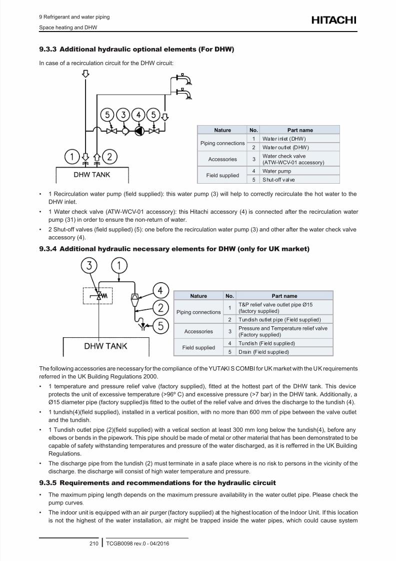
8/16/2019 Hitachi Yutaki Series 2016 Αντλίες θερμότητας
http://slidepdf.com/reader/full/hitachi-yutaki-series-2016- 220/256
9 Refrigerant and water piping
Space heating and DHW
TCGB0098 rev.0 - 04/2016210
9.3.3 Additional hydraulic optional elements (For DHW)
In case of a recirculation circuit for the DHW circuit:
Nature No. Part name
Piping connections1 Water inlet (DHW)
2 Water outlet (DHW)
Accessories 3Water check valve(ATW-WCV-01 accessory)
Field supplied4 Water pump
5 Shut-off valve
• 1 Recirculation water pump (eld supplied): this water pump (3) will help to correctly recirculate the hot water to theDHW inlet.
• 1 Water check valve (ATW-WCV-01 accessory): this Hitachi accessory (4) is connected after the recirculation water
pump (31) in order to ensure the non-return of water.
• 2 Shut-off valves (eld supplied) (5): one before the recirculation water pump (3) and other after the water check valve
accessory (4).
9.3.4 Additional hydraulic necessary elements for DHW (only for UK market)
Nature No. Part name
Piping connections1
T&P relief valve outlet pipe Ø15(factory supplied)
2 Tundish outlet pipe (Field supplied)
Accessories 3Pressure and Temperature relief valve(Factory supplied)
Field supplied4 Tundish (Field supplied)
5 Drain (Field supplied)
The following accessories are necessary for the compliance of the YUTAKI S COMBI for UK market with the UK requirements
referred in the UK Building Regulations 2000.
• 1 temperature and pressure relief valve (factory supplied), tted at the hottest part of the DHW tank. This device
protects the unit of excessive temperature (>96º C) and excessive pressure (>7 bar) in the DHW tank. Additionally, aØ15 diameter pipe (factory supplied)is tted to the outlet of the relief valve and drives the discharge to the tundish (4).
• 1 tundish(4)(eld supplied), installed in a vertical position, with no more than 600 mm of pipe between the valve outlet
and the tundish.
• 1 Tundish outlet pipe (2)(eld supplied) with a vetical section at least 300 mm long below the tundish(4), before any
elbows or bends in the pipework. This pipe should be made of metal or other material that has been demonstrated to be
capable of safety withstanding temperatures and pressure of the water discharged, as it is refferred in the UK Building
Regulations.
• The discharge pipe from the tundish (2) must terminate in a safe place where is no risk to persons in the vicinity of the
discharge. the discharge will consist of high water temperature and pressure.
9.3.5 Requirements and recommendations for the hydraulic circuit
• The maximum piping length depends on the maximum pressure availability in the water outlet pipe. Please check the
pump curves.
• The indoor unit is equipped with an air purger (factory supplied) at the highest location of the Indoor Unit. If this location
is not the highest of the water installation, air might be trapped inside the water pipes, which could cause system
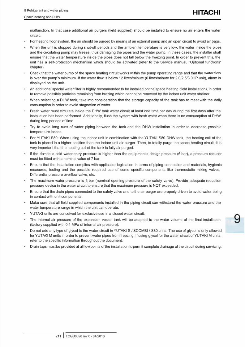
8/16/2019 Hitachi Yutaki Series 2016 Αντλίες θερμότητας
http://slidepdf.com/reader/full/hitachi-yutaki-series-2016- 221/256
9 Refrigerant and water piping
Space heating and DHW
TCGB0098 rev.0 - 04/2016211
9
malfunction. In that case additional air purgers (eld supplied) should be installed to ensure no air enters the water
circuit.
• For heating oor system, the air should be purged by means of an external pump and an open circuit to avoid air bags.
• When the unit is stopped during shut-off periods and the ambient temperature is very low, the water inside the pipes
and the circulating pump may freeze, thus damaging the pipes and the water pump. In these cases, the installer shall
ensure that the water temperature inside the pipes does not fall below the freezing point. In order to prevent this, the
unit has a self-protection mechanism which should be activated (refer to the Service manual, "Optional functions"chapter).
• Check that the water pump of the space heating circuit works within the pump operating range and that the water ow
is over the pump’s minimum. If the water ow is below 12 litres/minute (6 litres/minute for 2.0/2.5/3.0HP unit), alarm is
displayed on the unit.
• An additional special water lter is highly recommended to be installed on the space heating (eld installation), in order
to remove possible particles remaining from brazing which cannot be removed by the indoor unit water strainer.
• When selecting a DHW tank, take into consideration that the storage capacity of the tank has to meet with the daily
consumption in order to avoid stagnation of water.
• Fresh water must circulate inside the DHW tank water circuit at least one time per day during the rst days after the
installation has been performed. Additionally, ush the system with fresh water when there is no consumption of DHW
during long periods of time.• Try to avoid long runs of water piping between the tank and the DHW installation in order to decrease possible
temperature losses.
• For YUTAKI S80: When using the indoor unit in combination with the YUTAKI S80 DHW tank, the heating coil of the
tank is placed in a higher position than the indoor unit air purger. Then, to totally purge the space heating circuit, it is
very important that the heating coil of the tank is fully air purged.
• lf the domestic cold water entry pressure is higher than the equipment’s design pressure (6 bar), a pressure reducer
must be tted with a nominal value of 7 bar.
• Ensure that the installation complies with applicable legislation in terms of piping connection and materials, hygienic
measures, testing and the possible required use of some specic components like thermostatic mixing valves,
Differential pressure overow valve, etc.
• The maximum water pressure is 3 bar (nominal opening pressure of the safety valve). Provide adequate reductionpressure device in the water circuit to ensure that the maximum pressure is NOT exceeded.
• Ensure that the drain pipes connected to the safety valve and to the air purger are properly driven to avoid water being
in contact with unit components.
• Make sure that all eld supplied components installed in the piping circuit can withstand the water pressure and the
water temperature range in which the unit can operate.
• YUTAKI units are conceived for exclusive use in a closed water circuit.
• The internal air pressure of the expansion vessel tank will be adapted to the water volume of the nal installation
(factory supplied with 0.1 MPa of internal air pressure).
• Do not add any type of glycol to the water circuit in YUTAKI S / SCOMBI / S80 units. The use of glycol is only allowed
for YUTAKI M units in order to prevent water pipes from freezing. If using glycol for the water circuit of YUTAKI M units,
refer to the specic information throughout the document.
• Drain taps must be provided at all low points of the installation to permit complete drainage of the circuit during servicing.
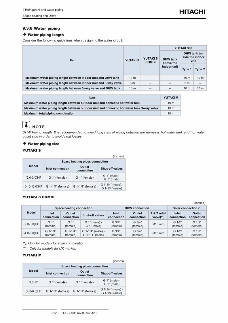
8/16/2019 Hitachi Yutaki Series 2016 Αντλίες θερμότητας
http://slidepdf.com/reader/full/hitachi-yutaki-series-2016- 222/256
9 Refrigerant and water piping
Space heating and DHW
TCGB0098 rev.0 - 04/2016212
9.3.6 Water piping
Water piping length
Consider the following guidelines when designing the water circuit.
Item YUTAKI S YUTAKI S
COMBI
YUTAKI S80
DHW tank
above the
indoor unit
DHW tank be-
side the indoorunit
Type 1 Type 2
Maximum water piping length between indoor unit and DHW tank 10 m -- -- 10 m 10 m
Maximum water piping length between indoor unit and 3-way valve 3 m -- -- 3 m --
Maximum water piping length between 3-way valve and DHW tank 10 m -- -- 10 m 10 m
Item YUTAKI M
Maximum water piping length between outdoor unit and domestic hot water tank 10 m
Maximum water piping length between outdoor unit and domestic hot water tank 3-way valve 10 m
Maximum total piping combination 10 m
N O T E
DHW Piping length. It is recommended to avoid long runs of piping between the domestic hot water tank and hot water
outlet side in order to avoid heat losses
Water piping size
YUTAKI S
(inches)
Model
Space heating pipes connection
Inlet connection
Outlet
connection Shut-off valves
(2.0-3.0)HP G 1” (female) G 1” (female)G 1” (male) -G 1” (male)
(4.0-10.0)HP G 1-1/4” (female) G 1-1/4” (female)G 1-1/4” (male) -G 1-1/4” (male)
YUTAKI S COMBI
(inches)
Model
Space heating connection DHW connection Solar connection (*)
Inlet
connection
Outlet
connectionShut-off valves
Inlet
connection
Outlet
connection
P & T relief
valve(**)
Inlet
connection
Outlet
connection
(2.0-3.0)HPG 1”
(female)
G 1”
(female)
G 1” (male) -
G 1” (male)
G 3/4”
(female)
G 3/4”
(female)Ø15 mm
G 1/2”
(female)
G 1/2”
(female)
(4.0-6.0)HPG 1-1/4”(female)
G 1-1/4”(female)
G 1-1/4” (male) -G 1-1/4” (male)
G 3/4”(female)
G 3/4”(female)
Ø15 mmG 1/2”
(female)G 1/2”
(female)
(*): Only for models for solar combination.
(**): Only for models for UK market.
YUTAKI M
(inches)
Model
Space heating pipes connection
Inlet connectionOutlet
connectionShut-off valves
3.0HP G 1” (female) G 1” (female)
G 1” (male) -
G 1” (male)
(4.0-6.0)HP G 1-1/4” (female) G 1-1/4” (female)G 1-1/4” (male) -G 1-1/4” (male)
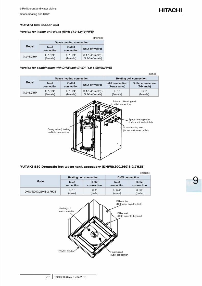
8/16/2019 Hitachi Yutaki Series 2016 Αντλίες θερμότητας
http://slidepdf.com/reader/full/hitachi-yutaki-series-2016- 223/256
9 Refrigerant and water piping
Space heating and DHW
TCGB0098 rev.0 - 04/2016213
9
YUTAKI S80 indoor unit
Version for indoor unit alone (RWH-(4.0-6.0)(V)NFE)
(inches)
Model
Space heating connection
Inlet
connection
Outlet
connection Shut-off valves
(4.0-6.0)HPG 1-1/4”(female)
G 1-1/4”(female)
G 1-1/4” (male) -G 1-1/4” (male)
Version for combination with DHW tank (RWH-(4.0-6.0)(V)NFWE)
(inches)
Model
Space heating connection Heating coil connection
Inlet
connection
Outlet
connectionShut-off valves
Inlet connection
(3-way valve)
Outlet connection
(T-branch)
(4.0-6.0)HPG 1-1/4”(female)
G 1-1/4”(female)
G 1-1/4” (male) -G 1-1/4” (male)
G 1”(female)
G 1”(female)
T-branch (Heating coiloutlet connection)
3-way valve (Heatingcoil inlet connection)
Space heating inlet(indoor unit water outlet)
Space heating outlet(indoor unit water inlet)
YUTAKI S80 Domestic hot water tank accessory (DHWS(200/260)S-2.7H2E)
(inches)
Model
Heating coil connection DHW connection
Inlet
connection
Outlet
connection
Inlet
connection
Outlet
connection
DHWS(200/260)S-2.7H2EG 1”
(male)G 1”
(male)G 3/4”(male)
G 3/4”(male)
DHW outlet(Hot water from the tank)
DHW inlet(Cold water to the tank)
Heating coilinlet connection
Heating coiloutlet connection
FRONT SIDE
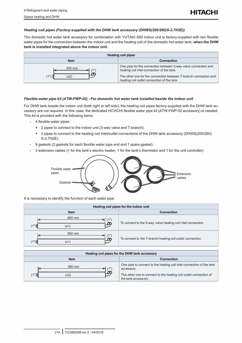
8/16/2019 Hitachi Yutaki Series 2016 Αντλίες θερμότητας
http://slidepdf.com/reader/full/hitachi-yutaki-series-2016- 224/256
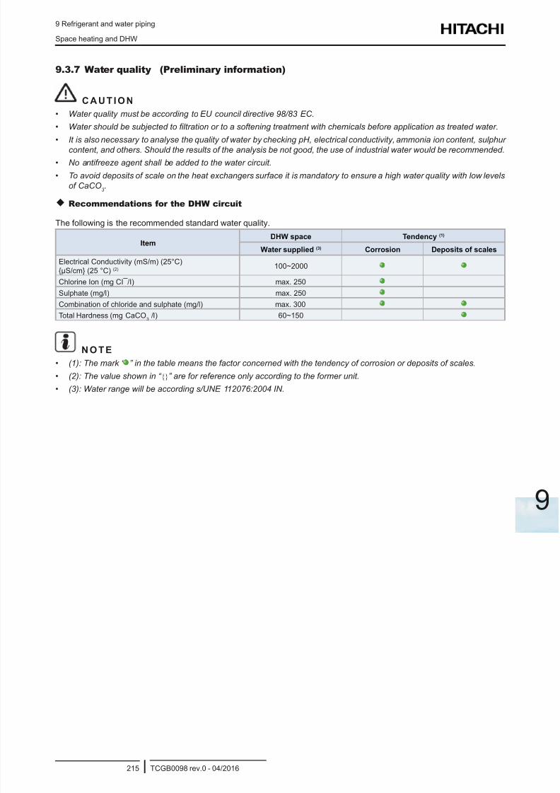
8/16/2019 Hitachi Yutaki Series 2016 Αντλίες θερμότητας
http://slidepdf.com/reader/full/hitachi-yutaki-series-2016- 225/256

8/16/2019 Hitachi Yutaki Series 2016 Αντλίες θερμότητας
http://slidepdf.com/reader/full/hitachi-yutaki-series-2016- 226/256
8/16/2019 Hitachi Yutaki Series 2016 Αντλίες θερμότητας
http://slidepdf.com/reader/full/hitachi-yutaki-series-2016- 227/256
10 Electrical and control settings
TCGB0098 rev.0 - 04/2016217
10
1 0 . E l e c t r i c a l a n d c o n t r o l s e t t i n g s
Index
10.1 General check ..................................................................................................................................... 218
10.2 System wiring diagram ........................................................................................................................ 221
10.3 Electrical connection ........................................................................................................................... 222
10.3.1 Wiring size ................................................................................................................................................. 222
10.3.2 Minimum requirements of the protection devices ......................................................................................225
10.4 Transmission wiring between outdoor and indoor unit ........................................................................ 227
10.5 Optional indoor unit wiring (accessories) ............................................................................................ 228
10.6 Setting of DIP switches and RSW switches ........................................................................................ 230
10.6.1 Outdoor unit ............................................................................................................................................... 230
10.6.1.1 Location of DIP switches and rotary switches .............................................................................. 230
10.6.1.2 Function of DIP switches and rotary switches .............................................................................. 231
10.6.1.3 LED indication .............................................................................................................................. 232
10.6.2 YUTAKI unit ............................................................................................................................................... 233
10.6.2.1 Location of DIP switches and rotary switches .............................................................................. 233
10.6.2.2 Function of DIP switches and rotary switches .............................................................................. 23310.6.2.3 LED indication .............................................................................................................................. 236
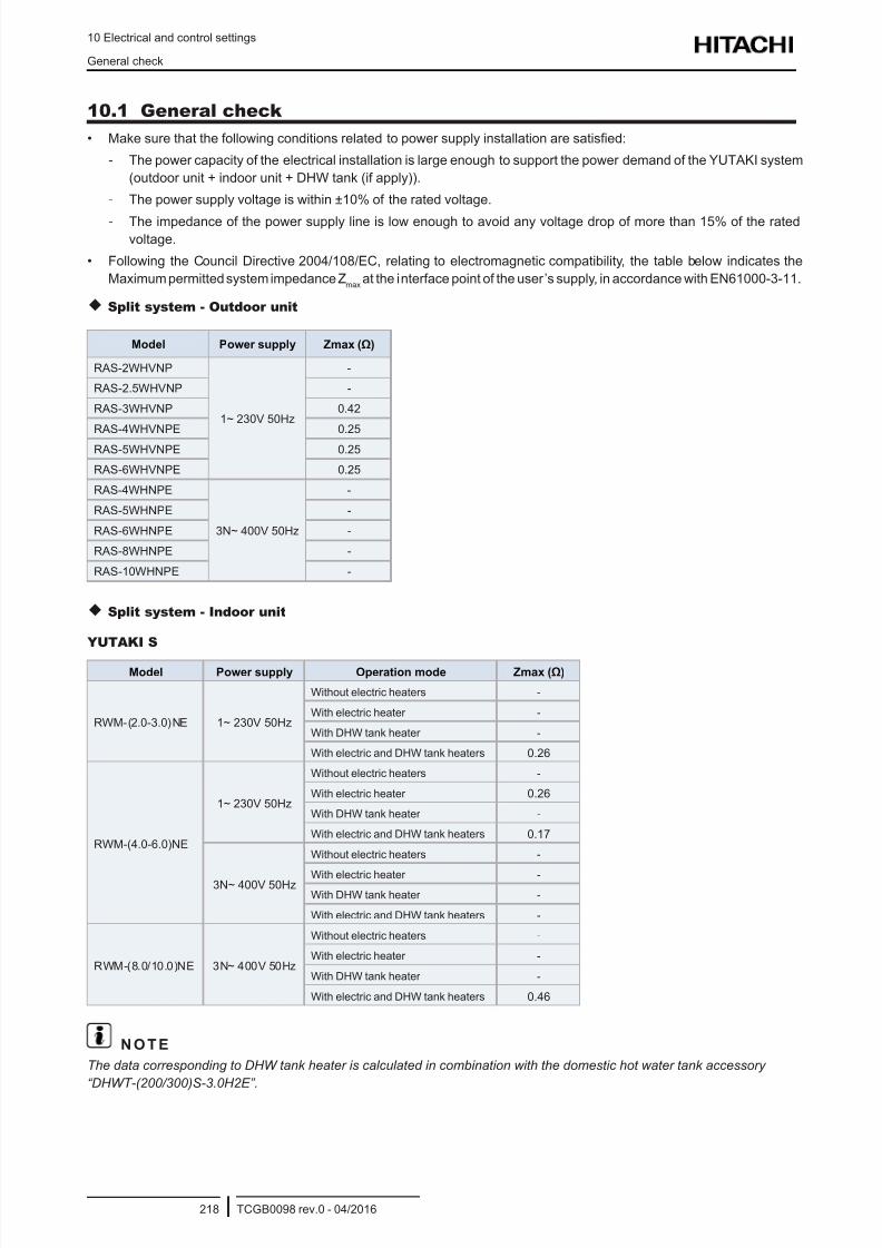
8/16/2019 Hitachi Yutaki Series 2016 Αντλίες θερμότητας
http://slidepdf.com/reader/full/hitachi-yutaki-series-2016- 228/256
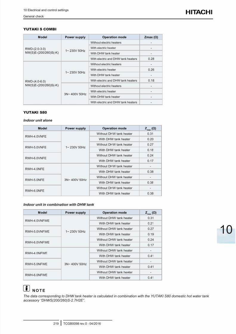
8/16/2019 Hitachi Yutaki Series 2016 Αντλίες θερμότητας
http://slidepdf.com/reader/full/hitachi-yutaki-series-2016- 229/256
10 Electrical and control settings
General check
TCGB0098 rev.0 - 04/2016219
10
YUTAKI S COMBI
Model Power supply Operation mode Zmax (Ω)
RWD-(2.0-3.0)
NW(S)E-(200/260)S(-K)1~ 230V 50Hz
Without electric heaters -
With electric heater -
With DHW tank heater -
With electric and DHW tank heaters 0.28
RWD-(4.0-6.0)
NW(S)E-(200/260)S(-K)
1~ 230V 50Hz
Without electric heaters -
With electric heater 0.26
With DHW tank heater -
With electric and DHW tank heaters 0.18
3N~ 400V 50Hz
Without electric heaters -
With electric heater -
With DHW tank heater -
With electric and DHW tank heaters -
YUTAKI S80
Indoor unit alone
Model Power supply Operation mode Zmax
(Ω)
RWH-4.0VNFE
1~ 230V 50Hz
Without DHW tank heater 0.31
With DHW tank heater 0.20
RWH-5.0VNFEWithout DHW tank heater 0.27
With DHW tank heater 0.18
RWH-6.0VNFEWithout DHW tank heater 0.24
With DHW tank heater 0.17
RWH-4.0NFE
3N~ 400V 50Hz
Without DHW tank heater -
With DHW tank heater 0.38
RWH-5.0NFEWithout DHW tank heater -
With DHW tank heater 0.38
RWH-6.0NFEWithout DHW tank heater -
With DHW tank heater 0.38
Indoor unit in combination with DHW tank
Model Power supply Operation mode Zmax
(Ω)
RWH-4.0VNFWE
1~ 230V 50Hz
Without DHW tank heater 0.31
With DHW tank heater 0.21
RWH-5.0VNFWEWithout DHW tank heater 0.27
With DHW tank heater 0.19
RWH-6.0VNFWEWithout DHW tank heater 0.24
With DHW tank heater 0.17
RWH-4.0NFWE
3N~ 400V 50Hz
Without DHW tank heater -
With DHW tank heater 0.41
RWH-5.0NFWEWithout DHW tank heater -
With DHW tank heater 0.41
RWH-6.0NFWEWithout DHW tank heater -
With DHW tank heater 0.41
N O T EThe data corresponding to DHW tank heater is calculated in combination with the YUTAKI S80 domestic hot water tank
accessory “DHWS(200/260)S-2.7H2E”.
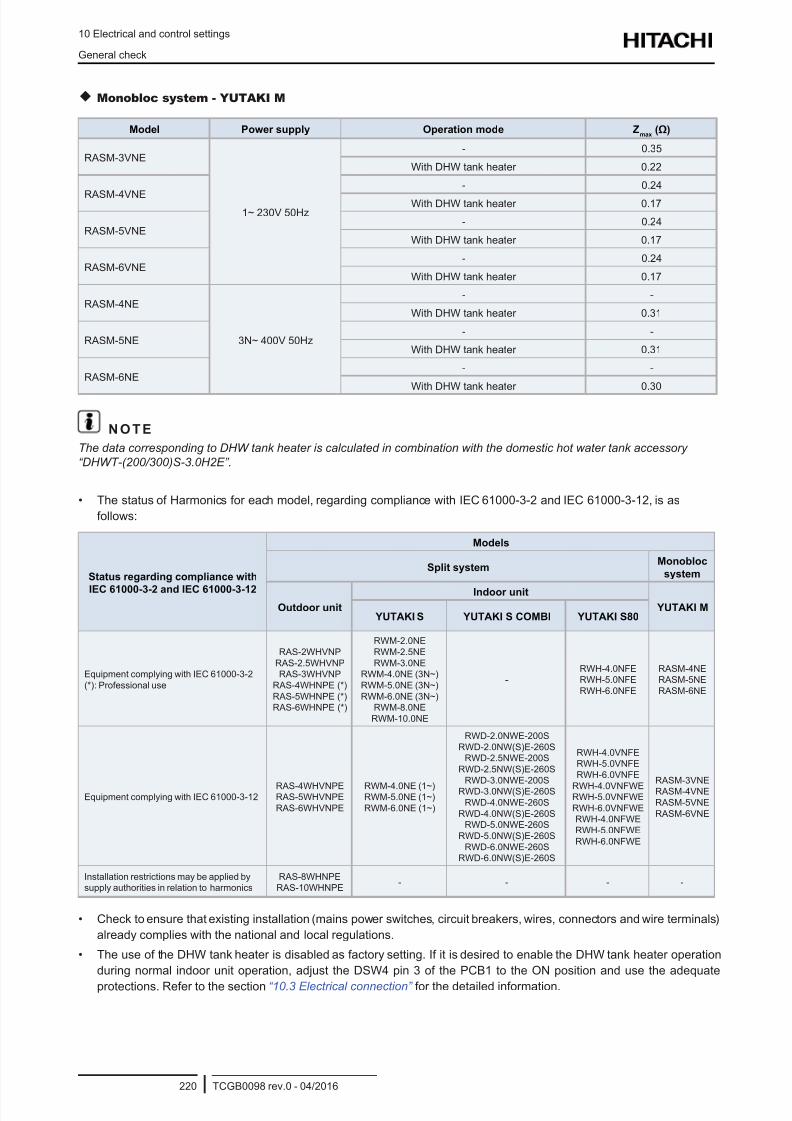
8/16/2019 Hitachi Yutaki Series 2016 Αντλίες θερμότητας
http://slidepdf.com/reader/full/hitachi-yutaki-series-2016- 230/256
10 Electrical and control settings
General check
TCGB0098 rev.0 - 04/2016220
Monobloc system - YUTAKI M
Model Power supply Operation mode Zmax
(Ω)
RASM-3VNE
1~ 230V 50Hz
- 0.35
With DHW tank heater 0.22
RASM-4VNE
- 0.24
With DHW tank heater 0.17
RASM-5VNE- 0.24
With DHW tank heater 0.17
RASM-6VNE- 0.24
With DHW tank heater 0.17
RASM-4NE
3N~ 400V 50Hz
- -
With DHW tank heater 0.31
RASM-5NE- -
With DHW tank heater 0.31
RASM-6NE- -
With DHW tank heater 0.30
N O T E
The data corresponding to DHW tank heater is calculated in combination with the domestic hot water tank accessory
“DHWT-(200/300)S-3.0H2E”.
• The status of Harmonics for each model, regarding compliance with IEC 61000-3-2 and IEC 61000-3-12, is as
follows:
Status regarding compliance with
IEC 61000-3-2 and IEC 61000-3-12
Models
Split systemMonobloc
system
Outdoor unit
Indoor unit
YUTAKI M YUTAKI S YUTAKI S COMBI YUTAKI S80
Equipment complying with IEC 61000-3-2
(*): Professional use
RAS-2WHVNP
RAS-2.5WHVNP
RAS-3WHVNP
RAS-4WHNPE (*)
RAS-5WHNPE (*)
RAS-6WHNPE (*)
RWM-2.0NE
RWM-2.5NE
RWM-3.0NE
RWM-4.0NE (3N~)
RWM-5.0NE (3N~)
RWM-6.0NE (3N~)
RWM-8.0NE
RWM-10.0NE
-RWH-4.0NFE
RWH-5.0NFE
RWH-6.0NFE
RASM-4NE
RASM-5NE
RASM-6NE
Equipment complying with IEC 61000-3-12RAS-4WHVNPERAS-5WHVNPE
RAS-6WHVNPE
RWM-4.0NE (1~)RWM-5.0NE (1~)
RWM-6.0NE (1~)
RWD-2.0NWE-200S
RWD-2.0NW(S)E-260S
RWD-2.5NWE-200S
RWD-2.5NW(S)E-260S
RWD-3.0NWE-200S
RWD-3.0NW(S)E-260S
RWD-4.0NWE-260S
RWD-4.0NW(S)E-260S
RWD-5.0NWE-260S
RWD-5.0NW(S)E-260S
RWD-6.0NWE-260S
RWD-6.0NW(S)E-260S
RWH-4.0VNFE
RWH-5.0VNFE
RWH-6.0VNFE
RWH-4.0VNFWERWH-5.0VNFWE
RWH-6.0VNFWE
RWH-4.0NFWE
RWH-5.0NFWE
RWH-6.0NFWE
RASM-3VNE
RASM-4VNE
RASM-5VNE
RASM-6VNE
Installation restrictions may be applied by
supply authorities in relation to harmonics
RAS-8WHNPE
RAS-10WHNPE- - - -
• Check to ensure that existing installation (mains power switches, circuit breakers, wires, connectors and wire terminals)
already complies with the national and local regulations.
• The use of the DHW tank heater is disabled as factory setting. If it is desired to enable the DHW tank heater operation
during normal indoor unit operation, adjust the DSW4 pin 3 of the PCB1 to the ON position and use the adequate
protections. Refer to the section “10.3 Electrical connection” for the detailed information.
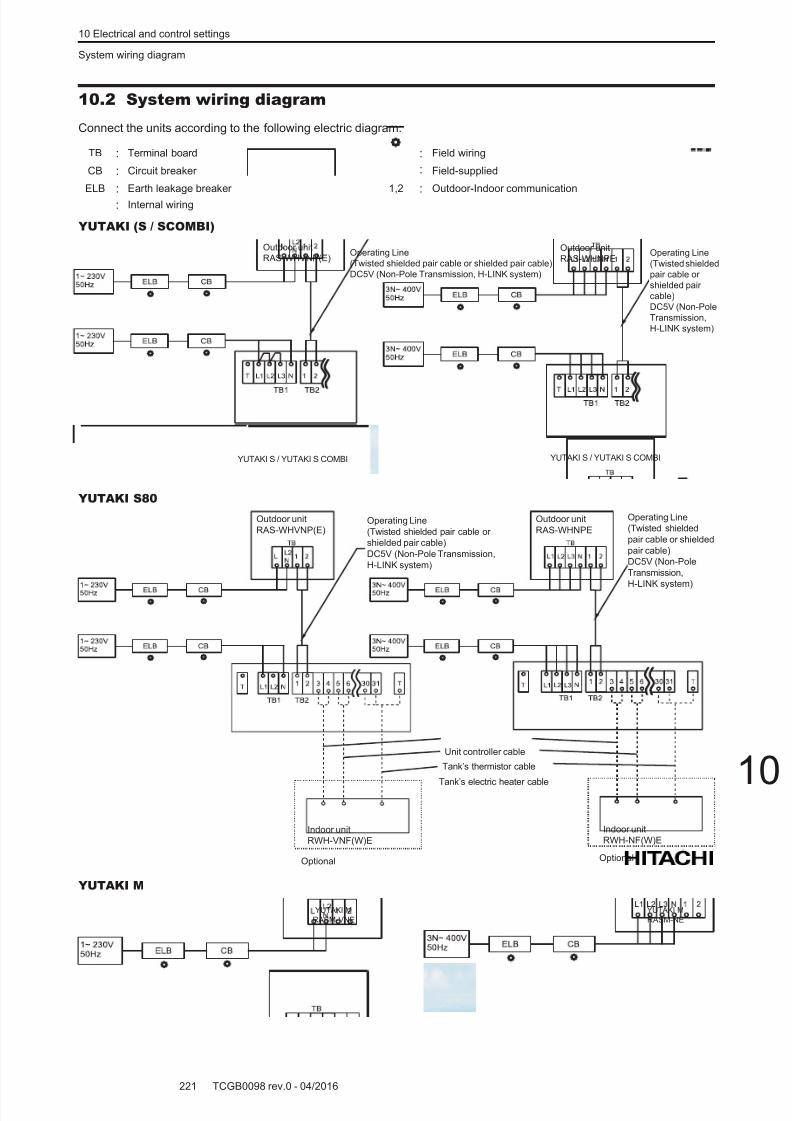
8/16/2019 Hitachi Yutaki Series 2016 Αντλίες θερμότητας
http://slidepdf.com/reader/full/hitachi-yutaki-series-2016- 231/256
10 Electrical and control settings
System wiring diagram
TCGB0098 rev.0 - 04/2016221
10
10.2 System wiring diagram
Connect the units according to the following electric diagram:
TB : Terminal board : Field wiring
CB : Circuit breaker : Field-supplied
ELB : Earth leakage breaker 1,2 : Outdoor-Indoor communication
: Internal wiring
YUTAKI (S / SCOMBI)
Operating Line
(Twisted shielded pair cable or shielded pair cable)
DC5V (Non-Pole Transmission, H-LINK system)
Outdoor unit
RAS-WHVNP(E)
YUTAKI S / YUTAKI S COMBI YUTAKI S / YUTAKI S COMBI
Outdoor unit
RAS-WHNPEOperating Line
(Twisted shielded
pair cable or
shielded pair
cable)
DC5V (Non-Pole
Transmission,
H-LINK system)
YUTAKI S80
Operating Line
(Twisted shielded
pair cable or shielded
pair cable)
DC5V (Non-Pole
Transmission,
H-LINK system)
Operating Line
(Twisted shielded pair cable or
shielded pair cable)
DC5V (Non-Pole Transmission,
H-LINK system)
Optional Optional
Tank’s thermistor cable
Tank’s electric heater cable
Unit controller cable
Outdoor unit
RAS-WHVNP(E)
Outdoor unit
RAS-WHNPE
Indoor unit
RWH-VNF(W)E
Indoor unit
RWH-NF(W)E
YUTAKI M
YUTAKI M
RASM-VNE
YUTAKI M
RASM-NE
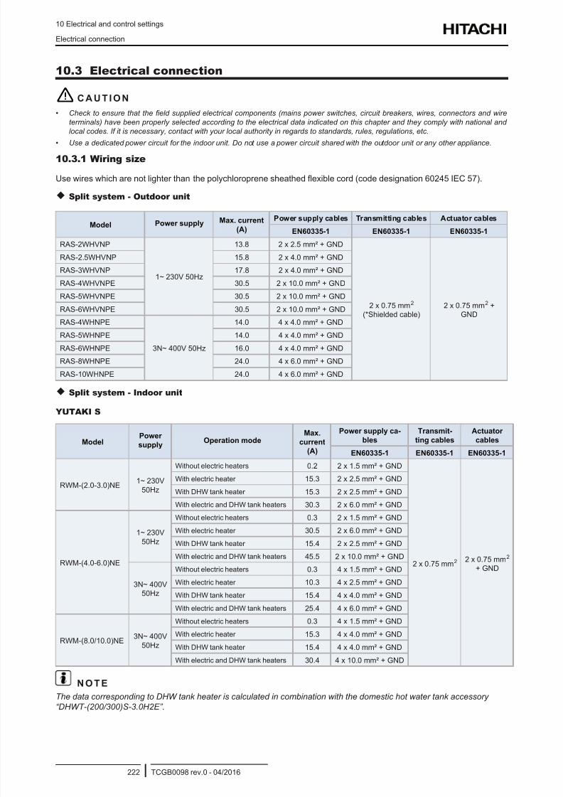
8/16/2019 Hitachi Yutaki Series 2016 Αντλίες θερμότητας
http://slidepdf.com/reader/full/hitachi-yutaki-series-2016- 232/256
10 Electrical and control settings
Electrical connection
TCGB0098 rev.0 - 04/2016222
10.3 Electrical connection
! C A U T I O N
• Check to ensure that the eld supplied electrical components (mains power switches, circuit breakers, wires, connectors and wire
terminals) have been properly selected according to the electrical data indicated on this chapter and they comply with national and
local codes. If it is necessary, contact with your local authority in regards to standards, rules, regulations, etc.
• Use a dedicated power circuit for the indoor unit. Do not use a power circuit shared with the outdoor unit or any other appliance.
10.3.1 Wiring size
Use wires which are not lighter than the polychloroprene sheathed exible cord (code designation 60245 IEC 57).
Split system - Outdoor unit
Model Power supply Max. current
(A)
Power supply cables Transmitting cables Actuator cables
EN60335-1 EN60335-1 EN60335-1
RAS-2WHVNP
1~ 230V 50Hz
13.8 2 x 2.5 mm² + GND
2 x 0.75 mm2
(*Shielded cable)
2 x 0.75 mm2 +
GND
RAS-2.5WHVNP 15.8 2 x 4.0 mm² + GND
RAS-3WHVNP 17.8 2 x 4.0 mm² + GND
RAS-4WHVNPE 30.5 2 x 10.0 mm² + GND
RAS-5WHVNPE 30.5 2 x 10.0 mm² + GND
RAS-6WHVNPE 30.5 2 x 10.0 mm² + GND
RAS-4WHNPE
3N~ 400V 50Hz
14.0 4 x 4.0 mm² + GND
RAS-5WHNPE 14.0 4 x 4.0 mm² + GND
RAS-6WHNPE 16.0 4 x 4.0 mm² + GND
RAS-8WHNPE 24.0 4 x 6.0 mm² + GND
RAS-10WHNPE 24.0 4 x 6.0 mm² + GND
Split system - Indoor unit
YUTAKI S
ModelPower
supplyOperation mode
Max.
current
(A)
Power supply ca-
bles
Transmit-
ting cables
Actuator
cables
EN60335-1 EN60335-1 EN60335-1
RWM-(2.0-3.0)NE1~ 230V
50Hz
Without electric heaters 0.2 2 x 1.5 mm² + GND
2 x 0.75 mm2 2 x 0.75 mm2 + GND
With electric heater 15.3 2 x 2.5 mm² + GND
With DHW tank heater 15.3 2 x 2.5 mm² + GND
With electric and DHW tank heaters 30.3 2 x 6.0 mm² + GND
RWM-(4.0-6.0)NE
1~ 230V
50Hz
Without electric heaters 0.3 2 x 1.5 mm² + GND
With electric heater 30.5 2 x 6.0 mm² + GND
With DHW tank heater 15.4 2 x 2.5 mm² + GND
With electric and DHW tank heaters 45.5 2 x 10.0 mm² + GND
3N~ 400V
50Hz
Without electric heaters 0.3 4 x 1.5 mm² + GND
With electric heater 10.3 4 x 2.5 mm² + GND
With DHW tank heater 15.4 4 x 4.0 mm² + GND
With electric and DHW tank heaters 25.4 4 x 6.0 mm² + GND
RWM-(8.0/10.0)NE3N~ 400V
50Hz
Without electric heaters 0.3 4 x 1.5 mm² + GND
With electric heater 15.3 4 x 4.0 mm² + GND
With DHW tank heater 15.4 4 x 4.0 mm² + GND
With electric and DHW tank heaters 30.4 4 x 10.0 mm² + GND
N O T E
The data corresponding to DHW tank heater is calculated in combination with the domestic hot water tank accessory“DHWT-(200/300)S-3.0H2E”.
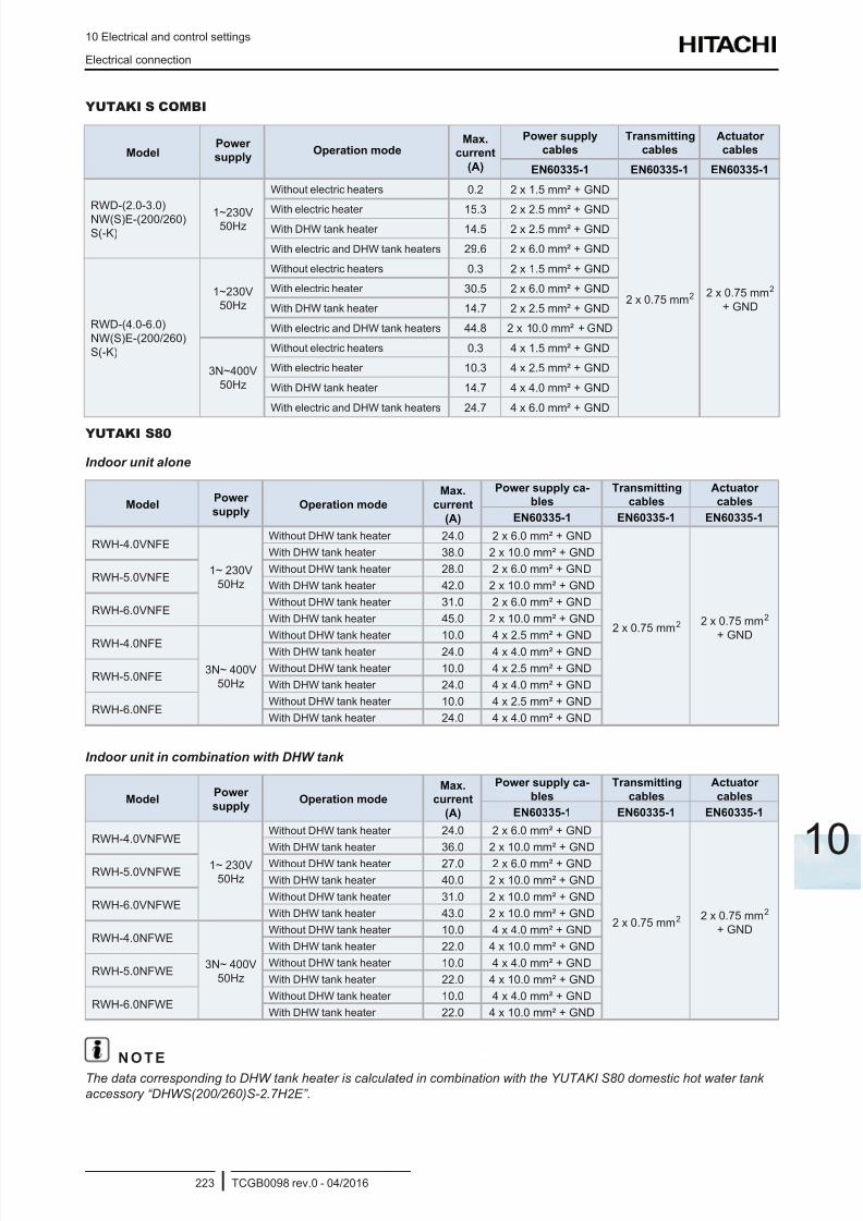
8/16/2019 Hitachi Yutaki Series 2016 Αντλίες θερμότητας
http://slidepdf.com/reader/full/hitachi-yutaki-series-2016- 233/256
10 Electrical and control settings
Electrical connection
TCGB0098 rev.0 - 04/2016223
10
YUTAKI S COMBI
ModelPower
supplyOperation mode
Max.
current
(A)
Power supply
cables
Transmitting
cables
Actuator
cables
EN60335-1 EN60335-1 EN60335-1
RWD-(2.0-3.0)
NW(S)E-(200/260)
S(-K)
1~230V50Hz
Without electric heaters 0.2 2 x 1.5 mm² + GND
2 x 0.75 mm2 2 x 0.75 mm2
+ GND
With electric heater 15.3 2 x 2.5 mm² + GNDWith DHW tank heater 14.5 2 x 2.5 mm² + GND
With electric and DHW tank heaters 29.6 2 x 6.0 mm² + GND
RWD-(4.0-6.0)
NW(S)E-(200/260)
S(-K)
1~230V
50Hz
Without electric heaters 0.3 2 x 1.5 mm² + GND
With electric heater 30.5 2 x 6.0 mm² + GND
With DHW tank heater 14.7 2 x 2.5 mm² + GND
With electric and DHW tank heaters 44.8 2 x 10.0 mm² + GND
3N~400V
50Hz
Without electric heaters 0.3 4 x 1.5 mm² + GND
With electric heater 10.3 4 x 2.5 mm² + GND
With DHW tank heater 14.7 4 x 4.0 mm² + GND
With electric and DHW tank heaters 24.7 4 x 6.0 mm² + GND
YUTAKI S80
Indoor unit alone
ModelPower
supplyOperation mode
Max.
current
(A)
Power supply ca-
bles
Transmitting
cables
Actuator
cables
EN60335-1 EN60335-1 EN60335-1
RWH-4.0VNFE
1~ 230V
50Hz
Without DHW tank heater 24.0 2 x 6.0 mm² + GND
2 x 0.75 mm2 2 x 0.75 mm2
+ GND
With DHW tank heater 38.0 2 x 10.0 mm² + GND
RWH-5.0VNFEWithout DHW tank heater 28.0 2 x 6.0 mm² + GND
With DHW tank heater 42.0 2 x 10.0 mm² + GND
RWH-6.0VNFEWithout DHW tank heater 31.0 2 x 6.0 mm² + GND
With DHW tank heater 45.0 2 x 10.0 mm² + GND
RWH-4.0NFE
3N~ 400V
50Hz
Without DHW tank heater 10.0 4 x 2.5 mm² + GND
With DHW tank heater 24.0 4 x 4.0 mm² + GND
RWH-5.0NFEWithout DHW tank heater 10.0 4 x 2.5 mm² + GND
With DHW tank heater 24.0 4 x 4.0 mm² + GND
RWH-6.0NFEWithout DHW tank heater 10.0 4 x 2.5 mm² + GND
With DHW tank heater 24.0 4 x 4.0 mm² + GND
Indoor unit in combination with DHW tank
ModelPower
supplyOperation mode
Max.
current
(A)
Power supply ca-
bles
Transmitting
cables
Actuator
cables
EN60335-1 EN60335-1 EN60335-1
RWH-4.0VNFWE
1~ 230V
50Hz
Without DHW tank heater 24.0 2 x 6.0 mm² + GND
2 x 0.75 mm2 2 x 0.75 mm2
+ GND
With DHW tank heater 36.0 2 x 10.0 mm² + GND
RWH-5.0VNFWEWithout DHW tank heater 27.0 2 x 6.0 mm² + GND
With DHW tank heater 40.0 2 x 10.0 mm² + GND
RWH-6.0VNFWEWithout DHW tank heater 31.0 2 x 10.0 mm² + GND
With DHW tank heater 43.0 2 x 10.0 mm² + GND
RWH-4.0NFWE
3N~ 400V
50Hz
Without DHW tank heater 10.0 4 x 4.0 mm² + GND
With DHW tank heater 22.0 4 x 10.0 mm² + GND
RWH-5.0NFWEWithout DHW tank heater 10.0 4 x 4.0 mm² + GND
With DHW tank heater 22.0 4 x 10.0 mm² + GND
RWH-6.0NFWEWithout DHW tank heater 10.0 4 x 4.0 mm² + GND
With DHW tank heater 22.0 4 x 10.0 mm² + GND
N O T E
The data corresponding to DHW tank heater is calculated in combination with the YUTAKI S80 domestic hot water tank
accessory “DHWS(200/260)S-2.7H2E”.
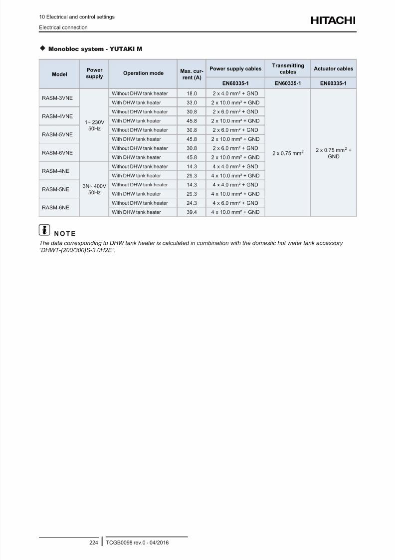
8/16/2019 Hitachi Yutaki Series 2016 Αντλίες θερμότητας
http://slidepdf.com/reader/full/hitachi-yutaki-series-2016- 234/256
10 Electrical and control settings
Electrical connection
TCGB0098 rev.0 - 04/2016224
Monobloc system - YUTAKI M
ModelPower
supplyOperation mode Max. cur-
rent (A)
Power supply cablesTransmitting
cablesActuator cables
EN60335-1 EN60335-1 EN60335-1
RASM-3VNE
1~ 230V
50Hz
Without DHW tank heater 18.0 2 x 4.0 mm² + GND
2 x 0.75 mm2 2 x 0.75 mm2 +
GND
With DHW tank heater 33.0 2 x 10.0 mm² + GND
RASM-4VNEWithout DHW tank heater 30.8 2 x 6.0 mm² + GND
With DHW tank heater 45.8 2 x 10.0 mm² + GND
RASM-5VNEWithout DHW tank heater 30.8 2 x 6.0 mm² + GND
With DHW tank heater 45.8 2 x 10.0 mm² + GND
RASM-6VNEWithout DHW tank heater 30.8 2 x 6.0 mm² + GND
With DHW tank heater 45.8 2 x 10.0 mm² + GND
RASM-4NE
3N~ 400V
50Hz
Without DHW tank heater 14.3 4 x 4.0 mm² + GND
With DHW tank heater 29.3 4 x 10.0 mm² + GND
RASM-5NEWithout DHW tank heater 14.3 4 x 4.0 mm² + GND
With DHW tank heater 29.3 4 x 10.0 mm² + GND
RASM-6NEWithout DHW tank heater 24.3 4 x 6.0 mm² + GND
With DHW tank heater 39.4 4 x 10.0 mm² + GND
N O T E
The data corresponding to DHW tank heater is calculated in combination with the domestic hot water tank accessory
“DHWT-(200/300)S-3.0H2E”.
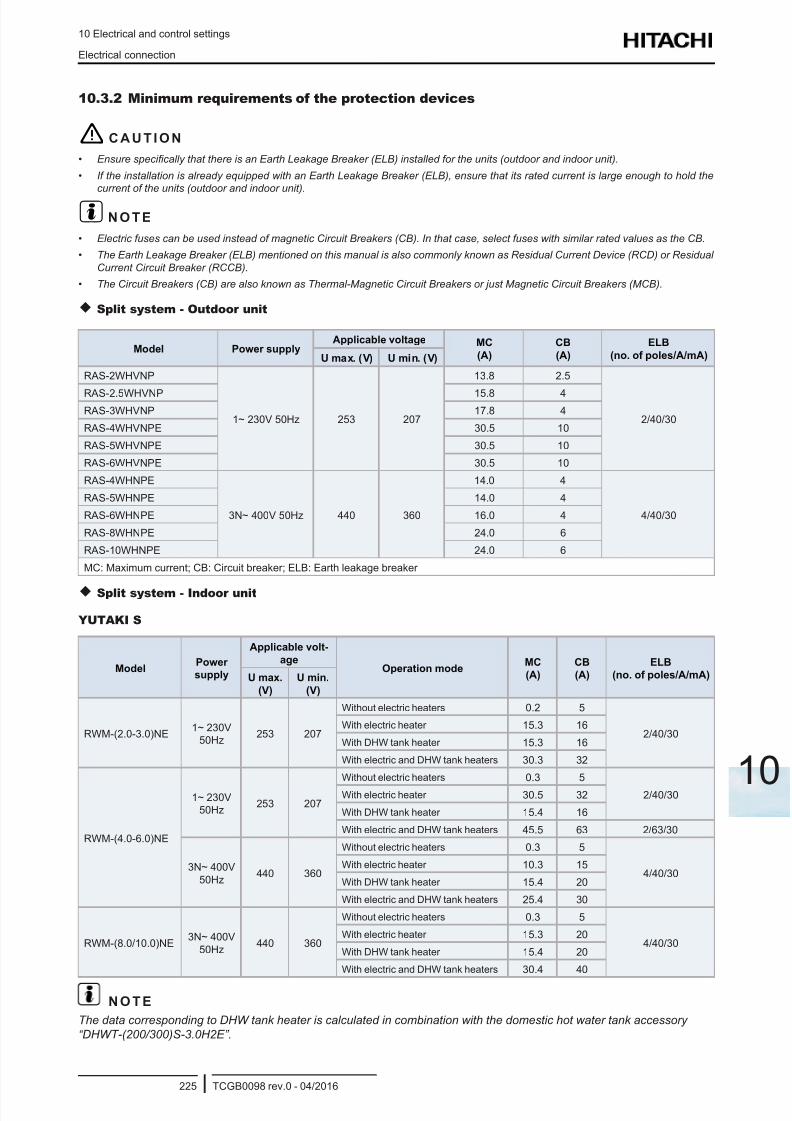
8/16/2019 Hitachi Yutaki Series 2016 Αντλίες θερμότητας
http://slidepdf.com/reader/full/hitachi-yutaki-series-2016- 235/256
10 Electrical and control settings
Electrical connection
TCGB0098 rev.0 - 04/2016225
10
10.3.2 Minimum requirements of the protection devices
! C A U T I O N
• Ensure specically that there is an Earth Leakage Breaker (ELB) installed for the units (outdoor and indoor unit).
• If the installation is already equipped with an Earth Leakage Breaker (ELB), ensure that its rated current is large enough to hold the
current of the units (outdoor and indoor unit).
? N O T E
• Electric fuses can be used instead of magnetic Circuit Breakers (CB). In that case, select fuses with similar rated values as the CB.
• The Earth Leakage Breaker (ELB) mentioned on this manual is also commonly known as Residual Current Device (RCD) or Residual
Current Circuit Breaker (RCCB).
• The Circuit Breakers (CB) are also known as Thermal-Magnetic Circuit Breakers or just Magnetic Circuit Breakers (MCB).
Split system - Outdoor unit
Model Power supplyApplicable voltage MC
(A)
CB
(A)
ELB
(no. of poles/A/mA)U max. (V) U min. (V)
RAS-2WHVNP
1~ 230V 50Hz 253 207
13.8 2.5
2/40/30
RAS-2.5WHVNP 15.8 4
RAS-3WHVNP 17.8 4
RAS-4WHVNPE 30.5 10
RAS-5WHVNPE 30.5 10
RAS-6WHVNPE 30.5 10
RAS-4WHNPE
3N~ 400V 50Hz 440 360
14.0 4
4/40/30
RAS-5WHNPE 14.0 4
RAS-6WHNPE 16.0 4
RAS-8WHNPE 24.0 6
RAS-10WHNPE 24.0 6
MC: Maximum current; CB: Circuit breaker; ELB: Earth leakage breaker
Split system - Indoor unit
YUTAKI S
ModelPower
supply
Applicable volt-
ageOperation mode
MC
(A)
CB
(A)
ELB
(no. of poles/A/mA)U max.
(V)
U min.
(V)
RWM-(2.0-3.0)NE1~ 230V
50Hz253 207
Without electric heaters 0.2 5
2/40/30With electric heater 15.3 16
With DHW tank heater 15.3 16
With electric and DHW tank heaters 30.3 32
RWM-(4.0-6.0)NE
1~ 230V
50Hz253 207
Without electric heaters 0.3 5
2/40/30With electric heater 30.5 32
With DHW tank heater 15.4 16
With electric and DHW tank heaters 45.5 63 2/63/30
3N~ 400V
50Hz440 360
Without electric heaters 0.3 5
4/40/30With electric heater 10.3 15
With DHW tank heater 15.4 20
With electric and DHW tank heaters 25.4 30
RWM-(8.0/10.0)NE3N~ 400V
50Hz440 360
Without electric heaters 0.3 5
4/40/30With electric heater 15.3 20
With DHW tank heater 15.4 20
With electric and DHW tank heaters 30.4 40
N O T E
The data corresponding to DHW tank heater is calculated in combination with the domestic hot water tank accessory
“DHWT-(200/300)S-3.0H2E”.
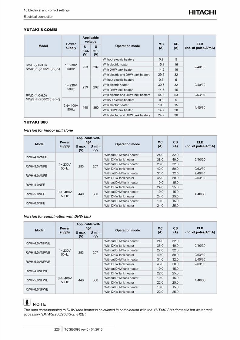
8/16/2019 Hitachi Yutaki Series 2016 Αντλίες θερμότητας
http://slidepdf.com/reader/full/hitachi-yutaki-series-2016- 236/256
10 Electrical and control settings
Electrical connection
TCGB0098 rev.0 - 04/2016226
YUTAKI S COMBI
ModelPower
supply
Applicable
voltage
Operation modeMC
(A)
CB
(A)
ELB
(no. of poles/A/mA)U
max.
(V)
U
min.
(V)
RWD-(2.0-3.0)
NW(S)E-(200/260)S(-K)
1~ 230V
50Hz253 207
Without electric heaters 0.2 5
2/40/30With electric heater 15.3 16
With DHW tank heater 14.5 16
With electric and DHW tank heaters 29.6 32
RWD-(4.0-6.0)
NW(S)E-(200/260)S(-K)
1~ 230V
50Hz253 207
Without electric heaters 0.3 5
2/40/30With electric heater 30.5 32
With DHW tank heater 14.7 16
With electric and DHW tank heaters 44.8 63 2/63/30
3N~ 400V
50Hz440 360
Without electric heaters 0.3 5
4/40/30With electric heater 10.3 15
With DHW tank heater 14.7 20
With electric and DHW tank heaters 24.7 30
YUTAKI S80
Version for indoor unit alone
ModelPower
supply
Applicable volt-
ageOperation mode
MC
(A)
CB
(A)
ELB
(no. of poles/A/mA)U max.
(V)
U min.
(V)
RWH-4.0VNFE
1~ 230V
50Hz253 207
Without DHW tank heater 24.0 32.0
2/40/30With DHW tank heater 38.0 40.0
RWH-5.0VNFEWithout DHW tank heater 28.0 32.0
With DHW tank heater 42.0 50.0 2/63/30
RWH-6.0VNFEWithout DHW tank heater 31.0 32.0 2/40/30
With DHW tank heater 45.0 50.0 2/63/30
RWH-4.0NFE
3N~ 400V
50Hz440 360
Without DHW tank heater 10.0 15.0
4/40/30
With DHW tank heater 24.0 25.0
RWH-5.0NFEWithout DHW tank heater 10.0 15.0
With DHW tank heater 24.0 25.0
RWH-6.0NFEWithout DHW tank heater 10.0 15.0
With DHW tank heater 24.0 25.0
Version for combination with DHW tank
ModelPower
supply
Applicable volt-
ageOperation mode
MC
(A)
CB
(A)
ELB
(no. of poles/A/mA)U max.
(V)
U min.
(V)
RWH-4.0VNFWE
1~ 230V
50Hz253 207
Without DHW tank heater 24.0 32.0
2/40/30With DHW tank heater 36.0 40.0
RWH-5.0VNFWEWithout DHW tank heater 27.0 32.0
With DHW tank heater 40.0 50.0 2/63/30
RWH-6.0VNFWEWithout DHW tank heater 31.0 32.0 2/40/30
With DHW tank heater 43.0 50.0 2/63/30
RWH-4.0NFWE
3N~ 400V
50Hz440 360
Without DHW tank heater 10.0 15.0
4/40/30
With DHW tank heater 22.0 25.0
RWH-5.0NFWEWithout DHW tank heater 10.0 15.0
With DHW tank heater 22.0 25.0
RWH-6.0NFWEWithout DHW tank heater 10.0 15.0
With DHW tank heater 22.0 25.0
N O T E
The data corresponding to DHW tank heater is calculated in combination with the YUTAKI S80 domestic hot water tank
accessory “DHWS(200/260)S-2.7H2E”.
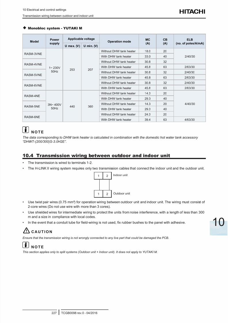
8/16/2019 Hitachi Yutaki Series 2016 Αντλίες θερμότητας
http://slidepdf.com/reader/full/hitachi-yutaki-series-2016- 237/256
10 Electrical and control settings
Transmission wiring between outdoor and indoor unit
TCGB0098 rev.0 - 04/2016227
10
Monobloc system - YUTAKI M
ModelPower
supply
Applicable voltageOperation mode
MC
(A)
CB
(A)
ELB
(no. of poles/A/mA)U max. (V) U min. (V)
RASM-3VNE
1~ 230V
50Hz253 207
Without DHW tank heater 18.0 20
2/40/30With DHW tank heater 33.0 40
RASM-4VNEWithout DHW tank heater 30.8 32
With DHW tank heater 45.8 63 2/63/30
RASM-5VNEWithout DHW tank heater 30.8 32 2/40/30
With DHW tank heater 45.8 63 2/63/30
RASM-6VNEWithout DHW tank heater 30.8 32 2/40/30
With DHW tank heater 45.8 63 2/63/30
RASM-4NE
3N~ 400V
50Hz440 360
Without DHW tank heater 14.3 20
4/40/30
With DHW tank heater 29.3 40
RASM-5NEWithout DHW tank heater 14.3 20
With DHW tank heater 29.3 40
RASM-6NEWithout DHW tank heater 24.3 20
With DHW tank heater 39.4 63 4/63/30
N O T E
The data corresponding to DHW tank heater is calculated in combination with the domestic hot water tank accessory
“DHWT-(200/300)S-3.0H2E”.
10.4 Transmission wiring between outdoor and indoor unit
• The transmission is wired to terminals 1-2.
• The H-LINK II wiring system requires only two transmission cables that connect the indoor unit and the outdoor unit.
1
1
2
2
Indoor unit
Outdoor unit
• Use twist pair wires (0.75 mm²) for operation wiring between outdoor unit and indoor unit. The wiring must consist of
2-core wires (Do not use wire with more than 3 cores).
• Use shielded wires for intermediate wiring to protect the units from noise interference, with a length of less than 300
m and a size in compliance with local codes.
• In the event that a conduit tube for eld-wiring is not used, x rubber bushes to the panel with adhesive.
! C A U T I O N
Ensure that the transmission wiring is not wrongly connected to any live part that could be damaged the PCB.
N O T E
This section applies only to split systems (Outdoor unit + Indoor unit). It does not apply to YUTAKI M.
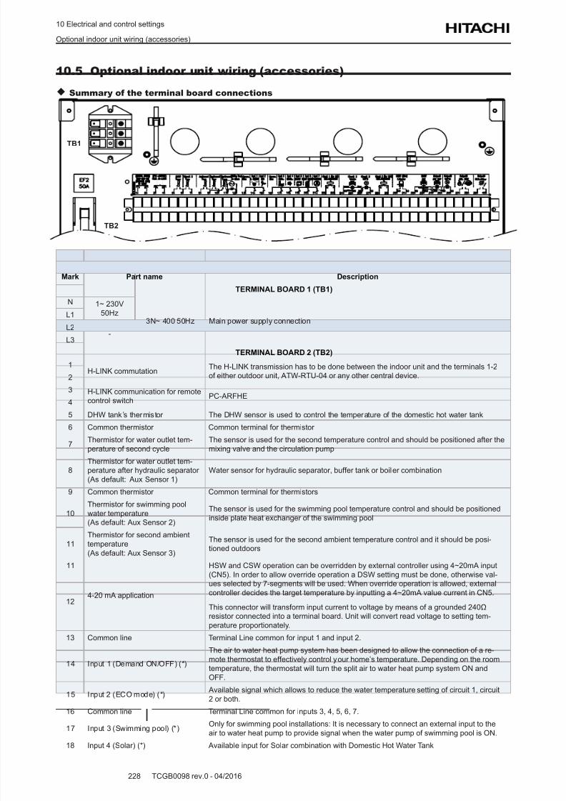
8/16/2019 Hitachi Yutaki Series 2016 Αντλίες θερμότητας
http://slidepdf.com/reader/full/hitachi-yutaki-series-2016- 238/256
10 Electrical and control settings
Optional indoor unit wiring (accessories)
TCGB0098 rev.0 - 04/2016228
10.5 Optional indoor unit wiring (accessories)
Summary of the terminal board connections
TB2
TB1
Mark Part name DescriptionTERMINAL BOARD 1 (TB1)
N 1~ 230V
50Hz3N~ 400 50Hz Main power supply connection
L1
L2-
L3
TERMINAL BOARD 2 (TB2)
1H-LINK commutation
The H-LINK transmission has to be done between the indoor unit and the terminals 1-2
of either outdoor unit, ATW-RTU-04 or any other central device.2
3 H-LINK communication for remote
control switchPC-ARFHE
4
5 DHW tank’s thermistor The DHW sensor is used to control the temperature of the domestic hot water tank
6 Common thermistor Common terminal for thermistor
7Thermistor for water outlet tem-
perature of second cycle
The sensor is used for the second temperature control and should be positioned after the
mixing valve and the circulation pump
8
Thermistor for water outlet tem-
perature after hydraulic separator
(As default: Aux Sensor 1)
Water sensor for hydraulic separator, buffer tank or boiler combination
9 Common thermistor Common terminal for thermistors
10
Thermistor for swimming pool
water temperature
(As default: Aux Sensor 2)
The sensor is used for the swimming pool temperature control and should be positioned
inside plate heat exchanger of the swimming pool
11
Thermistor for second ambient
temperature
(As default: Aux Sensor 3)
The sensor is used for the second ambient temperature control and it should be posi-
tioned outdoors
11
4-20 mA application
HSW and CSW operation can be overridden by external controller using 4~20mA input
(CN5). In order to allow override operation a DSW setting must be done, otherwise val-
ues selected by 7-segments will be used. When override operation is allowed, external
controller decides the target temperature by inputting a 4~20mA value current in CN5.
This connector will transform input current to voltage by means of a grounded 240Ω
resistor connected into a terminal board. Unit will convert read voltage to setting tem-
perature proportionately.
12
13 Common line Terminal Line common for input 1 and input 2.
14 Input 1 (Demand ON/OFF) (*)
The air to water heat pump system has been designed to allow the connection of a re-
mote thermostat to effectively control your home’s temperature. Depending on the room
temperature, the thermostat will turn the split air to water heat pump system ON and
OFF.
15 Input 2 (ECO mode) (*) Available signal which allows to reduce the water temperature setting of circuit 1, circuit
2 or both.16 Common line Terminal Line common for inputs 3, 4, 5, 6, 7.
17 Input 3 (Swimming pool) (*)Only for swimming pool installations: It is necessary to connect an external input to the
air to water heat pump to provide signal when the water pump of swimming pool is ON.
18 Input 4 (Solar) (*) Available input for Solar combination with Domestic Hot Water Tank
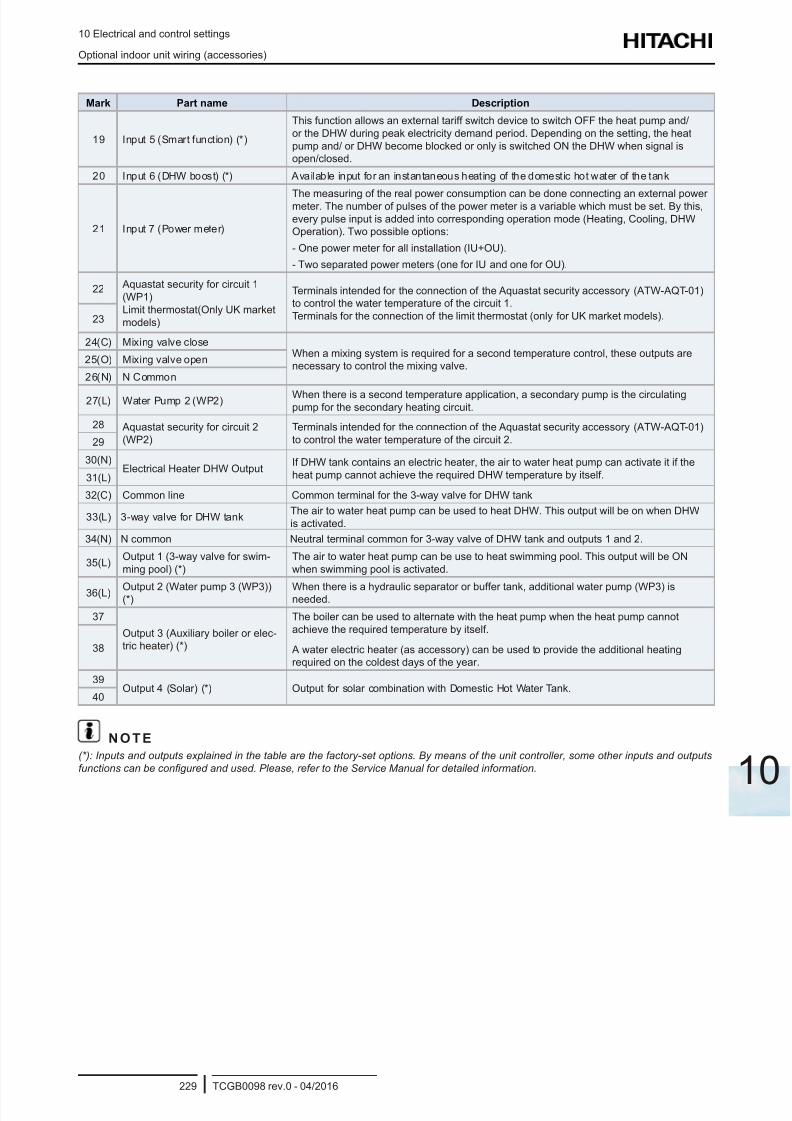
8/16/2019 Hitachi Yutaki Series 2016 Αντλίες θερμότητας
http://slidepdf.com/reader/full/hitachi-yutaki-series-2016- 239/256
10 Electrical and control settings
Optional indoor unit wiring (accessories)
TCGB0098 rev.0 - 04/2016229
10
Mark Part name Description
19 Input 5 (Smart function) (*)
This function allows an external tariff switch device to switch OFF the heat pump and/
or the DHW during peak electricity demand period. Depending on the setting, the heat
pump and/ or DHW become blocked or only is switched ON the DHW when signal is
open/closed.
20 Input 6 (DHW boost) (*) Available input for an instantaneous heating of the domestic hot water of the tank
21 Input 7 (Power meter)
The measuring of the real power consumption can be done connecting an external powermeter. The number of pulses of the power meter is a variable which must be set. By this,
every pulse input is added into corresponding operation mode (Heating, Cooling, DHW
Operation). Two possible options:
- One power meter for all installation (IU+OU).
- Two separated power meters (one for IU and one for OU).
22 Aquastat security for circuit 1
(WP1)
Limit thermostat(Only UK market
models)
Terminals intended for the connection of the Aquastat security accessory (ATW-AQT-01)
to control the water temperature of the circuit 1.
Terminals for the connection of the limit thermostat (only for UK market models).23
24(C) Mixing valve closeWhen a mixing system is required for a second temperature control, these outputs are
necessary to control the mixing valve.25(O) Mixing valve open
26(N) N Common
27(L) Water Pump 2 (WP2) When there is a second temperature application, a secondary pump is the circulatingpump for the secondary heating circuit.
28 Aquastat security for circuit 2
(WP2)
Terminals intended for the connection of the Aquastat security accessory (ATW-AQT-01)
to control the water temperature of the circuit 2.29
30(N)Electrical Heater DHW Output
If DHW tank contains an electric heater, the air to water heat pump can activate it if the
heat pump cannot achieve the required DHW temperature by itself.31(L)
32(C) Common line Common terminal for the 3-way valve for DHW tank
33(L) 3-way valve for DHW tankThe air to water heat pump can be used to heat DHW. This output will be on when DHW
is activated.
34(N) N common Neutral terminal common for 3-way valve of DHW tank and outputs 1 and 2.
35(L)Output 1 (3-way valve for swim-
ming pool) (*)
The air to water heat pump can be use to heat swimming pool. This output will be ON
when swimming pool is activated.
36(L) Output 2 (Water pump 3 (WP3))(*)
When there is a hydraulic separator or buffer tank, additional water pump (WP3) isneeded.
37
Output 3 (Auxiliary boiler or elec-
tric heater) (*)
The boiler can be used to alternate with the heat pump when the heat pump cannot
achieve the required temperature by itself.
A water electric heater (as accessory) can be used to provide the additional heating
required on the coldest days of the year.
38
39Output 4 (Solar) (*) Output for solar combination with Domestic Hot Water Tank.
40
N O T E
(*): Inputs and outputs explained in the table are the factory-set options. By means of the unit controller, some other inputs and outputs
functions can be congured and used. Please, refer to the Service Manual for detailed information.
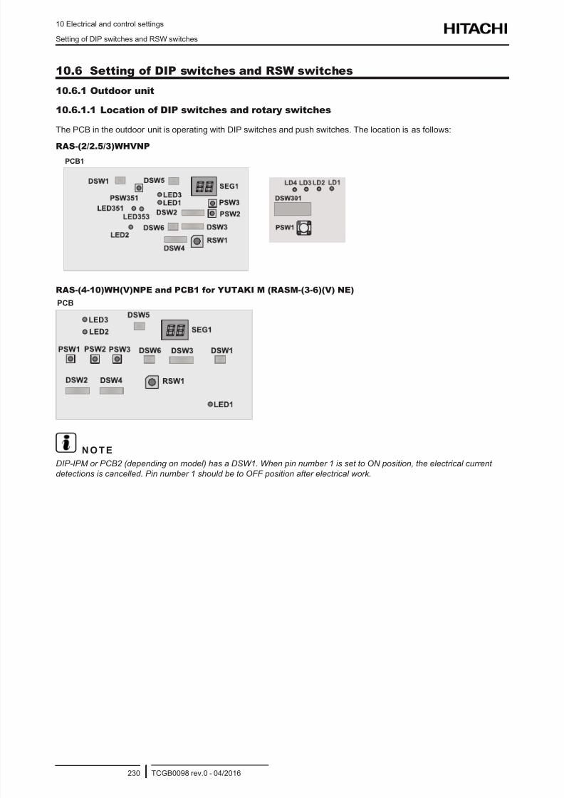
8/16/2019 Hitachi Yutaki Series 2016 Αντλίες θερμότητας
http://slidepdf.com/reader/full/hitachi-yutaki-series-2016- 240/256
10 Electrical and control settings
Setting of DIP switches and RSW switches
TCGB0098 rev.0 - 04/2016230
10.6 Setting of DIP switches and RSW switches
10.6.1 Outdoor unit
10.6.1.1 Location of DIP switches and rotary switches
The PCB in the outdoor unit is operating with DIP switches and push switches. The location is as follows:
RAS-(2/2.5/3)WHVNP
PCB1
RAS-(4-10)WH(V)NPE and PCB1 for YUTAKI M (RASM-(3-6)(V) NE)
PCB
N O T E
DIP-IPM or PCB2 (depending on model) has a DSW1. When pin number 1 is set to ON position, the electrical current
detections is cancelled. Pin number 1 should be to OFF position after electrical work.
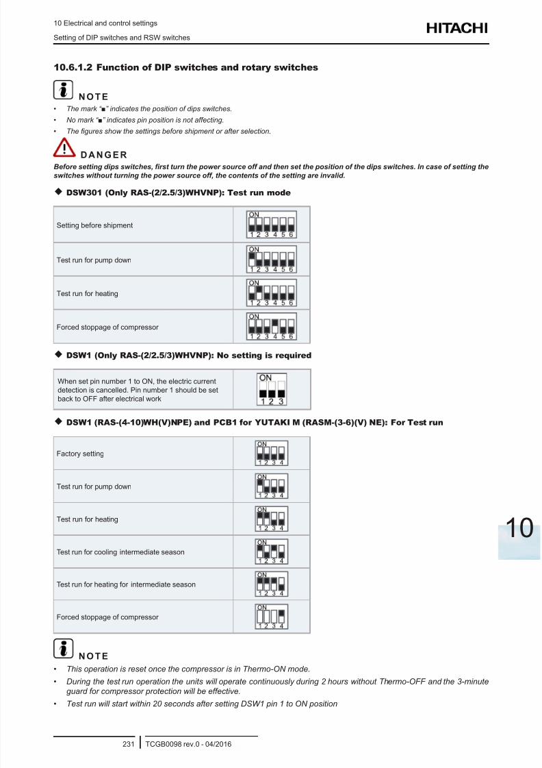
8/16/2019 Hitachi Yutaki Series 2016 Αντλίες θερμότητας
http://slidepdf.com/reader/full/hitachi-yutaki-series-2016- 241/256
10 Electrical and control settings
Setting of DIP switches and RSW switches
TCGB0098 rev.0 - 04/2016231
10
10.6.1.2 Function of DIP switches and rotary switches
N O T E
• The mark “” indicates the position of dips switches.
• No mark “” indicates pin position is not affecting.
• The gures show the settings before shipment or after selection.
D A N G E R
Before setting dips switches, rst turn the power source off and then set the position of the dips switches. In case of setting the
switches without turning the power source off, the contents of the setting are invalid.
DSW301 (Only RAS-(2/2.5/3)WHVNP): Test run mode
Setting before shipment
Test run for pump down
Test run for heating
Forced stoppage of compressor
DSW1 (Only RAS-(2/2.5/3)WHVNP): No setting is required
When set pin number 1 to ON, the electric current
detection is cancelled. Pin number 1 should be set
back to OFF after electrical work
DSW1 (RAS-(4-10)WH(V)NPE) and PCB1 for YUTAKI M (RASM-(3-6)(V) NE): For Test run
Factory setting
Test run for pump down
Test run for heating
Test run for cooling intermediate season
Test run for heating for intermediate season
Forced stoppage of compressor
N O T E
• This operation is reset once the compressor is in Thermo-ON mode.• During the test run operation the units will operate continuously during 2 hours without Thermo-OFF and the 3-minute
guard for compressor protection will be effective.
• Test run will start within 20 seconds after setting DSW1 pin 1 to ON position

8/16/2019 Hitachi Yutaki Series 2016 Αντλίες θερμότητας
http://slidepdf.com/reader/full/hitachi-yutaki-series-2016- 242/256
10 Electrical and control settings
Setting of DIP switches and RSW switches
TCGB0098 rev.0 - 04/2016232
DSW2: selection function
Setting before shipment
Optional function setting mode (The optional function selectionmode becomes available)
External input/output setting mode (The output signals selection
mode becomes available).
DSW3: Capacity setting (No setting is required)
Outdoor unit RAS-(2-10)WH(V)NPE Factory setting
RAS-2WHVNP RAS-2.5WHVNP RAS-3WHVNP RAS-4WHVNPE RAS-5WHVNPE RAS-6WHVNPE
RAS-4WHNPE RAS-5WHNPE RAS-6WHNPE RAS-8WHNPE RAS-10WHNPE
YUTAKI M RASM-(3-6)(V) NE Factory setting
RASM-3VNE RASM-4VNE RASM-5VNE RASM-6VNE
RASM-4NE RASM-5NE RASM-6NE
DSW4 / RSW1: Refrigerant cycle number setting (No setting is required)
Setting before shipment
DSW5: End terminal resistance (No setting is required)
Setting before shipment
DSW6: Additional setting (No setting is required)
Setting before shipment
10.6.1.3 LED indication
LED Indication
LED1 Red This LED indicates the transmission status between the indoor unit and the unit controller
LED2 Yellow This LED indicates the transmission status between the indoor unit and the outdoor unit
LED3 Green Power source for the PCB
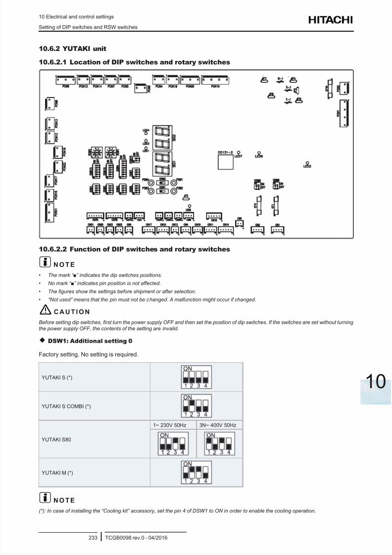
8/16/2019 Hitachi Yutaki Series 2016 Αντλίες θερμότητας
http://slidepdf.com/reader/full/hitachi-yutaki-series-2016- 243/256
10 Electrical and control settings
Setting of DIP switches and RSW switches
TCGB0098 rev.0 - 04/2016233
10
10.6.2 YUTAKI unit
10.6.2.1 Location of DIP switches and rotary switches
10.6.2.2 Function of DIP switches and rotary switches
? N O T E
• The mark “” indicates the dip switches positions.
• No mark “” indicates pin position is not affected.
• The gures show the settings before shipment or after selection.• “Not used” means that the pin must not be changed. A malfunction might occur if changed.
! C A U T I O N
Before setting dip switches, rst turn the power supply OFF and then set the position of dip switches. If the switches are set without turning
the power supply OFF, the contents of the setting are invalid.
DSW1: Additional setting 0
Factory setting. No setting is required.
YUTAKI S (*)
YUTAKI S COMBI (*)
YUTAKI S80
1~ 230V 50Hz 3N~ 400V 50Hz
YUTAKI M (*)
? N O T E
(*): In case of installing the “Cooling kit” accessory, set the pin 4 of DSW1 to ON in order to enable the cooling operation.
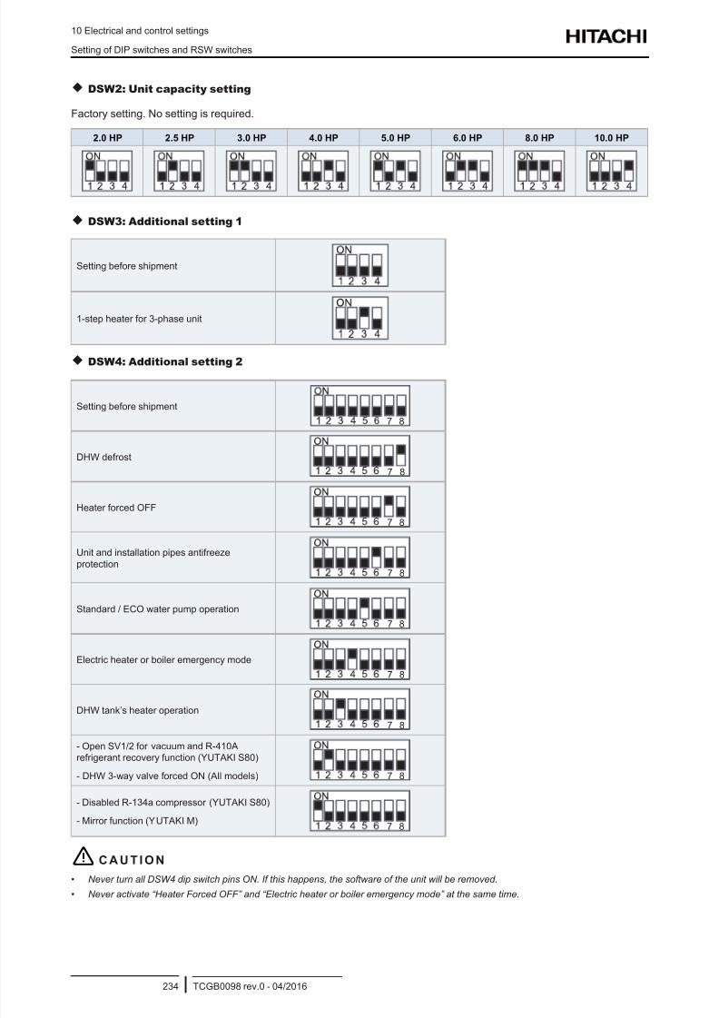
8/16/2019 Hitachi Yutaki Series 2016 Αντλίες θερμότητας
http://slidepdf.com/reader/full/hitachi-yutaki-series-2016- 244/256
10 Electrical and control settings
Setting of DIP switches and RSW switches
TCGB0098 rev.0 - 04/2016234
DSW2: Unit capacity setting
Factory setting. No setting is required.
2.0 HP 2.5 HP 3.0 HP 4.0 HP 5.0 HP 6.0 HP 8.0 HP 10.0 HP
DSW3: Additional setting 1
Setting before shipment
1-step heater for 3-phase unit
DSW4: Additional setting 2
Setting before shipment
87
DHW defrost
87
Heater forced OFF
87
Unit and installation pipes antifreeze
protection87
Standard / ECO water pump operation
87
Electric heater or boiler emergency mode
87
DHW tank’s heater operation87
- Open SV1/2 for vacuum and R-410A
refrigerant recovery function (YUTAKI S80)
- DHW 3-way valve forced ON (All models) 87
- Disabled R-134a compressor (YUTAKI S80)
- Mirror function (YUTAKI M)87
! C A U T I O N
• Never turn all DSW4 dip switch pins ON. If this happens, the software of the unit will be removed.
• Never activate “Heater Forced OFF” and “Electric heater or boiler emergency mode” at the same time.
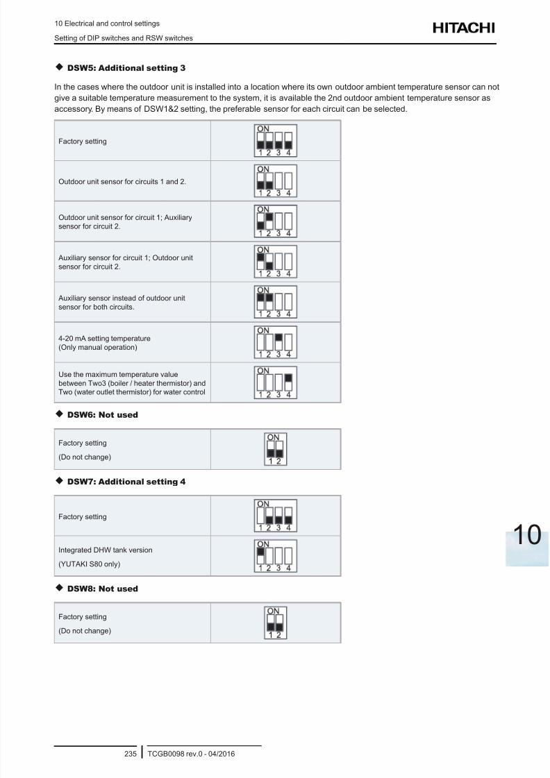
8/16/2019 Hitachi Yutaki Series 2016 Αντλίες θερμότητας
http://slidepdf.com/reader/full/hitachi-yutaki-series-2016- 245/256
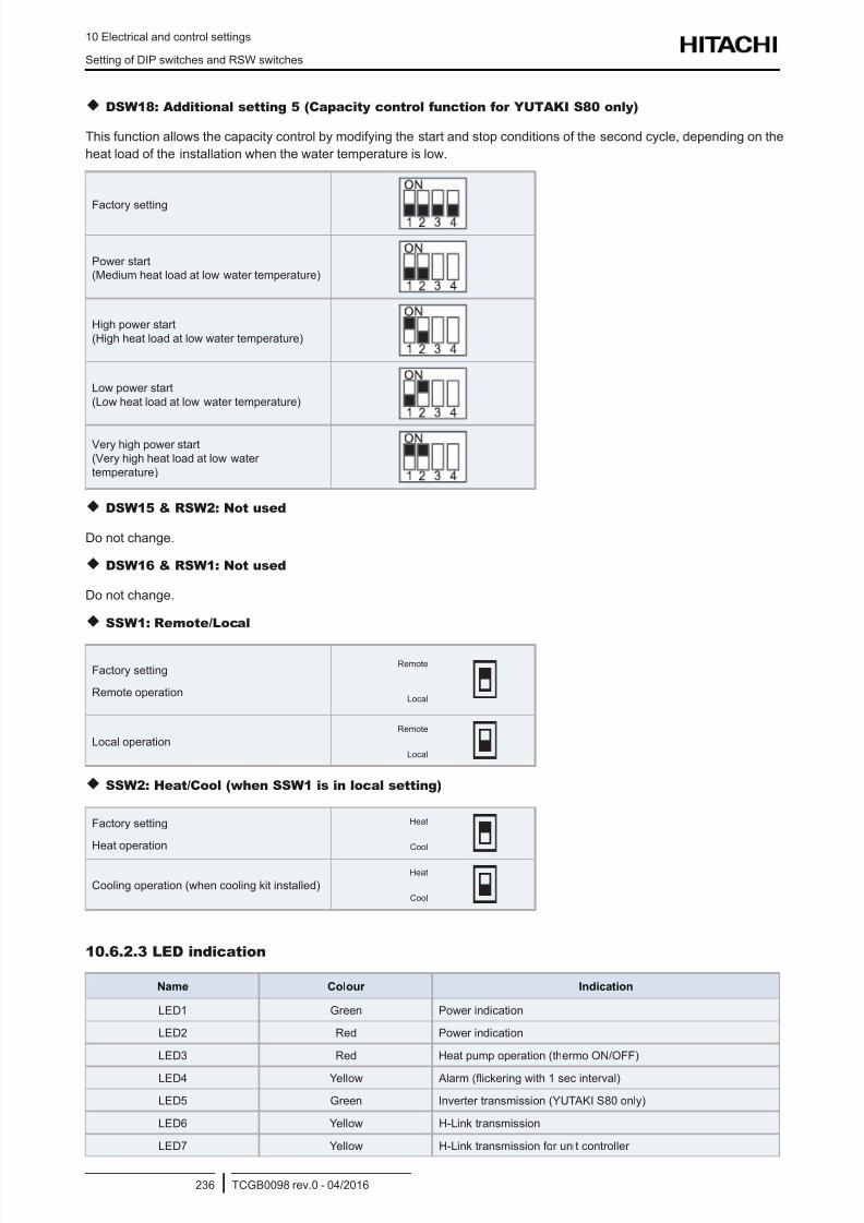
8/16/2019 Hitachi Yutaki Series 2016 Αντλίες θερμότητας
http://slidepdf.com/reader/full/hitachi-yutaki-series-2016- 246/256
10 Electrical and control settings
Setting of DIP switches and RSW switches
TCGB0098 rev.0 - 04/2016236
DSW18: Additional setting 5 (Capacity control function for YUTAKI S80 only)
This function allows the capacity control by modifying the start and stop conditions of the second cycle, depending on the
heat load of the installation when the water temperature is low.
Factory setting
Power start
(Medium heat load at low water temperature)
High power start
(High heat load at low water temperature)
Low power start
(Low heat load at low water temperature)
Very high power start
(Very high heat load at low water
temperature)
DSW15 & RSW2: Not used
Do not change.
DSW16 & RSW1: Not used
Do not change.
SSW1: Remote/Local
Factory setting
Remote operation
Remote
Local
Local operation
Remote
Local
SSW2: Heat/Cool (when SSW1 is in local setting)
Factory setting
Heat operation
Heat
Cool
Cooling operation (when cooling kit installed)
Heat
Cool
10.6.2.3 LED indication
Name Colour Indication
LED1 Green Power indication
LED2 Red Power indication
LED3 Red Heat pump operation (thermo ON/OFF)
LED4 Yellow Alarm (ickering with 1 sec interval)
LED5 Green Inverter transmission (YUTAKI S80 only)
LED6 Yellow H-Link transmission
LED7 Yellow H-Link transmission for unit controller
8/16/2019 Hitachi Yutaki Series 2016 Αντλίες θερμότητας
http://slidepdf.com/reader/full/hitachi-yutaki-series-2016- 247/256
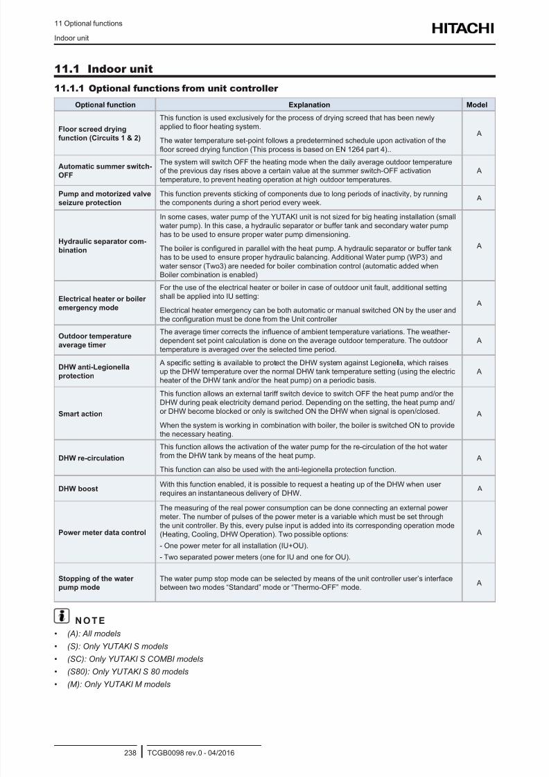
8/16/2019 Hitachi Yutaki Series 2016 Αντλίες θερμότητας
http://slidepdf.com/reader/full/hitachi-yutaki-series-2016- 248/256
11 Optional functions
Indoor unit
TCGB0098 rev.0 - 04/2016238
11.1 Indoor unit
11.1.1 Optional functions from unit controller
Optional function Explanation Model
Floor screed drying
function (Circuits 1 & 2)
This function is used exclusively for the process of drying screed that has been newly
applied to oor heating system.
The water temperature set-point follows a predetermined schedule upon activation of the
oor screed drying function (This process is based on EN 1264 part 4)..
A
Automatic summer switch-
OFF
The system will switch OFF the heating mode when the daily average outdoor temperature
of the previous day rises above a certain value at the summer switch-OFF activation
temperature, to prevent heating operation at high outdoor temperatures.
A
Pump and motorized valve
seizure protection
This function prevents sticking of components due to long periods of inactivity, by running
the components during a short period every week. A
Hydraulic separator com-
bination
In some cases, water pump of the YUTAKI unit is not sized for big heating installation (small
water pump). In this case, a hydraulic separator or buffer tank and secondary water pump
has to be used to ensure proper water pump dimensioning.
The boiler is congured in parallel with the heat pump. A hydraulic separator or buffer tankhas to be used to ensure proper hydraulic balancing. Additional Water pump (WP3) and
water sensor (Two3) are needed for boiler combination control (automatic added when
Boiler combination is enabled)
A
Electrical heater or boiler
emergency mode
For the use of the electrical heater or boiler in case of outdoor unit fault, additional setting
shall be applied into IU setting:
Electrical heater emergency can be both automatic or manual switched ON by the user and
the conguration must be done from the Unit controller
A
Outdoor temperature
average timer
The average timer corrects the inuence of ambient temperature variations. The weather-dependent set point calculation is done on the average outdoor temperature. The outdoor
temperature is averaged over the selected time period.
A
DHW anti-Legionella
protection
A specic setting is available to protect the DHW system against Legionella, which raisesup the DHW temperature over the normal DHW tank temperature setting (using the electric
heater of the DHW tank and/or the heat pump) on a periodic basis.
A
Smart action
This function allows an external tariff switch device to switch OFF the heat pump and/or the
DHW during peak electricity demand period. Depending on the setting, the heat pump and/
or DHW become blocked or only is switched ON the DHW when signal is open/closed.
When the system is working in combination with boiler, the boiler is switched ON to providethe necessary heating.
A
DHW re-circulation
This function allows the activation of the water pump for the re-circulation of the hot water
from the DHW tank by means of the heat pump.
This function can also be used with the anti-legionella protection function.
A
DHW boostWith this function enabled, it is possible to request a heating up of the DHW when user
requires an instantaneous delivery of DHW. A
Power meter data control
The measuring of the real power consumption can be done connecting an external power
meter. The number of pulses of the power meter is a variable which must be set through
the unit controller. By this, every pulse input is added into its corresponding operation mode
(Heating, Cooling, DHW Operation). Two possible options:
- One power meter for all installation (IU+OU).
- Two separated power meters (one for IU and one for OU).
A
Stopping of the water
pump mode
The water pump stop mode can be selected by means of the unit controller user’s interface
between two modes “Standard” mode or “Thermo-OFF” mode. A
N O T E
• (A): All models
• (S): Only YUTAKI S models
• (SC): Only YUTAKI S COMBI models
• (S80): Only YUTAKI S 80 models
• (M): Only YUTAKI M models
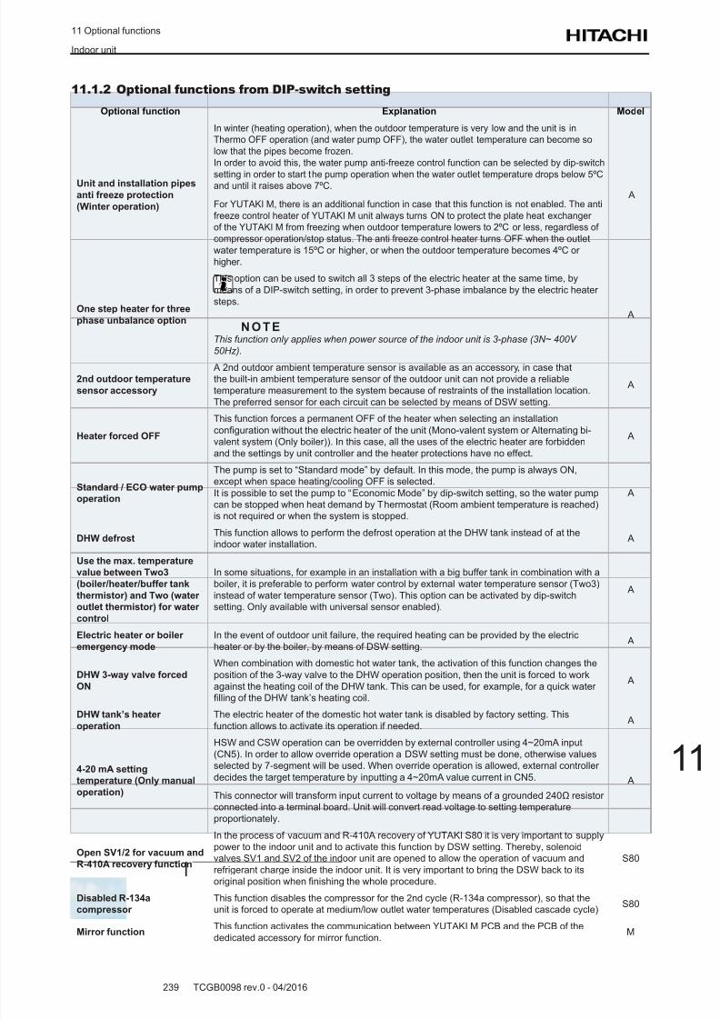
8/16/2019 Hitachi Yutaki Series 2016 Αντλίες θερμότητας
http://slidepdf.com/reader/full/hitachi-yutaki-series-2016- 249/256
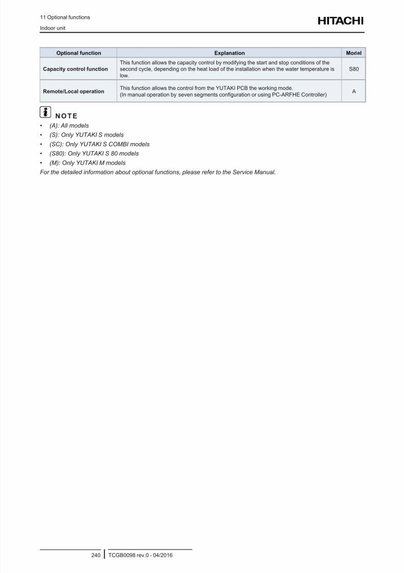
8/16/2019 Hitachi Yutaki Series 2016 Αντλίες θερμότητας
http://slidepdf.com/reader/full/hitachi-yutaki-series-2016- 250/256
11 Optional functions
Indoor unit
TCGB0098 rev.0 - 04/2016240
Optional function Explanation Model
Capacity control function
This function allows the capacity control by modifying the start and stop conditions of the
second cycle, depending on the heat load of the installation when the water temperature is
low.
S80
Remote/Local operationThis function allows the control from the YUTAKI PCB the working mode.
(In manual operation by seven segments conguration or using PC-ARFHE Controller) A
N O T E
• (A): All models
• (S): Only YUTAKI S models
• (SC): Only YUTAKI S COMBI models
• (S80): Only YUTAKI S 80 models
• (M): Only YUTAKI M models
For the detailed information about optional functions, please refer to the Service Manual.
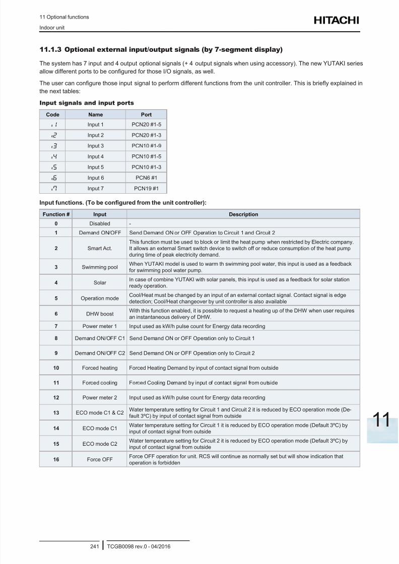
8/16/2019 Hitachi Yutaki Series 2016 Αντλίες θερμότητας
http://slidepdf.com/reader/full/hitachi-yutaki-series-2016- 251/256
11 Optional functions
Indoor unit
TCGB0098 rev.0 - 04/2016241
11
11.1.3 Optional external input/output signals (by 7-segment display)
The system has 7 input and 4 output optional signals (+ 4 output signals when using accessory). The new YUTAKI series
allow different ports to be congured for those I/O signals, as well.
The user can congure those input signal to perform different functions from the unit controller. This is briey explained in
the next tables:
Input signals and input ports
Code Name Port
i1 Input 1 PCN20 #1-5
i2 Input 2 PCN20 #1-3
i3 Input 3 PCN10 #1-9
i4 Input 4 PCN10 #1-5
i5 Input 5 PCN10 #1-3
i6 Input 6 PCN6 #1
i7 Input 7 PCN19 #1
Input functions. (To be congured from the unit controller):
Function # Input Description
0 Disabled -
1 Demand ON/OFF Send Demand ON or OFF Operation to Circuit 1 and Circuit 2
2 Smart Act.
This function must be used to block or limit the heat pump when restricted by Electric company.It allows an external Smart switch device to switch off or reduce consumption of the heat pump
during time of peak electricity demand.
3 Swimming poolWhen YUTAKI model is used to warm th swimming pool water, this input is used as a feedback
for swimming pool water pump.
4 Solar In case of combine YUTAKI with solar panels, this input is used as a feedback for solar station
ready operation.
5 Operation mode Cool/Heat must be changed by an input of an external contact signal. Contact signal is edgedetection; Cool/Heat changeover by unit controller is also available
6 DHW boostWith this function enabled, it is possible to request a heating up of the DHW when user requires
an instantaneous delivery of DHW.
7 Power meter 1 Input used as kW/h pulse count for Energy data recording
8 Demand ON/OFF C1 Send Demand ON or OFF Operation only to Circuit 1
9 Demand ON/OFF C2 Send Demand ON or OFF Operation only to Circuit 2
10 Forced heating Forced Heating Demand by input of contact signal from outside
11 Forced cooling Forced Cooling Demand by input of contact signal from outside
12 Power meter 2 Input used as kW/h pulse count for Energy data recording
13 ECO mode C1 & C2Water temperature setting for Circuit 1 and Circuit 2 it is reduced by ECO operation mode (De-
fault 3ºC) by input of contact signal from outside
14 ECO mode C1Water temperature setting for Circuit 1 it is reduced by ECO operation mode (Default 3ºC) byinput of contact signal from outside
15 ECO mode C2Water temperature setting for Circuit 2 it is reduced by ECO operation mode (Default 3ºC) byinput of contact signal from outside
16 Force OFFForce OFF operation for unit. RCS will continue as normally set but will show indication that
operation is forbidden
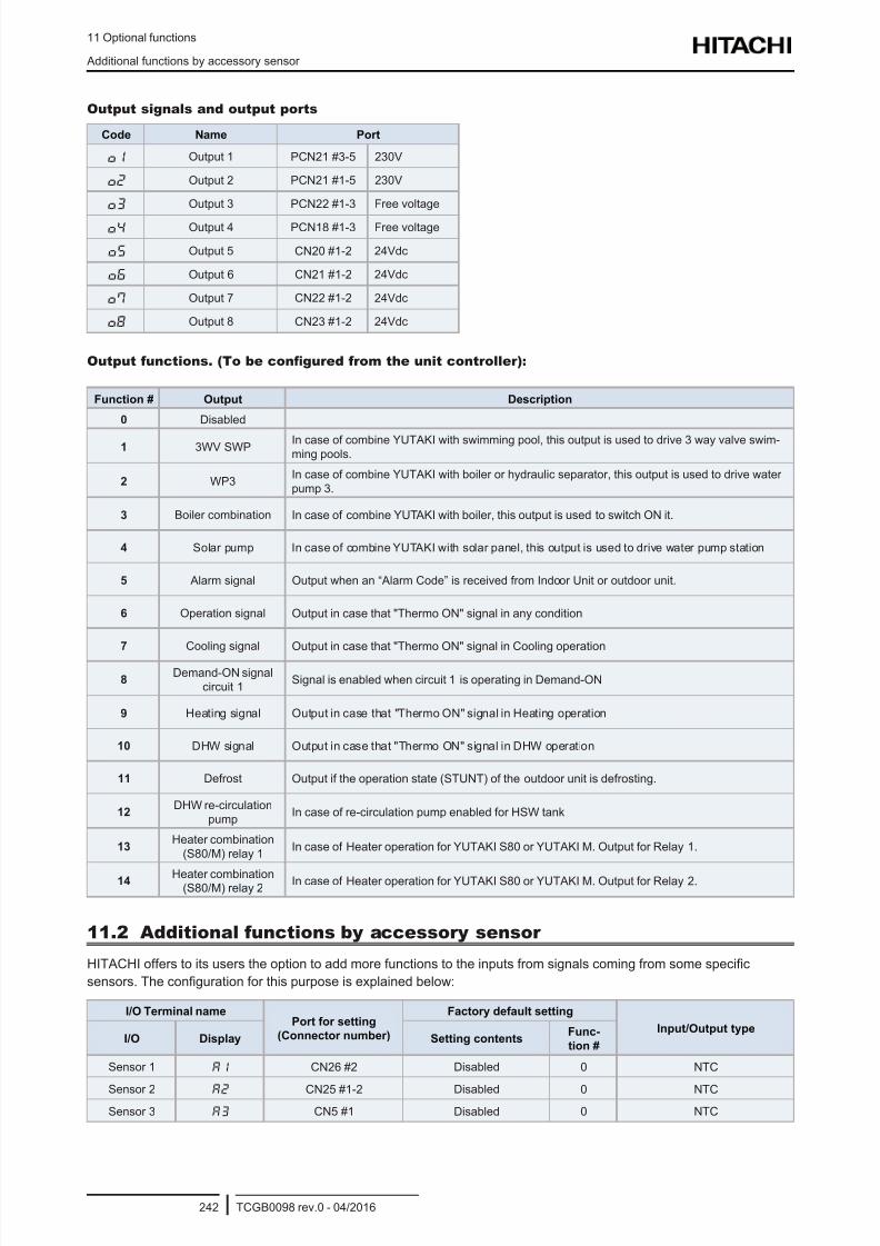
8/16/2019 Hitachi Yutaki Series 2016 Αντλίες θερμότητας
http://slidepdf.com/reader/full/hitachi-yutaki-series-2016- 252/256
11 Optional functions
Additional functions by accessory sensor
TCGB0098 rev.0 - 04/2016242
Output signals and output ports
Code Name Port
o1 Output 1 PCN21 #3-5 230V
o2 Output 2 PCN21 #1-5 230V
o3 Output 3 PCN22 #1-3 Free voltage
o4 Output 4 PCN18 #1-3 Free voltage
o5 Output 5 CN20 #1-2 24Vdc
o6 Output 6 CN21 #1-2 24Vdc
o7 Output 7 CN22 #1-2 24Vdc
o8 Output 8 CN23 #1-2 24Vdc
Output functions. (To be congured from the unit controller):
Function # Output Description
0 Disabled
1 3WV SWPIn case of combine YUTAKI with swimming pool, this output is used to drive 3 way valve swim-ming pools.
2 WP3In case of combine YUTAKI with boiler or hydraulic separator, this output is used to drive water
pump 3.
3 Boiler combination In case of combine YUTAKI with boiler, this output is used to switch ON it.
4 Solar pump In case of combine YUTAKI with solar panel, this output is used to drive water pump station
5 Alarm signal Output when an “Alarm Code” is received from Indoor Unit or outdoor unit.
6 Operation signal Output in case that "Thermo ON" signal in any condition
7 Cooling signal Output in case that "Thermo ON" signal in Cooling operation
8Demand-ON signal
circuit 1Signal is enabled when circuit 1 is operating in Demand-ON
9 Heating signal Output in case that "Thermo ON" signal in Heating operation
10 DHW signal Output in case that "Thermo ON" signal in DHW operation
11 Defrost Output if the operation state (STUNT) of the outdoor unit is defrosting.
12DHW re-circulation
pumpIn case of re-circulation pump enabled for HSW tank
13Heater combination
(S80/M) relay 1In case of Heater operation for YUTAKI S80 or YUTAKI M. Output for Relay 1.
14 Heater combination(S80/M) relay 2
In case of Heater operation for YUTAKI S80 or YUTAKI M. Output for Relay 2.
11.2 Additional functions by accessory sensor
HITACHI offers to its users the option to add more functions to the inputs from signals coming from some specic
sensors. The conguration for this purpose is explained below:
I/O Terminal namePort for setting
(Connector number)
Factory default setting
Input/Output typeI/O Display Setting contents
Func-
tion #
Sensor 1 A1 CN26 #2 Disabled 0 NTC
Sensor 2 A2 CN25 #1-2 Disabled 0 NTC
Sensor 3 A3 CN5 #1 Disabled 0 NTC
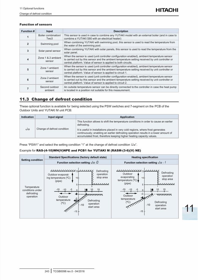
8/16/2019 Hitachi Yutaki Series 2016 Αντλίες θερμότητας
http://slidepdf.com/reader/full/hitachi-yutaki-series-2016- 253/256
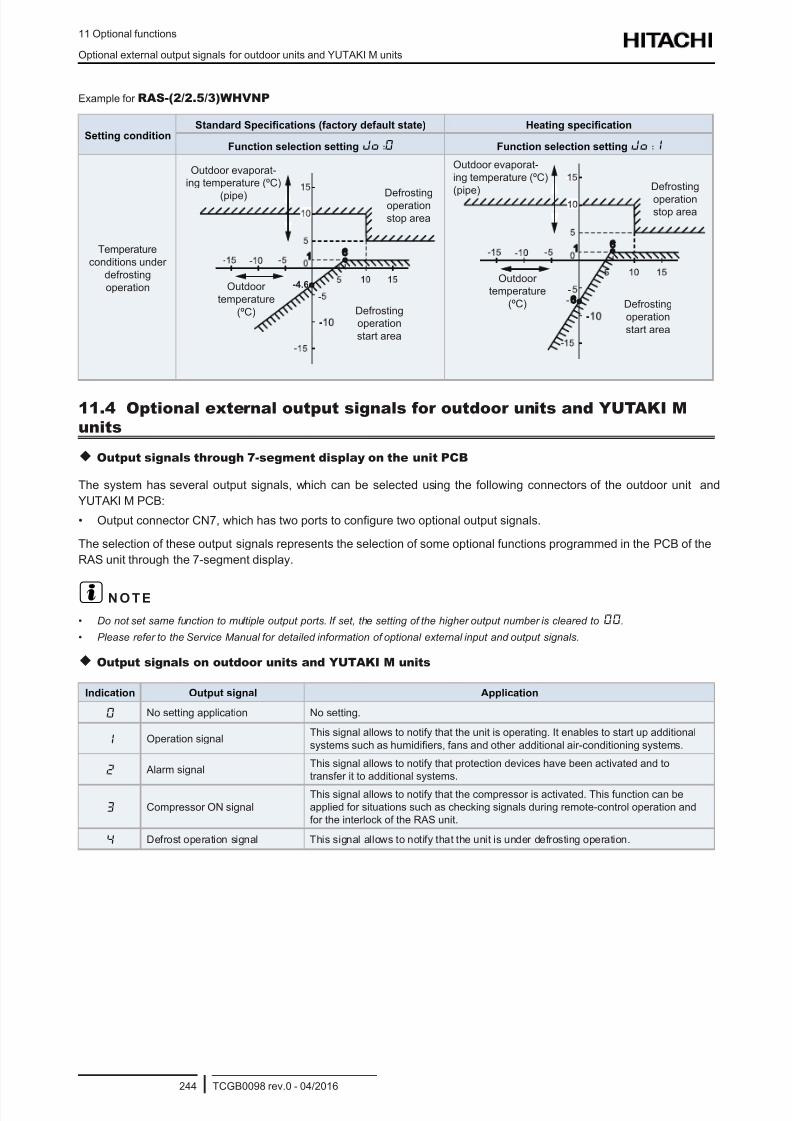
8/16/2019 Hitachi Yutaki Series 2016 Αντλίες θερμότητας
http://slidepdf.com/reader/full/hitachi-yutaki-series-2016- 254/256
11 Optional functions
Optional external output signals for outdoor units and YUTAKI M units
TCGB0098 rev.0 - 04/2016244
Example for RAS-(2/2.5/3)WHVNP
Setting conditionStandard Specications (factory default state) Heating specication
Function selection setting Jo:0 Function selection setting Jo:1
Temperature
conditions under
defrosting
operation -4.6
Defrosting
operation
start area
Defrostingoperation
stop area
Outdoor
temperature
(ºC)
Outdoor evaporat-
ing temperature (ºC)
(pipe)
Outdoor evaporat-
ing temperature (ºC)
(pipe) Defrosting
operationstop area
Defrosting
operation
start area
Outdoor
temperature
(ºC)
11.4 Optional external output signals for outdoor units and YUTAKI M
units
Output signals through 7-segment display on the unit PCB
The system has several output signals, which can be selected using the following connectors of the outdoor unit and
YUTAKI M PCB:
• Output connector CN7, which has two ports to congure two optional output signals.
The selection of these output signals represents the selection of some optional functions programmed in the PCB of the
RAS unit through the 7-segment display.
? N O T E
• Do not set same function to multiple output ports. If set, the setting of the higher output number is cleared to00.
• Please refer to the Service Manual for detailed information of optional external input and output signals.
Output signals on outdoor units and YUTAKI M units
Indication Output signal Application
0 No setting application No setting.
1 Operation signalThis signal allows to notify that the unit is operating. It enables to start up additional
systems such as humidiers, fans and other additional air-conditioning systems.
2 Alarm signalThis signal allows to notify that protection devices have been activated and to
transfer it to additional systems.
3 Compressor ON signal
This signal allows to notify that the compressor is activated. This function can be
applied for situations such as checking signals during remote-control operation and
for the interlock of the RAS unit.
4 Defrost operation signal This signal allows to notify that the unit is under defrosting operation.

8/16/2019 Hitachi Yutaki Series 2016 Αντλίες θερμότητας
http://slidepdf.com/reader/full/hitachi-yutaki-series-2016- 255/256

8/16/2019 Hitachi Yutaki Series 2016 Αντλίες θερμότητας
http://slidepdf.com/reader/full/hitachi-yutaki-series-2016- 256/256