High rate, fast timing Glass RPC for the high CMS muon ... · Prepared for submission to JINST...
14
Prepared for submission to JINST XIII th Workshop on Resistive Plate Chambers and related detectors 22-26 February, 2016 Ghent University, Belgium High rate, fast timing Glass RPC for the high η CMS muon detectors F. Lagarde, M. Gouzevitch, I. Laktineh, V. Buridon, X. Chen, C. Combaret, A. Eynard, L. Germani, G. Grenier, H. Mathez, L. Mirabito, A. Petrukhin, A. Steen, W. Tromeur aa Y. Wang, A. Gong ab , N. Moreau, C. de la Taille, F. Dulucq ac , A. Cimmino, S. Crucy, A.Fagot, M. Gul, A.A.O. Rios, M. Tytgat, N. Zaganidis b , S. Aly, Y. Assran, A. Radi, A. Sayed c , G. Singh d , M. Abbrescia, G. Iaselli, M. Maggi, G. Pugliese, P. Verwilligen e , W. Van Doninck f , S. Colafranceschi, A. Sharma g , L. Benussi, S. Bianco, D.Piccolo, F. Primavera h , V. Bhatnagar, R. Kumari, A. Mehta, J. Singh i , A. Ahmad, W. Ahmed, H., M. I. Asghar, I. M. Awan, R. Hoorani, S. Muhammad, H. Shahzad, M.A. Shah j , S. W. Cho, S. Y. Choi, B. Hong, M. H. Kang, K. S. Lee, J. H. Lim, S. K. Park k , M.S. Kim l , S. Carpinteyro Bernardino, I. Pedraza, C. Uribe Estrada m , S. Carrillo Moreno, F. Vazquez Valencia n , L.M. Pant o , S. Buontempo, N. Cavallo, M. Esposito, F. Fabozzi, G. Lanza, I. Orso, L. Lista, S. Meola, M. Merola, P. Paolucci, F. Thyssen p , A. Braghieri, A. Magnani, P. Montagna, C. Riccardi, P. Salvini, I. Vai, P. Vitulo q , Y. Ban, S.J. Qian r , M. Choi s , Y. Choi, J. Goh, D. Kim t , A. Aleksandrov, R. Hadjiiska, P. Iaydjiev, M. Rodozov, S. Stoykova, G. Sultanov, M. Vutova u , A. Dimitrov, L. Litov, B. Pavlov, P. Petkov v , I. Bagaturia, D. Lomidze w , C. Avila, A. Cabrera, J.C. Sanabria x , I. Crotty y , J. Vaitkus z on behalf of CMS RPC collaboration aa Institut de Physique Nucleaire de Lyon, Universite de Lyon, Universite Claude Bernard Lyon 1, CNRS-IN2P3, Villeurbanne, France ab Tsinghua University, Beijing, China ac Omega-École Polytechnique, Paris, France b Ghent university, Dept. of Physics and Astronomy, Proeftuinstraat 86, B-9000 Ghent, Belgium c Egyptian Network for High Energy Physics, Academy of Scientific Research and Technology, 101 Kasr El-Einy St. Cairo Egypt. d Chulalongkorn University, Department of Physics, Faculty of Science, Payathai Road, Phatumwan, Bangkok, THAILAND - 10330. e INFN, Sezione di Bari, Via Orabona 4, IT-70126 Bari, Italy. f Vrije Universiteit Brussel, Boulevard de la Plaine 2, 1050 Ixelles, Belgium. g Physics Department CERN, CH-1211 Geneva 23, Switzerland. h INFN, Laboratori Nazionali di Frascati (LNF), Via Enrico Fermi 40, IT-00044 Frascati, Italy. i Department of Physics, Panjab University, Chandigarh Mandir 160 014, India. arXiv:1606.01398v2 [physics.ins-det] 22 Jul 2016
Transcript of High rate, fast timing Glass RPC for the high CMS muon ... · Prepared for submission to JINST...
Prepared for submission to JINST
XIIIth Workshop on Resistive Plate Chambers and related detectors22-26 February, 2016Ghent University, Belgium
High rate, fast timing Glass RPC for the high η
CMS muon detectors
F. Lagarde, M. Gouzevitch, I. Laktineh, V. Buridon, X. Chen, C. Combaret, A. Eynard,L. Germani, G. Grenier, H.Mathez, L.Mirabito, A. Petrukhin, A. Steen, W. Tromeuraa
Y. Wang, A. Gongab , N. Moreau, C. de la Taille, F. Dulucqac , A. Cimmino, S. Crucy,A.Fagot, M. Gul, A.A.O. Rios, M. Tytgat, N. Zaganidisb , S. Aly, Y. Assran, A. Radi,A. Sayedc , G. Singhd , M. Abbrescia, G. Iaselli, M. Maggi, G. Pugliese, P.Verwilligene , W. Van Doninckf , S. Colafranceschi, A. Sharmag , L. Benussi, S.Bianco, D.Piccolo, F. Primaverah , V. Bhatnagar, R. Kumari, A. Mehta, J. Singhi ,A. Ahmad, W. Ahmed, H., M. I. Asghar, I. M. Awan, R. Hoorani, S. Muhammad, H.Shahzad, M.A. Shahj , S. W. Cho, S. Y. Choi, B. Hong, M. H. Kang, K. S. Lee, J.H. Lim, S. K. Parkk , M.S. Kiml , S. Carpinteyro Bernardino, I. Pedraza, C. UribeEstradam , S. Carrillo Moreno, F. Vazquez Valencian , L.M. Panto , S. Buontempo,N. Cavallo, M. Esposito, F. Fabozzi, G. Lanza, I. Orso, L. Lista, S. Meola, M.Merola, P. Paolucci, F. Thyssenp , A. Braghieri, A. Magnani, P. Montagna, C.Riccardi, P. Salvini, I. Vai, P. Vituloq , Y. Ban, S.J. Qianr , M. Chois , Y. Choi, J.Goh, D. Kimt , A. Aleksandrov, R. Hadjiiska, P. Iaydjiev, M. Rodozov, S. Stoykova,G. Sultanov, M. Vutovau , A. Dimitrov, L. Litov, B. Pavlov, P. Petkovv , I. Bagaturia,D. Lomidzew , C. Avila, A. Cabrera, J.C. Sanabriax , I. Crottyy , J. Vaitkusz
on behalf of CMS RPC collaborationaaInstitut de Physique Nucleaire de Lyon, Universite de Lyon, Universite Claude Bernard Lyon 1,CNRS-IN2P3, Villeurbanne, France
abTsinghua University, Beijing, ChinaacOmega-École Polytechnique, Paris, FrancebGhent university, Dept. of Physics and Astronomy, Proeftuinstraat 86, B-9000 Ghent, BelgiumcEgyptian Network for High Energy Physics, Academy of Scientific Research and Technology, 101Kasr El-Einy St. Cairo Egypt.
dChulalongkorn University, Department of Physics, Faculty of Science, Payathai Road, Phatumwan,Bangkok, THAILAND - 10330.
eINFN, Sezione di Bari, Via Orabona 4, IT-70126 Bari, Italy.fVrije Universiteit Brussel, Boulevard de la Plaine 2, 1050 Ixelles, Belgium.gPhysics Department CERN, CH-1211 Geneva 23, Switzerland.hINFN, Laboratori Nazionali di Frascati (LNF), Via Enrico Fermi 40, IT-00044 Frascati, Italy.iDepartment of Physics, Panjab University, Chandigarh Mandir 160 014, India.
arX
iv:1
606.
0139
8v2
[ph
ysic
s.in
s-de
t] 2
2 Ju
l 201
6
jNational Centre for Physics, Quaid-i-Azam University, Islamabad, Pakistan.kKorea University, Department of Physics, 145 Anam-ro, Seongbuk-gu, Seoul 02841, Republic ofKorea.lKyungpook National University, 80 Daehak-ro, Buk-gu, Daegu 41566, Republic of Korea.
mBenemerita Universidad Autonoma de Puebla, Puebla, Mexico.nUniversidad Iberoamericana, Mexico City, Mexico.oNuclear Physics Division Bhabha Atomic Research Centre Mumbai 400 085, INDIA.pINFN, Sezione di Napoli, Complesso Univ. Monte S. Angelo, Via Cintia, IT-80126 Napoli, Italy.qINFN, Sezione di Pavia, Via Bassi 6, IT-Pavia, Italy.rSchool of Physics, Peking University, Beijing 100871, China.sUniversity of Seoul, 163 Seoulsiripdae-ro, Dongdaemun-gu, Seoul, Republic of Korea.tSungkyunkwan University, 2066 Seobu-ro, Jangan-gu, Suwon-si, Gyeonggi-do, Republic of Korea.uBulgarian Academy of Sciences, Inst. for Nucl. Res. and Nucl. Energy, Tzarigradsko shausseeBoulevard 72, BG-1784 Sofia, Bulgaria.
vFaculty of Physics, University of Sofia,5, James Bourchier Boulevard, BG-1164 Sofia, Bulgaria.wTbilisi University, 1 Ilia Chavchavadze Ave, Tbilisi 0179, Georgia.xUniversidad de Los Andes, Apartado Aereo 4976, Carrera 1E, no. 18A 10, CO-Bogota, Colombia.yDept. of Physics, Wisconsin University, Madison, WI 53706, United States.zVilnius University, Vilnius, Lithuania.
E-mail: [email protected], [email protected], [email protected]
Abstract: The HL-LHC phase is designed to increase by an order of magnitude the amountof data to be collected by the LHC experiments. To achieve this goal in a reasonable timescale the instantaneous luminosity would also increase by an order of magnitude up to6 · 1034 cm−2s−1. The region of the forward muon spectrometer (|η| > 1.6) is not equippedwith RPC stations. The increase of the expected particles rate up to 2 kHz/cm2 ( includinga safety factor 3 ) motivates the installation of RPC chambers to guarantee redundancywith the CSC chambers already present. The current CMS RPC technology cannot sustainthe expected background level. The new technology that will be chosen should have ahigh rate capability and provide a good spatial and timing resolution. A new generation ofGlass-RPC (GRPC) using low-resistivity glass is proposed to equip at least the two most faraway of the four high η muon stations of CMS. First the design of small size prototypes andstudies of their performance in high-rate particles flux are presented. Then the proposeddesigns for large size chambers and their fast-timing electronic readout are examined andpreliminary results are provided.
Keywords: Gaseous detectors; Resistive-plate chambers; Particle tracking detectors (Gaseousdetectors); Front-end electronics for detector readout; Materials for gaseous detectors
ArXiv ePrint: 1606.01398
Contents
1 Introduction 1
2 Small GRPC chambers 32.1 GRPC structure 32.2 Small GRPC performance in test beams 32.3 Small GRPC performance in GIF++ 6
3 Large GRPC chambers 8
4 Fast timing electronics 10
5 Conclusion and next steps 10
1 Introduction
In the present CMS detector, all the muon stations are equipped with two kinds of muondetectors. Drift Tubes (DT) and Resistive Plate Chambers (RPC) detectors are used toensure a good redundancy in the barrel region. In the endcap region, Cathode Strip Cham-bers (CSC) and RPC are used except in the stations of high eta region (η > 1.6) whereonly CSC detectors are present. To guarantee a redundancy in this region and improvethe muon trigger efficiency it is planned to add new chambers during long shut-downs LS2and LS3. The projected increase of the LHC luminosity up to 6 · 1034 cm−2s−1 during theHL-LHC phase suggests that new detectors with high rate capability are needed [1].
Figure 1 summarizes the muon spectrometer upgrade project. Gaseous electron multi-plier (GEM) detectors are proposed to equip the two first (GE1/1 & GE2/1) of these fourhigh η muon stations. These high rate detectors provide the spatial resolution needed tosolve the ambiguity that could affect the CSC when several particles are present. For theother stations (RE3/1 & RE4/1), several RPC technologies are proposed. In this regionthe expected rate during HL-LHC program estimated with FLUKA [2][3] shall not exceed2 kHz/cm2 including a safety factor 3 [1]. Glass RPC is one of the proposed detectors.
In its simple version a generic RPC detector is made of two resistive plates whose outerface is covered by a resistive coating. The two plates play the role of the electrodes. Thedistance between the two electrodes is maintained constant using spacers. A gas mixturecirculates in between the two plates. Applying high voltage (HV) on the two electrodescreates an electric field inside the gas gap. When a charged particle crosses the detector,it ionizes the gas molecules. Primary electron-ion pairs are produced and an avalanche isinitiated under the electric field. After the passage of the charged particle, the avalanchecharges are absorbed through the resistive electrodes. The higher the resistivity of theelectrodes the longer the time needed to evacuate the charge.
– 1 –
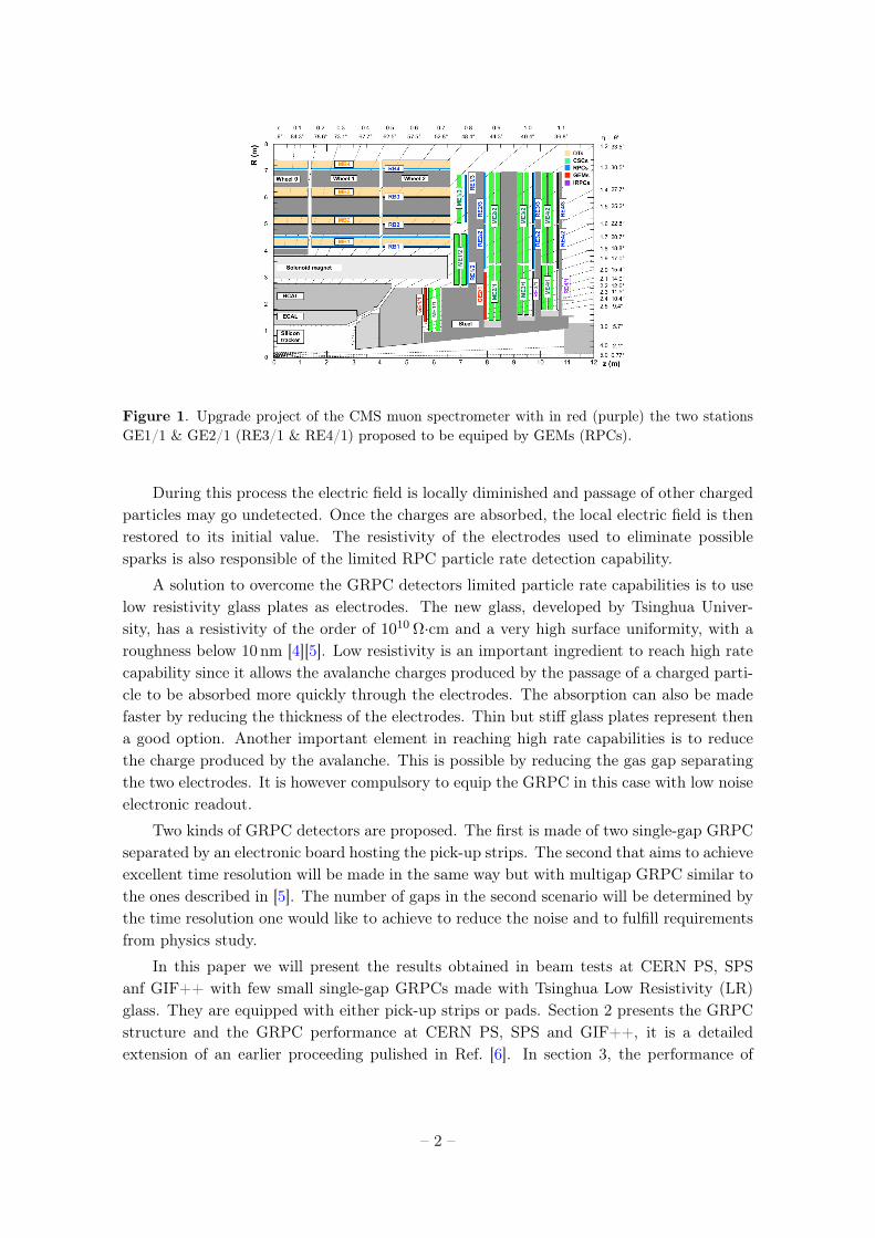
Figure 1. Upgrade project of the CMS muon spectrometer with in red (purple) the two stationsGE1/1 & GE2/1 (RE3/1 & RE4/1) proposed to be equiped by GEMs (RPCs).
During this process the electric field is locally diminished and passage of other chargedparticles may go undetected. Once the charges are absorbed, the local electric field is thenrestored to its initial value. The resistivity of the electrodes used to eliminate possiblesparks is also responsible of the limited RPC particle rate detection capability.
A solution to overcome the GRPC detectors limited particle rate capabilities is to uselow resistivity glass plates as electrodes. The new glass, developed by Tsinghua Univer-sity, has a resistivity of the order of 1010 Ω·cm and a very high surface uniformity, with aroughness below 10 nm [4][5]. Low resistivity is an important ingredient to reach high ratecapability since it allows the avalanche charges produced by the passage of a charged parti-cle to be absorbed more quickly through the electrodes. The absorption can also be madefaster by reducing the thickness of the electrodes. Thin but stiff glass plates represent thena good option. Another important element in reaching high rate capabilities is to reducethe charge produced by the avalanche. This is possible by reducing the gas gap separatingthe two electrodes. It is however compulsory to equip the GRPC in this case with low noiseelectronic readout.
Two kinds of GRPC detectors are proposed. The first is made of two single-gap GRPCseparated by an electronic board hosting the pick-up strips. The second that aims to achieveexcellent time resolution will be made in the same way but with multigap GRPC similar tothe ones described in [5]. The number of gaps in the second scenario will be determined bythe time resolution one would like to achieve to reduce the noise and to fulfill requirementsfrom physics study.
In this paper we will present the results obtained in beam tests at CERN PS, SPSanf GIF++ with few small single-gap GRPCs made with Tsinghua Low Resistivity (LR)glass. They are equipped with either pick-up strips or pads. Section 2 presents the GRPCstructure and the GRPC performance at CERN PS, SPS and GIF++, it is a detailedextension of an earlier proceeding pulished in Ref. [6]. In section 3, the performance of
– 2 –
large two single-gap GRPC detectors are studied with cosmic rays. Finally, section 4,gives a short description of the electronic readout proposed to achieve high precision timeresolution as well as the preliminary results obtained with such system.
2 Small GRPC chambers
2.1 GRPC structure
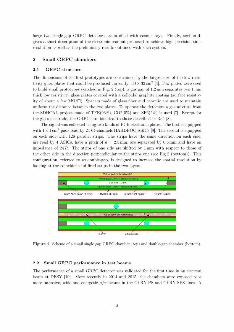
The dimensions of the first prototypes are constrained by the largest size of the low resis-tivity glass plates that could be produced currently: 30× 32 cm2 [4]. Few plates were usedto build small prototypes sketched in Fig. 2 (top): a gas gap of 1.2mm separates two 1mmthick low resistivity glass plates covered with a colloidal graphite coating (surface resistiv-ity of about a few MΩ/). Spacers made of glass fiber and ceramic are used to maintainuniform the distance between the two plates. To operate the detectors a gas mixture fromthe SDHCAL project made of TFE(93%), CO2(5%) and SF6(2%) is used [7]. Except forthe glass electrode, the GRPCs are identical to those described in Ref. [8].
The signal was collected using two kinds of PCB electronic plates. The first is equippedwith 1× 1 cm2 pads read by 24 64-channels HARDROC ASICs [9]. The second is equippedon each side with 128 parallel strips. The strips have the same direction on each side,are read by 4 ASICs, have a pitch of d = 2.5mm, are separated by 0.5mm and have animpedance of 24Ω. The strips of one side are shifted by 1mm with respect to those ofthe other side in the direction perpendicular to the strips one (see Fig.2 (bottom)). Thisconfiguration, referred to as double-gap, is designed to increase the spatial resolution bylooking at the coincidence of fired strips in the two layers.
Anode glass (1mm) + resistive coating
Cathode glass (1mm) + resistive coating
Ceramic ball spacerGlass ber frame (1.2mm)
Glas gap (1.2mm)
Mylar® (175 m)
PCB support (polycarbonate)
Mylar® (50 m)
2.5mm strip0.5mm
PCB support (polycarbonate)
Figure 2. Scheme of a small single gap GRPC chamber (top) and double-gap chamber (bottom).
2.2 Small GRPC performance in test beams
The performance of a small GRPC detector was validated for the first time in an electronbeam at DESY [10]. More recently in 2014 and 2015, the chambers were exposed to amore intensive, wide and energetic µ/π beams in the CERN-PS and CERN-SPS lines. A
– 3 –
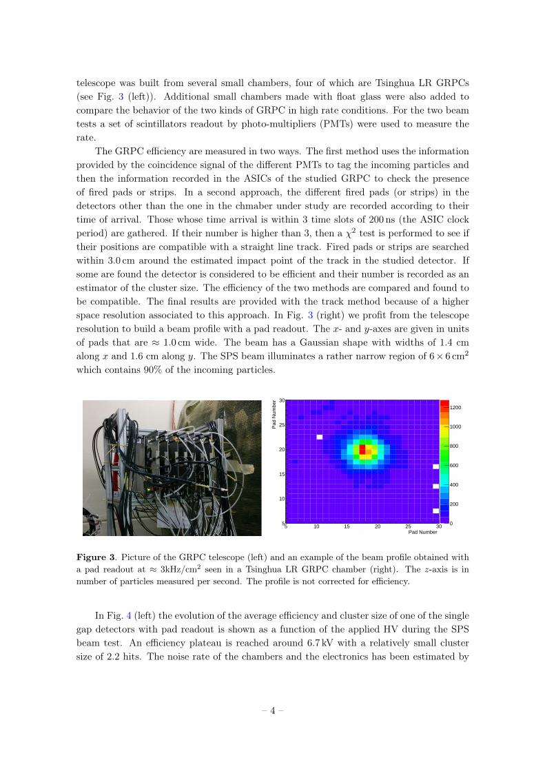
telescope was built from several small chambers, four of which are Tsinghua LR GRPCs(see Fig. 3 (left)). Additional small chambers made with float glass were also added tocompare the behavior of the two kinds of GRPC in high rate conditions. For the two beamtests a set of scintillators readout by photo-multipliers (PMTs) were used to measure therate.
The GRPC efficiency are measured in two ways. The first method uses the informationprovided by the coincidence signal of the different PMTs to tag the incoming particles andthen the information recorded in the ASICs of the studied GRPC to check the presenceof fired pads or strips. In a second approach, the different fired pads (or strips) in thedetectors other than the one in the chmaber under study are recorded according to theirtime of arrival. Those whose time arrival is within 3 time slots of 200 ns (the ASIC clockperiod) are gathered. If their number is higher than 3, then a χ2 test is performed to see iftheir positions are compatible with a straight line track. Fired pads or strips are searchedwithin 3.0 cm around the estimated impact point of the track in the studied detector. Ifsome are found the detector is considered to be efficient and their number is recorded as anestimator of the cluster size. The efficiency of the two methods are compared and found tobe compatible. The final results are provided with the track method because of a higherspace resolution associated to this approach. In Fig. 3 (right) we profit from the telescoperesolution to build a beam profile with a pad readout. The x- and y-axes are given in unitsof pads that are ≈ 1.0 cm wide. The beam has a Gaussian shape with widths of 1.4 cmalong x and 1.6 cm along y. The SPS beam illuminates a rather narrow region of 6× 6 cm2
which contains 90% of the incoming particles.
Pad Number 5 10 15 20 25 30
Pad
Num
ber
5
10
15
20
25
30
Flux_Events1Entries 53324Mean x 17.51Mean y 19.43RMS x 4.474RMS y 4.525
0
200
400
600
800
1000
1200
Flux_Events1Entries 53324Mean x 17.51Mean y 19.43RMS x 4.474RMS y 4.525
Figure 3. Picture of the GRPC telescope (left) and an example of the beam profile obtained witha pad readout at ≈ 3kHz/cm2 seen in a Tsinghua LR GRPC chamber (right). The z-axis is innumber of particles measured per second. The profile is not corrected for efficiency.
In Fig. 4 (left) the evolution of the average efficiency and cluster size of one of the singlegap detectors with pad readout is shown as a function of the applied HV during the SPSbeam test. An efficiency plateau is reached around 6.7 kV with a relatively small clustersize of 2.2 hits. The noise rate of the chambers and the electronics has been estimated by
– 4 –
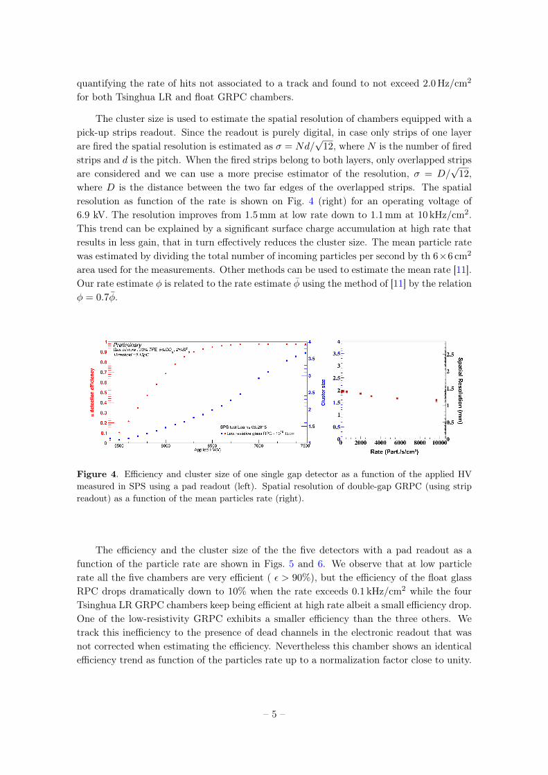
quantifying the rate of hits not associated to a track and found to not exceed 2.0 Hz/cm2
for both Tsinghua LR and float GRPC chambers.
The cluster size is used to estimate the spatial resolution of chambers equipped with apick-up strips readout. Since the readout is purely digital, in case only strips of one layerare fired the spatial resolution is estimated as σ = Nd/
√12, where N is the number of fired
strips and d is the pitch. When the fired strips belong to both layers, only overlapped stripsare considered and we can use a more precise estimator of the resolution, σ = D/
√12,
where D is the distance between the two far edges of the overlapped strips. The spatialresolution as function of the rate is shown on Fig. 4 (right) for an operating voltage of6.9 kV. The resolution improves from 1.5mm at low rate down to 1.1mm at 10 kHz/cm2.This trend can be explained by a significant surface charge accumulation at high rate thatresults in less gain, that in turn effectively reduces the cluster size. The mean particle ratewas estimated by dividing the total number of incoming particles per second by th 6×6 cm2
area used for the measurements. Other methods can be used to estimate the mean rate [11].Our rate estimate φ is related to the rate estimate φ using the method of [11] by the relationφ = 0.7φ.
Figure 4. Efficiency and cluster size of one single gap detector as a function of the applied HVmeasured in SPS using a pad readout (left). Spatial resolution of double-gap GRPC (using stripreadout) as a function of the mean particles rate (right).
The efficiency and the cluster size of the the five detectors with a pad readout as afunction of the particle rate are shown in Figs. 5 and 6. We observe that at low particlerate all the five chambers are very efficient ( ε > 90%), but the efficiency of the float glassRPC drops dramatically down to 10% when the rate exceeds 0.1 kHz/cm2 while the fourTsinghua LR GRPC chambers keep being efficient at high rate albeit a small efficiency drop.One of the low-resistivity GRPC exhibits a smaller efficiency than the three others. Wetrack this inefficiency to the presence of dead channels in the electronic readout that wasnot corrected when estimating the efficiency. Nevertheless this chamber shows an identicalefficiency trend as function of the particles rate up to a normalization factor close to unity.
– 5 –
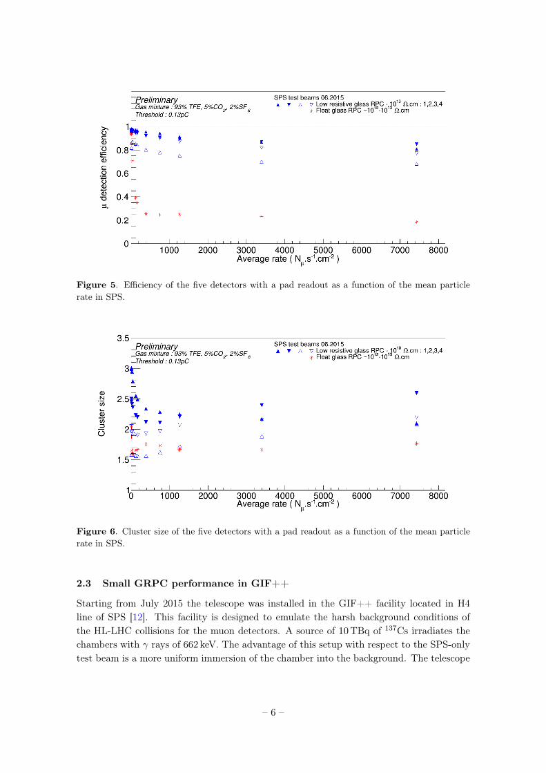
Figure 5. Efficiency of the five detectors with a pad readout as a function of the mean particlerate in SPS.
Figure 6. Cluster size of the five detectors with a pad readout as a function of the mean particlerate in SPS.
2.3 Small GRPC performance in GIF++
Starting from July 2015 the telescope was installed in the GIF++ facility located in H4line of SPS [12]. This facility is designed to emulate the harsh background conditions ofthe HL-LHC collisions for the muon detectors. A source of 10TBq of 137Cs irradiates thechambers with γ rays of 662 keV. The advantage of this setup with respect to the SPS-onlytest beam is a more uniform immersion of the chamber into the background. The telescope
– 6 –
is irradiated during long periods (many months) to collect a large cumulated charge.In between those periods a muon beam of several thousands of µ / spill is used to test
the efficiency of the chambers and monitor the aging process. The source is supplied witha system of movable lead attenuators that allows a reduction of the rate by factors between1 and 10−5 in several steps, in particular during the test beam periods.
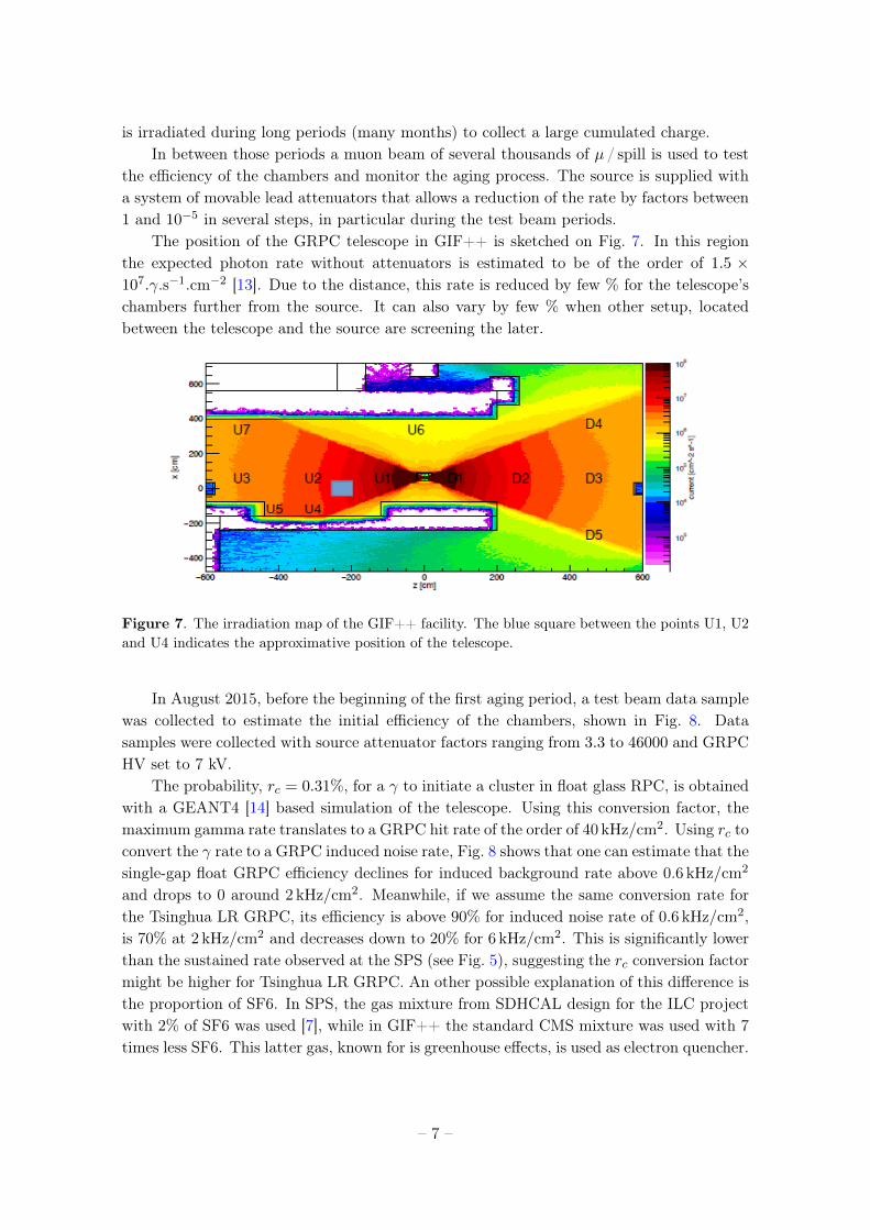
The position of the GRPC telescope in GIF++ is sketched on Fig. 7. In this regionthe expected photon rate without attenuators is estimated to be of the order of 1.5 ×10⁷.γ.s−1.cm−2 [13]. Due to the distance, this rate is reduced by few % for the telescope’schambers further from the source. It can also vary by few % when other setup, locatedbetween the telescope and the source are screening the later.
Figure 7. The irradiation map of the GIF++ facility. The blue square between the points U1, U2and U4 indicates the approximative position of the telescope.
In August 2015, before the beginning of the first aging period, a test beam data samplewas collected to estimate the initial efficiency of the chambers, shown in Fig. 8. Datasamples were collected with source attenuator factors ranging from 3.3 to 46000 and GRPCHV set to 7 kV.
The probability, rc = 0.31%, for a γ to initiate a cluster in float glass RPC, is obtainedwith a GEANT4 [14] based simulation of the telescope. Using this conversion factor, themaximum gamma rate translates to a GRPC hit rate of the order of 40 kHz/cm2. Using rc toconvert the γ rate to a GRPC induced noise rate, Fig. 8 shows that one can estimate that thesingle-gap float GRPC efficiency declines for induced background rate above 0.6 kHz/cm2
and drops to 0 around 2 kHz/cm2. Meanwhile, if we assume the same conversion rate forthe Tsinghua LR GRPC, its efficiency is above 90% for induced noise rate of 0.6 kHz/cm2,is 70% at 2 kHz/cm2 and decreases down to 20% for 6 kHz/cm2. This is significantly lowerthan the sustained rate observed at the SPS (see Fig. 5), suggesting the rc conversion factormight be higher for Tsinghua LR GRPC. An other possible explanation of this difference isthe proportion of SF6. In SPS, the gas mixture from SDHCAL design for the ILC projectwith 2% of SF6 was used [7], while in GIF++ the standard CMS mixture was used with 7times less SF6. This latter gas, known for is greenhouse effects, is used as electron quencher.
– 7 –
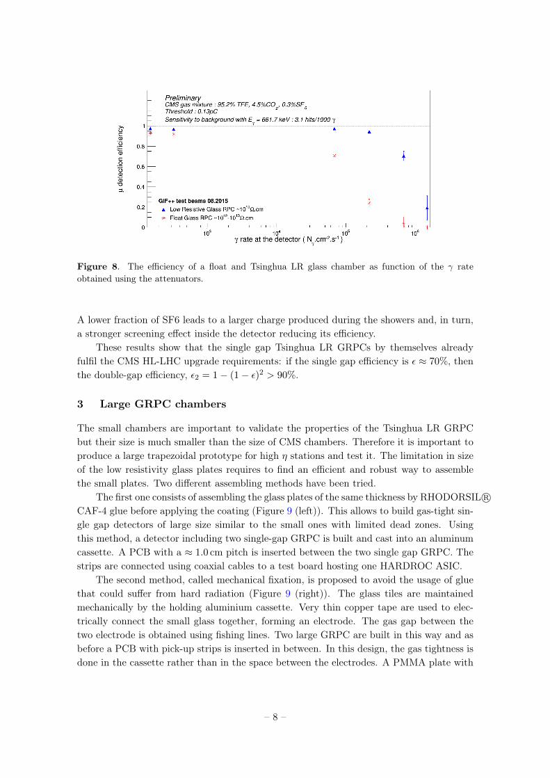
Figure 8. The efficiency of a float and Tsinghua LR glass chamber as function of the γ rateobtained using the attenuators.
A lower fraction of SF6 leads to a larger charge produced during the showers and, in turn,a stronger screening effect inside the detector reducing its efficiency.
These results show that the single gap Tsinghua LR GRPCs by themselves alreadyfulfil the CMS HL-LHC upgrade requirements: if the single gap efficiency is ε ≈ 70%, thenthe double-gap efficiency, ε2 = 1− (1− ε)2 > 90%.
3 Large GRPC chambers
The small chambers are important to validate the properties of the Tsinghua LR GRPCbut their size is much smaller than the size of CMS chambers. Therefore it is important toproduce a large trapezoidal prototype for high η stations and test it. The limitation in sizeof the low resistivity glass plates requires to find an efficient and robust way to assemblethe small plates. Two different assembling methods have been tried.
The first one consists of assembling the glass plates of the same thickness by RHODORSIL R©CAF-4 glue before applying the coating (Figure 9 (left)). This allows to build gas-tight sin-gle gap detectors of large size similar to the small ones with limited dead zones. Usingthis method, a detector including two single-gap GRPC is built and cast into an aluminumcassette. A PCB with a ≈ 1.0 cm pitch is inserted between the two single gap GRPC. Thestrips are connected using coaxial cables to a test board hosting one HARDROC ASIC.
The second method, called mechanical fixation, is proposed to avoid the usage of gluethat could suffer from hard radiation (Figure 9 (right)). The glass tiles are maintainedmechanically by the holding aluminium cassette. Very thin copper tape are used to elec-trically connect the small glass together, forming an electrode. The gas gap between thetwo electrode is obtained using fishing lines. Two large GRPC are built in this way and asbefore a PCB with pick-up strips is inserted in between. In this design, the gas tightness isdone in the cassette rather than in the space between the electrodes. A PMMA plate with
– 8 –
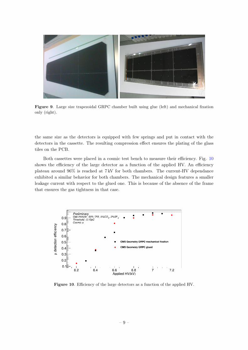
Figure 9. Large size trapezoidal GRPC chamber built using glue (left) and mechanical fixationonly (right).
the same size as the detectors is equipped with few springs and put in contact with thedetectors in the cassette. The resulting compression effect ensures the plating of the glasstiles on the PCB.
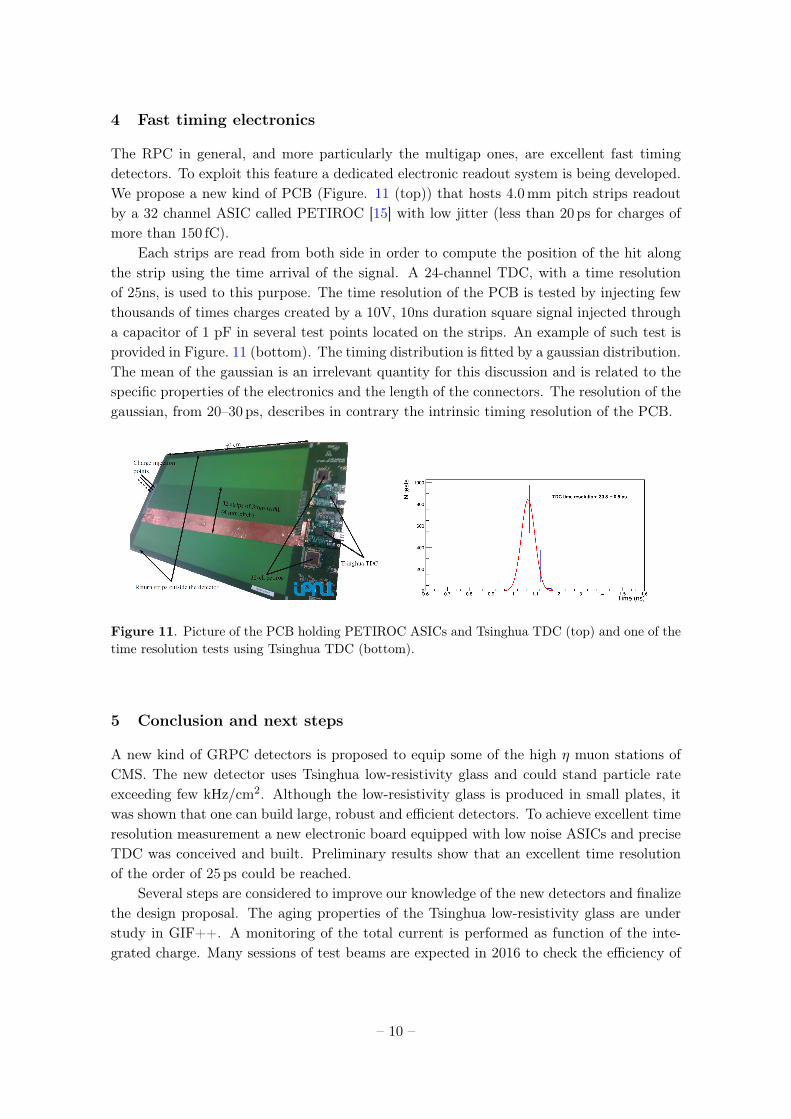
Both cassettes were placed in a cosmic test bench to measure their efficiency. Fig. 10shows the efficiency of the large detector as a function of the applied HV. An efficiencyplateau around 96% is reached at 7 kV for both chambers. The current-HV dependanceexhibited a similar behavior for both chambers. The mechanical design features a smallerleakage current with respect to the glued one. This is because of the absence of the framethat ensures the gas tightness in that case.
Figure 10. Efficiency of the large detectors as a function of the applied HV.
– 9 –
4 Fast timing electronics
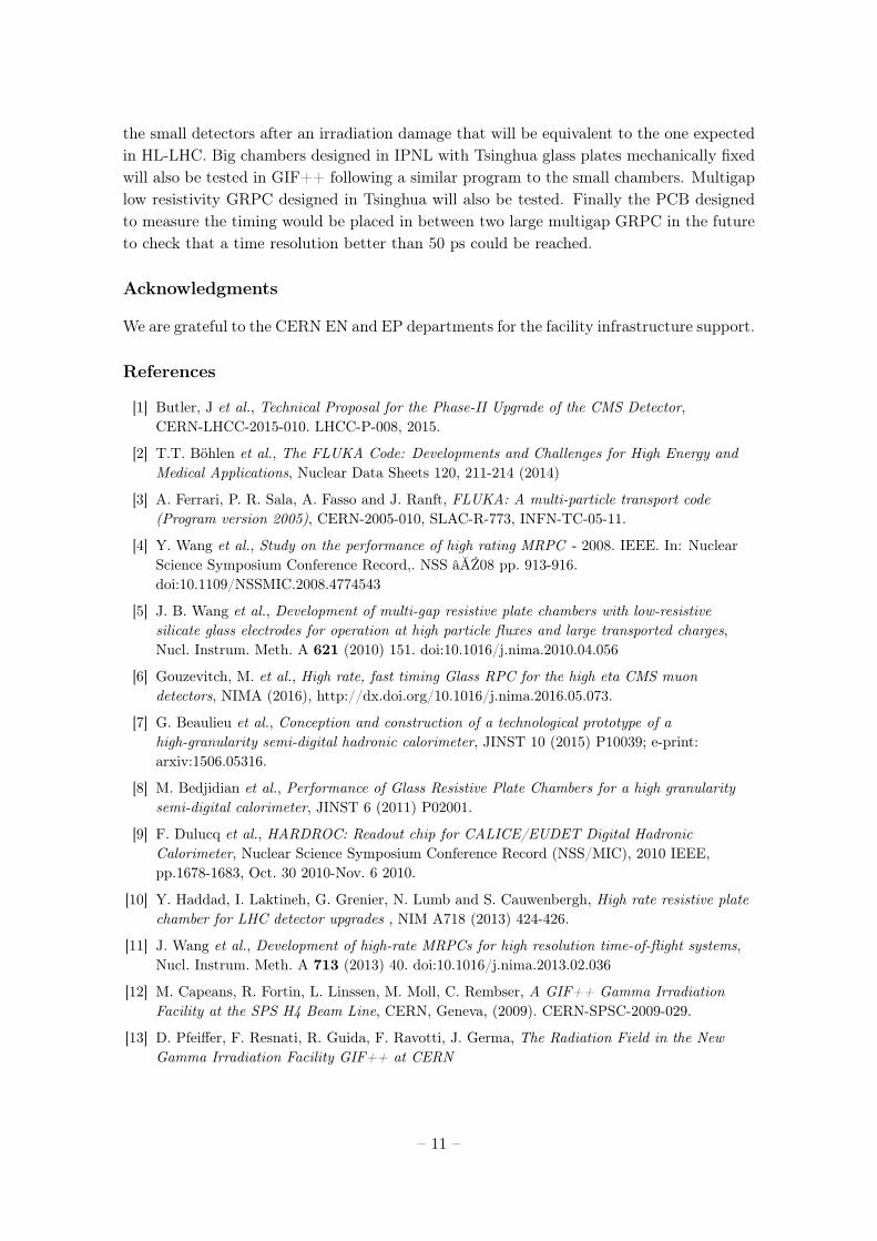
The RPC in general, and more particularly the multigap ones, are excellent fast timingdetectors. To exploit this feature a dedicated electronic readout system is being developed.We propose a new kind of PCB (Figure. 11 (top)) that hosts 4.0mm pitch strips readoutby a 32 channel ASIC called PETIROC [15] with low jitter (less than 20 ps for charges ofmore than 150 fC).
Each strips are read from both side in order to compute the position of the hit alongthe strip using the time arrival of the signal. A 24-channel TDC, with a time resolutionof 25ns, is used to this purpose. The time resolution of the PCB is tested by injecting fewthousands of times charges created by a 10V, 10ns duration square signal injected througha capacitor of 1 pF in several test points located on the strips. An example of such test isprovided in Figure. 11 (bottom). The timing distribution is fitted by a gaussian distribution.The mean of the gaussian is an irrelevant quantity for this discussion and is related to thespecific properties of the electronics and the length of the connectors. The resolution of thegaussian, from 20–30 ps, describes in contrary the intrinsic timing resolution of the PCB.
Figure 11. Picture of the PCB holding PETIROC ASICs and Tsinghua TDC (top) and one of thetime resolution tests using Tsinghua TDC (bottom).
5 Conclusion and next steps
A new kind of GRPC detectors is proposed to equip some of the high η muon stations ofCMS. The new detector uses Tsinghua low-resistivity glass and could stand particle rateexceeding few kHz/cm2. Although the low-resistivity glass is produced in small plates, itwas shown that one can build large, robust and efficient detectors. To achieve excellent timeresolution measurement a new electronic board equipped with low noise ASICs and preciseTDC was conceived and built. Preliminary results show that an excellent time resolutionof the order of 25 ps could be reached.
Several steps are considered to improve our knowledge of the new detectors and finalizethe design proposal. The aging properties of the Tsinghua low-resistivity glass are understudy in GIF++. A monitoring of the total current is performed as function of the inte-grated charge. Many sessions of test beams are expected in 2016 to check the efficiency of
– 10 –
the small detectors after an irradiation damage that will be equivalent to the one expectedin HL-LHC. Big chambers designed in IPNL with Tsinghua glass plates mechanically fixedwill also be tested in GIF++ following a similar program to the small chambers. Multigaplow resistivity GRPC designed in Tsinghua will also be tested. Finally the PCB designedto measure the timing would be placed in between two large multigap GRPC in the futureto check that a time resolution better than 50 ps could be reached.
Acknowledgments
We are grateful to the CERN EN and EP departments for the facility infrastructure support.
References
[1] Butler, J et al., Technical Proposal for the Phase-II Upgrade of the CMS Detector,CERN-LHCC-2015-010. LHCC-P-008, 2015.
[2] T.T. Böhlen et al., The FLUKA Code: Developments and Challenges for High Energy andMedical Applications, Nuclear Data Sheets 120, 211-214 (2014)
[3] A. Ferrari, P. R. Sala, A. Fasso and J. Ranft, FLUKA: A multi-particle transport code(Program version 2005), CERN-2005-010, SLAC-R-773, INFN-TC-05-11.
[4] Y. Wang et al., Study on the performance of high rating MRPC - 2008. IEEE. In: NuclearScience Symposium Conference Record,. NSS âĂŹ08 pp. 913-916.doi:10.1109/NSSMIC.2008.4774543
[5] J. B. Wang et al., Development of multi-gap resistive plate chambers with low-resistivesilicate glass electrodes for operation at high particle fluxes and large transported charges,Nucl. Instrum. Meth. A 621 (2010) 151. doi:10.1016/j.nima.2010.04.056
[6] Gouzevitch, M. et al., High rate, fast timing Glass RPC for the high eta CMS muondetectors, NIMA (2016), http://dx.doi.org/10.1016/j.nima.2016.05.073.
[7] G. Beaulieu et al., Conception and construction of a technological prototype of ahigh-granularity semi-digital hadronic calorimeter, JINST 10 (2015) P10039; e-print:arxiv:1506.05316.
[8] M. Bedjidian et al., Performance of Glass Resistive Plate Chambers for a high granularitysemi-digital calorimeter, JINST 6 (2011) P02001.
[9] F. Dulucq et al., HARDROC: Readout chip for CALICE/EUDET Digital HadronicCalorimeter, Nuclear Science Symposium Conference Record (NSS/MIC), 2010 IEEE,pp.1678-1683, Oct. 30 2010-Nov. 6 2010.
[10] Y. Haddad, I. Laktineh, G. Grenier, N. Lumb and S. Cauwenbergh, High rate resistive platechamber for LHC detector upgrades , NIM A718 (2013) 424-426.
[11] J. Wang et al., Development of high-rate MRPCs for high resolution time-of-flight systems,Nucl. Instrum. Meth. A 713 (2013) 40. doi:10.1016/j.nima.2013.02.036
[12] M. Capeans, R. Fortin, L. Linssen, M. Moll, C. Rembser, A GIF++ Gamma IrradiationFacility at the SPS H4 Beam Line, CERN, Geneva, (2009). CERN-SPSC-2009-029.
[13] D. Pfeiffer, F. Resnati, R. Guida, F. Ravotti, J. Germa, The Radiation Field in the NewGamma Irradiation Facility GIF++ at CERN
– 11 –
[14] S. Agostinelli et al., Geant4 a simulation toolkit, NIM A506 (2003) 250-303.
[15] J. Fleury et al., Petiroc, a new front-end ASIC for time of flight application, 2013 IEEENuclear Science Symposium and Medical Imaging Conference (2013 NSS/MIC).
– 12 –


![Optimization of the beam crossing angle at the ILC for · arXiv:1801.10471v2 [physics.acc-ph] 27 Feb 2018 Prepared for submission to JINST Optimization of the beam crossing angle](https://static.fdocument.org/doc/165x107/5b14d1857f8b9a54488c4489/optimization-of-the-beam-crossing-angle-at-the-ilc-for-arxiv180110471v2-.jpg)