MFSE45High Precision and High Efficiency High Rake Cutter
8
MFSE45 High Precision and High Efficiency High Rake Cutter Roughing Condition (fz = 0.25 mm/t) Provides Excellent Surface Finish (0.8 μmRa or Less) * Maintains Long Tool Life with High-Precision Inserts Newly Developed Chipbreakers for Steel, Stainless Steel, and Aluminum Improved Productivity with Excellent Chip Control Rough and Finish in 1 Pass with Excellent Surface Finish *Based on internal evaluation with wiper insert installed. MFSE45 High Precision and High Efficiency High Rake Cutter NEW SUS304 0.46μmRa
Transcript of MFSE45High Precision and High Efficiency High Rake Cutter
MFSE45High Precision and High Efficiency
High Rake Cutter
Roughing Condition (fz = 0.25 mm/t) Provides Excellent Surface Finish (0.8 μmRa or Less) *
Maintains Long Tool Life with High-Precision Inserts
Newly Developed Chipbreakers for Steel, Stainless Steel, and Aluminum
Improved Productivity with Excellent Chip Control
Rough and Finish in 1 Pass with Excellent Surface Finish
*Based on internal evaluation with wiper insert installed.
MFSE45High Precision and High Efficiency High Rake Cutter
NEW
SUS304 0.46μmRa
1
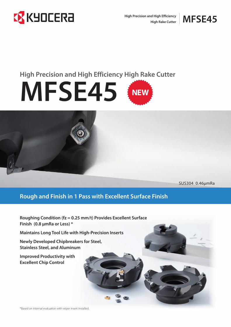
Delivers high-quality surfaces by roughing and finishing simultaneously
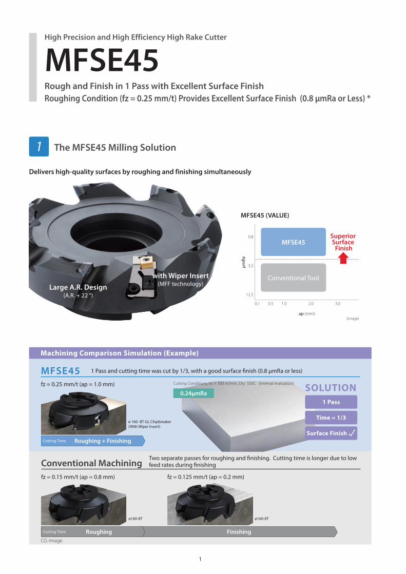
Machining Comparison Simulation (Example)
Conventional Machining
Finishing
Two separate passes for roughing and fi nishing. Cutting time is longer due to low feed rates during fi nishing
fz = 0.15 mm/t (ap = 0.8 mm) fz = 0.125 mm/t (ap = 0.2 mm)
ø160-8T ø160-8T
0.24μmRa
MFSE45
1 Pass
Time = 1/3
Surface Finish Roughing + Finishing
1 Pass and cutting time was cut by 1/3, with a good surface fi nish (0.8 μmRa or less)
fz = 0.25 mm/t (ap = 1.0 mm)
ø 160 -8T GL Chipbreaker(With Wiper Insert)
SOLUTION
with Wiper Insert(MFF technology)Large A.R. Design
(A.R. + 22 °)
ap (mm)
2.00.5 1.00.1 3.0
3.2
12.5
0.8μm
RaMFSE45
Conventional Tool
Superior Surface
Finish
MFSE45 (VALUE)
(image)
Cutting Conditions: Vc = 300 m/min, Dry S50C (Internal evaluation)
Cutting Time
RoughingCG image
Cutting Time
High Precision and High Efficiency High Rake Cutter
MFSE45Rough and Finish in 1 Pass with Excellent Surface FinishRoughing Condition (fz = 0.25 mm/t) Provides Excellent Surface Finish (0.8 μmRa or Less) *
The MFSE45 Milling Solution1
2
Effect on surface finish(Image)
Surface roughness in stainless steel machining (Internal evaluation)
Effect on wear (User evaluation)
Front Edge Runout: Small Surface Roughness: Good
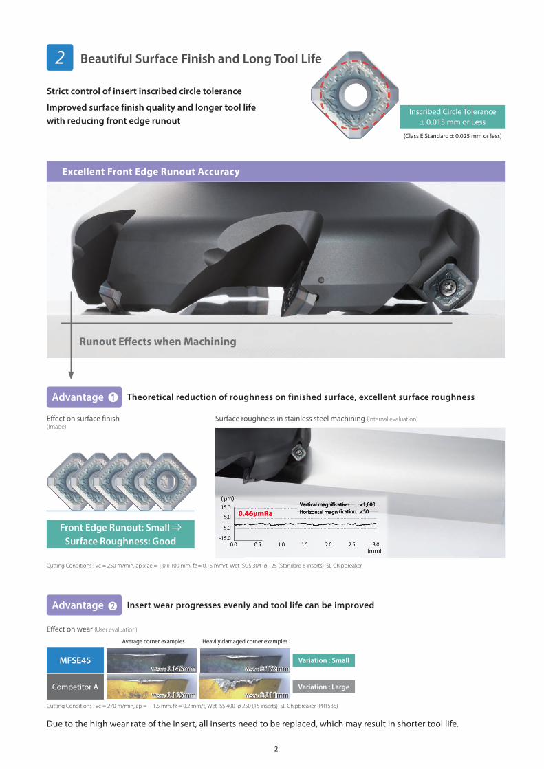
(Class E Standard ± 0.025 mm or less)
Strict control of insert inscribed circle tolerance
Improved surface finish quality and longer tool life with reducing front edge runout
Inscribed Circle Tolerance± 0.015 mm or Less
Variation : Small
Variation : Large
Advantage
Advantage
Theoretical reduction of roughness on finished surface, excellent surface roughness
Insert wear progresses evenly and tool life can be improved
Excellent Front Edge Runout Accuracy
Runout E� ects when Machining
Cutting Conditions : Vc = 250 m/min, ap x ae = 1.0 x 100 mm, fz = 0.15 mm/t, Wet SUS 304 ø 125 (Standard 6 inserts) SL Chipbreaker
Cutting Conditions : Vc = 270 m/min, ap = ~ 1.5 mm, fz = 0.2 mm/t, Wet SS 400 ø 250 (15 inserts) SL Chipbreaker (PR1535)
Average corner examples Heavily damaged corner examples
MFSE45
Competitor A
Wear : 0.145mm Wear : 0.172mm
Wear : 0.105mm Wear : 0.911mm
Due to the high wear rate of the insert, all inserts need to be replaced, which may result in shorter tool life.
0.5
0.46μmRa
0.0 1.0 1.5 2.0 2.5 3.0
-5.0
-15.0
15.0
5.0
Vertical magniVertical magniffication ication : ×1,000: ×1,000Horizontal magniHorizontal magniffication : ×50ication : ×50
(mm)
(μm)
Beautiful Surface Finish and Long Tool Life2
3
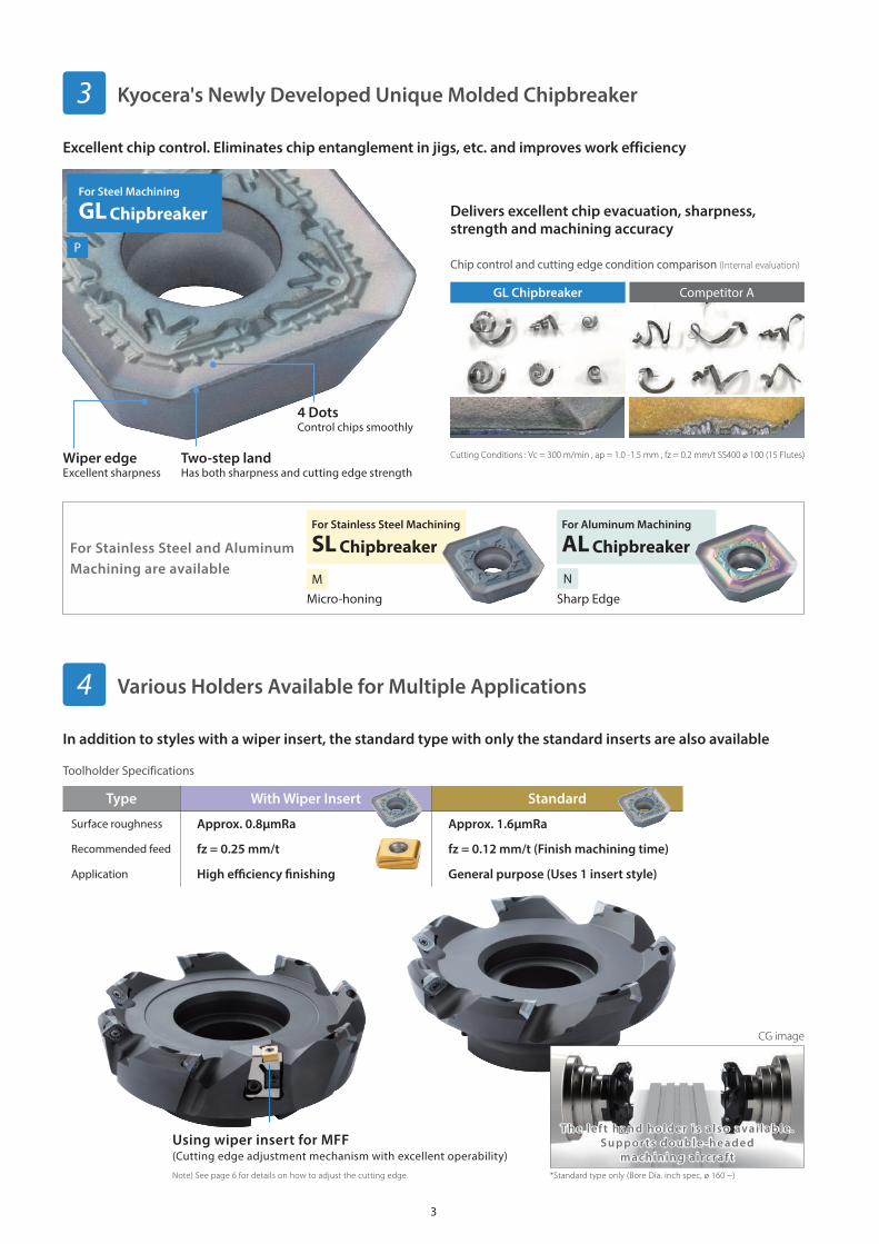
Type With Wiper Insert Standard
Surface roughness Approx. 0.8μmRa Approx. 1.6μmRa
Recommended feed fz = 0.25 mm/t fz = 0.12 mm/t (Finish machining time)
Application High effi ciency fi nishing General purpose (Uses 1 insert style)
For Steel Machining
GL Chipbreaker
For Stainless Steel Machining
SL ChipbreakerFor Aluminum Machining
AL Chipbreaker
Wiper edgeExcellent sharpness
Two-step landHas both sharpness and cutting edge strength
4 DotsControl chips smoothly
Micro-honing Sharp Edge
Chip control and cutting edge condition comparison (Internal evaluation)
Toolholder Specifications
Delivers excellent chip evacuation, sharpness, strength and machining accuracy
GL Chipbreaker Competitor A
Cutting Conditions : Vc = 300 m/min , ap = 1.0 -1.5 mm , fz = 0.2 mm/t SS400 ø 100 (15 Flutes)
For Stainless Steel and Aluminum Machining are available
The lef t hand holder is a lso avai lable.Suppor ts double -headed
machining aircraf t
M
P
N
Using wiper insert for MFF (Cutting edge adjustment mechanism with excellent operability)
Note) See page 6 for details on how to adjust the cutting edge. *Standard type only (Bore Dia. inch spec, ø 160 ~)
CG image
Excellent chip control. Eliminates chip entanglement in jigs, etc. and improves work efficiency
In addition to styles with a wiper insert, the standard type with only the standard inserts are also available
Kyocera's Newly Developed Unique Molded Chipbreaker3
Various Holders Available for Multiple Applications4
4
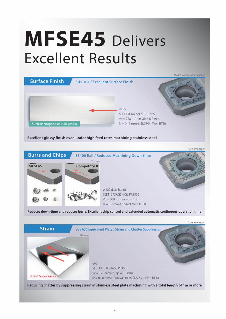
MFSE45 DeliversExcellent Results
ø125SEET13T3AGSN-SL PR1535Vc = 250 m/min, ap = 0.2 mmfz = 0.15 mm/t, SUS304 Wet BT50
Surface Finish SUS 304 / Excellent Surface Finish
Excellent glossy finish even under high feed rates machining stainless steel
ø63SEET13T3AGSN-SL PR1535Vc = 120 m/min, ap = 0.3 mmfz = 0.08 mm/t, Equivalent to SUS 630 Wet BT40
Strain SUS 630 Equivalent Plate / Strain and Chatter Suppression
Reducing chatter by suppressing strain in stainless steel plate machining with a total length of 1m or more
Strain Suppression
ø 100 (Left hand)SEET13T3AGSN-GL PR1535Vc = 300 m/min, ap = 1.5 mmfz = 0.2 mm/t, SS400 Wet BT50
Burrs and Chips SS400 Rail / Reduced Machining Down-time
Reduces down-time and reduces burrs. Excellent chip control and extended automatic continuous operation time
MFSE45 Competitor B
Surface roughness: 0.46 μm Ra
*Based on internal evaluation
*User evaluation
*User evaluation
CG image
No Burr Burr
CG image
5
Standard
With Wiper Insert
DCX
DCSFMSDCBKWW
CBDP
KDP
6LF
DC
DCCB1
DCCB2
45°
DCSFMSDCB
KWW
CBDP
KDP
6LF
DCX
DC
DCCB1
45°
DCSFMS
DCBKWW
CBDP
KDP
6LF
DCCB2
DCCB4
DCCB3
DCCB1
DCDCX
45°
DCDCX
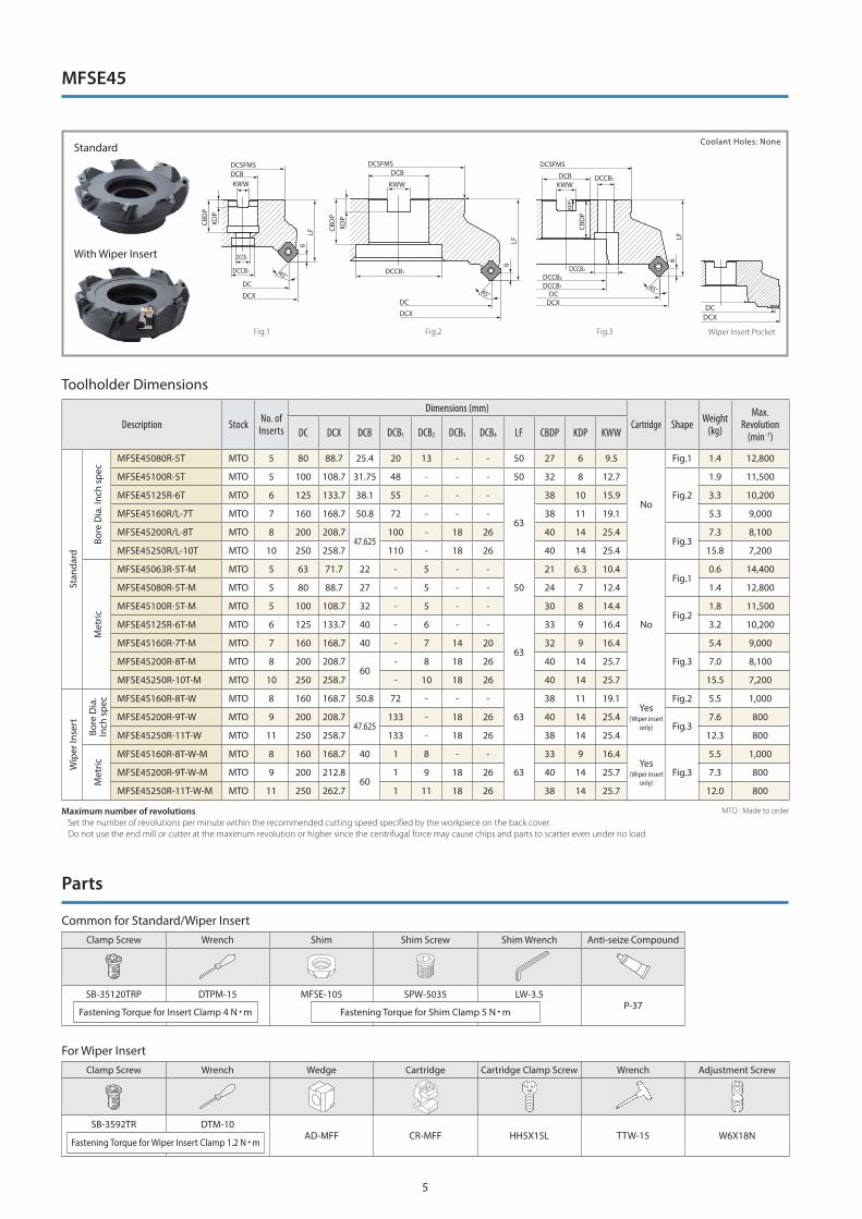
MTO : Made to orderMaximum number of revolutions Set the number of revolutions per minute within the recommended cutting speed specified by the workpiece on the back cover. Do not use the end mill or cutter at the maximum revolution or higher since the centrifugal force may cause chips and parts to scatter even under no load.
Toolholder Dimensions
For Wiper Insert
Common for Standard/Wiper Insert
Description Stock No. of Inserts
Dimensions (mm)Cartridge Shape Weight
(kg)
Max.Revolution
(min -1)DC DCX DCB DCB1 DCB2 DCB3 DCB4 LF CBDP KDP KWW
Stan
dard
Bore
Dia
. Inc
h sp
ec
MFSE45080R-5T MTO 5 80 88.7 25.4 20 13 - - 50 27 6 9.5
No
Fig.1 1.4 12,800
MFSE45100R-5T MTO 5 100 108.7 31.75 48 - - - 50 32 8 12.7
Fig.2
1.9 11,500
MFSE45125R-6T MTO 6 125 133.7 38.1 55 - - -
63
38 10 15.9 3.3 10,200
MFSE45160R/L-7T MTO 7 160 168.7 50.8 72 - - - 38 11 19.1 5.3 9,000
MFSE45200R/L-8T MTO 8 200 208.7 47.625
100 - 18 26 40 14 25.4Fig.3
7.3 8,100
MFSE45250R/L-10T MTO 10 250 258.7 110 - 18 26 40 14 25.4 15.8 7,200
Met
ric
MFSE45063R-5T-M MTO 5 63 71.7 22 - 5 - -
50
21 6.3 10.4
No
Fig.10.6 14,400
MFSE45080R-5T-M MTO 5 80 88.7 27 - 5 - - 24 7 12.4 1.4 12,800
MFSE45100R-5T-M MTO 5 100 108.7 32 - 5 - - 30 8 14.4Fig.2
1.8 11,500
MFSE45125R-6T-M MTO 6 125 133.7 40 - 6 - -
63
33 9 16.4 3.2 10,200
MFSE45160R-7T-M MTO 7 160 168.7 40 - 7 14 20 32 9 16.4
Fig.3
5.4 9,000
MFSE45200R-8T-M MTO 8 200 208.7 60
- 8 18 26 40 14 25.7 7.0 8,100
MFSE45250R-10T-M MTO 10 250 258.7 - 10 18 26 40 14 25.7 15.5 7,200
Wip
er In
sert
Bore
Dia
. In
ch s
pec MFSE45160R-8T-W MTO 8 160 168.7 50.8 72 - - -
63
38 11 19.1Yes
(Wiper insert only)
Fig.2 5.5 1,000
MFSE45200R-9T-W MTO 9 200 208.7 47.625
133 - 18 26 40 14 25.4Fig.3
7.6 800
MFSE45250R-11T-W MTO 11 250 258.7 133 - 18 26 38 14 25.4 12.3 800
Met
ric
MFSE45160R-8T-W-M MTO 8 160 168.7 40 1 8 - -
63
33 9 16.4Yes
(Wiper insert only)
Fig.3
5.5 1,000
MFSE45200R-9T-W-M MTO 9 200 212.8 60
1 9 18 26 40 14 25.7 7.3 800
MFSE45250R-11T-W-M MTO 11 250 262.7 1 11 18 26 38 14 25.7 12.0 800
Parts
Clamp Screw Wrench Wedge Cartridge Cartridge Clamp Screw Wrench Adjustment Screw
SB-3592TR DTM-10AD-MFF CR-MFF HH5X15L TTW-15 W6X18N
Clamp Screw Wrench Shim Shim Screw Shim Wrench Anti-seize Compound
SB-35120TRP DTPM-15 MFSE-105 SPW-5035 LW-3.5P-37
Fastening Torque for Wiper Insert Clamp 1.2 N m
Fastening Torque for Insert Clamp 4 N m Fastening Torque for Shim Clamp 5 N m
Fig.1 Fig.2 Fig.3 Wiper Insert Pocket
Coolant Holes: None
MFSE45

6
About Cutting Edge Adjustment
MTO : Made to order
Wiper Insert
Shape DescriptionDimensions (mm)
MEGACOATNANO
Cermet
MEGACOATNANO
IC S D1 INSL RE PV60M PR1525
For steel and stainless steel(Low cutting force)
LNGX 120916R-TT 9.525 4.76 4.2 12.7 1.6 MTO MTO
For cast iron
LNGX 120916 9.525 4.76 4.2 12.7 1.6 MTO MTO
INSL
IC
90°S
D1
RE
90°
RE
INSL
IC
S
D1
Applicable Inserts
Usage Classifi cation PCarbon Steel /Alloy Steel
Mold Steel
: 1st Choice
: 2nd Choice
MStainless Steel (SUS 304)
Stainless Steel (SUS 403: Martensitic)
KGray Cast Iron
Nodular Cast Iron
N Non-ferrous Metal
SHeat Resistant Alloy
Titanium Alloy
Shape DescriptionDimensions (mm) Angle MEGACOAT
NANOCVD
coatingDLC
coatingIC S D1 RE BS AN AS PR1535 PR1525 CA6535 PDL025
SEET13T3AGSN-GL 13.4 3.97 4.2 1.5 2.1 20° 29°
SEET13T3AGSN-SL 13.4 3.97 4.2 1.5 2.1 20° 29°
SEET13T3AGFN-AL 13.4 3.97 4.2 1.5 2.1 20° 29°
: Standard Stock
AS
AN
D1
SBSRE
IC
45°
AN
D1
S
AS
BSRE
IC
45°
AS
AN
D1
SBSRE
IC
45°
AS
AN
D1
SBSRE
IC
45°
AN
D1
S
AS
BSRE
IC
45°
AS
AN
D1
SBSRE
IC
45°
AS
AN
D1
SBSRE
IC
45°
AN
D1
S
AS
BSRE
IC
45°
AS
AN
D1
SBSRE
IC
45°
Fig. 1 Adjustment Direction Fig. 2 Fig. 3
1. Use the supplied TTW-15 wrench to rotate the screw and easily adjust the cutting edge position.2. Thread in one direction clockwise (Fig. 1) when adjusting. If the adjustment is completed with the screw rotated counterclockwise, the screw will become loose and chatter due to backlash.
*Since the insert cutting edge of this product has an arc shape, it cannot be adjusted correctly if the measurement position is different.3. To adjust, start with the screw turned counterclockwise about two rotations (lowering the cutting edge). Tighten the screws clockwise (raising the cutting edge) until the insert with the highest edge (Fig. 2) catches 60 μm. (Fig. 3) *Use a dial gauge to measure protrusion amount.
Wiper Insert
Do not operate
T-type Wrench(TTW -15) Rough edge Wiper insert
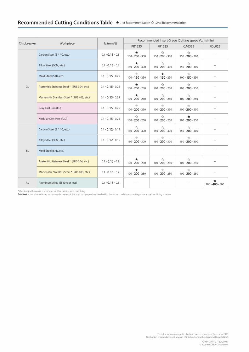
*Machining with coolant is recommended for stainless steel machining.Bold text in the table indicates recommended values. Adjust the cutting speed and feed within the above conditions according to the actual machining situation.
Recommended Cutting Conditions Table : 1st Recommendation : 2nd Recommendation
Chipbreaker Workpiece fz (mm/t)Recommended Insert Grade (Cutting speed Vc: m/min)
PR1535 PR1525 CA6535 PDL025
GL
Carbon Steel (S * * C, etc.) 0.1 - 0.15 - 0.3 150 - 200 - 300
150 - 200 - 300
150 - 200 - 300 —
Alloy Steel (SCM, etc.) 0.1 - 0.15 - 0.3 150 - 200 - 300
150 - 200 - 300
150 - 200 - 300 —
Mold Steel (SKD, etc.) 0.1 - 0.15 - 0.25
100 - 150 - 250 100 - 150 - 250
100 - 150 - 250 —
Austenitic Stainless Steel * (SUS 304, etc.) 0.1 - 0.15 - 0.25 100 - 200 - 250
100 - 200 - 250
100 - 200 - 250 —
Martensitic Stainless Steel * (SUS 403, etc.) 0.1 - 0.15 - 0.25 100 - 200 - 250
100 - 200 - 250
100 - 200 - 250 —
Gray Cast Iron (FC) 0.1 - 0.15 - 0.25
100 - 200 - 250
100 - 200 - 250
100 - 200 - 250 —
Nodular Cast Iron (FCD) 0.1 - 0.15 - 0.25
100 - 200 - 250
100 - 200 - 250 100 - 200 - 250 —
SL
Carbon Steel (S * * C, etc.) 0.1 - 0.12 - 0.15
150 - 200 - 300
150 - 200 - 300
150 - 200 - 300 —
Alloy Steel (SCM, etc.) 0.1 - 0.12 - 0.15
150 - 200 - 300
150 - 200 - 300
150 - 200 - 300 —
Mold Steel (SKD, etc.) — — — — —
Austenitic Stainless Steel * (SUS 304, etc.) 0.1 - 0.15 - 0.2 100 - 200 - 250
100 - 200 - 250
100 - 200 - 250 —
Martensitic Stainless Steel * (SUS 403, etc.) 0.1 - 0.15 - 0.2 100 - 200 - 250
100 - 200 - 250
100 - 200 - 250 —
AL Aluminum Alloy (Si 13% or less) 0.1 - 0.15 - 0.3 — — — 200 - 400 - 500
CP464 CAT/12.7T2012DNN© 2020 KYOCERA Corporation
The information contained in this brochure is current as of December 2020.Duplication or reproduction of any part of this brochure without approval is prohibited.