Gasification & Combustion - Sollabsfera.sollab.eu/downloads/Schools/Solar_Gasification_of...9 Qsolar...
19
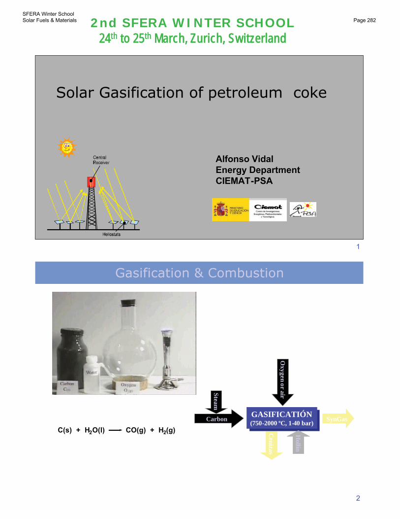
1 2nd SFERA WINTER SCHOOL 24 th to 25 th March, Zurich, Switzerland Solar Gasification of petroleum coke Alfonso Vidal Alfonso Vidal Energy Department Energy Department CIEMAT CIEMAT - - PSA PSA 2 C(s) + H 2 O(l) CO(g) + H 2 (g) Gasification & Combustion GASIFICATIÓN (750-2000 ºC, 1-40 bar) GASIFICATIÓN (750-2000 ºC, 1-40 bar) Carbon Hollín Cenizas SynGas Steam Oxygen or air SFERA Winter School Solar Fuels & Materials Page 282
Transcript of Gasification & Combustion - Sollabsfera.sollab.eu/downloads/Schools/Solar_Gasification_of...9 Qsolar...
1
2nd SFERA WINTER SCHOOL24th to 25th March, Zurich, Switzerland
Solar Gasification of petroleum coke
Alfonso VidalAlfonso VidalEnergy DepartmentEnergy DepartmentCIEMATCIEMAT--PSAPSA
2
C(s) + H2O(l) CO(g) + H2(g)
Gasification & Combustion
GASIFICATIÓN(750-2000 ºC, 1-40 bar)
GASIFICATIÓN(750-2000 ºC, 1-40 bar)
Carbon
Hollín
Cenizas
SynGas
Steam
Oxygen
orair
SFERA Winter School Solar Fuels & Materials Page 282
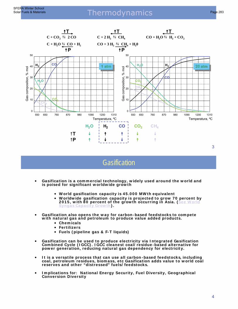
3
0
10
20
30
40
50
550 650 760 870 980 1090 1200 1310
Temperatura, ºC
Gas
com
po
sitio
n, %
mo
l
0
10
20
30
40
50
550 650 760 870 980 1090 1200 1310
Temperatura, ºC
Gas
com
po
sitio
n, %
mo
lH2 CO
CH4
CO2
H2O
H2O H2
COCO2
CH4
TP
H2O H2 CO CO2 CH4
1 atm11 atmatm 20 atm2020 atmatm
C + CO2 2 CO
C + H2O CO + H2
C + 2 H2 CH4 CO + H2O H2 + CO2
CO + 3 H2 CH4 + H20
T
P
T T
P
Thermodynamics
4
• Gasification is a commercial technology, widely used around the world and is poised for significant worldwide growth
• World gasification capacity is 45.000 MWth equivalent• Worldwide gasification capacity is projected to grow 70 percent by
2015, with 80 percent of the growth occurring in Asia. (See WorldSyngas Capacity Growth).
• Gasification also opens the way for carbon-based feedstocks to compete with natural gas and petroleum to produce value added products.
• Chemicals• Fertilizers• Fuels (pipeline gas & F-T liquids)
• Gasification can be used to produce electricity via Integrated GasificationCombined Cycle (IGCC). IGCC cleanest coal/residue-based alternative for power generation, reducing natural gas dependency for electricity.
• It is a versatile process that can use all carbon-based feedstocks, including coal, petroleum residues, biomass, etc Gasification adds value to world coal reserves and other “distressed” fuels/feedstocks.
• Implications for: National Energy Security, Fuel Diversity, GeographicalConversion Diversity
Gasification
SFERA Winter School Solar Fuels & Materials Page 283
5
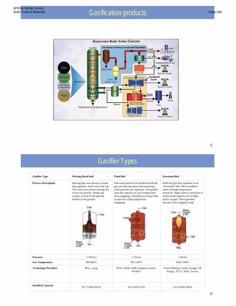
Gasification products
6
Gasifier Types
25.4 GWth (56%)0.9 GWth (2%)18.7 GWth (42%)Installed Capactiy
ConocoPhillips, Future Energy, GE Energy, ICCT, Shell, Texaco.
HTW, KRW, KBR transport reactor, Winkler
BGL, LurgiTechnology Providers
1000-1500ºC700-1100ºC300-600ºCGas Temperature
1-40 bar1-25 bar1-100 barPressure
Solid and gas flow together in an “entrained” bed. Short residence times and high temperature operation. High carbon conversion is achieved through the use of high-purity oxygen. These gasifiersoperate in the slagging mode.
The solid particles are fluidized with the gas and then the gases and remaining solid particles are separated. The gasifiertypically operates at a low temperature (non-slagging). Attempts are being made to operate at high temperature (slagging).
Moving bed, also known as fixed bed, gasifiers, feed coal in the top. The coal moves down through the reactor by gravity. Steam and oxygen are fed in through the bottom of the gasifier.
Process Description
Entrained Bed Fluid Bed Moving (fixed bed)Gasifier Type
SFERA Winter School Solar Fuels & Materials Page 284
7
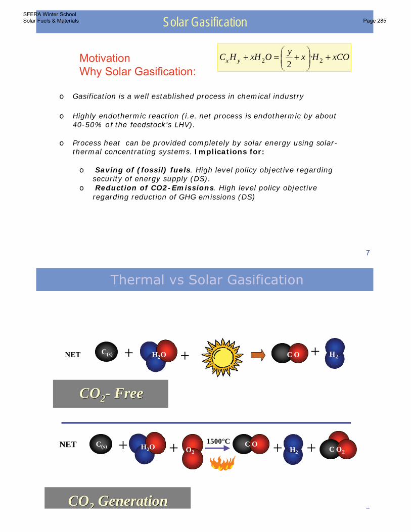
2 2·2x yy
C H xH O x H xCO
Solar Gasification
MotivationWhy Solar Gasification:
o Gasification is a well established process in chemical industry
o Highly endothermic reaction (i.e. net process is endothermic by about40-50% of the feedstock’s LHV).
o Process heat can be provided completely by solar energy using solar-thermal concentrating systems. Implications for:
o Saving of (fossil) fuels. High level policy objective regarding security of energy supply (DS).
o Reduction of CO2-Emissions. High level policy objective regarding reduction of GHG emissions (DS)
8
C(s)
H2
H2O
1500° C++ C O+
+
MECHANISM
C(s) H2O C O2
H2
++ +1500°CNET
C(s) O2 C O2+
O2
C O +
COCO22 GenerationGeneration
C(s) H2O C O H2++ +NET
COCO22-- FreeFree
Thermal vs Solar Gasification
SFERA Winter School Solar Fuels & Materials Page 285
9
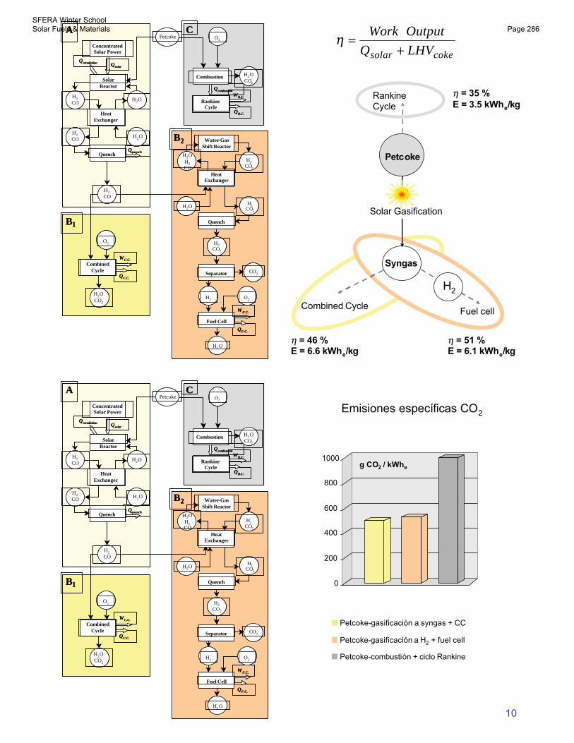
cokesolar LHVQ
OutputWork
η
η = 46 %E = 6.6 kWhe/kg
η = 35 %E = 3.5 kWhe/kg
η = 51 %E = 6.1 kWhe/kg
Syngas
Solar Gasification
Combined CycleFuel cell
RankineCycle
Petcoke
H2
QF.C.
QR.C.
Qquench
WC.C.
QC.C.
H2O
H2CO2
Water-GasShift Reactor
Qcombustion
WR.C.H2O
SolarReactor
Qreradiation
ConcentratedSolar Power
Qsolar
RankineCycle
Petcoke O2
Separator
Quench
CO2
H2
Fuel Cell
H2OCO2
HeatExchanger
H2
CO
H2OH2
CO
H2
CO
O2
CombinedCycle
H2OCO2
H2OH2CO
Quench
HeatExchanger
H2CO2
H2O
H2
CO2
WF.C.
O2
A
B2
B1
C
Combustion
10
0
200
400
600
800
1000g CO2 / kWhe
Petcoke-gasificación a syngas + CC
Petcoke-gasificación a H2 + fuel cell
Petcoke-combustión + ciclo Rankine
QF.C.
QR.C.
Qquench
WC.C.
QC.C.
H2O
H2CO2
Water-GasShift Reactor
Qcombustion
WR.C.H2O
SolarReactor
Qreradiation
ConcentratedSolar Power
Qsolar
RankineCycle
Petcoke O2
Separator
Quench
CO2
H2
Fuel Cell
H2OCO2
HeatExchanger
H2
CO
H2OH2
CO
H2
CO
O2
CombinedCycle
H2OCO2
H2OH2CO
Quench
HeatExchanger
H2CO2
H2O
H2
CO2
WF.C.
O2
A
B2
B1
C
Combustion
Emisiones específicas CO2
SFERA Winter School Solar Fuels & Materials Page 286
11
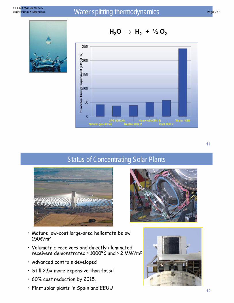
H2O → H2 + ½ O2
Water splitting thermodynamics
12
• Mature low-cost large-area heliostats below150€/m2
.
• Volumetric receivers and directly illuminatedreceivers demonstrated > 1000ºC and > 2 MW/m2
• Advanced controls developed
• Still 2.5x more expensive than fossil
• 60% cost reduction by 2015.
• First solar plants in Spain and EEUU
Status of Concentrating Solar Plants
SFERA Winter School Solar Fuels & Materials Page 287
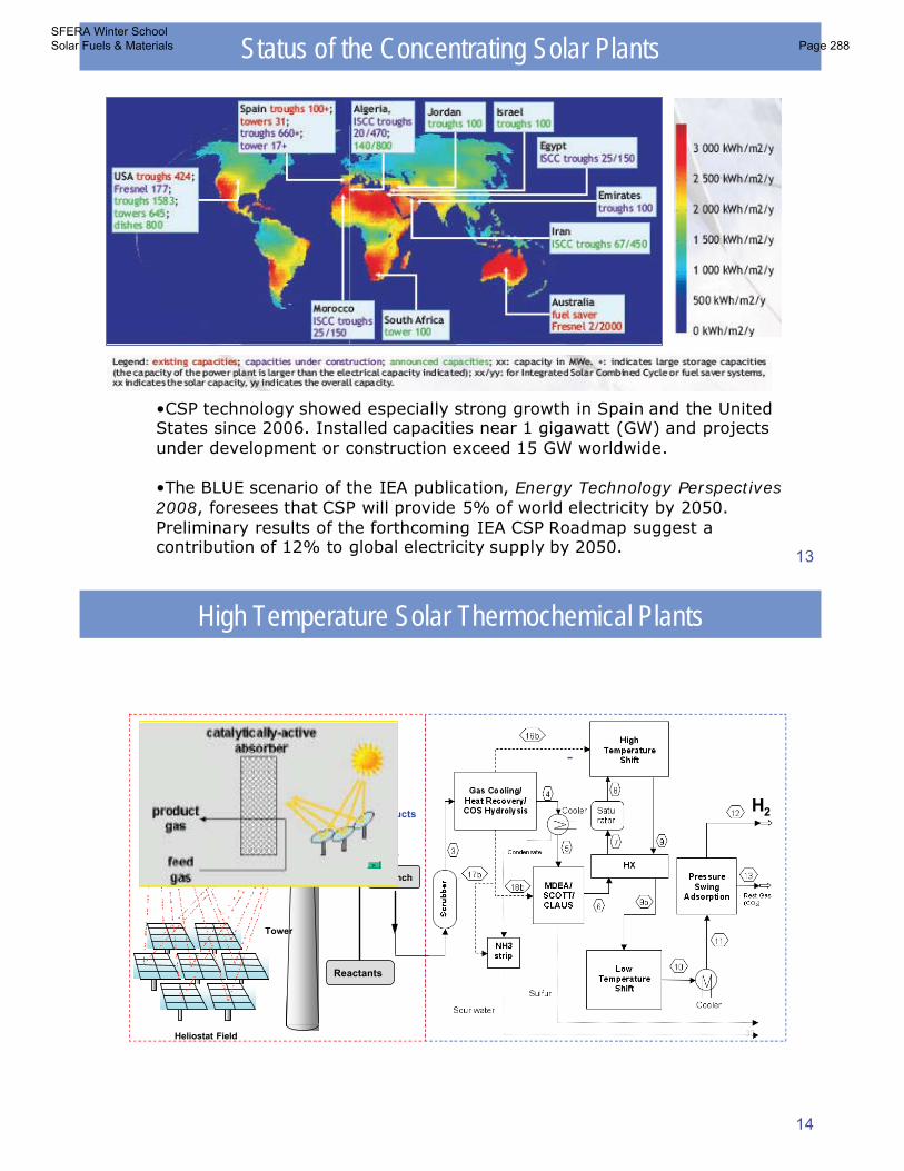
13
•CSP technology showed especially strong growth in Spain and the UnitedStates since 2006. Installed capacities near 1 gigawatt (GW) and projectsunder development or construction exceed 15 GW worldwide.
•The BLUE scenario of the IEA publication, Energy Technology Perspectives2008, foresees that CSP will provide 5% of world electricity by 2050. Preliminary results of the forthcoming IEA CSP Roadmap suggest acontribution of 12% to global electricity supply by 2050.
Status of the Concentrating Solar Plants
14
High Temperature Solar Thermochemical Plants
2
-Solar
Reactor
Large-ScaleConcentration of
Solar Energy
Products
Heliostat Field
Tower
Quench
H
Reactants
SFERA Winter School Solar Fuels & Materials Page 288
15
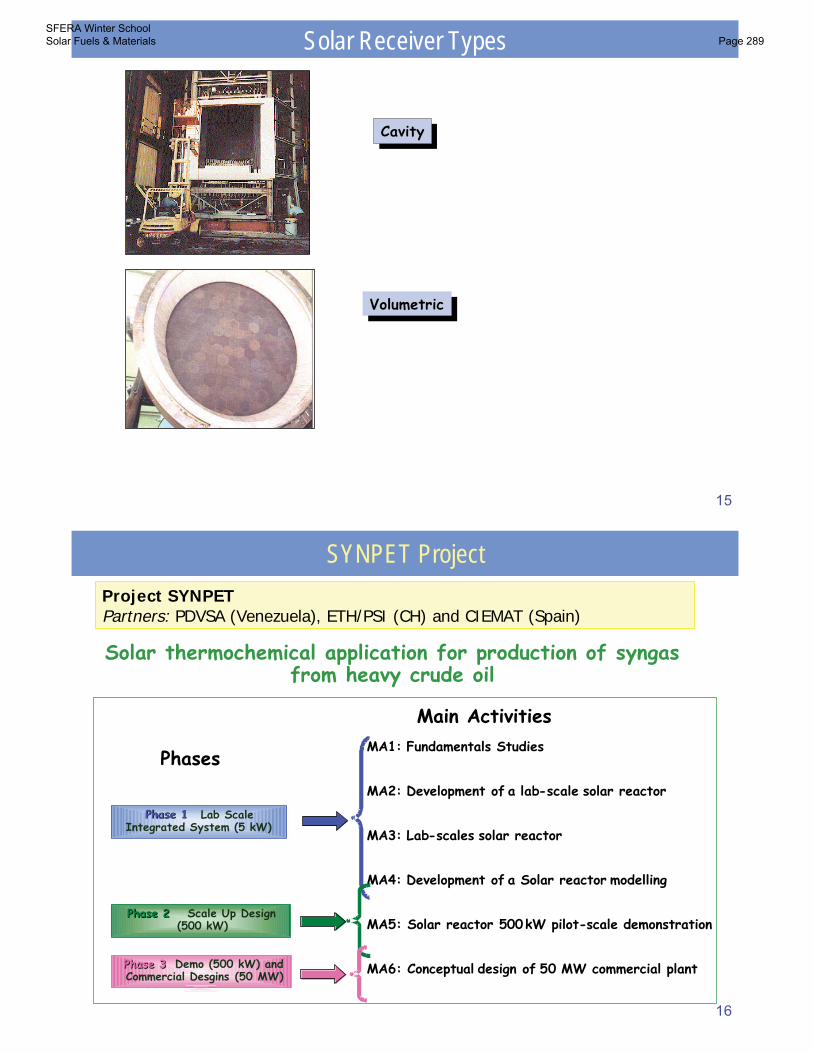
CavityCavityCavity
VolumetricVolumetricVolumetric
Solar Receiver Types
16
MA1: Fundamentals Studies
MA2: Development of a lab-scale solar reactor
MA3: Lab-scales solar reactor
MA4: Development of a Solar reactor modelling
MA5: Solar reactor 500 kW pilot-scale demonstration
MA6: Conceptual design of 50 MW commercial plant
Phase 1Phase 1 Lab ScaleIntegrated System (5 kW)
Phase 2Phase 2 Scale Up Design(500 kW)
Phase 3Phase 3 Demo (500 kW) andCommercial Desgins (50 MW)
Phases
Main Activities
Solar thermochemical application for production of syngas from heavy crude oil
SYNPET ProjectProject SYNPETPartners: PDVSA (Venezuela), ETH/PSI (CH) and CIEMAT (Spain)
SFERA Winter School Solar Fuels & Materials Page 289
17
mol/mol0,012O/C
mol/mol0,56H/C
kJ/kg35.876LHV
%4,16Sulfur
%2,28Nitrogen
%1,47Oxygen
%4,14Hydrogen
%88,12Carbón
UnitsAmountElement
Feedstock: Petroleum coke
18
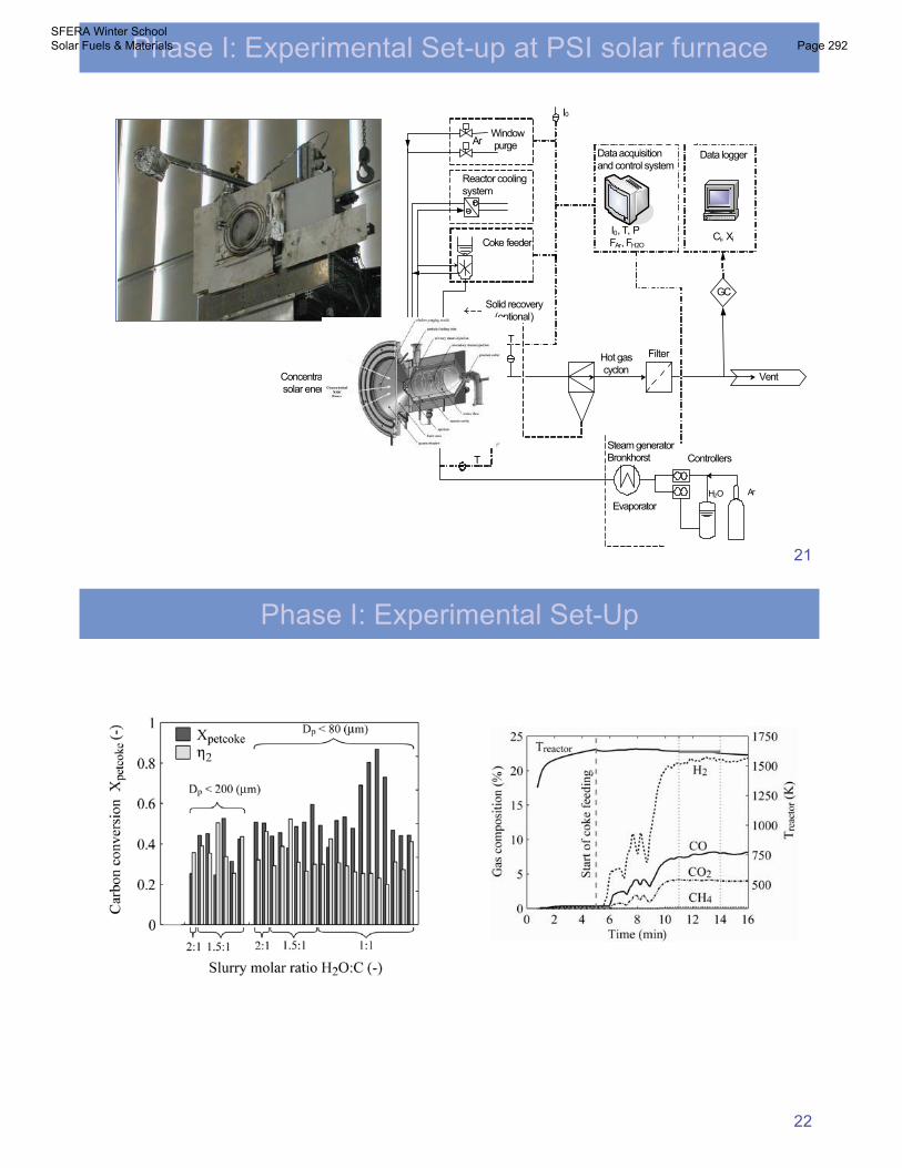
Phase I: Experimental Set-Up
1.09·10-12-2002.92·10-9-125k3 [1/Pa]
1.02·10-666.51.94·10-691.5k2 [mol/(g s Pa)]
4.74·10-31581.05·10-678.9k1 [mol/(g s Pa)]
k0 [ki]EA [kJ/mol]k0 [ki]EA [kJ/mol]
FlexicokePD coke
SFERA Winter School Solar Fuels & Materials Page 290
19
H2
CO
CO2
Flexicoke Petrozuata
Indi
rect
Irrad
iatio
n
Temperature [K] Temperature [K]
Dire
ctIrr
adia
tion
Phase I: Experimental Results
20
Phase I: Reactor and System Modeling
SFERA Winter School Solar Fuels & Materials Page 291
21
Ar
EvaporatorH2O
ControllersSteam generatorBronkhorst
VentConcentratedsolar energy
5 kW Process reactor
Solid recovery(optional)
Data acquisition and control system
T
I0
P
T T TT
Reactor coolingsystem
Hot gascyclon
Filter
Data logger
FAr, FH2O
I0, T, P
Window purge
Coke feeder
GC
Ci, Xi
Ar
Phase I: Experimental Set-up at PSI solar furnace
22
Phase I: Experimental Set-Up
SFERA Winter School Solar Fuels & Materials Page 292
23
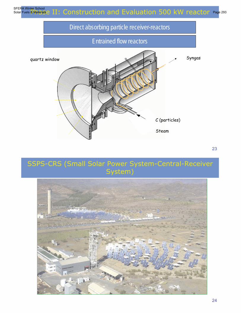
Direct absorbing particle receiver-reactors
Syngas
C (particles)
Steam
quartz window
Entrained flow reactors
Phase II: Construction and Evaluation 500 kW reactor
24
SSPS-CRS (Small Solar Power System-Central-ReceiverSystem)
SFERA Winter School Solar Fuels & Materials Page 293
25
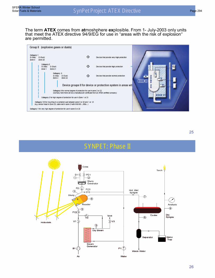
The term ATEX comes from atmoshphere explosible. From 1- July-2003 only unitsthat meet the ATEX directive 94/9/EG for use in “areas with the risk of explosion“are permitted.
SynPet Project: ATEX Directive
26
SYNPET: Phase II
SFERA Winter School Solar Fuels & Materials Page 294
27
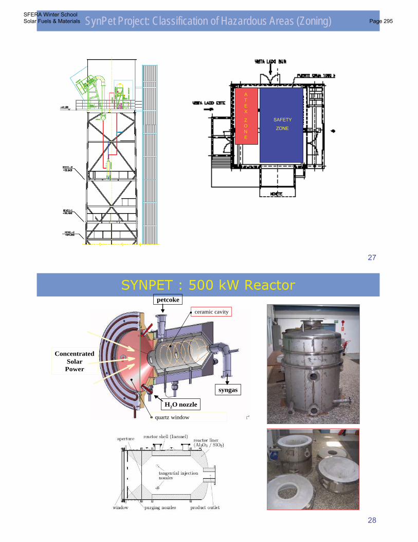
SynPet Project: Classification of Hazardous Areas (Zoning)
SAFETY
ZONE
ATEX
ZONE
28
SYNPET : 500 kW Reactor
ceramic cavity
ConcentratedSolar
Power
quartz window
syngas
petcoke
H2O nozzle
SFERA Winter School Solar Fuels & Materials Page 295
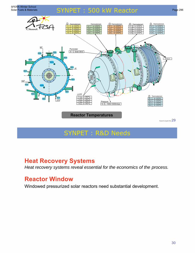
29
90º
0º
180º
270º
Reactor Temperatures
5.1 0-1372ºC5.2 0-1372ºC5.3 0-1372ºC5.4 0-1372ºC
ThermoelementT
4.1 0-1372ºC4.2 0-1372ºC4.3 0-1372ºC4.4 0-1372ºC
ThermoelementT
2.1 0-1372ºC2.2 0-1372ºC2.3 0-1372ºC2.4 0-1372ºC
Thermoelement
3.1 0-1372ºC3.2 0-1372ºC3.3 0-1372ºC3.4 0-1372ºC
ThermoelementT
1.1 0-1372ºC1.2 0-1372ºC1.3 0-1372ºC1.4 0-1372ºC
ThermoelementT
10.1 -1000/+5000mbarPressure
8.1 Solar blind
Pyrometer
7.1 0-1767ºC7.2 0-1767ºC7.3 0-1767ºC7.4 0-1767ºC
LGTP
6.1 0-1372ºC6.2 0-1372ºC6.3 0-1372ºC6.4 0-1372ºC
ThermoelementT
Prepared by Agustín Pérez
TE10-21
TE10
TE10
TE10
TE10
TE10
TE10TE10
TE10
TE10
TE10
TE10
TE10
TE07B
TE07a
SYNPET : 500 kW Reactor
30
SYNPET : R&D Needs
Heat Recovery SystemsHeat recovery systems reveal essential for the economics of the process.
Reactor WindowWindowed pressurized solar reactors need substantial development.
SFERA Winter School Solar Fuels & Materials Page 296
31
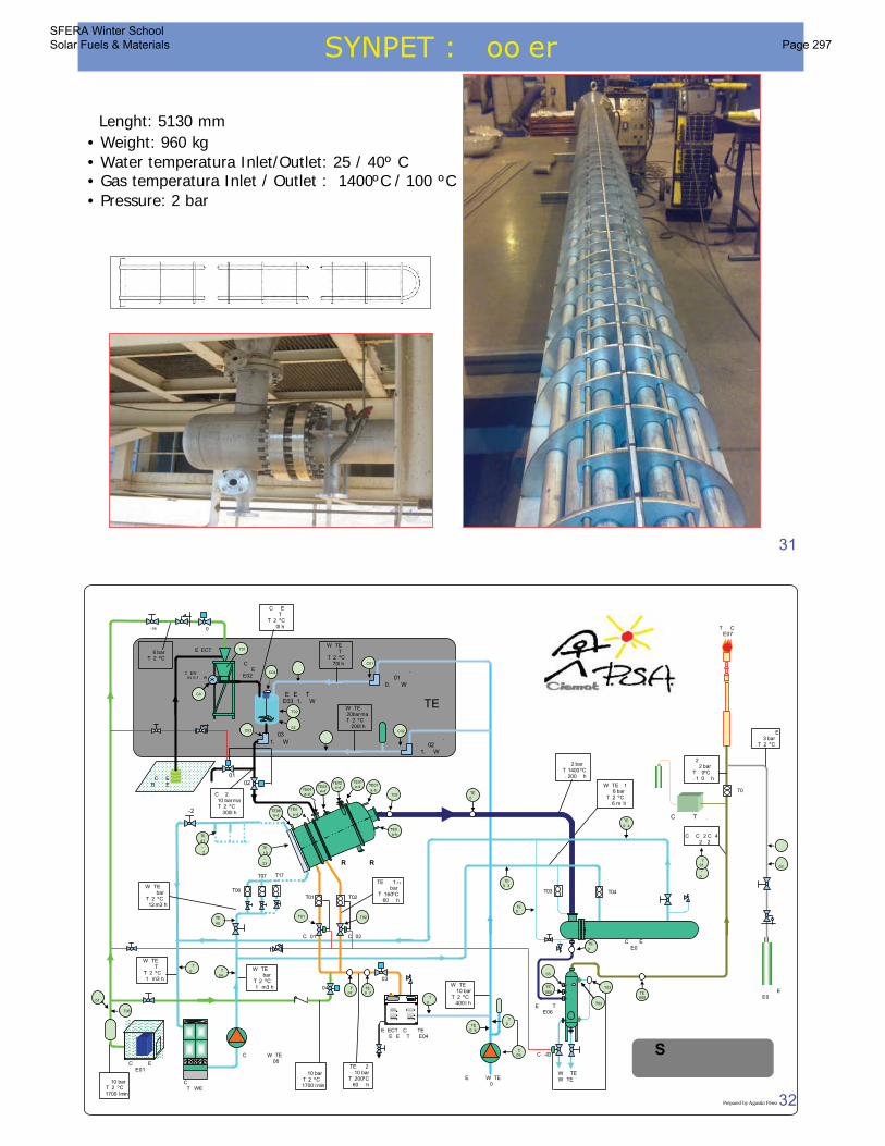
SYNPET : �oo�er
�Lenght: 5130 mm• Weight: 960 kg• Water temperatura Inlet/Outlet: 25 / 40º C• Gas temperatura Inlet / Outlet : 1400ºC / 100 ºC• Pressure: 2 bar
32
�C�EW �����04 0.1� �W
C������ W�TE� ���� �06
�E����� W�TE� �����0�C������
T�WE�
��02
������EE0�
C���E�E0�
W��TEW�TE�
TE
0��
�C�-03
TE
060
���03
�T04�T03
TE0��
TE0�3
TE060
�T0�
������E�� 3 barT� 2�ºC
��������C�� C�2�C�4�
�2��2
T��C�E07
TE
0�4
TE0�6
���� 60
�T0�
�C06
W�TE��� 10 barT� 2�ºC��400 l�h
W�TE��� �T�T� 2�ºC
��1� m3�h
����� 10 barT� 2�ºC
��1700 l�min
�TE�� 2��� 10 barT� 200ºC��60���h
E�ECT��C�� �TE���E�E��T�� E04
�TE�� 1.1�2��� � bar
T� 160ºC��60���h
��
���02
-
0�
TE0��
�T02
�T01 �T02
�C�02�C�01
�T02�T01
��03
��04
��� C����E���E01
���
01
�T06
C��EB���E�
��01
�031.��W
������ �.�02
1.��W
�C02
������ �.�01
0.�� �W
�C01
��
C��E�� �T�T� 2�ºC���0l�h
�������E�E��T��E03 1.� �W
����� 6 barT� 2�ºC
��
R�����R
�-2�
�T06
�T07 �T17
W�TE��� � barT� 2�ºC
��1� m3�h
W�TE��� � barT� 2�ºC
��12 m3�h
��0�
E�ECT��
��C�������E�
E02
�C0�
�2 ����� 2 barT� �0ºC
�. 1�0���h
�E����T��E06
TE0�7
�T07
S���������������
��
�T01
�C04
�������� 2 bar
T� 1400ºC�. 200���h
W�TE� 1��� 6 barT� 2�ºC�. 6 m��h
�C03
�T
0�
�T
0� �T
04
TE
40
TE
41
C��2� ���� 10 bar ma�
T� 2�ºC��300l�h
-
�2TE
10
-33
�-36
Prepared by Agustín Pérez
�����TE�
����� 10 barT� 2�ºC
��1700 l�min
W�TE��� �T�T� 2�ºC��70l�h
W�TE��� 20bar ma�
T� 2�ºC��200l�h
�T02
���02
TE07
a-b
TE0�a-b
�T03
�T03
TE01a-d
TE02a-dTE03
a-dTE04a-d
TE0�
a-dTE06a-d C����T��.
�T01
SFERA Winter School Solar Fuels & Materials Page 297
33
34
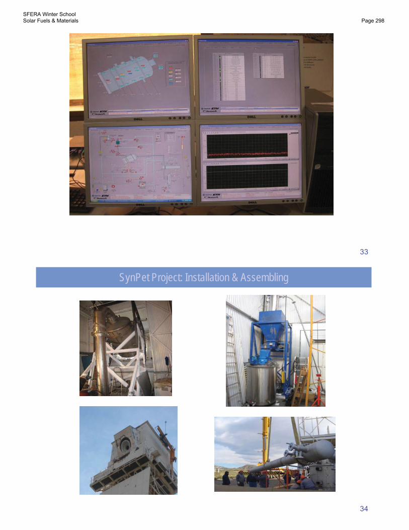
SynPet Project: Installation & Assembling
SFERA Winter School Solar Fuels & Materials Page 298
3�
Test CampaignThe test program includes the following tasks:
Establishing operation procedures, especially for faster start up and shut down (including transition air to steam and steam to steam/coke, and vice versa).
Steady state tests for evaluation of performance (variation of solar flux conditions, mass flow and feed gas composition).
Transient tests (controlled defocus of heliostats). Thermal inertia, response to operating conditions, etc
Thermal evaluation of the heat recovery system and quartz window.
Development of control tools for normal operation in SCADA.
Chemical campaign. Chemical yields and receiver efficiencies, gas composition, maximum hydrogen conversion, etc
36
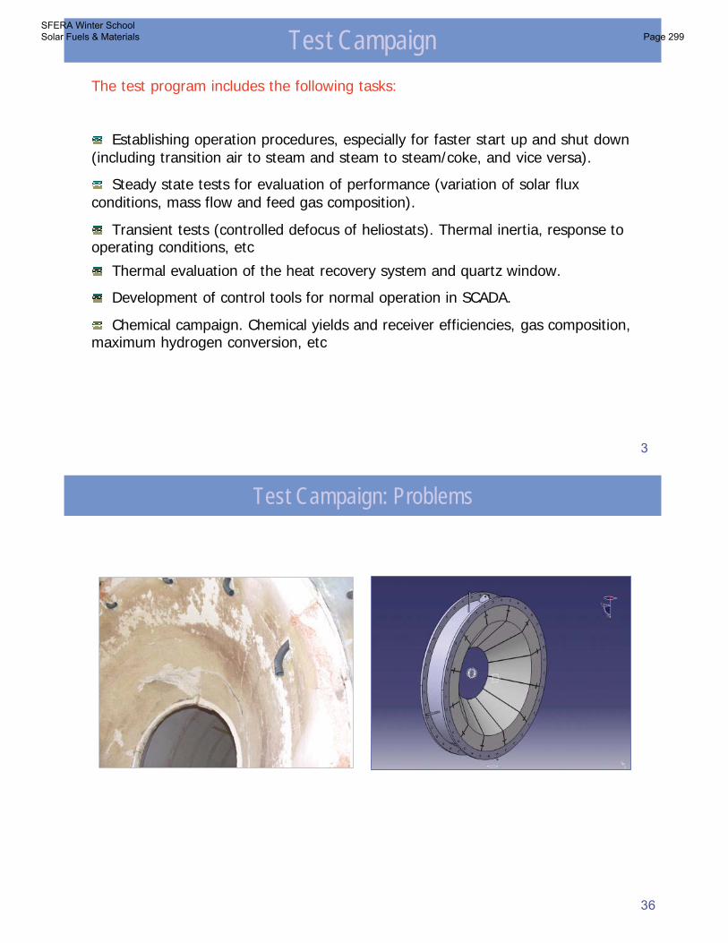
Test Campaign: Problems
SFERA Winter School Solar Fuels & Materials Page 299
37
Conclusions
• Hybrid solar/fossil endothermic processes offer a viable route for reducing CO2emissions and create a transition path towards solar hydrogen
• In view of the importance of coal as a primary source of energy for the foreseeable future and the fact that it is a greenhouse-intensive fuel, it is likely that efforts to incorporate renewable energy, such as solar, into the new coal gasification-basedtechnologies will increase in the future.
• The world is facing rapid growth in energy demand, persistently high energy prices, and a challenge to reduce carbon dioxide emissions from power generation and manufacturing. No single technology or resource can solve the problem, but gasification can be part of the solution along with oter technologies and energy efficiency programs.
• Solar Gasification offers the opportunity to solve one of the most important problemsof solar technology, that is, to provide an effective means of storage. Furthermore, thethermochemical plant could be run producing hydrogen all day and ccoupled with aIGCC to produce power, with the main advantage that could be in operation all day
Solar Gasification
3�
SFERA Winter School Solar Fuels & Materials Page 300


![L F G I J K C M H D A E B - Electric Vehicles · 10 kWh [ km ] 72 (The max autonomy value reported is indicative and refers to homologation data collected on WLTP cycle basis (combined](https://static.fdocument.org/doc/165x107/5fff7b4ebb1b311d70236d36/l-f-g-i-j-k-c-m-h-d-a-e-b-electric-vehicles-10-kwh-km-72-the-max-autonomy.jpg)