
Final Report: Design and Development of an Automated ...
39
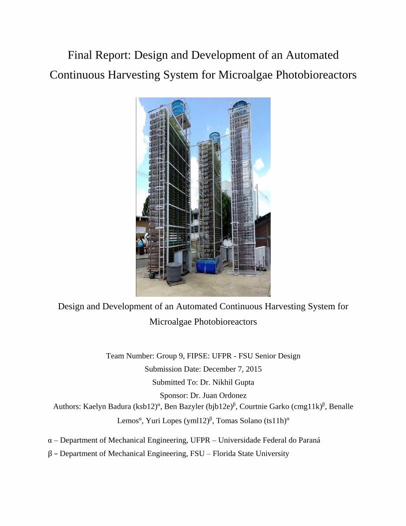
Final Report: Design and Development of an Automated Continuous Harvesting System for Microalgae Photobioreactors Design and Development of an Automated Continuous Harvesting System for Microalgae Photobioreactors Team Number: Group 9, FIPSE: UFPR - FSU Senior Design Submission Date: December 7, 2015 Submitted To: Dr. Nikhil Gupta Sponsor: Dr. Juan Ordonez Authors: Kaelyn Badura (ksb12) α , Ben Bazyler (bjb12e) β , Courtnie Garko (cmg11k) β , Benalle Lemos α , Yuri Lopes (yml12) β , Tomas Solano (ts11h) α α – Department of Mechanical Engineering, UFPR – Universidade Federal do Paraná β – Department of Mechanical Engineering, FSU – Florida State University
Transcript of Final Report: Design and Development of an Automated ...
Final Report: Design and Development of an Automated
Continuous Harvesting System for Microalgae Photobioreactors
Design and Development of an Automated Continuous Harvesting System for
Microalgae Photobioreactors
Team Number: Group 9, FIPSE: UFPR - FSU Senior Design
Submission Date: December 7, 2015
Submitted To: Dr. Nikhil Gupta
Sponsor: Dr. Juan Ordonez
Authors: Kaelyn Badura (ksb12)α, Ben Bazyler (bjb12e)β, Courtnie Garko (cmg11k)β, Benalle
Lemosα, Yuri Lopes (yml12)β, Tomas Solano (ts11h)α
α – Department of Mechanical Engineering, UFPR – Universidade Federal do Paraná
β – Department of Mechanical Engineering, FSU – Florida State University
AUTOMATED CONTINUOUS HARVESTING SYSTEM FOR MICROALGAE PHOTOBIOREACTORS
i
CONTENTS PAGE
Table of Contents Page
I. Problem Statement...………………………………………………...…………………1
1. Background Information...………………………………………………………………...1
2. Current State of Relevant Technologies…………………………………………………..2
II. Project Scope………………….…………………………………………...……….…...3
1. Key Technical Considerations………………………..…………………………………...3
2. Goal Statement………....………………………………………………………………….4
3. Project Objectives……………………………………………………….….…….……….4
4. Project Constraints………………………………………………………………………...4
III. Product Specifications…………...……………………………………………………5
1. Design Specification………………………………………………………………………5
2. Performance Specifications……………………………………………………………….6
IV. Methodology and Design Approach................................................................6
1. Literature Review and Design…………………………………………………………….7
2. Testing and Validation……………………………………………...……………………..8
3. Construction and Implementation……………..……………………………………..……9
V. Concept Generation and Selection…………………………………………………10
1. Cultivation Initiative...…………………..……………………………………………….10
2. Harvesting Initiative………..…………………………………………………………….12
VI. Health and Environmental Safety……......…...……………………………………17
VII. Logistics………………………………………………………………………………..17
1. Challenge Identification …………………………………………………………………17
2. Risk Assessment…………………………………………………………………………18
3. Schedule and Resource Allocation………………………………………………………18
VIII. Conclusion……………………………………………………………………………..19
IX. Acknowledgements………………..…………………………………………………20
X. References……………………………..……………………………………………….20
XI. Appendices………………..…………………………...………………………………21
AUTOMATED CONTINUOUS HARVESTING SYSTEM FOR MICROALGAE PHOTOBIOREACTORS
ii
Table of Figures Page
1. General Design………...……………………………………………….…….…………...6
2. Actual Subsystems……………………...…………………………………………………7
3. House of Quality………………………...………………………………………………...8
4. Morphological Chart – Cultivation……………………………………………...……….11
5. Decision Matrix – Cultivation…………………………………………………..……….12
6. Option 2 selected for design component - Cultivation……..…………………………....12
7. Morphological Chart – Harvesting..………..…………………………...……………….13
8. Decision Matrix –Harvesting..…………………………………………………………...14
9. Option 1 selected for design component – Harvesting………………….….…….……...14
10. CAD Model of Lysing Component……………………………………………………....16
11. Diagram of electrical circuit for Lysing……………………………...…………………..16
12. Gantt Chart….………………………………………………………………………........19
Table of Tables Page
1. Tanfloc Sedimentation Test...…………………………………………………….………..9
2. Chitosan Sedimentation Test………………………………………………………………9
AUTOMATED CONTINUOUS HARVESTING SYSTEM FOR MICROALGAE PHOTOBIOREACTORS
1
I. Problem Statement
As a result of waning fossil fuel resources it is desirable to have access to a sustainable
alternative energy source. Microalgae photobioreactors are viable options for simple and
sustainable energy source production. The operation of these bioreactors has the potential for
automation and produces environmentally friendly biomass and biogas which have many
widespread applications, as aforementioned. The current state of microalgae photobioreactors is
very dependent on consistent maintenance and check-ups to keep the algae growing. In addition,
there are no viable methods for automated harvesting of the microalgae. This is unsatisfactory
because it limits the scope of utilizing microalgae as a large scale biofuel source. UFPR in
conjunction with FSU are sponsoring the Senior Design team to develop a continuous harvesting
system which requires minimal intervention as a solution to the harvesting problem.
1. Background Information
“Technology for producing and using biodiesel has been known for more than 50 years”1
Research in potential biodiesels such as soybeans, animal fats, and vegetable oils have opened a
large field of study into alternative natural fuel sources and mass production of these renewable
resources1,2. Microalgae have emerged as a highly sought alternative fuel and point of biodiesel
production due to their high growth rate, use of available natural resources such as solar radiation
and CO2 , and can be produced using a minimal amount of non-arable land. This is extremely
important as it indicates the potential for usable microalgae to be produced efficiently all while not
impacting the agricultural capacity of a location. Additionally, microalgae are resilient and tolerate
a relatively wide range of growth conditions. One observation which follows from the versatility
of the microalgae is the potential to cultivate algae in reclaimed agriculture or municipal water.2
This has led to the conclusion that microalgae is not only a potential biofuel resource, but that it
can become a method to recycle and clarify used water. Additionally, produced biomass can also
be utilized as a food stock, as a source for dyes, medical applications, and more.2
For many years, FSU-FAMU College of Engineering has partnered with the Federal
University of Paraná’s Center for Research and Development of Self-Sustainable Energy
(NPDEAS). NPDEAS is a research lab in Curitiba, Brazil that focuses on the growth,
enhancement, production, and application of microalgae, a product that can be used as an
alternative fuel source. Recently, research in both facilities has been done to try and optimize the
growth of algae in an attempt to discover the most efficient environment and process of cultivating
the biomass. Previous FSU- FAMU Senior Design groups along with the help of Dr. Juan Ordonez
have spent many hours researching the most effective levels of CO2, the proper angle of flasks set
for maximum algal growth, peak points in growth, time required in the photobioreactor and many
smaller aspects that contribute to efficient biomass production. Both small and large scale
AUTOMATED CONTINUOUS HARVESTING SYSTEM FOR MICROALGAE PHOTOBIOREACTORS
2
harvesting plants have been designed and are currently in use to cultivate microalgae around the
world. All previous research and microalgae system developments have been batch,
semicontinuous, partially or non-autonomous until now and no groups have attempted to design
an continuous and fully automated system that will increase production, maximize time efficiency,
and lessen the need for human interference to keep the biomass production running.
Further research done by engineers such as Yusuf Chisti1, Sina Salim, and many others has
helped to contribute to knowledge on cultivation, flocculation, harvesting microalgae,
photobioreactor engineering, and the potential uses of microalgal biomass. Their published works
including “Biodiesel from Microalgae”1, “Flocculation as a low-cost method for harvesting
microalgae for bulk biomass production”2, and other similar papers have helped to better the
understanding of the entire process and the future economical improvements that can be made by
using microalgae biomass in place of diesel fuels.
2. Current State of Relevant Technologies
Currently, there are few gaps in the actual production of biomass from microalgae,
nonetheless, extensive research is being performed on how to best produce and utilize microalgae.
On a broad scale, growth and cultivation has been generally optimized, however, there is still an
observable lack of standardization between the used cultivation setup and cultivation parameters.
The most common process for the growth and harvest of microalgae consists of cultivation,
flocculation, coagulation, clarification (also called sedimentation) and extraction. 1,2,3
Cultivation of microalgae can occur in two ways: open or closed. The most common
example of open cultivation is the usage of natural bodies of water or artificial ponds. The
advantages to using an open system include the usage of natural water, available sunlight, and ease
and cost efficiency of installation and operation.3 However, open systems face many issues
including contamination and difficulties with the control of nutrients, light, and CO2 supply. Open
systems, such as raceway ponds also require large land area adding an extra cost. Closed systems
can be artificially or naturally illuminated, can be implemented inside or outside, offer more
reliable culture condition control, and can be compact in order to increase space efficiency. 3 One
disadvantage to utilizing a closed system is that they can be more expensive and require more
maintenance. Common examples of closed cultivation systems include airlifts and
photobioreactors.3
Harvesting of microalgae is a multistep process which involves flocculation, coagulation,
clarification, and extraction.2,4 Flocculation is the process by which algae cells are automatically,
chemically, or otherwise modified so they will conglomerate into larger clumps of algae cells
known as ‘flocs’.4 Flocculation also typically involves lower speed mixing, while coagulation
usually entails the usage of higher speed mixing, however for some processes flocculation and
coagulation can be combined as one process with a longer duration. During automatic flocculation,
algal cells naturally coagulate and sediment most commonly due to changes in cultivation pH as a
AUTOMATED CONTINUOUS HARVESTING SYSTEM FOR MICROALGAE PHOTOBIOREACTORS
3
result of microalgal CO2 consumption.4,5,6 Automatic flocculation is relatively simple and
inexpensive, however it is less time efficient than other methods. Chemical flocculation relies on
the addition of chemicals which are used to manually neutralize the charge on the exterior of the
microalgal cells and usually uses iron, aluminum, magnesium, and calcium. Chemical flocculation
is more time efficient than automatic flocculation but requires the usage of chemicals and,
depending on the intended application of the produced biomass, an additional purification process
to remove residual flocculant.4 Other methods which can also be utilized to flocculate the
microalgae include filtration, centrifugation, electroflotation, and electroflocculation.
Electroflocculation will be focused on as an alternative flocculation method due to its relevance to
this project.
Interest in the method of biomass flocculation called electroflocculation has occurred
recently. This is an electrical process by which the charge of the suspended particles are neutralized
allowing them to come close enough together that they coagulate due to the Van Der Waals
attraction or even form hydrogen bonds. Once the suspended particles i.e algae cells, have
coagulated, they become heavy enough to sediment. The process of electroflocculation requires
two “sacrificial” anodes that will provide the ions needed to neutralize the cells. The anodes are
connected to a power source and placed in the volume of culture to be flocculated. Pulses of
electricity at low voltage (5V-30V) are applied causing the neutralization and therefore
sedimentation.
II. Project Scope
1. Key Technical Considerations
This is a fundamentally interdisciplinary project which fuses heavily weighted
mechanical engineering concepts including control volume flow and flow control with chemical
engineering, and life sciences.
There are many pressing ideas, concepts, and processes which need to be considered during
the development and execution of this design project. There are five main technical considerations
which will direct the evolution of this project.
These five key technical considerations include:
● Standardization of cultivation process and procedure.
● The design of a larger than laboratory scale enclosed cultivation system which effectively
demonstrates scalability of laboratory scale proof of concept.
● Investigation and optimization of time required to harvest 1 gram of algal biomass per
liter of culture.
● Optimization of space efficiency of developed design to keep space usage to a minimum
AUTOMATED CONTINUOUS HARVESTING SYSTEM FOR MICROALGAE PHOTOBIOREACTORS
4
● Creation of a minimal to no loss system characterized by the reuse of recycled medium.
2. Goal Statement
The goal statement specified within a project outlines the general aims of the project. For
Group 9, the FIPSE: FSU – UFPR Senior design team, the goal statement is given below.
Goal Statement: “Design of an automated and continuous harvesting system for microalgae”
3. Project Objectives
Objectives are tangible milestones against which to gauge progress and quantify success
in fulfilling the outlined goal. The relevant objectives for the design of an automated and
continuous harvesting system for microalgae are defined below.
● Biomass production process must be fully automated.
○ From cultivation through collection and flocculation to separation.
● System must have ability to separate produced biomass and clarified water.
● Must work for batch, semicontinuous, and continuous collection.
● Must incorporate continuous flocculation and sedimentation.
● Must be sustainable, both in construction and in process.
○ Minimized energy and resource consumption.
● System must be scalable and will show functionality at both lab and pilot scales.
● Harvesting system will work with different species of algae.
4. Project Constraints
These are requirements potential designs must meet in order to be fully considered as a
legitimate and appropriate design which meets sponsor’s expectations. There are eight main
logistical and technical constraints outlined for the design and development of an automated and
continuous harvesting system for microalgae photobioreactors.
● The developed system must work with FSU’s current skeleton photobioreactor
infrastructure.
● The total cost may not exceed $1,500.
● The clarified medium must be recyclable.
● The produced biomass must remain usable (aimed towards the production of biodiesel) and
should require no additional purification.
AUTOMATED CONTINUOUS HARVESTING SYSTEM FOR MICROALGAE PHOTOBIOREACTORS
5
● Harvesting process should be continuous, with the option of batch or semi-continuous
operation, and requires minimal human interaction.
● Entire laboratory scale system must be less than 10 m2 and should accommodate at most,
10 L in cultivation and sedimentation chambers.
● The entire system’s flow rate will be dictated by the growth rate of the utilized microalgae.
The growth rate of each algae is different and therefore the system must be able to adapt.
● Developed system must function in various environments and be able to maintain a
cultivation temperature of 16-27 °C.
III. Product Specifications
1. Design Specifications
For this project, the goal is to have two fully functioning systems of different scales. The
first system will be designed for commercial and educational research purposes and will be
restrained to the size of an average table, less than 10 m2, for usage in simple lab settings. The
laboratory, or ‘table-top’, scale of the system will serve as a proof of concept of the system
functionality. The main objective of this system, aside from functional proof of concept, is to
provide interested parties with a continuous and low maintenance supply of algae biomass for
research and other relevant applications. This means that the biomass cannot be contaminated,
should not require an additional purification process, the system should be fully automated and
should require minimal maintenance. The second system will be created for quasi-industrial
purposes and applications and will make use of a mini-photo bioreactor. This scaled up version of
the system will serve as proof of scalability, to ultimately industrial scale photobioreactors (12,000
L). The main objective associated with the scaled up system is to provide a continuous means of
biomass extraction while increasing production and efficiency as well as eliminating post-
processing of the product.
Constraints have been overviewed in a previous section. These project constraints dictate
the design specifications. The major consideration that are related to innovation within this system
are minimizing production time, minimizing or elimination of post-processing and minimizing
space usage. Additionally the required continuous regime of biomass extraction is vital to design
specifications, and is discussed further in Performance Specifications.
AUTOMATED CONTINUOUS HARVESTING SYSTEM FOR MICROALGAE PHOTOBIOREACTORS
6
2. Performance Specifications
The performance specifications are heavily linked to design specifications as form and
function are always related. The performance of the systems (tabletop and quasi-industrial) is
governed by the need for the automatic and continuous production of biomass. The system must
cultivate and harvest the algae with minimal human interference and maintenance. The collection
of the produced biomass must be immediate and in a manner that will avoid a short circuit to the
system i.e overflow, backflow, and algal contamination of recycled medium. More specific to the
large scale, quasi-industrial system is the minimization of post-processing. The final products
desired is ‘fatty’ biomass for the production of biodiesel and biomass for animal feed. This
signifies that if possible biomass centrifugation or the addition of chemical flocculants should be
bypassed.
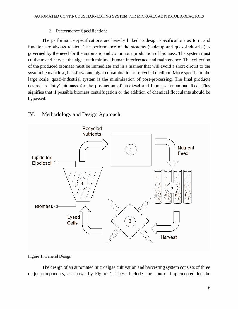
IV. Methodology and Design Approach
Figure 1. General Design
The design of an automated microalgae cultivation and harvesting system consists of three
major components, as shown by Figure 1. These include: the control implemented for the
AUTOMATED CONTINUOUS HARVESTING SYSTEM FOR MICROALGAE PHOTOBIOREACTORS
7
automation of the system which is composed of the microcontroller, source code, and actuators;
cultivation which consists of medium preparation and disbursement, the cultivation tank, and
culture conditions such as illumination and aeration distribution; lastly is the harvesting component
which is comprised of the flocculation, sedimentation, and extraction of biomass products. (See
Figure 3 for a conglomeration of the actual subsystems used for this project.)
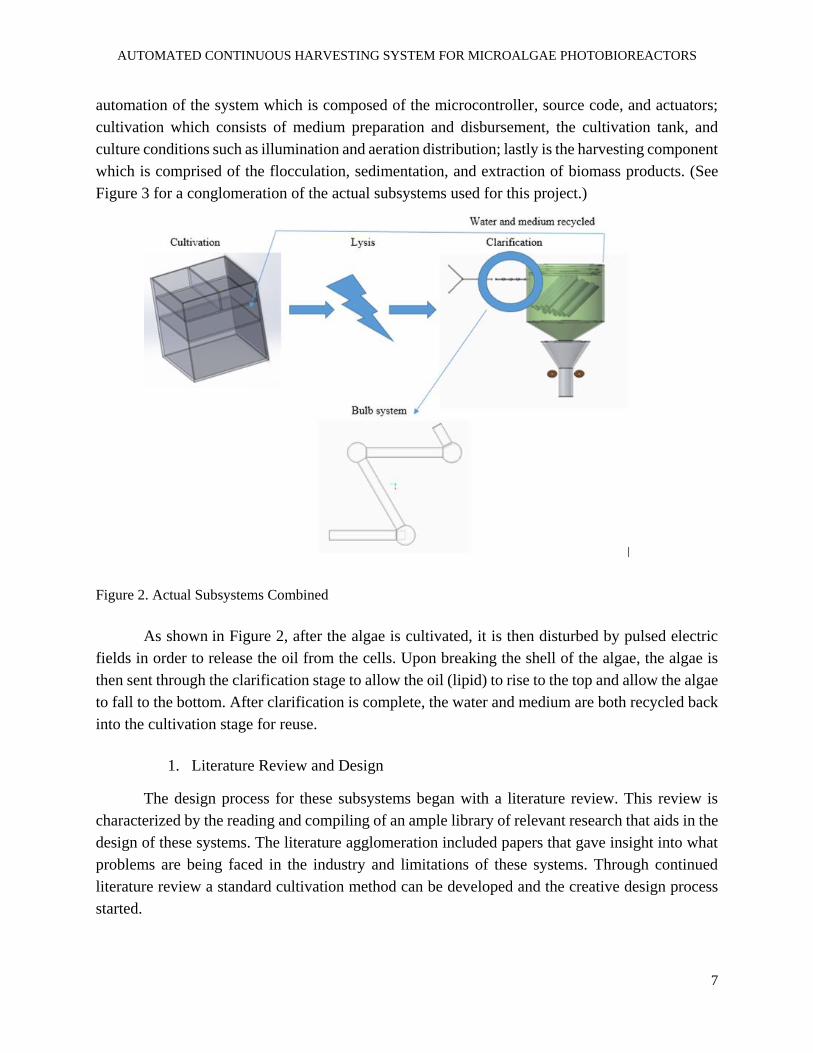
Figure 2. Actual Subsystems Combined
As shown in Figure 2, after the algae is cultivated, it is then disturbed by pulsed electric
fields in order to release the oil from the cells. Upon breaking the shell of the algae, the algae is
then sent through the clarification stage to allow the oil (lipid) to rise to the top and allow the algae
to fall to the bottom. After clarification is complete, the water and medium are both recycled back
into the cultivation stage for reuse.
1. Literature Review and Design
The design process for these subsystems began with a literature review. This review is
characterized by the reading and compiling of an ample library of relevant research that aids in the
design of these systems. The literature agglomeration included papers that gave insight into what
problems are being faced in the industry and limitations of these systems. Through continued
literature review a standard cultivation method can be developed and the creative design process
started.
AUTOMATED CONTINUOUS HARVESTING SYSTEM FOR MICROALGAE PHOTOBIOREACTORS
8
The creative design process consisted of breaking down the systems into the major
components. Once the components were identified, research was conducted on how the
components operate and how they can be substituted or omitted. Taking advantage of the six group
members each member of the team presented his or her own unique ideas and designs for each
component. Once the designs had been generated through the morphological method and
compiled, the decision on which design was to be used, was finalized. These decisions were
reached with the aid of decision (Pugh) matrices. These tools served to narrow available options
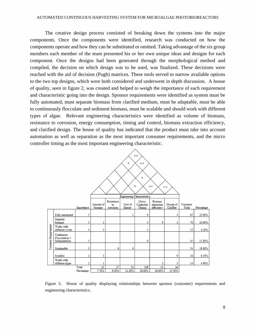
to the two top designs, which were both considered and underwent in depth discussion. A house
of quality, seen in figure 2, was created and helped to weigh the importance of each requirement
and characteristic going into the design. Sponsor requirements were identified as system must be
fully automated, must separate biomass from clarified medium, must be adaptable, must be able
to continuously flocculate and sediment biomass, must be scalable and should work with different
types of algae. Relevant engineering characteristics were identified as volume of biomass,
resistance to corrosion, energy consumption, timing and control, biomass extraction efficiency,
and clarified design. The house of quality has indicated that the product must take into account
automation as well as separation as the most important consumer requirements, and the micro
controller timing as the most important engineering characteristic.
Figure 3. House of quality displaying relationships between sponsor (customer) requirements and
engineering characteristics.
AUTOMATED CONTINUOUS HARVESTING SYSTEM FOR MICROALGAE PHOTOBIOREACTORS
9
2. Testing and Validation
In order to be able to use the mini photobioreactor, it must first be tested for leaks and made
sure to be sterile so that the algae can successfully grow. In regards to the flocculations, once the
design was finalized, several tests needed be done to dimensionalize the components. Although
chemical flocculation is the main candidate thus far for the flocculation other methods are being
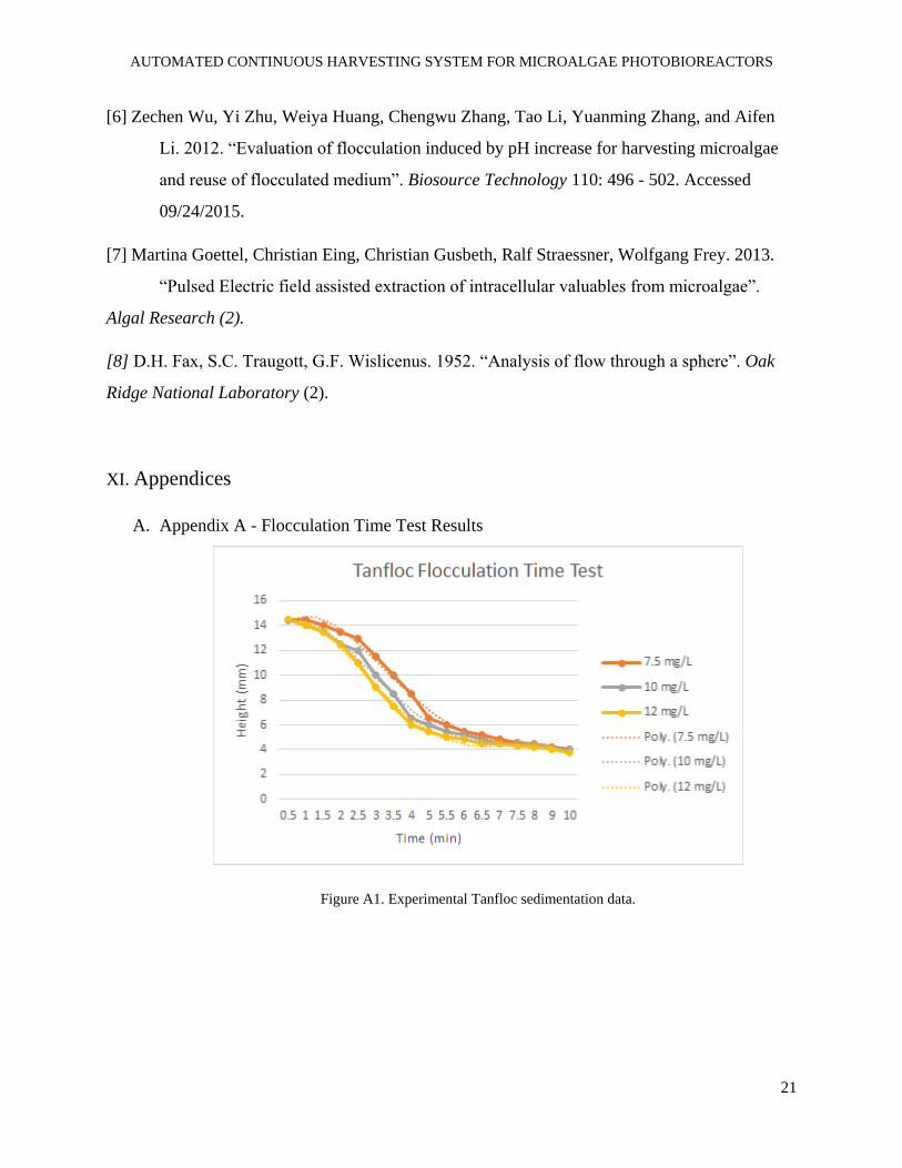
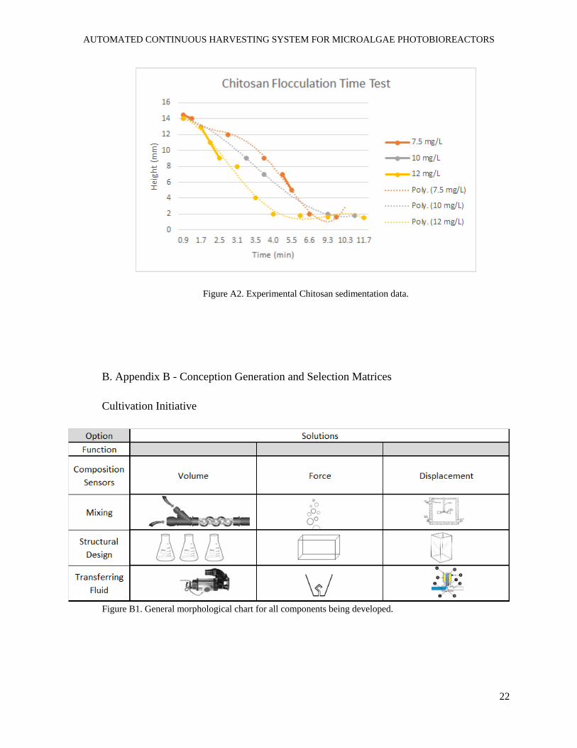
considered. Sedimentation rate tests were conducted with two commonly used chemical
flocculants. Tanfloc and Chitosan were tested at four different concentrations to determine clarity
and flocculation (sedimentation) rates and time. All results were estimated for the sake of baseline
visualization to be considered when choosing the flocculation procedure. Algal column heights
were recorded every 30 seconds to 1 minute and these data points were used to find an appropriate
fit. This trendline was then integrated with respect to time and divided by total experiment time
in order to generate settling velocity. End clarity of the water following flocculation was recorded
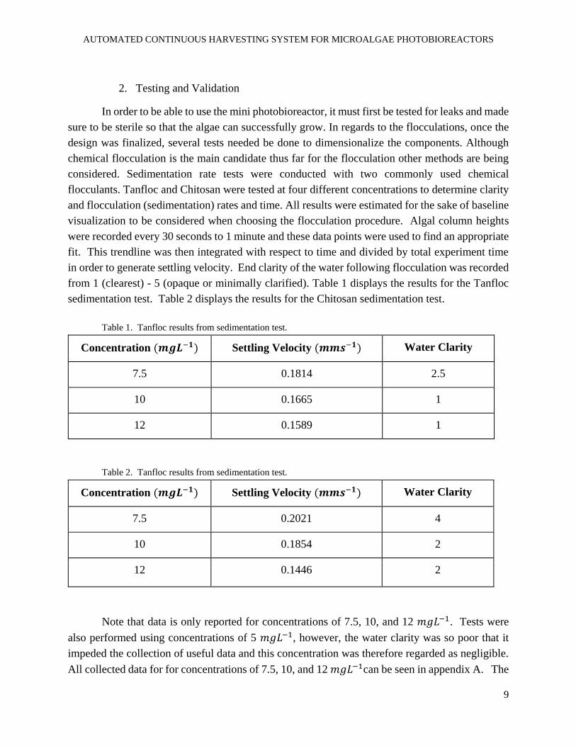
from 1 (clearest) - 5 (opaque or minimally clarified). Table 1 displays the results for the Tanfloc
sedimentation test. Table 2 displays the results for the Chitosan sedimentation test.
Table 1. Tanfloc results from sedimentation test.
Concentration (𝒎𝒈𝑳−𝟏) Settling Velocity (𝒎𝒎𝒔−𝟏) Water Clarity
7.5 0.1814 2.5
10 0.1665 1
12 0.1589 1
Table 2. Tanfloc results from sedimentation test.
Concentration (𝒎𝒈𝑳−𝟏) Settling Velocity (𝒎𝒎𝒔−𝟏) Water Clarity
7.5 0.2021 4
10 0.1854 2
12 0.1446 2
Note that data is only reported for concentrations of 7.5, 10, and 12 𝑚𝑔𝐿−1. Tests were
also performed using concentrations of 5 𝑚𝑔𝐿−1, however, the water clarity was so poor that it
impeded the collection of useful data and this concentration was therefore regarded as negligible.
All collected data for for concentrations of 7.5, 10, and 12 𝑚𝑔𝐿−1can be seen in appendix A. The
AUTOMATED CONTINUOUS HARVESTING SYSTEM FOR MICROALGAE PHOTOBIOREACTORS
10
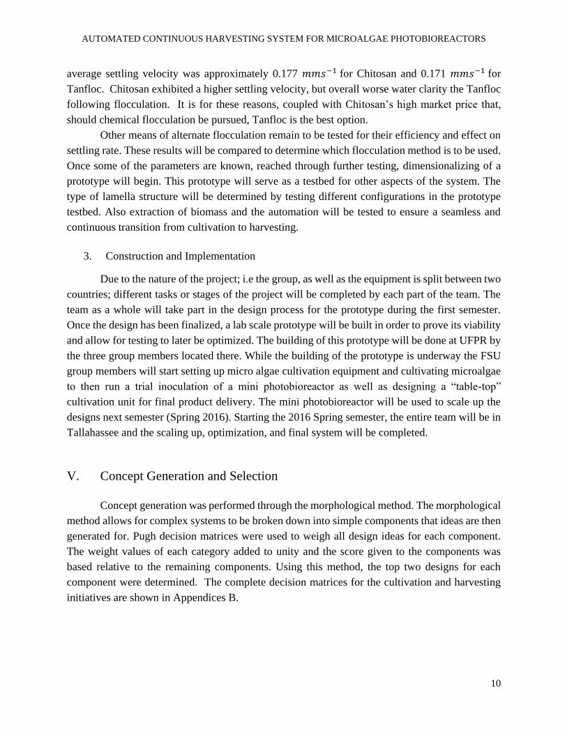
average settling velocity was approximately 0.177 𝑚𝑚𝑠−1 for Chitosan and 0.171 𝑚𝑚𝑠−1 for
Tanfloc. Chitosan exhibited a higher settling velocity, but overall worse water clarity the Tanfloc
following flocculation. It is for these reasons, coupled with Chitosan’s high market price that,
should chemical flocculation be pursued, Tanfloc is the best option.
Other means of alternate flocculation remain to be tested for their efficiency and effect on
settling rate. These results will be compared to determine which flocculation method is to be used.
Once some of the parameters are known, reached through further testing, dimensionalizing of a
prototype will begin. This prototype will serve as a testbed for other aspects of the system. The
type of lamella structure will be determined by testing different configurations in the prototype
testbed. Also extraction of biomass and the automation will be tested to ensure a seamless and
continuous transition from cultivation to harvesting.
3. Construction and Implementation
Due to the nature of the project; i.e the group, as well as the equipment is split between two
countries; different tasks or stages of the project will be completed by each part of the team. The
team as a whole will take part in the design process for the prototype during the first semester.
Once the design has been finalized, a lab scale prototype will be built in order to prove its viability
and allow for testing to later be optimized. The building of this prototype will be done at UFPR by
the three group members located there. While the building of the prototype is underway the FSU
group members will start setting up micro algae cultivation equipment and cultivating microalgae
to then run a trial inoculation of a mini photobioreactor as well as designing a “table-top”
cultivation unit for final product delivery. The mini photobioreactor will be used to scale up the
designs next semester (Spring 2016). Starting the 2016 Spring semester, the entire team will be in
Tallahassee and the scaling up, optimization, and final system will be completed.
V. Concept Generation and Selection
Concept generation was performed through the morphological method. The morphological
method allows for complex systems to be broken down into simple components that ideas are then
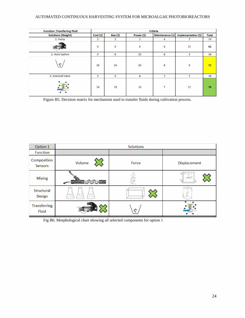
generated for. Pugh decision matrices were used to weigh all design ideas for each component.
The weight values of each category added to unity and the score given to the components was
based relative to the remaining components. Using this method, the top two designs for each
component were determined. The complete decision matrices for the cultivation and harvesting
initiatives are shown in Appendices B.
AUTOMATED CONTINUOUS HARVESTING SYSTEM FOR MICROALGAE PHOTOBIOREACTORS
11
1. Cultivation Initiative
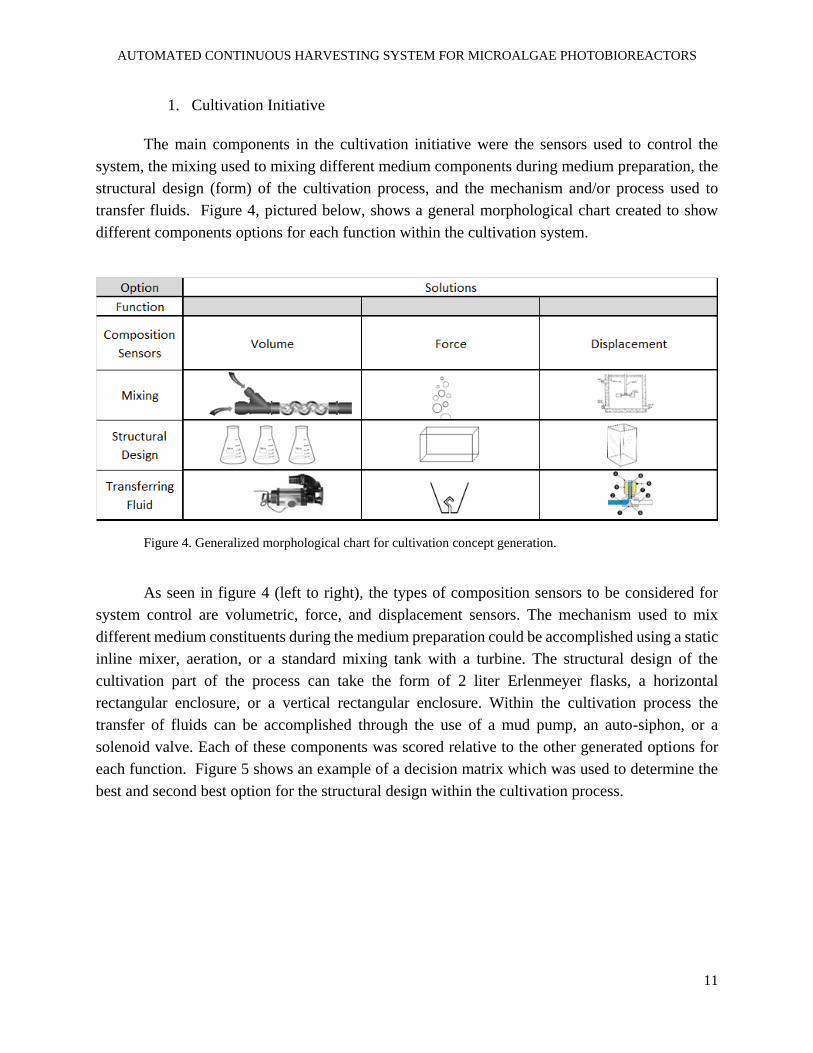
The main components in the cultivation initiative were the sensors used to control the
system, the mixing used to mixing different medium components during medium preparation, the
structural design (form) of the cultivation process, and the mechanism and/or process used to
transfer fluids. Figure 4, pictured below, shows a general morphological chart created to show
different components options for each function within the cultivation system.
Figure 4. Generalized morphological chart for cultivation concept generation.
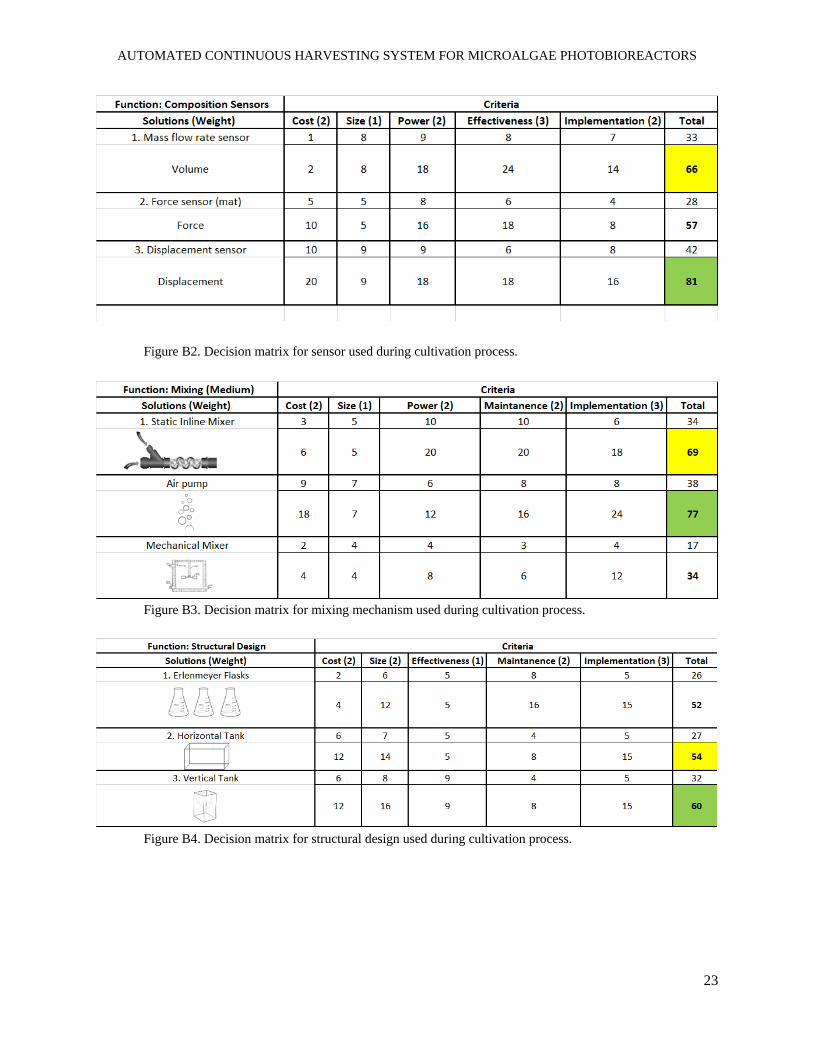
As seen in figure 4 (left to right), the types of composition sensors to be considered for
system control are volumetric, force, and displacement sensors. The mechanism used to mix
different medium constituents during the medium preparation could be accomplished using a static
inline mixer, aeration, or a standard mixing tank with a turbine. The structural design of the
cultivation part of the process can take the form of 2 liter Erlenmeyer flasks, a horizontal
rectangular enclosure, or a vertical rectangular enclosure. Within the cultivation process the
transfer of fluids can be accomplished through the use of a mud pump, an auto-siphon, or a
solenoid valve. Each of these components was scored relative to the other generated options for
each function. Figure 5 shows an example of a decision matrix which was used to determine the
best and second best option for the structural design within the cultivation process.
AUTOMATED CONTINUOUS HARVESTING SYSTEM FOR MICROALGAE PHOTOBIOREACTORS
12
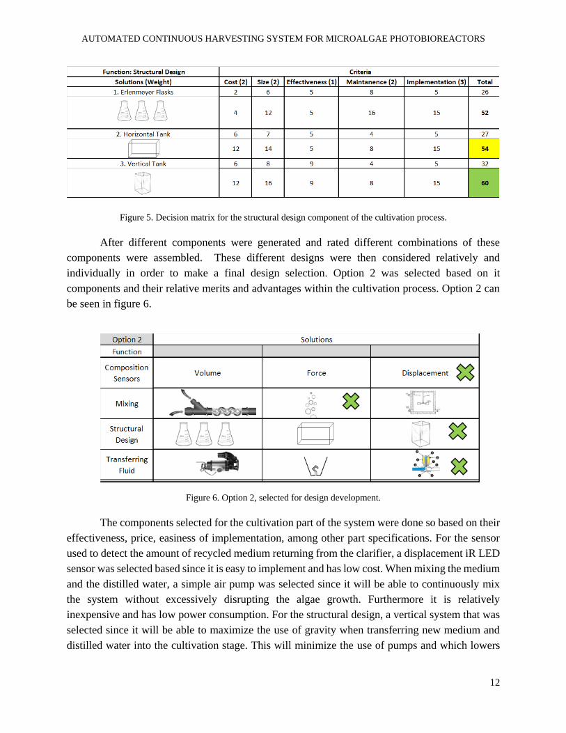
Figure 5. Decision matrix for the structural design component of the cultivation process.
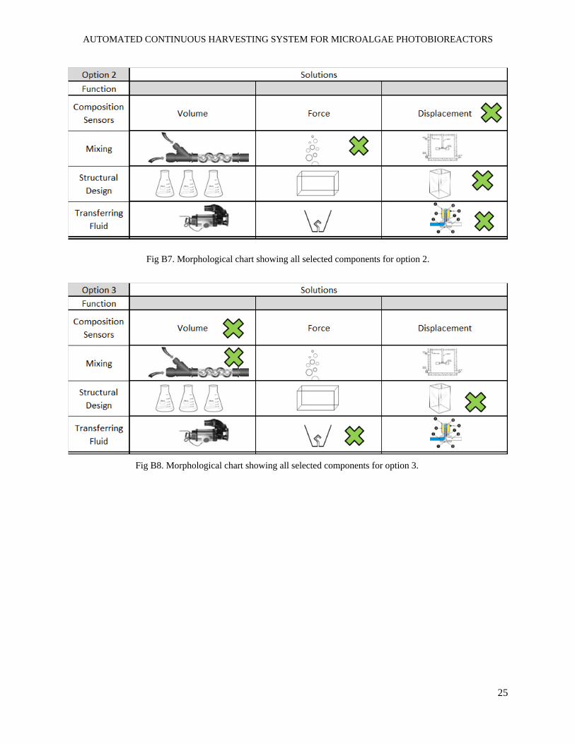
After different components were generated and rated different combinations of these
components were assembled. These different designs were then considered relatively and
individually in order to make a final design selection. Option 2 was selected based on it
components and their relative merits and advantages within the cultivation process. Option 2 can
be seen in figure 6.
Figure 6. Option 2, selected for design development.
The components selected for the cultivation part of the system were done so based on their
effectiveness, price, easiness of implementation, among other part specifications. For the sensor
used to detect the amount of recycled medium returning from the clarifier, a displacement iR LED
sensor was selected based since it is easy to implement and has low cost. When mixing the medium
and the distilled water, a simple air pump was selected since it will be able to continuously mix
the system without excessively disrupting the algae growth. Furthermore it is relatively
inexpensive and has low power consumption. For the structural design, a vertical system that was
selected since it will be able to maximize the use of gravity when transferring new medium and
distilled water into the cultivation stage. This will minimize the use of pumps and which lowers
AUTOMATED CONTINUOUS HARVESTING SYSTEM FOR MICROALGAE PHOTOBIOREACTORS
13
power consumption. In order to transfer the fluid between stages we selected a solenoid valve that
can be controlled with an Arduino microcontroller. This was selected based on the vertical
structure design and will allow the fluid to easily move through the pipes when the valve is open.
2. Harvesting Initiative
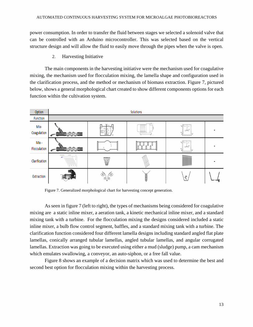
The main components in the harvesting initiative were the mechanism used for coagulative
mixing, the mechanism used for flocculation mixing, the lamella shape and configuration used in
the clarification process, and the method or mechanism of biomass extraction. Figure 7, pictured
below, shows a general morphological chart created to show different components options for each
function within the cultivation system.
Figure 7. Generalized morphological chart for harvesting concept generation.
As seen in figure 7 (left to right), the types of mechanisms being considered for coagulative
mixing are a static inline mixer, a aeration tank, a kinetic mechanical inline mixer, and a standard
mixing tank with a turbine. For the flocculation mixing the designs considered included a static
inline mixer, a bulb flow control segment, baffles, and a standard mixing tank with a turbine. The
clarification function considered four different lamella designs including standard angled flat plate
lamellas, conically arranged tubular lamellas, angled tubular lamellas, and angular corrugated
lamellas. Extraction was going to be executed using either a mud (sludge) pump, a cam mechanism
which emulates swallowing, a conveyor, an auto-siphon, or a free fall value.
Figure 8 shows an example of a decision matrix which was used to determine the best and
second best option for flocculation mixing within the harvesting process.
AUTOMATED CONTINUOUS HARVESTING SYSTEM FOR MICROALGAE PHOTOBIOREACTORS
14
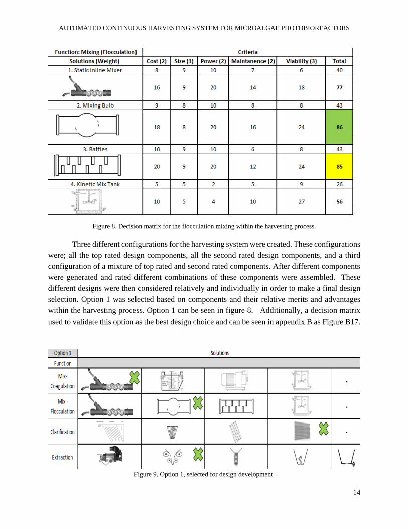
Figure 8. Decision matrix for the flocculation mixing within the harvesting process.
Three different configurations for the harvesting system were created. These configurations
were; all the top rated design components, all the second rated design components, and a third
configuration of a mixture of top rated and second rated components. After different components
were generated and rated different combinations of these components were assembled. These
different designs were then considered relatively and individually in order to make a final design
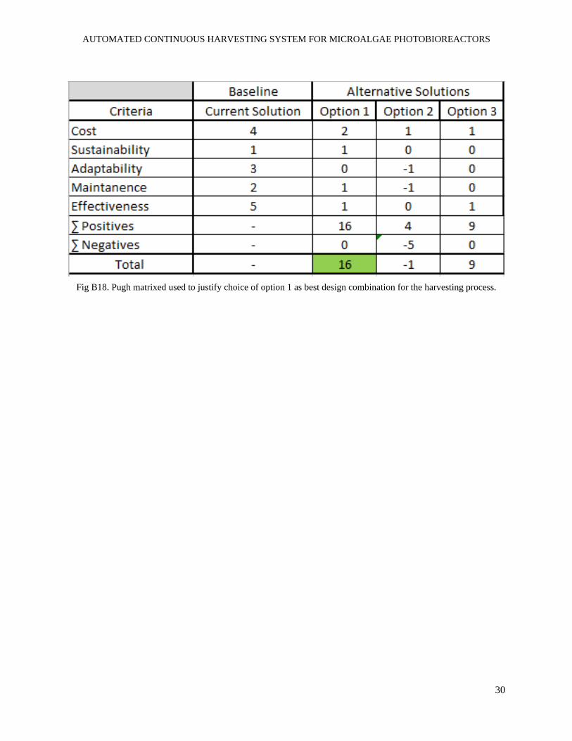
selection. Option 1 was selected based on components and their relative merits and advantages
within the harvesting process. Option 1 can be seen in figure 8. Additionally, a decision matrix
used to validate this option as the best design choice and can be seen in appendix B as Figure B17.
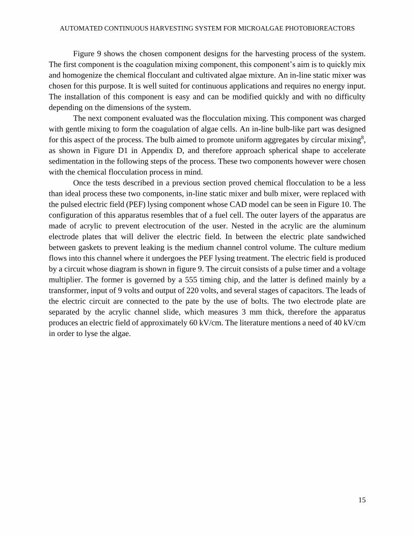
Figure 9. Option 1, selected for design development.
AUTOMATED CONTINUOUS HARVESTING SYSTEM FOR MICROALGAE PHOTOBIOREACTORS
15
Figure 9 shows the chosen component designs for the harvesting process of the system.
The first component is the coagulation mixing component, this component’s aim is to quickly mix
and homogenize the chemical flocculant and cultivated algae mixture. An in-line static mixer was
chosen for this purpose. It is well suited for continuous applications and requires no energy input.
The installation of this component is easy and can be modified quickly and with no difficulty
depending on the dimensions of the system.
The next component evaluated was the flocculation mixing. This component was charged
with gentle mixing to form the coagulation of algae cells. An in-line bulb-like part was designed
for this aspect of the process. The bulb aimed to promote uniform aggregates by circular mixing8,
as shown in Figure D1 in Appendix D, and therefore approach spherical shape to accelerate
sedimentation in the following steps of the process. These two components however were chosen
with the chemical flocculation process in mind.
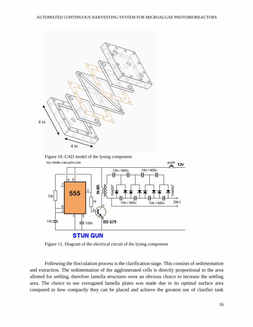
Once the tests described in a previous section proved chemical flocculation to be a less
than ideal process these two components, in-line static mixer and bulb mixer, were replaced with
the pulsed electric field (PEF) lysing component whose CAD model can be seen in Figure 10. The
configuration of this apparatus resembles that of a fuel cell. The outer layers of the apparatus are
made of acrylic to prevent electrocution of the user. Nested in the acrylic are the aluminum
electrode plates that will deliver the electric field. In between the electric plate sandwiched
between gaskets to prevent leaking is the medium channel control volume. The culture medium
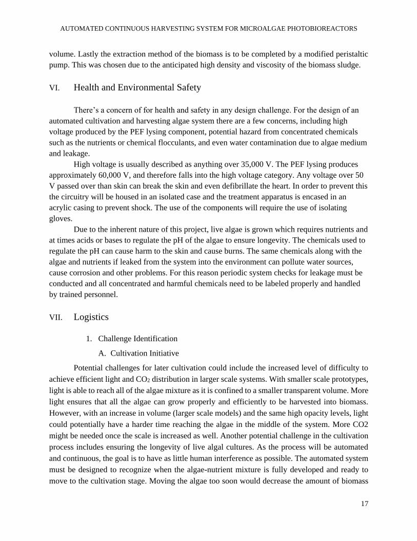
flows into this channel where it undergoes the PEF lysing treatment. The electric field is produced
by a circuit whose diagram is shown in figure 9. The circuit consists of a pulse timer and a voltage
multiplier. The former is governed by a 555 timing chip, and the latter is defined mainly by a
transformer, input of 9 volts and output of 220 volts, and several stages of capacitors. The leads of
the electric circuit are connected to the pate by the use of bolts. The two electrode plate are
separated by the acrylic channel slide, which measures 3 mm thick, therefore the apparatus
produces an electric field of approximately 60 kV/cm. The literature mentions a need of 40 kV/cm
in order to lyse the algae.
AUTOMATED CONTINUOUS HARVESTING SYSTEM FOR MICROALGAE PHOTOBIOREACTORS
16
Figure 10. CAD model of the lysing component
Figure 11. Diagram of the electrical circuit of the lysing component
Following the flocculation process is the clarification stage. This consists of sedimentation
and extraction. The sedimentation of the agglomerated cells is directly proportional to the area
allotted for settling, therefore lamella structures were an obvious choice to increase the settling
area. The choice to use corrugated lamella plates was made due to its optimal surface area
compared to how compactly they can be placed and achieve the greatest use of clarifier tank
4 in
4 in
AUTOMATED CONTINUOUS HARVESTING SYSTEM FOR MICROALGAE PHOTOBIOREACTORS
17
volume. Lastly the extraction method of the biomass is to be completed by a modified peristaltic
pump. This was chosen due to the anticipated high density and viscosity of the biomass sludge.
VI. Health and Environmental Safety
There’s a concern of for health and safety in any design challenge. For the design of an
automated cultivation and harvesting algae system there are a few concerns, including high
voltage produced by the PEF lysing component, potential hazard from concentrated chemicals
such as the nutrients or chemical flocculants, and even water contamination due to algae medium
and leakage.
High voltage is usually described as anything over 35,000 V. The PEF lysing produces
approximately 60,000 V, and therefore falls into the high voltage category. Any voltage over 50
V passed over than skin can break the skin and even defibrillate the heart. In order to prevent this
the circuitry will be housed in an isolated case and the treatment apparatus is encased in an
acrylic casing to prevent shock. The use of the components will require the use of isolating
gloves.
Due to the inherent nature of this project, live algae is grown which requires nutrients and
at times acids or bases to regulate the pH of the algae to ensure longevity. The chemicals used to
regulate the pH can cause harm to the skin and cause burns. The same chemicals along with the
algae and nutrients if leaked from the system into the environment can pollute water sources,
cause corrosion and other problems. For this reason periodic system checks for leakage must be
conducted and all concentrated and harmful chemicals need to be labeled properly and handled
by trained personnel.
VII. Logistics
1. Challenge Identification
A. Cultivation Initiative
Potential challenges for later cultivation could include the increased level of difficulty to
achieve efficient light and CO2 distribution in larger scale systems. With smaller scale prototypes,
light is able to reach all of the algae mixture as it is confined to a smaller transparent volume. More
light ensures that all the algae can grow properly and efficiently to be harvested into biomass.
However, with an increase in volume (larger scale models) and the same high opacity levels, light
could potentially have a harder time reaching the algae in the middle of the system. More CO2
might be needed once the scale is increased as well. Another potential challenge in the cultivation
process includes ensuring the longevity of live algal cultures. As the process will be automated
and continuous, the goal is to have as little human interference as possible. The automated system
must be designed to recognize when the algae-nutrient mixture is fully developed and ready to
move to the cultivation stage. Moving the algae too soon would decrease the amount of biomass
AUTOMATED CONTINUOUS HARVESTING SYSTEM FOR MICROALGAE PHOTOBIOREACTORS
18
produced, and moving it too late would result in the loss of live algae cultures. The system must
be designed with a way of detecting when the current mixture of algae has reached its peak growth.
The final challenge in the cultivation process of this system could be the recycling of clarified
medium. Since our group would like to reuse the water-nutrient medium again once the biomass
has been extracted from it, it is important that the proper amount of nutrients are added back into
the mixture so that it is strong enough to grow more algae, keeping the process continuous.
B. Harvesting Initiative
During the harvesting process of the system, many challenges upsurge. These include flow
rate control, flow regime control, and extraction of solid biomass. Using the standard chemical
means of flocculation the produced biomass still holds a lot of water and therefore needs to be
centrifuged and dehydrated using ovens before post-processing to achieve a final oil product that
will be converted to biodiesel. These added steps after flocculation and clarification have a large
added monetary and energy cost to the process and trying to omit these steps will prove difficult.
2. Risk Assessment
Because accidents often result from an unexpected reaction or event, potential risks that
could occur in this design project have been identified and certain procedures have been
developed in the hope of preventing or mitigating these risks. The first potential hazard found
could result from the breaking of materials when building the entire structure. Since the system
needs to be transparent in some areas to allow light to shine through, it would be best to use a
strong transparent plastic that will not break easily if dropped. Dropped materials could pose
potential harm to group members with sharp pieces and the spilt water medium. The biggest
potential risk that was identified in our design was the proximity of electronic controls and the
algae- water mixture. To ensure that no one or equipment is harmed through shocks, tests will be
run with low voltage in each design to ensure no water can reach the electronics before the
prototypes and design is tested fully. The last potential risk in this project included the potential
for submerged components to be corroded. To ensure that these submerged parts do not have to
be replaced, it is important to select a non-corrosive material before constructing the final design.
All of these measures can help to ensure that there is as little risks to equipment and group
members as possible when designing, constructing, and operating the automated harvesting
system. A Formal complete risk assessment can be seen in appendix E, which is included in the
hard copy of the report.
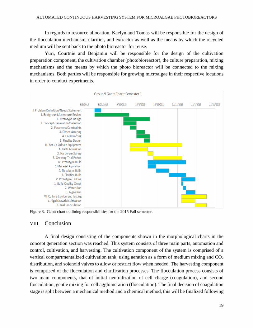
3. Schedule and Resource Allocation
A Gantt chart is provided in Figure 8 and outlines FSU based team work deadlines and
durations, UFPR based team work deadlines and durations, as well as mutually shared
responsibilities.
AUTOMATED CONTINUOUS HARVESTING SYSTEM FOR MICROALGAE PHOTOBIOREACTORS
19
In regards to resource allocation, Kaelyn and Tomas will be responsible for the design of
the flocculation mechanism, clarifier, and extractor as well as the means by which the recycled
medium will be sent back to the photo bioreactor for reuse.
Yuri, Courtnie and Benjamin will be responsible for the design of the cultivation
preparation component, the cultivation chamber (photobioreactor), the culture preparation, mixing
mechanisms and the means by which the photo bioreactor will be connected to the mixing
mechanisms. Both parties will be responsible for growing microalgae in their respective locations
in order to conduct experiments.
Figure 8. Gantt chart outlining responsibilities for the 2015 Fall semester.
VIII. Conclusion
A final design consisting of the components shown in the morphological charts in the
concept generation section was reached. This system consists of three main parts, automation and
control, cultivation, and harvesting. The cultivation component of the system is comprised of a
vertical compartmentalized cultivation tank, using aeration as a form of medium mixing and CO2
distribution, and solenoid valves to allow or restrict flow when needed. The harvesting component
is comprised of the flocculation and clarification processes. The flocculation process consists of
two main components, that of initial neutralization of cell charge (coagulation), and second
flocculation, gentle mixing for cell agglomeration (flocculation). The final decision of coagulation
stage is split between a mechanical method and a chemical method, this will be finalized following
AUTOMATED CONTINUOUS HARVESTING SYSTEM FOR MICROALGAE PHOTOBIOREACTORS
20
the necessary tests. The flocculation will be achieved using bulb like structures for gentle mixing.
Following the flocculation process is the clarification, this will consist of a lamella separator and
a peristaltic pump for extraction of biomass.
As the design develops many hurdles have had to be overcome and more continue to
appear. This causes the design of the system to be very dynamic. Currently the finalized
components of the system design are anticipated to meet the current requirements. Those
components not yet finalized are being tested to verify which will more efficiently meet those
requirements.
IX. Acknowledgements
Team 9 would like to thank the FIPSE-SEAP Program, as well as the partnership of Florida
State University and the Federal University of Paraná for making this senior design project
possible. We would like to extend our gratitude to Dr. Juan Ordonez, our sponsor; to Dr. José
Viriato Coelho Vargas, our UFPR mentor and coordinator of the Center for Research and
Development of Self-Sustainable Energy (NPDEAS); to André Bellin Mariano, the program
manager of NPDEAS and principal investigator for this project; and to Diego (INSERT LAST
NAME), a UFPR M. Sc. student, for his assistance with process automation.
X. References
[1] Yusuf, Christie. 2007. “Biodiesel from Microalgae”. Biotechnology Advances 25: 294 - 306.
Accessed 09/24/2015.
[2] G. Satyanarayana, A. B. Mariano, and J. V. C. Vargas. 2011. “A review on microalgae,
a versatile source for sustainable energy and materials”. International Journal of Energy
Research 35: 291–311. Accessed 09/24/2015.
[3] Ling Xu, Pamela J. Weathers, Xue-Rong Xiong, Chun-Zhao Liu. 2009. “Microalgal
bioreactors: Challenges and opportunities.” Engineering in Life Sciences 9,3:178-189.
Accessed 08/23/2015
[4] Dries Vandamme, Imogen Foubert, Koenraad Muylaert. 2013. “Flocculation as a low-cost
method for harvesting microalgae for bulk biomass production”. Trends in Biotechnology
31,4: 233–239. Accessed 09/24/2015.
[5] Sukenik A., Shelef G. 1984. “Algal autoflocculation--verification and proposed mechanism.”
Biotechnology and Bioengineering 26(2):142-147. Accessed 09/24/2015.
AUTOMATED CONTINUOUS HARVESTING SYSTEM FOR MICROALGAE PHOTOBIOREACTORS
21
[6] Zechen Wu, Yi Zhu, Weiya Huang, Chengwu Zhang, Tao Li, Yuanming Zhang, and Aifen
Li. 2012. “Evaluation of flocculation induced by pH increase for harvesting microalgae
and reuse of flocculated medium”. Biosource Technology 110: 496 - 502. Accessed
09/24/2015.
[7] Martina Goettel, Christian Eing, Christian Gusbeth, Ralf Straessner, Wolfgang Frey. 2013.
“Pulsed Electric field assisted extraction of intracellular valuables from microalgae”.
Algal Research (2).
[8] D.H. Fax, S.C. Traugott, G.F. Wislicenus. 1952. “Analysis of flow through a sphere”. Oak
Ridge National Laboratory (2).
XI. Appendices
A. Appendix A - Flocculation Time Test Results
Figure A1. Experimental Tanfloc sedimentation data.
AUTOMATED CONTINUOUS HARVESTING SYSTEM FOR MICROALGAE PHOTOBIOREACTORS
22
Figure A2. Experimental Chitosan sedimentation data.
B. Appendix B - Conception Generation and Selection Matrices
Cultivation Initiative
Figure B1. General morphological chart for all components being developed.
AUTOMATED CONTINUOUS HARVESTING SYSTEM FOR MICROALGAE PHOTOBIOREACTORS
23
Figure B2. Decision matrix for sensor used during cultivation process.
Figure B3. Decision matrix for mixing mechanism used during cultivation process.
Figure B4. Decision matrix for structural design used during cultivation process.
AUTOMATED CONTINUOUS HARVESTING SYSTEM FOR MICROALGAE PHOTOBIOREACTORS
24
Figure B5. Decision matrix for mechanism used to transfer fluids during cultivation process.
Fig B6. Morphological chart showing all selected components for option 1
AUTOMATED CONTINUOUS HARVESTING SYSTEM FOR MICROALGAE PHOTOBIOREACTORS
25
Fig B7. Morphological chart showing all selected components for option 2.
Fig B8. Morphological chart showing all selected components for option 3.
AUTOMATED CONTINUOUS HARVESTING SYSTEM FOR MICROALGAE PHOTOBIOREACTORS
26
________________________________________________________________________
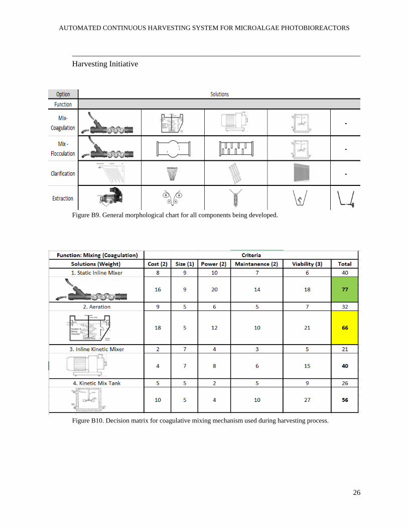
Harvesting Initiative
Figure B9. General morphological chart for all components being developed.
Figure B10. Decision matrix for coagulative mixing mechanism used during harvesting process.
AUTOMATED CONTINUOUS HARVESTING SYSTEM FOR MICROALGAE PHOTOBIOREACTORS
27
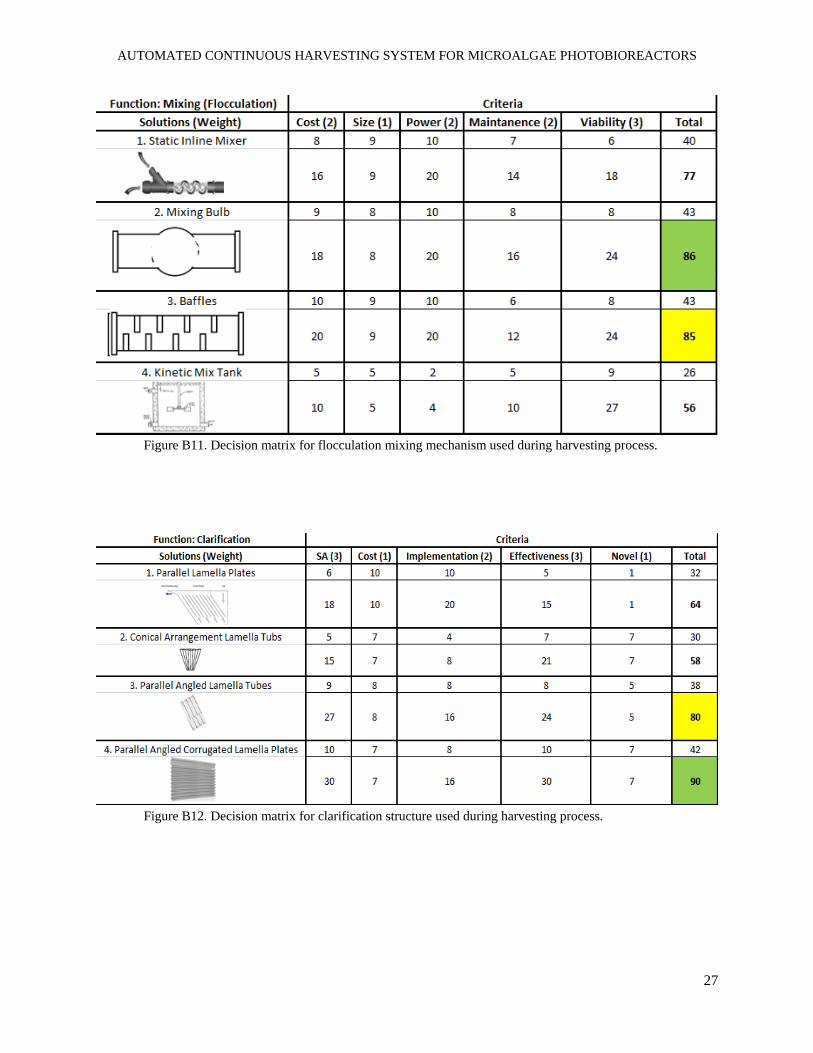
Figure B11. Decision matrix for flocculation mixing mechanism used during harvesting process.
Figure B12. Decision matrix for clarification structure used during harvesting process.
AUTOMATED CONTINUOUS HARVESTING SYSTEM FOR MICROALGAE PHOTOBIOREACTORS
28
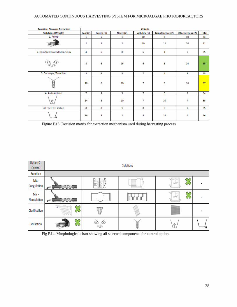
Figure B13. Decision matrix for extraction mechanism used during harvesting process.
Fig B14. Morphological chart showing all selected components for control option.
AUTOMATED CONTINUOUS HARVESTING SYSTEM FOR MICROALGAE PHOTOBIOREACTORS
29
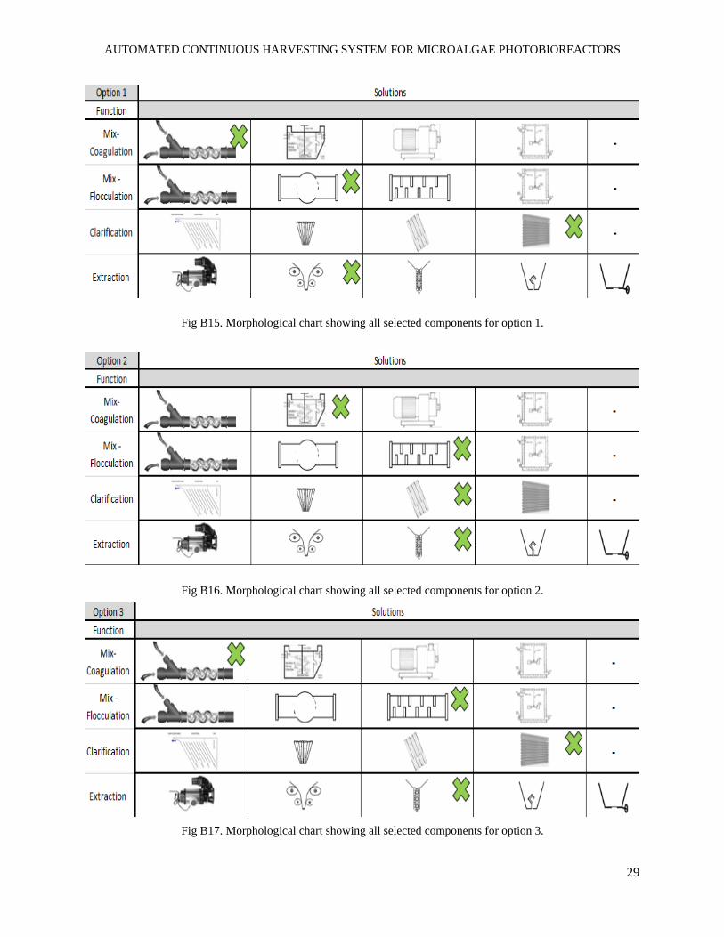
Fig B15. Morphological chart showing all selected components for option 1.
Fig B16. Morphological chart showing all selected components for option 2.
Fig B17. Morphological chart showing all selected components for option 3.
AUTOMATED CONTINUOUS HARVESTING SYSTEM FOR MICROALGAE PHOTOBIOREACTORS
30
Fig B18. Pugh matrixed used to justify choice of option 1 as best design combination for the harvesting process.
AUTOMATED CONTINUOUS HARVESTING SYSTEM FOR MICROALGAE PHOTOBIOREACTORS
31
C. Appendix C - CAD for Chosen Concept Designs
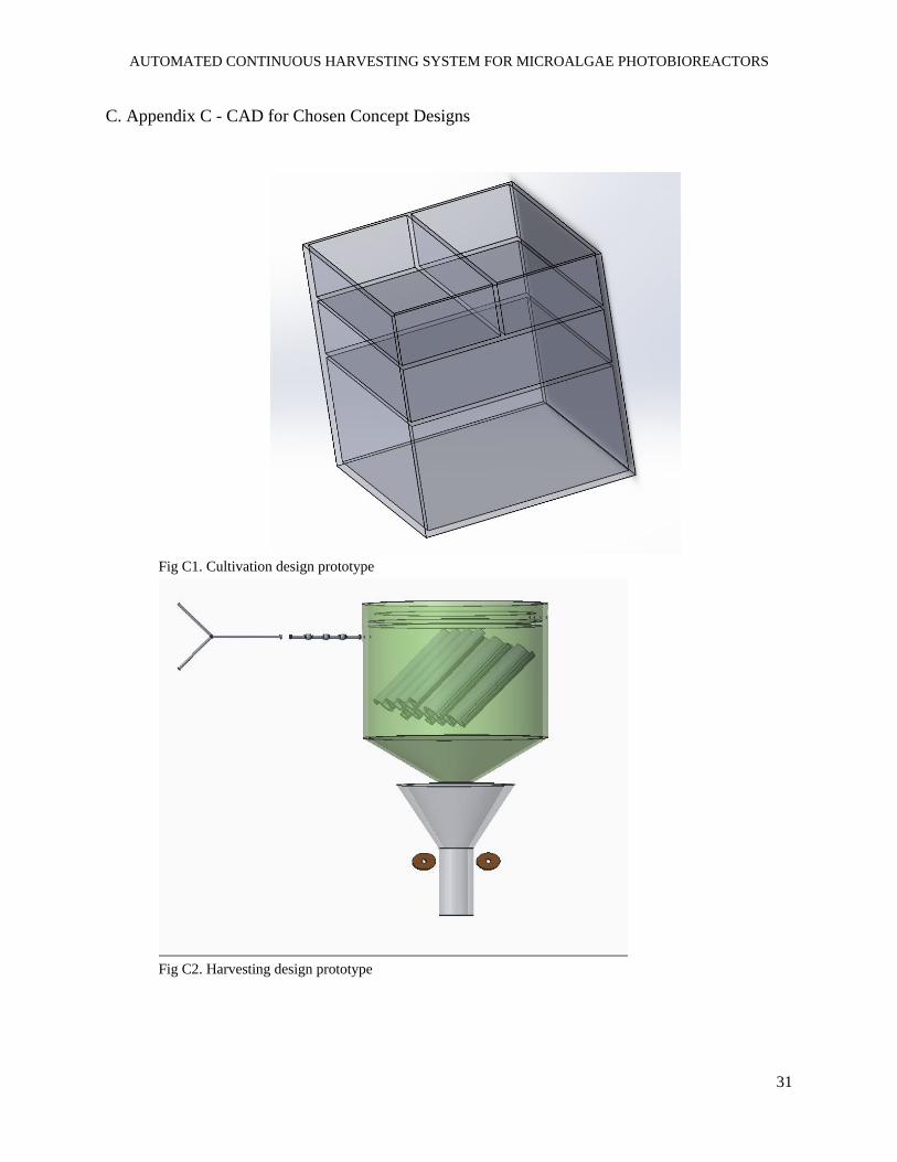
Fig C1. Cultivation design prototype
Fig C2. Harvesting design prototype
AUTOMATED CONTINUOUS HARVESTING SYSTEM FOR MICROALGAE PHOTOBIOREACTORS
32
.
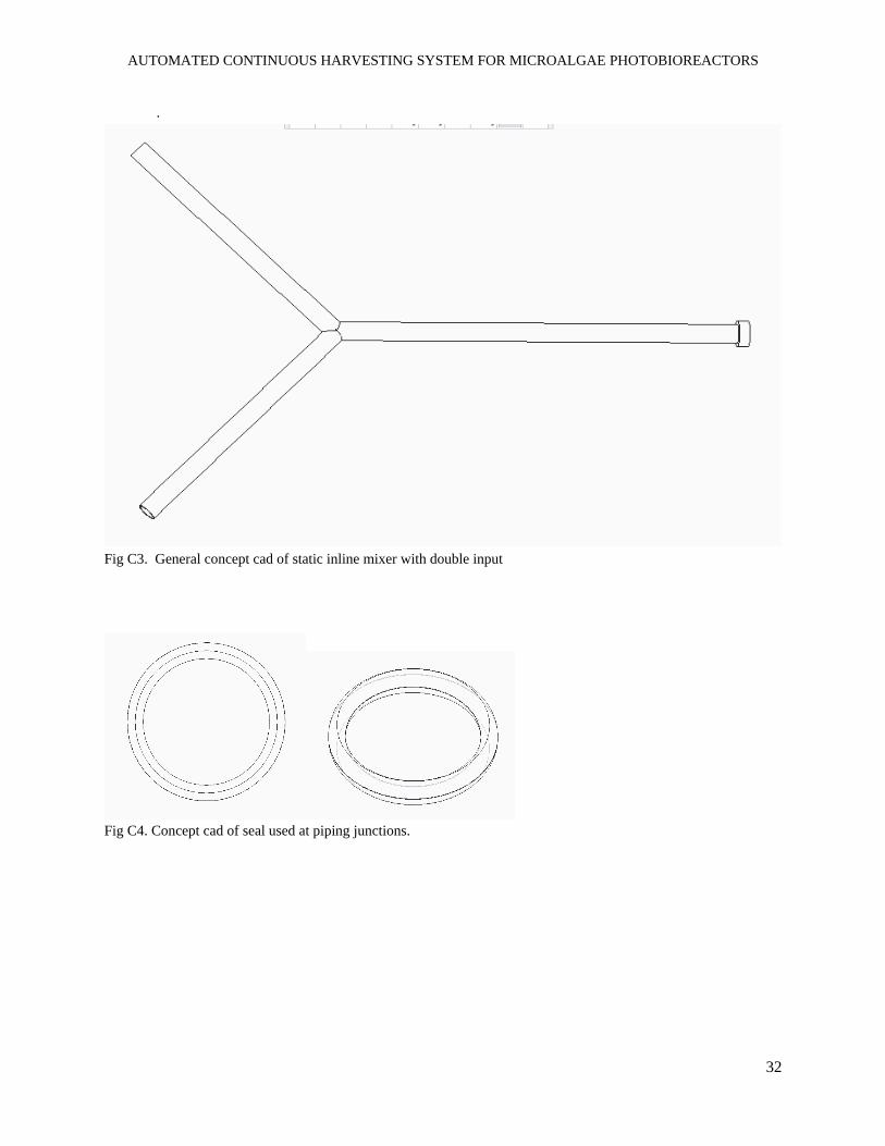
Fig C3. General concept cad of static inline mixer with double input
Fig C4. Concept cad of seal used at piping junctions.
AUTOMATED CONTINUOUS HARVESTING SYSTEM FOR MICROALGAE PHOTOBIOREACTORS
33
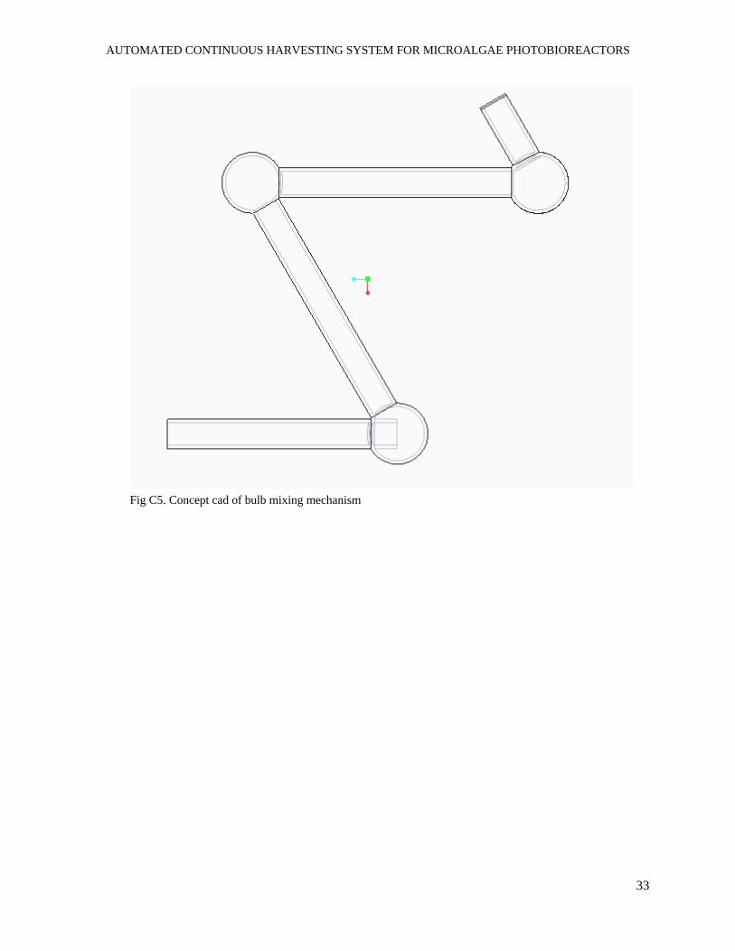
Fig C5. Concept cad of bulb mixing mechanism
AUTOMATED CONTINUOUS HARVESTING SYSTEM FOR MICROALGAE PHOTOBIOREACTORS
34
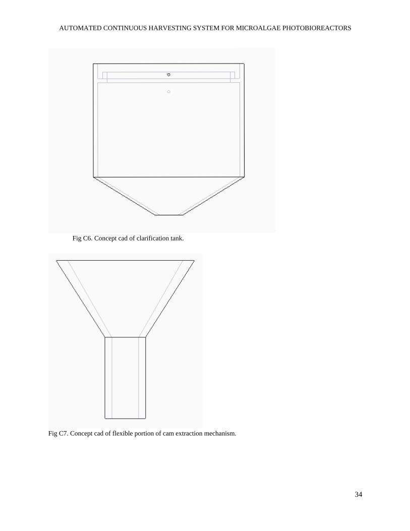
Fig C6. Concept cad of clarification tank.
Fig C7. Concept cad of flexible portion of cam extraction mechanism.
AUTOMATED CONTINUOUS HARVESTING SYSTEM FOR MICROALGAE PHOTOBIOREACTORS
35
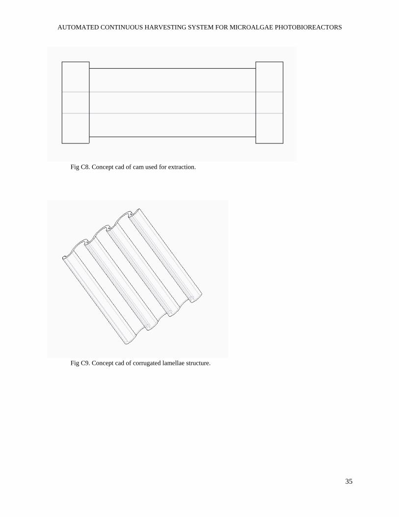
Fig C8. Concept cad of cam used for extraction.
Fig C9. Concept cad of corrugated lamellae structure.

AUTOMATED CONTINUOUS HARVESTING SYSTEM FOR MICROALGAE PHOTOBIOREACTORS
36
D. Appendix D - Additional Information
Figure D1. Flow regime within a sphere for the proof of concept of bulb mixing.