USING ANSA FOR AUTOMATED FE-MODELING OF TURBOCHARGER HOUSINGS · PDF fileUSING ANSA FOR...
6
4 th ANSA & μETA International Conference USING ANSA FOR AUTOMATED FE-MODELING OF TURBOCHARGER HOUSINGS 1 Dirk Dreissig * , 2 Dr. Frank Kruse 1 LASSO Ingenieurgesellschaft mbH, Germany, 2 BorgWarner Turbo Systems Engineering GmbH, Germany KEYWORDS – turbocharger, batch mesh, scripting, automation, ABAQUS ABSTRACT When dealing with models that exist in different variants and furthermore undergo several loadcases there is the strong demand for maximizing the level of automation in the process of creating the respective solver input files without loosing control about the process. The traditional, manual way of preparing the solver-ready FE model consists of the cleanup and defeaturing of the CAD geometry, followed by surface- and volume-meshing. Finally boundary conditions, loads, contacts and everything else, which makes up the loadcase, have to be set up. Exemplarily for turbocharger housings this complete FE model build up process has been automated by using ANSA's batch mesh and scripting capabilities – starting from the CAD geometry until the loadcase-dependent, ready to run ABAQUS solver input files, which are organized in a user-defined include structure. The process is controlled via an easy to use GUI, giving the user the possibility to control the level of automation and manually intervene at any point. TECHNICAL PAPER 1. MOTIVATION BorgWarner Turbo Systems develops and produces turbochargers for several types of engines of different OEMs. Therefore one has to deal with a large number of turbocharger housings, each of which is developed individually to fit best the required needs. The turbine housings undergo two analyses consisting of several load levels each: a heat transfer analysis and a thermo-mechanical analysis which uses the results of the heat transfer. The loads and boundary conditions for different housings are almost the same and differ only slightly in the values. In order to obtain fast results of plastification and stress distribution in turbine housing calculation in an early stage of product development a tool for the automatic model build up called “BWTS Batch Mesh” has been developed for ANSA. This reduces the modeling time, increases the reproducibility of the whole modeling process and reduces or even avoids modeling errors. By using this (semi-)automatic modeling procedure a complete simulation cycle – consisting of meshing, computation and results extraction – can be performed within less than a day. 2. “BWTS BATCH MESH” “BWTS Batch Mesh” makes use of ANSA's batch mesh and scripting capabilities and is designed as a modular process to cover the shell and volume meshing of turbocharger housings as well as the complete solver set-up for the mentioned analyses.
Transcript of USING ANSA FOR AUTOMATED FE-MODELING OF TURBOCHARGER HOUSINGS · PDF fileUSING ANSA FOR...
4th
ANSA & μETA International Conference
USING ANSA FOR AUTOMATED FE-MODELING OF TURBOCHARGER HOUSINGS 1Dirk Dreissig*, 2Dr. Frank Kruse 1LASSO Ingenieurgesellschaft mbH, Germany, 2BorgWarner Turbo Systems Engineering GmbH, Germany KEYWORDS – turbocharger, batch mesh, scripting, automation, ABAQUS ABSTRACT When dealing with models that exist in different variants and furthermore undergo several loadcases there is the strong demand for maximizing the level of automation in the process of creating the respective solver input files without loosing control about the process. The traditional, manual way of preparing the solver-ready FE model consists of the cleanup and defeaturing of the CAD geometry, followed by surface- and volume-meshing. Finally boundary conditions, loads, contacts and everything else, which makes up the loadcase, have to be set up. Exemplarily for turbocharger housings this complete FE model build up process has been automated by using ANSA's batch mesh and scripting capabilities – starting from the CAD geometry until the loadcase-dependent, ready to run ABAQUS solver input files, which are organized in a user-defined include structure. The process is controlled via an easy to use GUI, giving the user the possibility to control the level of automation and manually intervene at any point. TECHNICAL PAPER 1. MOTIVATION BorgWarner Turbo Systems develops and produces turbochargers for several types of engines of different OEMs. Therefore one has to deal with a large number of turbocharger housings, each of which is developed individually to fit best the required needs. The turbine housings undergo two analyses consisting of several load levels each: a heat transfer analysis and a thermo-mechanical analysis which uses the results of the heat transfer. The loads and boundary conditions for different housings are almost the same and differ only slightly in the values. In order to obtain fast results of plastification and stress distribution in turbine housing calculation in an early stage of product development a tool for the automatic model build up called “BWTS Batch Mesh” has been developed for ANSA. This reduces the modeling time, increases the reproducibility of the whole modeling process and reduces or even avoids modeling errors. By using this (semi-)automatic modeling procedure a complete simulation cycle – consisting of meshing, computation and results extraction – can be performed within less than a day. 2. “BWTS BATCH MESH” “BWTS Batch Mesh” makes use of ANSA's batch mesh and scripting capabilities and is designed as a modular process to cover the shell and volume meshing of turbocharger housings as well as the complete solver set-up for the mentioned analyses.
4th
ANSA & μETA International Conference
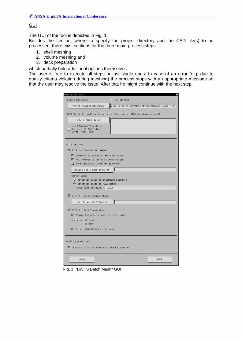
GUI The GUI of the tool is depicted in Fig. 1. Besides the section, where to specify the project directory and the CAD file(s) to be processed, there exist sections for the three main process steps:
1. shell meshing 2. volume meshing and 3. deck preparation
which partially hold additional options themselves. The user is free to execute all steps or just single ones. In case of an error (e.g. due to quality criteria violation during meshing) the process stops with an appropriate message so that the user may resolve the issue. After that he might continue with the next step.
Fig. 1: "BWTS Batch Mesh" GUI
4th
ANSA & μETA International Conference
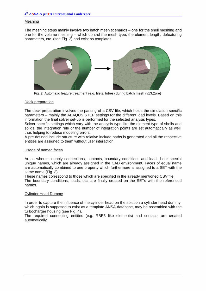
Meshing The meshing steps mainly involve two batch mesh scenarios – one for the shell meshing and one for the volume meshing – which control the mesh type, the element length, defeaturing parameters, etc. (see Fig. 2) and exist as templates.
Fig. 2: Automatic feature treatment (e.g. filets, tubes) during batch mesh (v13.2pre)
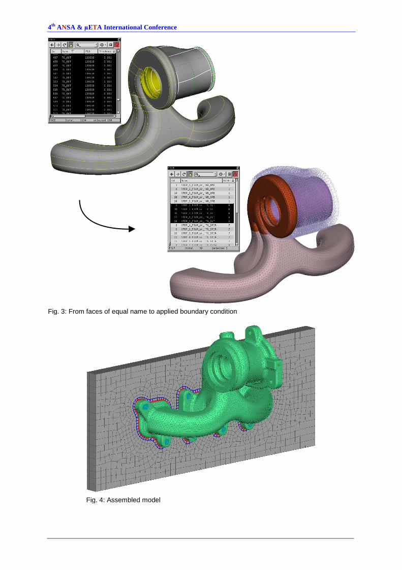
Deck preparation The deck preparation involves the parsing of a CSV file, which holds the simulation specific parameters – mainly the ABAQUS STEP settings for the different load levels. Based on this information the final solver set-up is performed for the selected analysis types. Solver specific settings which vary with the analysis type like the element type of shells and solids, the integration rule or the number of integration points are set automatically as well, thus helping to reduce modeling errors. A pre-defined include structure with relative include paths is generated and all the respective entities are assigned to them without user interaction. Usage of named faces Areas where to apply connections, contacts, boundary conditions and loads bear special unique names, which are already assigned in the CAD environment. Faces of equal name are automatically combined to one property which furthermore is assigned to a SET with the same name (Fig. 3). These names correspond to those which are specified in the already mentioned CSV file. The boundary conditions, loads, etc. are finally created on the SETs with the referenced names. Cylinder Head Dummy In order to capture the influence of the cylinder head on the solution a cylinder head dummy, which again is supposed to exist as a template ANSA-database, may be assembled with the turbocharger housing (see Fig. 4). The required connecting entities (e.g. RBE3 like elements) and contacts are created automatically.
4th
ANSA & μETA International Conference
Fig. 3: From faces of equal name to applied boundary condition
Fig. 4: Assembled model
4th
ANSA & μETA International Conference
3. COMPARISON OF THERMO-MECHANICAL ANALYSIS RESULTS FOR DIFFERENT MESHES Description of analysis cycle The load cycle covers several load levels which are represented by different ABAQUS STEP definitions in the structural analyses. A short CFD analysis in the beginning provides boundary conditions like heat transfer coefficients and transient fluid temperature for different regions of the model for the thermal analysis which in turn is the basis for the thermo-mechanical analysis. The thermal analysis additionally takes into account:
radiation and free convection to environment
heat flux between parts in contact
radiation between neighboring surfaces The thermo-mechanical considers:
the transient temperature distribution of the thermal analysis
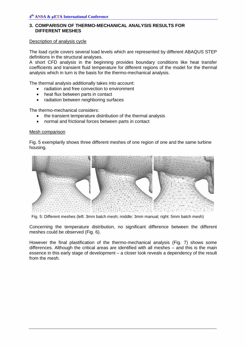
normal and frictional forces between parts in contact Mesh comparison Fig. 5 exemplarily shows three different meshes of one region of one and the same turbine housing.
Fig. 5: Different meshes (left: 3mm batch mesh; middle: 3mm manual; right: 5mm batch mesh)
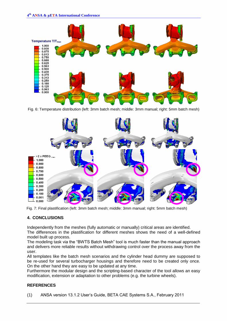
Concerning the temperature distribution, no significant difference between the different meshes could be observed (Fig. 6). However the final plastification of the thermo-mechanical analysis (Fig. 7) shows some differences. Although the critical areas are identified with all meshes – and this is the main essence in this early stage of development – a closer look reveals a dependency of the result from the mesh.
4th
ANSA & μETA International Conference
Fig. 6: Temperature distribution (left: 3mm batch mesh; middle: 3mm manual; right: 5mm batch mesh)
Fig. 7: Final plastification (left: 3mm batch mesh; middle: 3mm manual; right: 5mm batch mesh)
4. CONCLUSIONS Independently from the meshes (fully automatic or manually) critical areas are identified. The differences in the plastification for different meshes shows the need of a well-defined model built up process. The modeling task via the “BWTS Batch Mesh” tool is much faster than the manual approach and delivers more reliable results without withdrawing control over the process away from the user. All templates like the batch mesh scenarios and the cylinder head dummy are supposed to be re-used for several turbocharger housings and therefore need to be created only once. On the other hand they are easy to be updated at any time. Furthermore the modular design and the scripting-based character of the tool allows an easy modification, extension or adaptation to other problems (e.g. the turbine wheels). REFERENCES (1) ANSA version 13.1.2 User’s Guide, BETA CAE Systems S.A., February 2011
Temperature T/Tmax