Fading & OFDM Implementation Details - KU ITTCfrost/EECS_562/OFDM_for_56… · · 2017-04-19sec...
36
Fading & OFDM Implementation Details EECS 562 1
Transcript of Fading & OFDM Implementation Details - KU ITTCfrost/EECS_562/OFDM_for_56… · · 2017-04-19sec...
Fading & OFDM Implementation Details
EECS 562
1
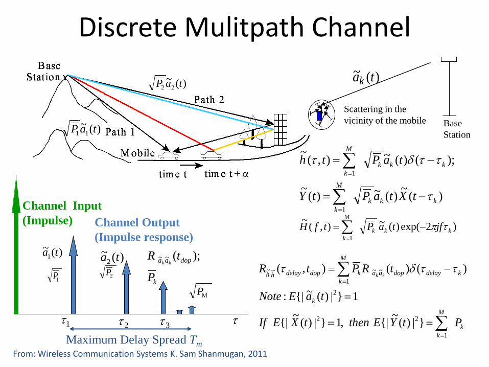
Discrete Mulitpath Channel
)(~11 taP
)(~ tak
Scattering in thevicinity of the mobile Base
Station
)(~22 taP
)(~)(~)(~
);()(~),(~
1
1
kkk
M
k
kkk
M
k
tXtaPtY
taPth
τ
ττδτ
−=
−=
∑
∑
=
=
)2exp()(~),(~1
kkk
M
kjftaPtfH τπ−=∑
=
k
M
k
k
kdelaydopaa
M
kkdopdelayhh
PtYEthentXEIf
taENote
tRPtRkk
∑
∑
=
=
==
=
−=
1
22
2
~~1
~~
}|)(~{|,1}|)(~{|
1}|)(~{|:
)()(),( ττδτ 2P
MP
)(~2 ta
1τ τ2τ 3τ
Channel Input (Impulse) Channel Output
(Impulse response)
Maximum Delay Spread Tm
1P
)(~1 ta
k
dopaa
P
tRkk
);(~~
From: Wireless Communication Systems K. Sam Shanmugan, 2011
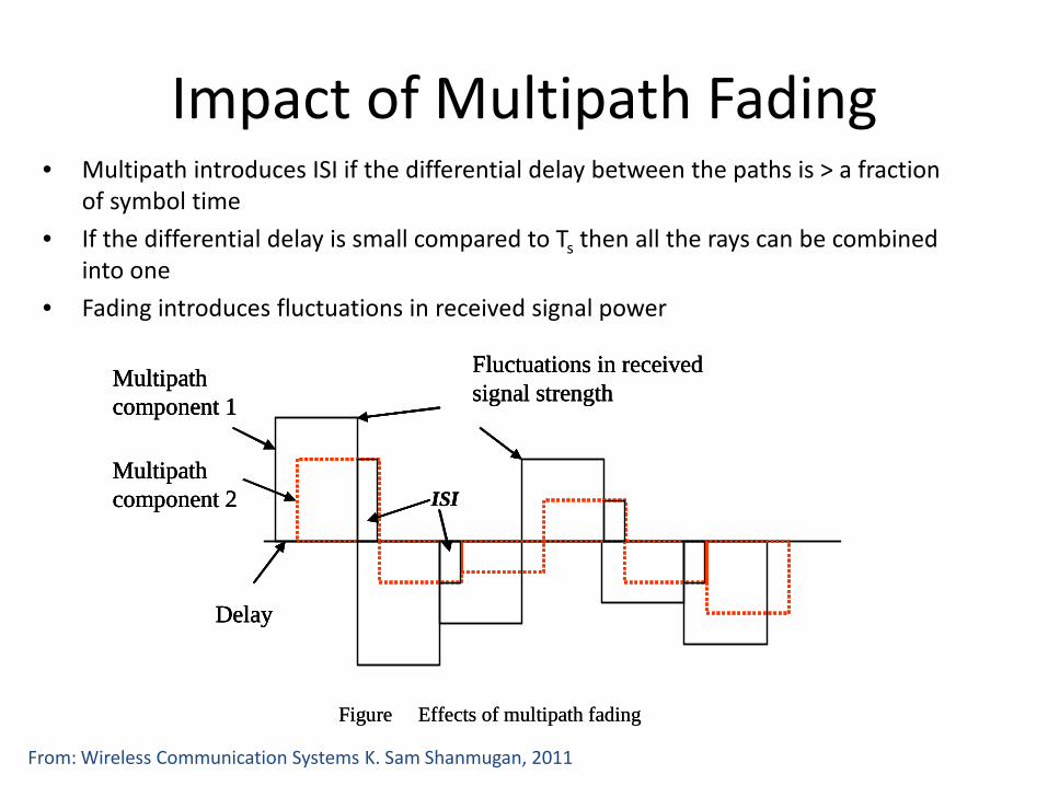
Impact of Multipath Fading• Multipath introduces ISI if the differential delay between the paths is > a fraction
of symbol time• If the differential delay is small compared to Ts then all the rays can be combined
into one• Fading introduces fluctuations in received signal power
Fluctuations in received signal strength
ISI
Multipathcomponent 1
Multipathcomponent 2
Delay
Figure Effects of multipath fading
Fluctuations in received signal strength
ISI
Multipathcomponent 1
Multipathcomponent 2
Delay
Fluctuations in received signal strength
ISI
Multipathcomponent 1
Multipathcomponent 2
Delay
Figure Effects of multipath fading
From: Wireless Communication Systems K. Sam Shanmugan, 2011
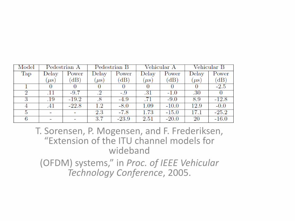
T. Sorensen, P. Mogensen, and F. Frederiksen, “Extension of the ITU channel models for
wideband(OFDM) systems,” in Proc. of IEEE Vehicular
Technology Conference, 2005.
5
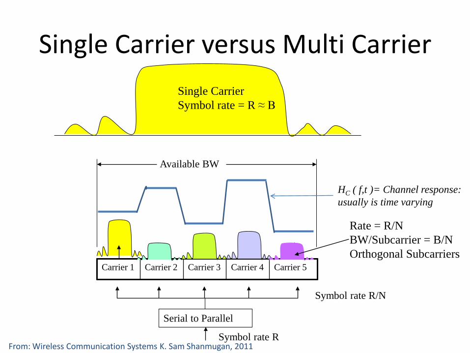
Single Carrier versus Multi Carrier
HC ( f,t )= Channel response: usually is time varying
Carrier 1 Carrier 2 Carrier 3 Carrier 4 Carrier 5
Available BW
Serial to Parallel
Symbol rate R
Symbol rate R/N
Single CarrierSymbol rate = R ≈ B
Rate = R/NBW/Subcarrier = B/NOrthogonal Subcarriers
From: Wireless Communication Systems K. Sam Shanmugan, 2011
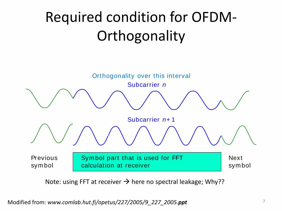
Required condition for OFDM-Orthogonality
Subcarrier n
Subcarrier n+1
Orthogonality over this interval
Previous symbol
Next symbol
Note: using FFT at receiver here no spectral leakage; Why??
Modified from: www.comlab.hut.fi/opetus/227/2005/9_227_2005.ppt
Symbol part that is used for FFT calculation at receiver
7
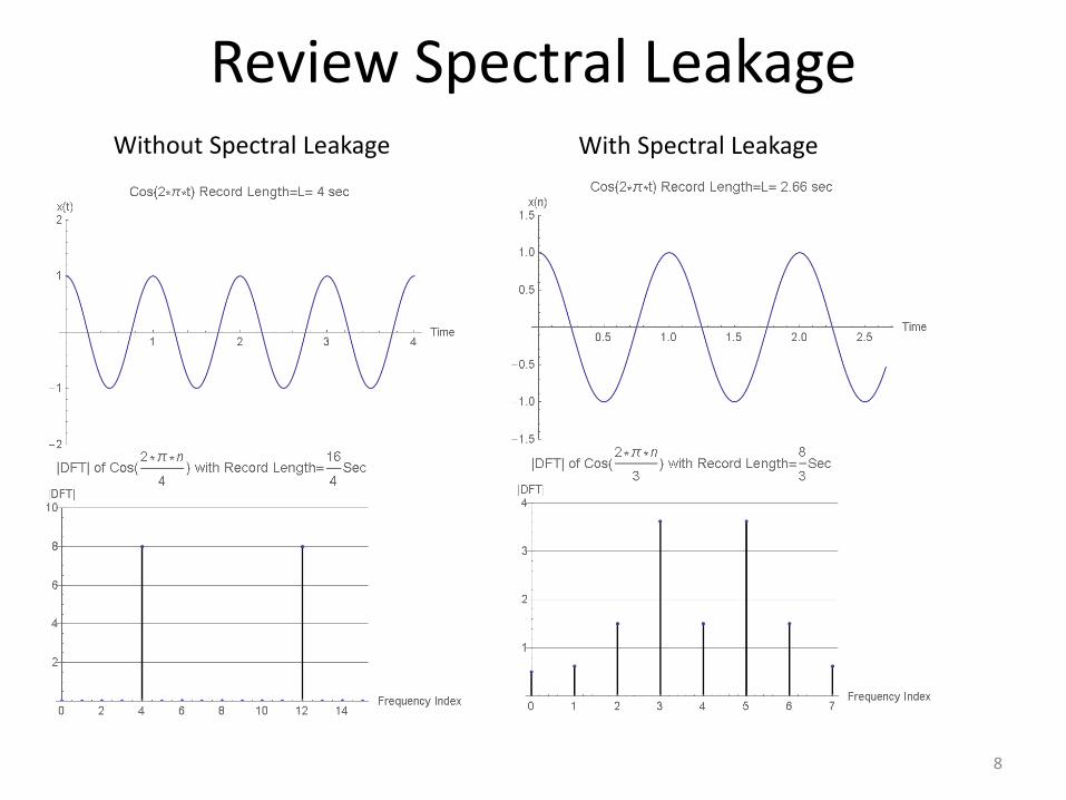
Review Spectral Leakage
8
Without Spectral Leakage With Spectral Leakage
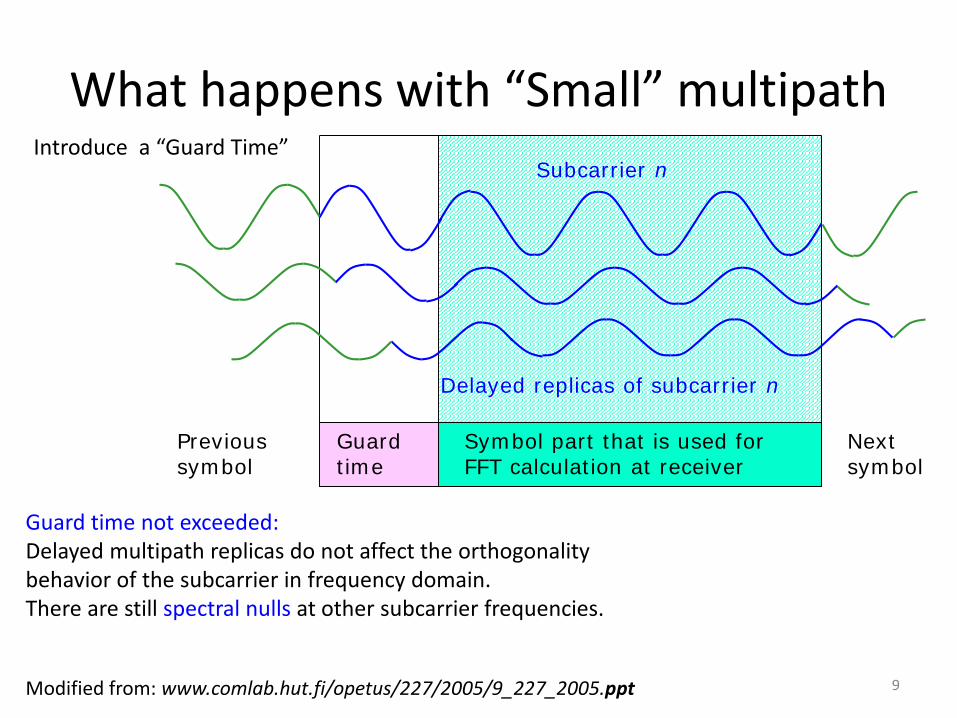
What happens with “Small” multipath
Guard time
Symbol part that is used for FFT calculation at receiver
Subcarrier n
Previous symbol
Next symbol
Delayed replicas of subcarrier n
Introduce a “Guard Time”
Guard time not exceeded:Delayed multipath replicas do not affect the orthogonality behavior of the subcarrier in frequency domain. There are still spectral nulls at other subcarrier frequencies.
Modified from: www.comlab.hut.fi/opetus/227/2005/9_227_2005.ppt 9
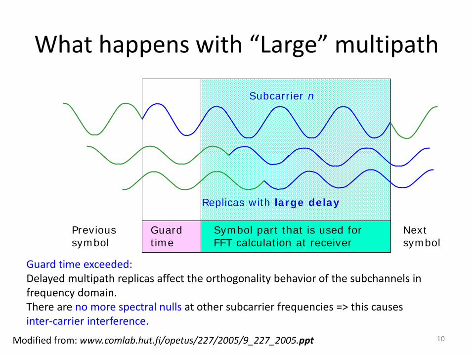
What happens with “Large” multipath
Modified from: www.comlab.hut.fi/opetus/227/2005/9_227_2005.ppt
Guard time
Symbol part that is used for FFT calculation at receiver
Subcarrier n
Previous symbol
Next symbol
Replicas with large delay
Guard time exceeded:Delayed multipath replicas affect the orthogonality behavior of the subchannels in frequency domain. There are no more spectral nulls at other subcarrier frequencies => this causes inter-carrier interference.
10
Modified from: www.comlab.hut.fi/opetus/227/2005/9_227_2005.ppt
Time
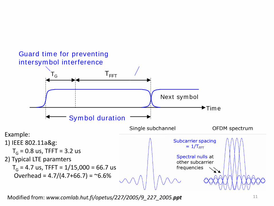
Guard time for preventing intersymbol interference
Symbol duration
Next symbol
TG TFFT
Example: 1) IEEE 802.11a&g:
TG = 0.8 us, TFFT = 3.2 us2) Typical LTE paramters
TG = 4.7 us, TFFT = 1/15,000 = 66.7 usOverhead = 4.7/(4.7+66.7) = ~6.6%
11
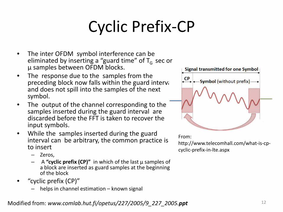
Cyclic Prefix-CP• The inter OFDM symbol interference can be
eliminated by inserting a “guard time” of TG sec or μ samples between OFDM blocks.
• The response due to the samples from the preceding block now falls within the guard interval and does not spill into the samples of the next symbol.
• The output of the channel corresponding to the samples inserted during the guard interval are discarded before the FFT is taken to recover the input symbols.
• While the samples inserted during the guard interval can be arbitrary, the common practice is to insert
– Zeros,– A “cyclic prefix (CP)” in which of the last μ samples of
a block are inserted as guard samples at the beginning of the block
• “cyclic prefix (CP)” – helps in channel estimation – known signal
12
From: http://www.telecomhall.com/what-is-cp-cyclic-prefix-in-lte.aspx
Modified from: www.comlab.hut.fi/opetus/227/2005/9_227_2005.ppt
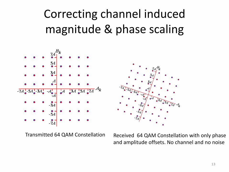
Correcting channel induced magnitude & phase scaling
Transmitted 64 QAM Constellation Received 64 QAM Constellation with only phase and amplitude offsets. No channel and no noise
13
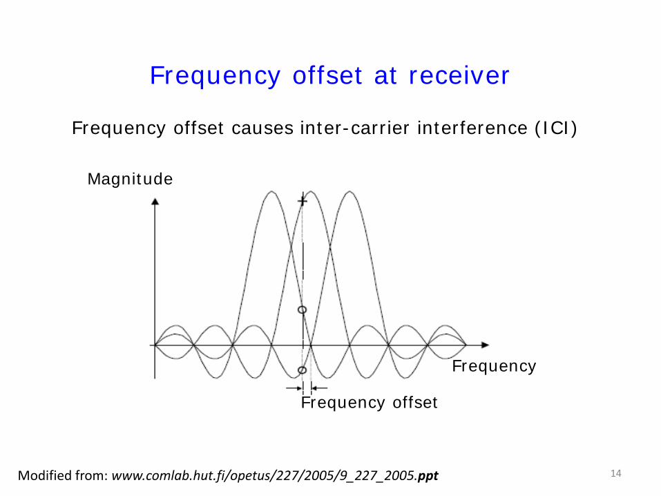
Frequency offset at receiver
Frequency offset causes inter-carrier interference (ICI)
Magnitude
Frequency
Frequency offset
Modified from: www.comlab.hut.fi/opetus/227/2005/9_227_2005.ppt 14
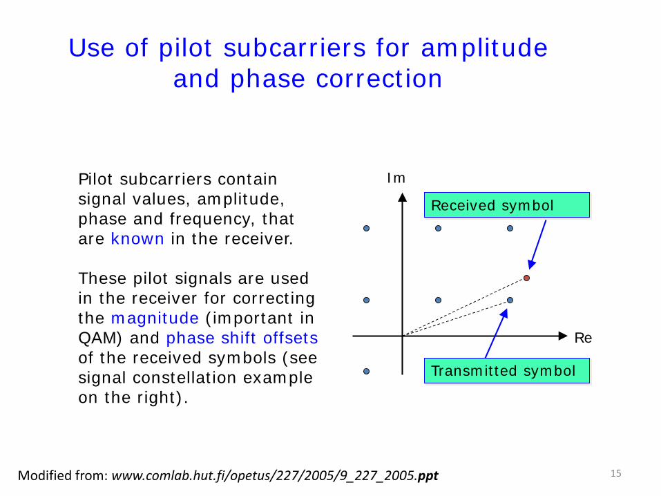
Use of pilot subcarriers for amplitude and phase correction
Pilot subcarriers contain signal values, amplitude, phase and frequency, that are known in the receiver.
These pilot signals are used in the receiver for correcting the magnitude (important in QAM) and phase shift offsetsof the received symbols (see signal constellation example on the right).
Re
Im
Received symbol
Transmitted symbol
Modified from: www.comlab.hut.fi/opetus/227/2005/9_227_2005.ppt 15
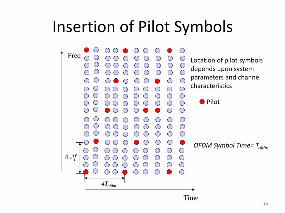
Insertion of Pilot Symbols Freq
4Tofdm
4 Δf
Time
Location of pilot symbols depends upon system parameters and channel characteristics
Pilot
16
OFDM Symbol Time= Tofdm
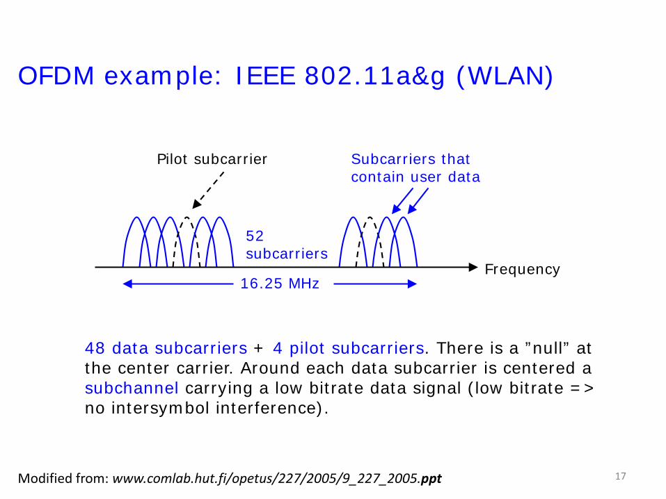
OFDM example: IEEE 802.11a&g (WLAN)
48 data subcarriers + 4 pilot subcarriers. There is a ”null” at the center carrier. Around each data subcarrier is centered a subchannel carrying a low bitrate data signal (low bitrate => no intersymbol interference).
52 subcarriers
Frequency16.25 MHz
Subcarriers that contain user data
Pilot subcarrier
Modified from: www.comlab.hut.fi/opetus/227/2005/9_227_2005.ppt 17
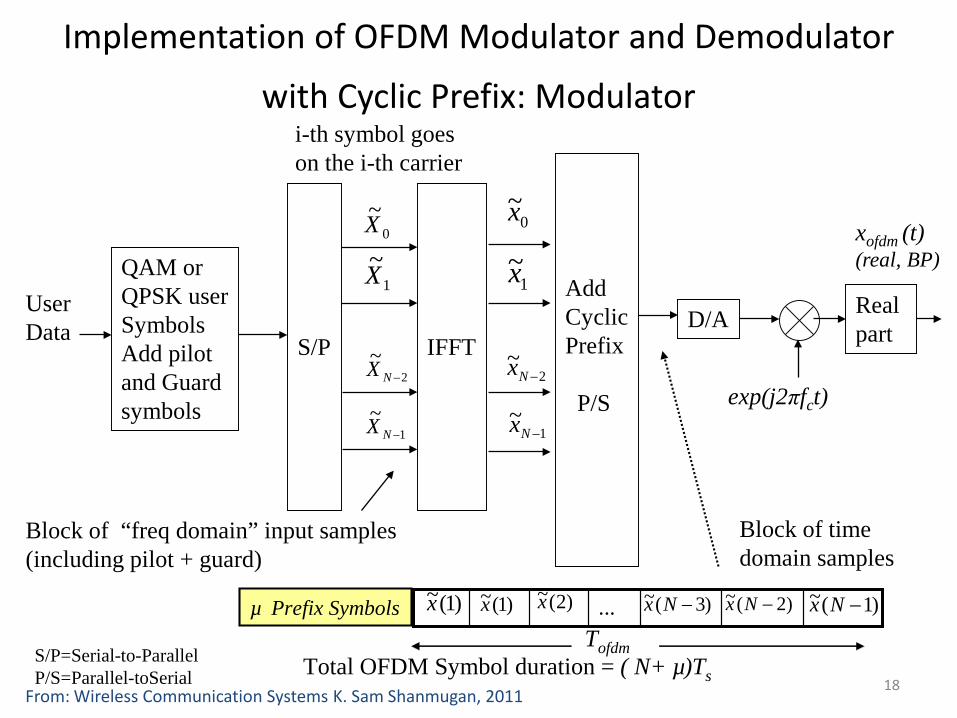
Implementation of OFDM Modulator and Demodulator
with Cyclic Prefix: Modulator
1~
−Nx
UserData
QAM or QPSK userSymbolsAdd pilotand Guardsymbols
S/P IFFT
AddCyclicPrefix
P/S
D/A
exp(j2πfct)
1~X
0~X
2~
−NX
1~
−NX
0~x
1~x
2~
−Nx
µ Prefix Symbols
Total OFDM Symbol duration = ( N+ µ)Ts
Tofdm
)2(~x)1(~x )3(~ −Nx )1(~ −Nx)2(~ −Nx...)1(~x
Real part
xofdm (t)(real, BP)
Block of “freq domain” input samples(including pilot + guard)
Block of timedomain samples
i-th symbol goes on the i-th carrier
S/P=Serial-to-ParallelP/S=Parallel-toSerial 18
From: Wireless Communication Systems K. Sam Shanmugan, 2011

Implementation of OFDM Modulator and Demodulator with Cyclic Prefix : Demodulator
EstimatedInput symbols
QAM or QPSKDemod
P/SFFT
RemoveCyclicPrefixS/P
Sample
Extract Pilot SymbolsEqualize 1/H(fk)
1~X
0~X
2~
−NX
1~
−NX
1~y
0~y
2~
−Ny
1~
−Ny
ComplexSignal
Discard the first μ SymbolsForward FFT; Divide by H(fi)
…)2(~X)1(~X)0(~X )3(~
−NX )1(~−NX)2(~
−NX
QuadratureDemodulator
fc
xofdm (t)(real, bandpass)
19From: Wireless Communication Systems K. Sam Shanmugan, 2011
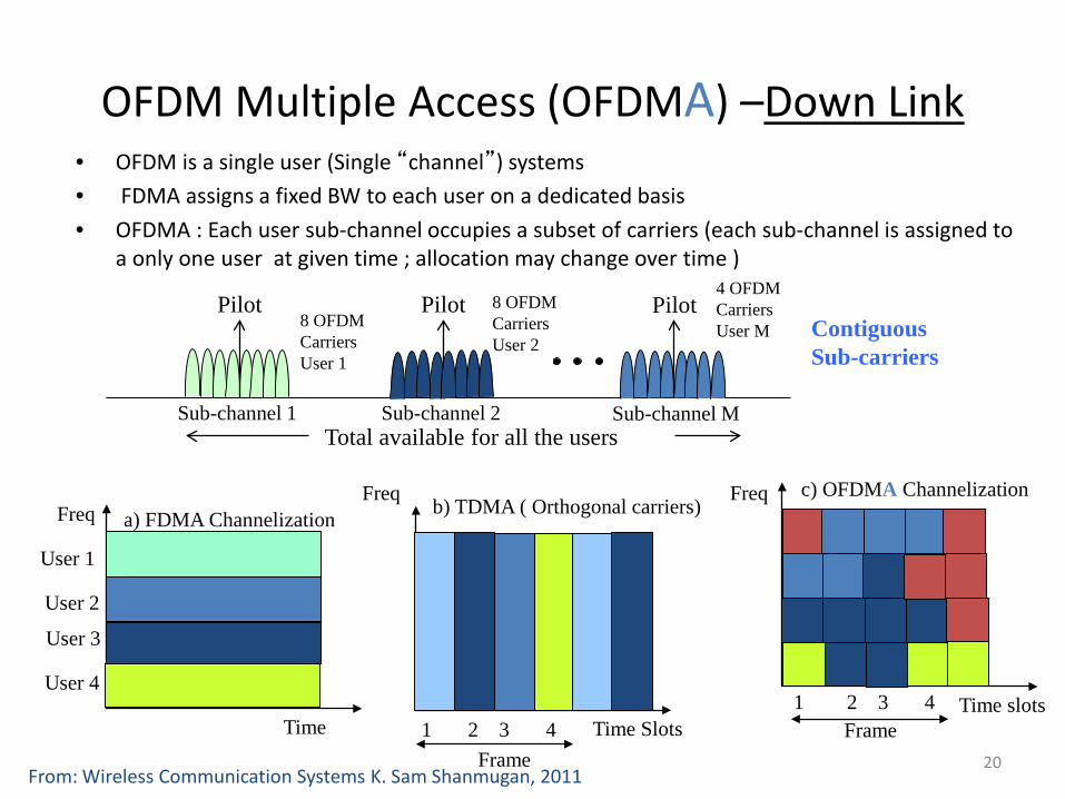
OFDM Multiple Access (OFDMA) –Down Link• OFDM is a single user (Single “channel”) systems• FDMA assigns a fixed BW to each user on a dedicated basis• OFDMA : Each user sub-channel occupies a subset of carriers (each sub-channel is assigned to
a only one user at given time ; allocation may change over time )
1 2 3 4 Time slots
Freq
Frame
c) OFDMA Channelization
User 4
User 2
User 3
User 1
Time
Freq a) FDMA ChannelizationFreq
Time Slots
b) TDMA ( Orthogonal carriers)
1 2 3 4Frame
Sub-channel 1
Pilot
Sub-channel M
Pilot
Sub-channel 2
Pilot8 OFDM CarriersUser 1
4 OFDM CarriersUser M
8 OFDM CarriersUser 2
Contiguous Sub-carriers
Total available for all the users
20From: Wireless Communication Systems K. Sam Shanmugan, 2011
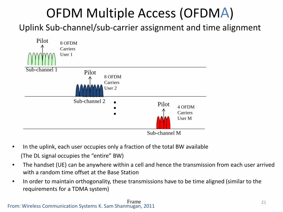
OFDM Multiple Access (OFDMA)Uplink Sub-channel/sub-carrier assignment and time alignment
Frame
Sub-channel 1
Pilot
Sub-channel 2
Pilot8 OFDM CarriersUser 2
4 OFDM CarriersUser M
8 OFDM CarriersUser 1
• In the uplink, each user occupies only a fraction of the total BW available(The DL signal occupies the “entire” BW)
• The handset (UE) can be anywhere within a cell and hence the transmission from each user arrived with a random time offset at the Base Station
• In order to maintain orthogonality, these transmissions have to be time aligned (similar to the requirements for a TDMA system)
Sub-channel M
Pilot
21From: Wireless Communication Systems K. Sam Shanmugan, 2011
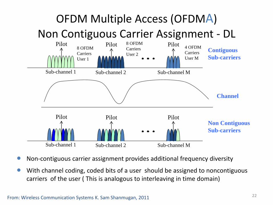
OFDM Multiple Access (OFDMA)Non Contiguous Carrier Assignment - DL
Sub-channel 1
Pilot
Sub-channel M
Pilot
Sub-channel 2
Pilot8 OFDM CarriersUser 1
4 OFDM CarriersUser M
8 OFDM CarriersUser 2
Contiguous Sub-carriers
Sub-channel 1
Pilot
Sub-channel M
Pilot
Sub-channel 2
PilotNon Contiguous Sub-carriers
Channel
Non-contiguous carrier assignment provides additional frequency diversity
With channel coding, coded bits of a user should be assigned to noncontiguous carriers of the user ( This is analogous to interleaving in time domain)
22From: Wireless Communication Systems K. Sam Shanmugan, 2011
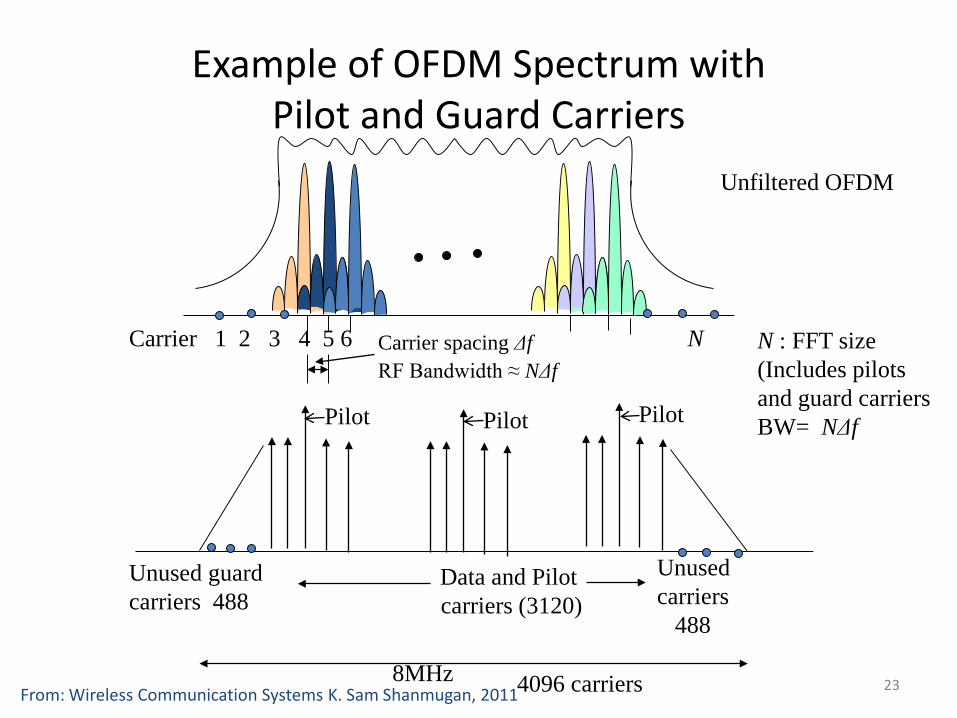
Example of OFDM Spectrum with Pilot and Guard Carriers
Carrier 1 2 3 4 5 6 N
Pilot Pilot Pilot
Unused guardcarriers 488
Unusedcarriers
488
Data and Pilot carriers (3120)
8MHz
Unfiltered OFDM
Carrier spacing ΔfRF Bandwidth ≈ NΔf
4096 carriers
N : FFT size(Includes pilots and guard carriersBW= NΔf
23From: Wireless Communication Systems K. Sam Shanmugan, 2011
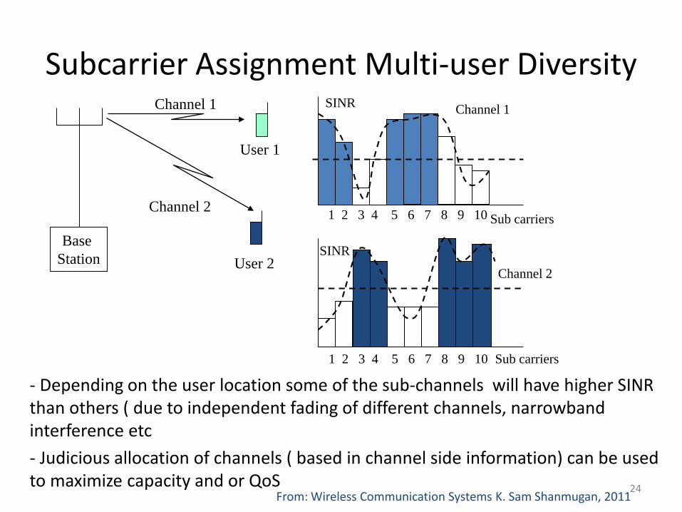
Subcarrier Assignment Multi-user Diversity
- Depending on the user location some of the sub-channels will have higher SINR than others ( due to independent fading of different channels, narrowband interference etc- Judicious allocation of channels ( based in channel side information) can be used to maximize capacity and or QoS
Base Station
Channel 1
Channel 2
User 2
User 1
SINR
Sub carriers
SINR
Channel 1
Channel 2
Sub carriers
1 2 3 4 5 6 7 8 9 10
1 2 3 4 5 6 7 8 9 10
24From: Wireless Communication Systems K. Sam Shanmugan, 2011
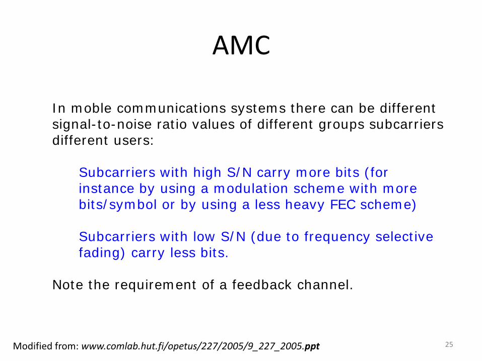
AMC
In moble communications systems there can be different signal-to-noise ratio values of different groups subcarriers different users:
Note the requirement of a feedback channel.
Subcarriers with high S/N carry more bits (for instance by using a modulation scheme with more bits/symbol or by using a less heavy FEC scheme)
Subcarriers with low S/N (due to frequency selective fading) carry less bits.
Modified from: www.comlab.hut.fi/opetus/227/2005/9_227_2005.ppt 25
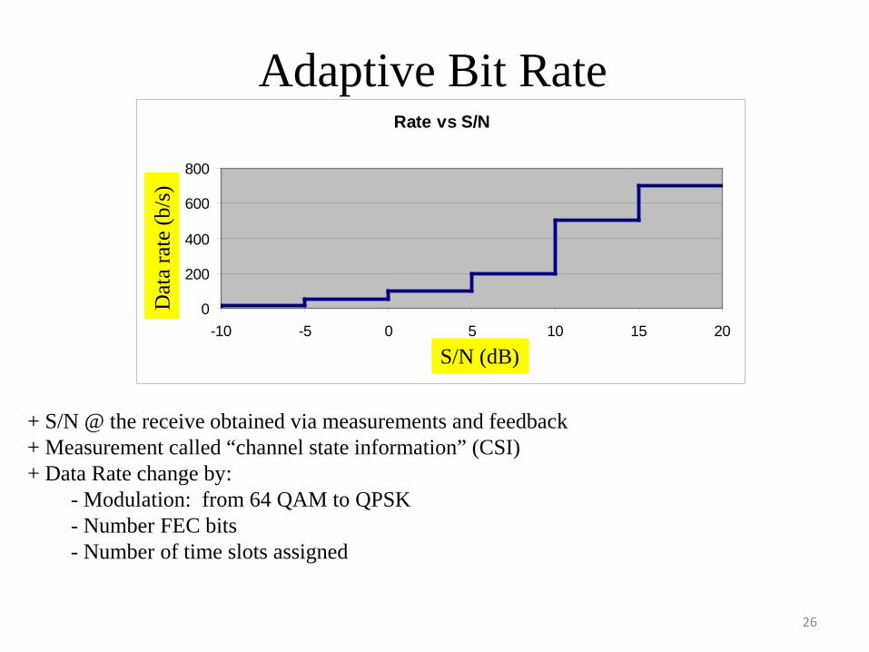
Adaptive Bit RateRate vs S/N
0
200
400
600
800
-10 -5 0 5 10 15 20
S/N (dB)
Date
Rat
e (k
b
+ S/N @ the receive obtained via measurements and feedback+ Measurement called “channel state information” (CSI)+ Data Rate change by:
- Modulation: from 64 QAM to QPSK- Number FEC bits- Number of time slots assigned
Dat
a ra
te (b
/s)
S/N (dB)
26
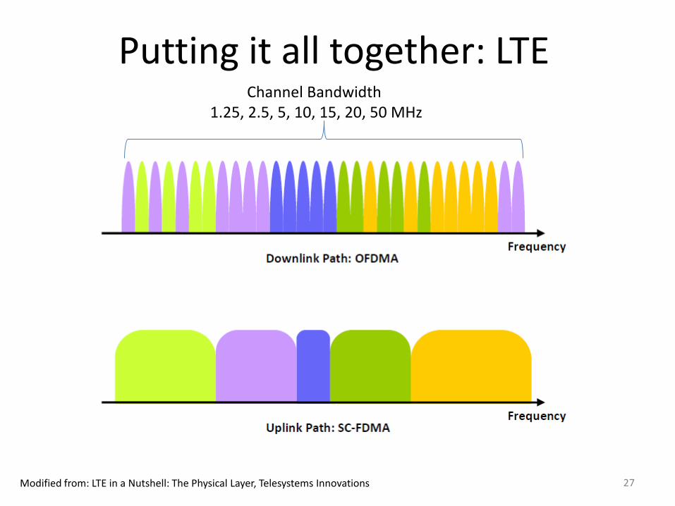
Putting it all together: LTE
Modified from: LTE in a Nutshell: The Physical Layer, Telesystems Innovations
Channel Bandwidth 1.25, 2.5, 5, 10, 15, 20, 50 MHz
27
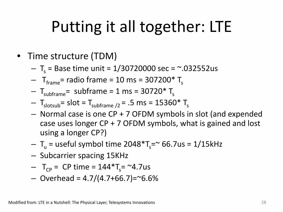
Putting it all together: LTE• Time structure (TDM)
– Ts = Base time unit = 1/30720000 sec = ~.032552us– Tframe= radio frame = 10 ms = 307200* Ts
– Tsubframe= subframe = 1 ms = 30720* Ts
– Tslotsub= slot = Tsubframe /2 = .5 ms = 15360* Ts
– Normal case is one CP + 7 OFDM symbols in slot (and expended case uses longer CP + 7 OFDM symbols, what is gained and lost using a longer CP?)
– Tu = useful symbol time 2048*Ts=~ 66.7us = 1/15kHz– Subcarrier spacing 15KHz– TCP = CP time = 144*Ts= ~4.7us– Overhead = 4.7/(4.7+66.7)=~6.6%
Modified from: LTE in a Nutshell: The Physical Layer, Telesystems Innovations 28
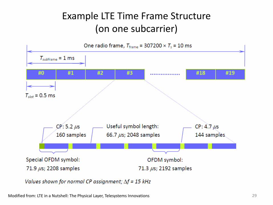
Example LTE Time Frame Structure(on one subcarrier)
Modified from: LTE in a Nutshell: The Physical Layer, Telesystems Innovations 29
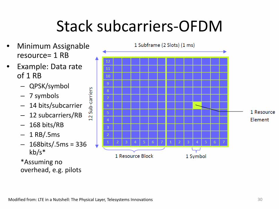
Stack subcarriers-OFDM
Modified from: LTE in a Nutshell: The Physical Layer, Telesystems Innovations
• Minimum Assignable resource= 1 RB
• Example: Data rate of 1 RB– QPSK/symbol– 7 symbols– 14 bits/subcarrier– 12 subcarriers/RB– 168 bits/RB– 1 RB/.5ms– 168bits/.5ms = 336
kb/s**Assuming no overhead, e.g. pilots
30
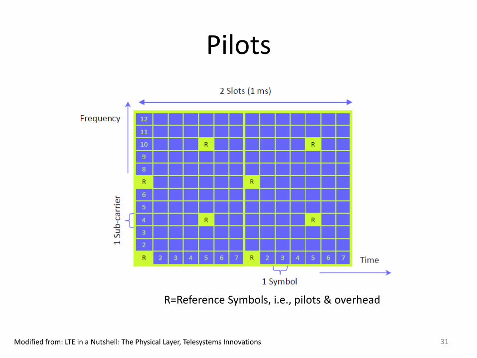
Pilots
Modified from: LTE in a Nutshell: The Physical Layer, Telesystems Innovations
R=Reference Symbols, i.e., pilots & overhead
31
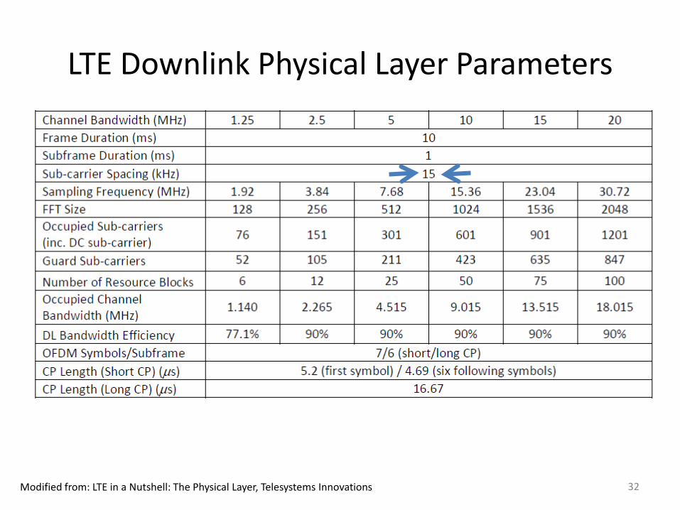
LTE Downlink Physical Layer Parameters
Modified from: LTE in a Nutshell: The Physical Layer, Telesystems Innovations 32
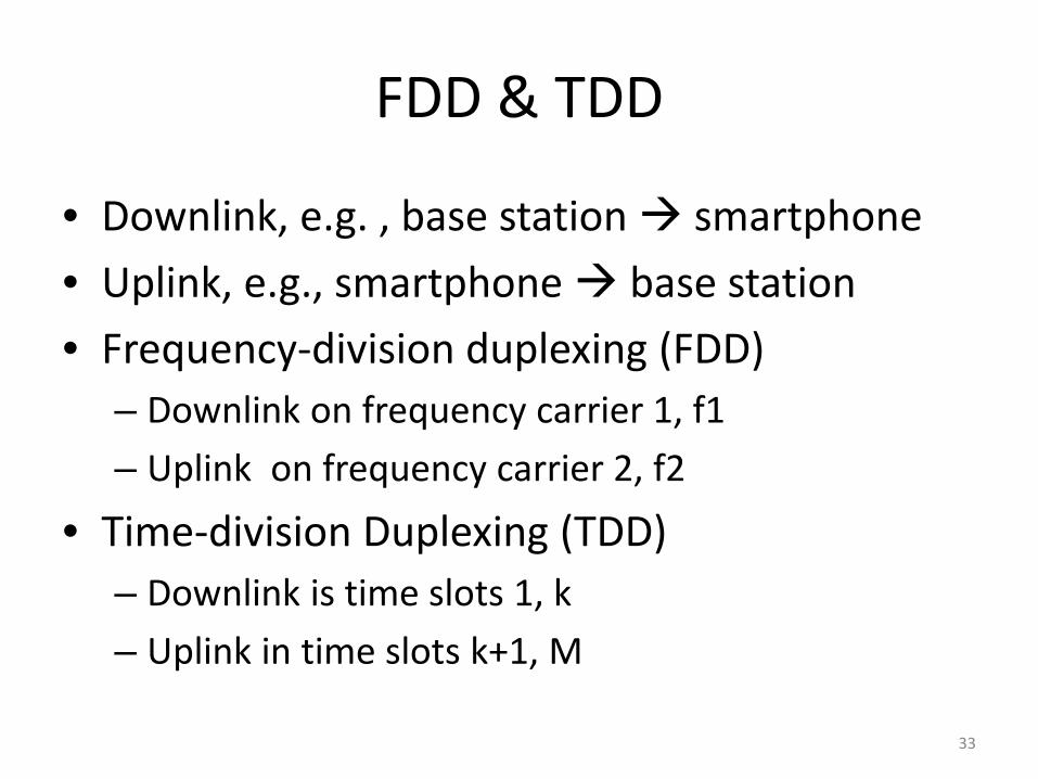
FDD & TDD
• Downlink, e.g. , base station smartphone • Uplink, e.g., smartphone base station• Frequency-division duplexing (FDD)
– Downlink on frequency carrier 1, f1– Uplink on frequency carrier 2, f2
• Time-division Duplexing (TDD)– Downlink is time slots 1, k– Uplink in time slots k+1, M
33
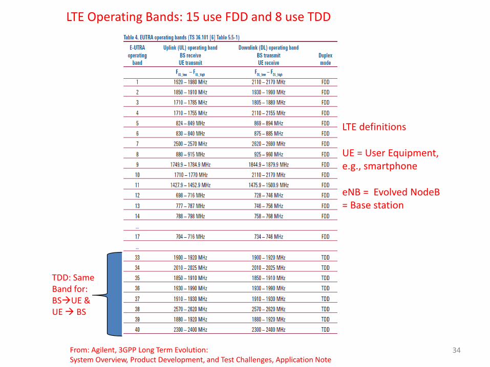
From: Agilent, 3GPP Long Term Evolution:System Overview, Product Development, and Test Challenges, Application Note
LTE Operating Bands: 15 use FDD and 8 use TDD
TDD: Same Band for:BSUE & UE BS
LTE definitions
UE = User Equipment, e.g., smartphone
eNB = Evolved NodeB= Base station
34
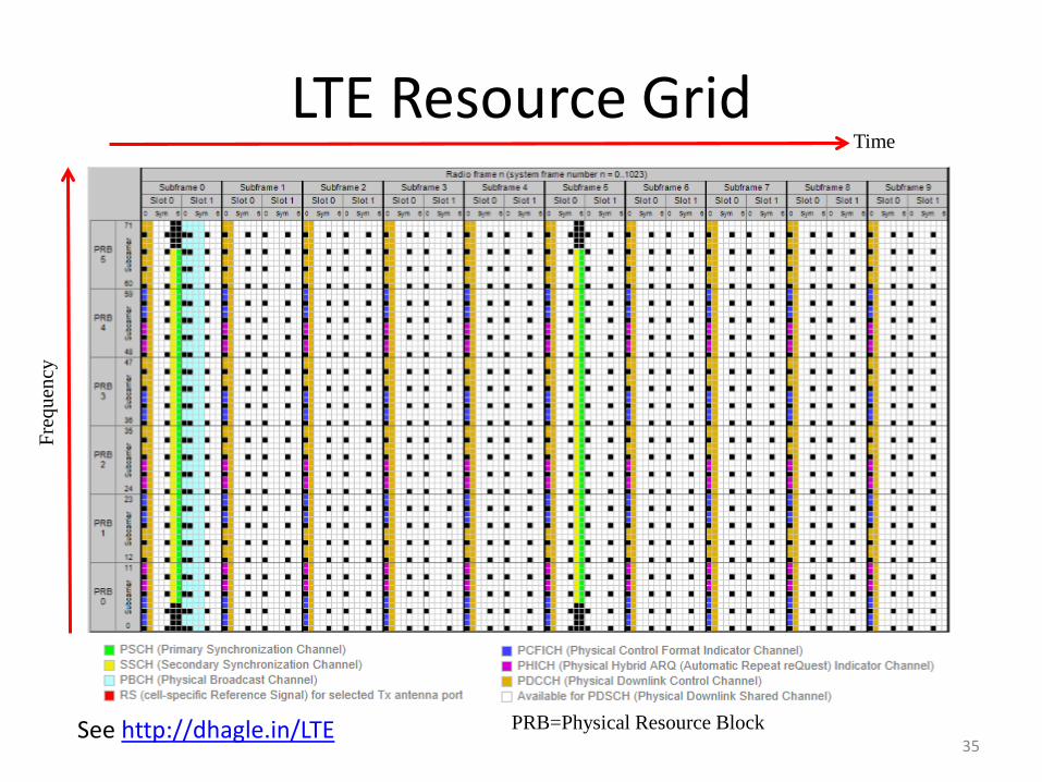
LTE Resource Grid
See http://dhagle.in/LTE PRB=Physical Resource Block
Time
Freq
uenc
y
35
Uplink: SC-FDMA• SC-FDMA= single carrier FDMA
– aka DFT spread OFDM (DFTS-OFDM) • SC-FDMA closely related to OFDM• When multiple carriers with arbitrary phases are
added together, we no longer have a constant envelope signal, resulting in high Peak-to-Average Power Ratio (PAR)
• Power efficient RF amplifiers need constant envelope signal
• OFDM has high Peak-to-Average Power Ratio (PAR) is bad for power efficient transmission needed for UE’s.
36


![arXiv:1203.3871v1 [math.AP] 17 Mar 2012 · ε) and the preceding compactness method is out of use. To overcome this difficulty, Ukai [27] used the dispersive effects generated by](https://static.fdocument.org/doc/165x107/5cdc112488c99373238b5421/arxiv12033871v1-mathap-17-mar-2012-and-the-preceding-compactness-method.jpg)
![InertSustain AQ-C18 English Brochure.ppt [互換モード] · 2019-11-29 · It is indeed difficult to retain highly polar samples by reversed phase mode as the polar samples tend](https://static.fdocument.org/doc/165x107/5f5a12a6ce8b5012d70501a9/inertsustain-aq-c18-english-fff-2019-11-29-it-is-indeed-difficult.jpg)