Experiment 11 - National Tsing Hua Universityedl.pme.nthu.edu.tw/newweb/tw/Old/courses/Machine...
33
Experiment 11 Gearing
Transcript of Experiment 11 - National Tsing Hua Universityedl.pme.nthu.edu.tw/newweb/tw/Old/courses/Machine...
Experiment 11
Gearing
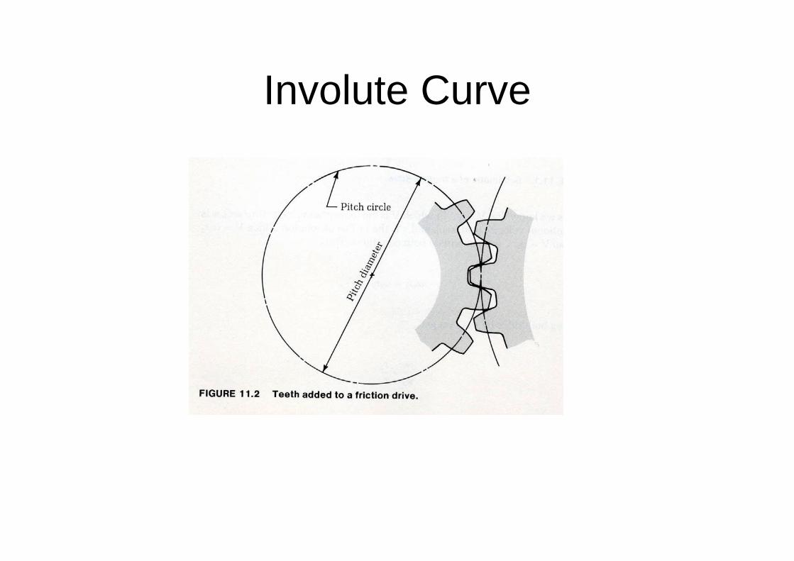
Involute Curve
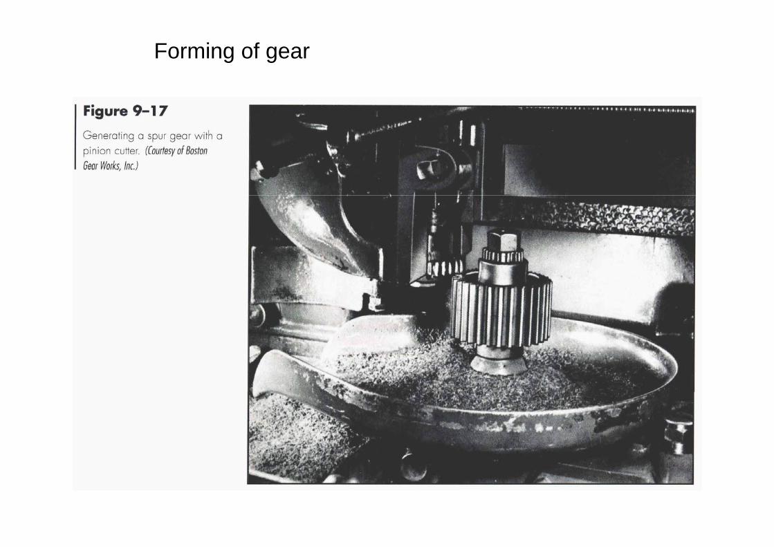
Forming of gear
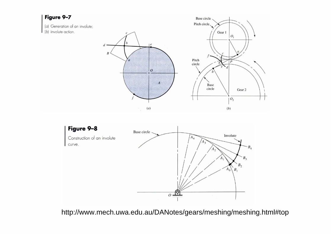
http://www.mech.uwa.edu.au/DANotes/gears/meshing/meshing.html#top
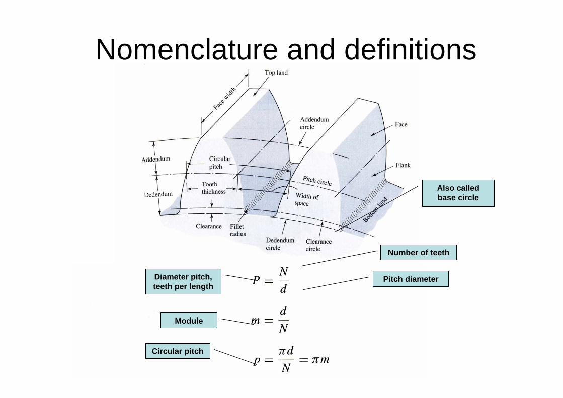
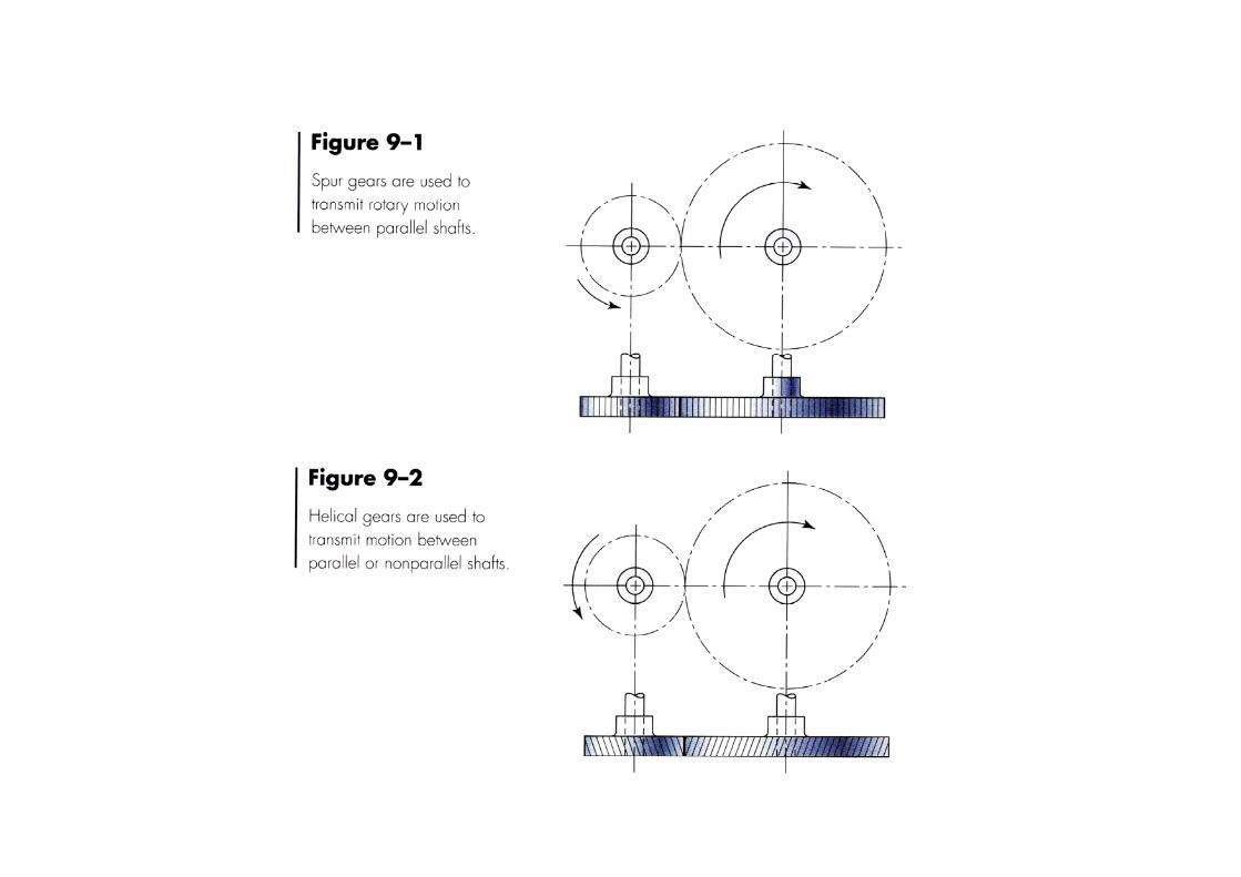
Nomenclature and definitions
Diameter pitch, teeth per length
Number of teeth
Pitch diameter
Module
Circular pitch
Also called base circle
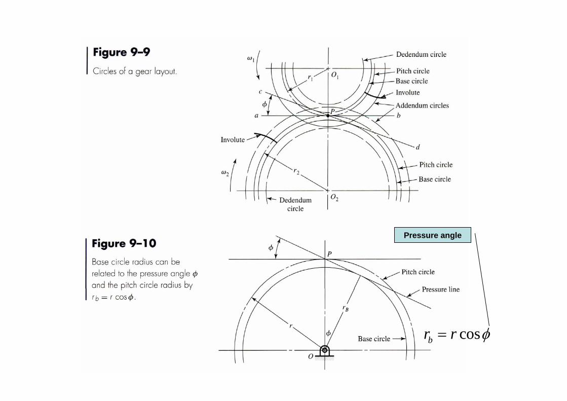
cosbr r φ=
Pressure angle
Example 1
A gear set consists of a 16 tooth pinion driving a 40 tooth gear. The module is 1. the gear are cut using a pressure angle of 20o.
(a) Compute the circular pitch, the center distance, and the radii of the base circles.
(b) In mounting these gears, the center distance was incorrectly made 2 mm larger. Compute the new values of the pressure angle and pitch-circle diameters.
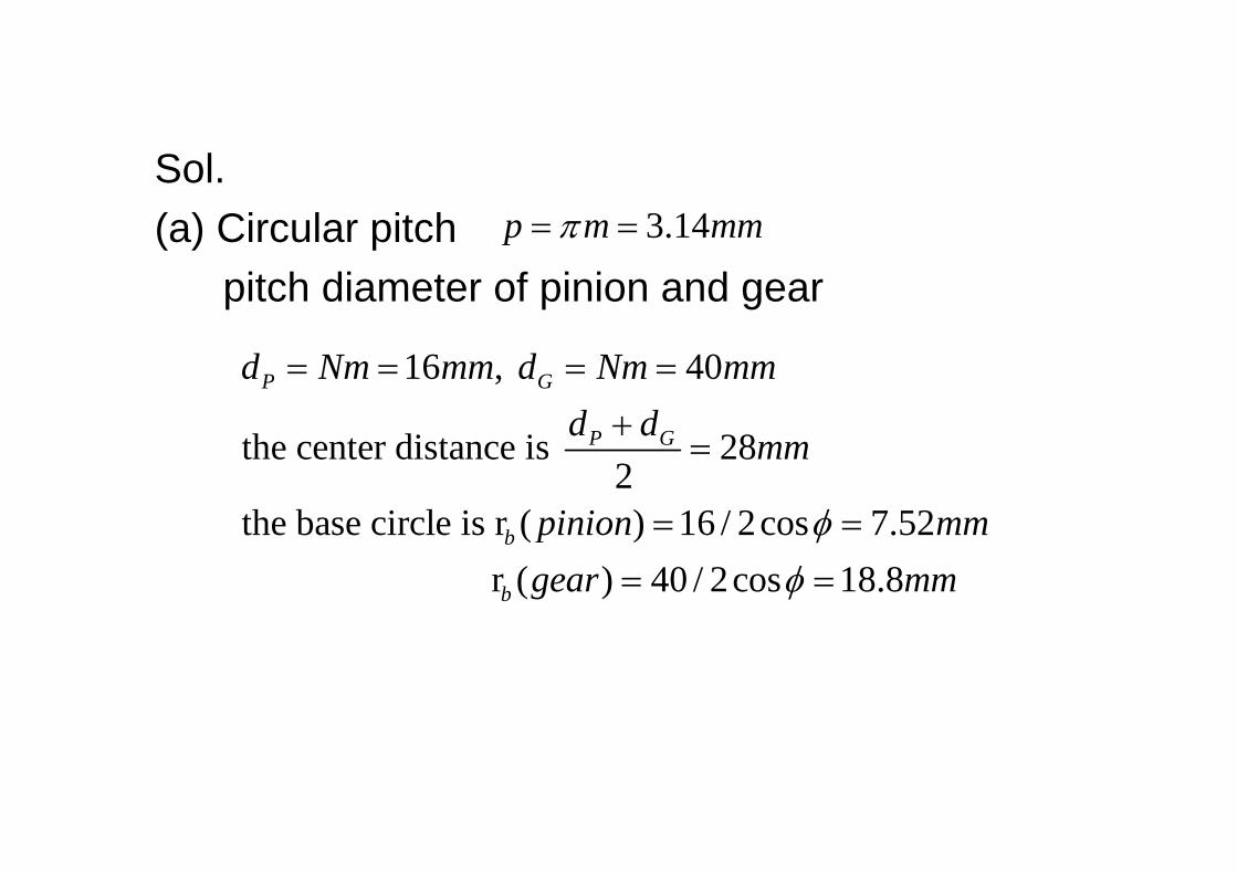
Sol.(a) Circular pitch
pitch diameter of pinion and gear
16 , 40
the center distance is 282
the base circle is r ( ) 16 / 2cos 7.52 r ( ) 40 / 2cos 18.8
P G
P G
b
b
d Nm mm d Nm mmd d mm
pinion mmgear mm
φφ
= = = =+
=
= == =
3.14p m mmπ= =
1
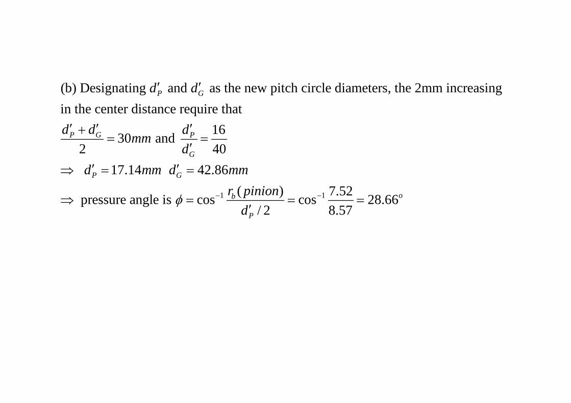
(b) Designating and as the new pitch circle diameters, the 2mm increasing in the center distance require that
1630 and 2 40 17.14 42.86
pressure angle is cos
P G
P G P
G
P G
d d
d d dmmd
d mm d mm
φ −
′ ′
′ ′ ′+= =
′
′ ′⇒ = =
⇒ = 1( ) 7.52cos 28.66/ 2 8.57
ob
P
r piniond
−= =′
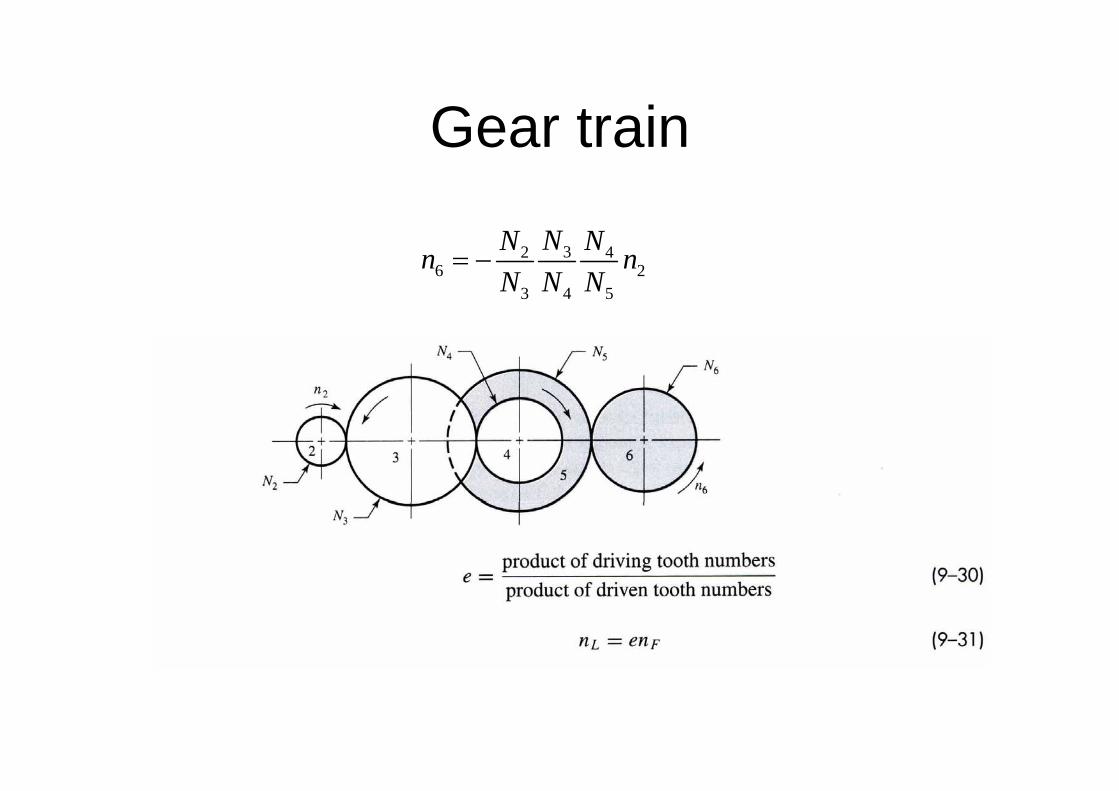
Gear train
32 46 2
3 4 5
NN Nn nN N N
= −
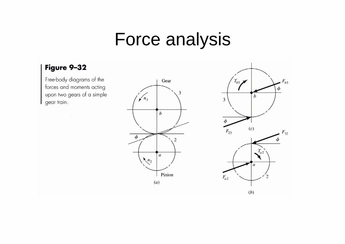
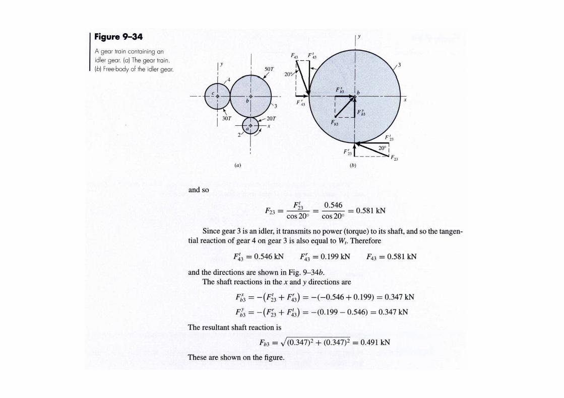
Force analysis
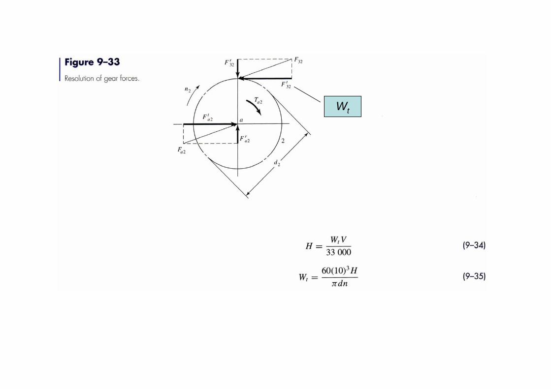
Wt
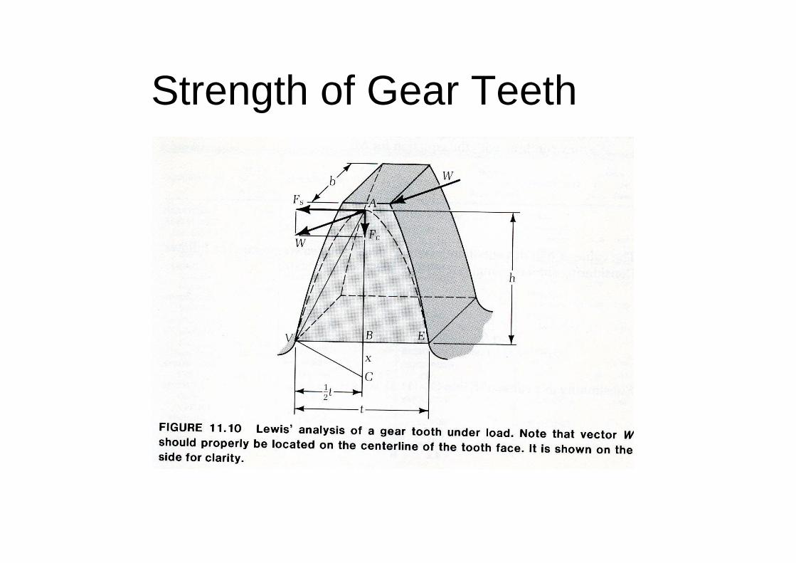
Strength of Gear Teeth
322
2
2
3232 32 32
2
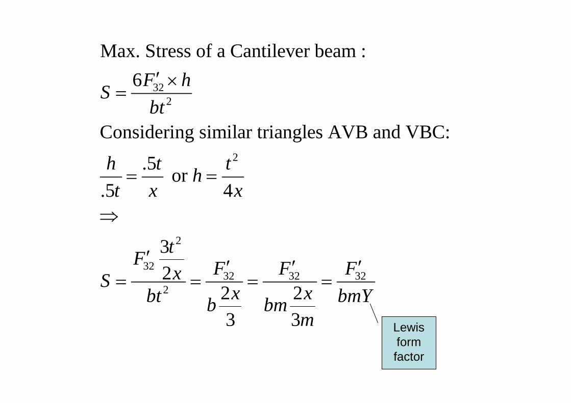
Max. Stress of a Cantilever beam :6
Considering similar triangles AVB and VBC:.5 or
.5 4
32
2 23 3
F hSbt
h t tht x x
tF F F FxS x xbt bmYb bmm
′ ×=
= =
⇒
′ ′ ′ ′= = = =
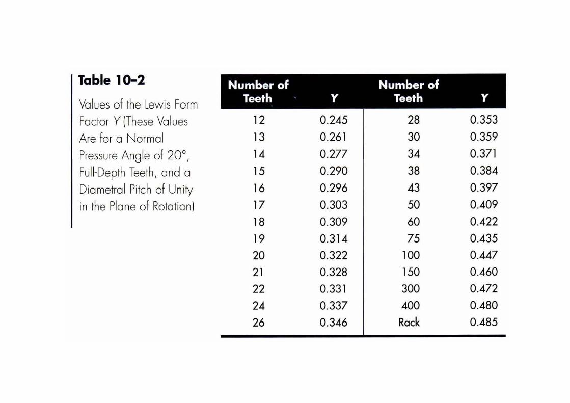
Lewis form factor
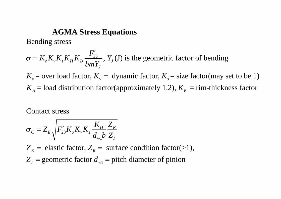
AGMA Stress Equations
23
Bending stress
, (J) is the geometric factor of bending
= over load factor, dynamic factor, = size factor(may set to be 1)= load distribution factor(approximately 1.2),
o v s H B JJ
o v s
H
FK K K K K YbmY
K K KK K
σ′
=
=
231
1
= rim-thickness factor
Contact stress
elastic factor, surface condition factor(>1), geometric factor pitch diameter of pinion
B
H RC E o v s
w I
E R
I w
K ZZ F K K Kd b Z
Z ZZ d
σ ′=
= == =
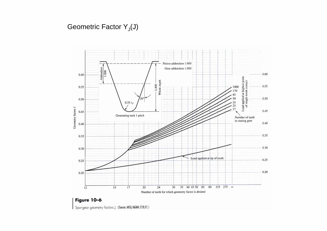
Geometric Factor YJ(J)
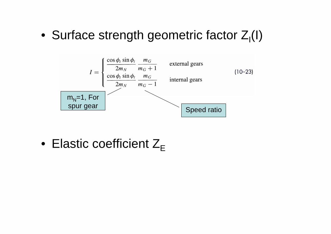
• Surface strength geometric factor ZI(I)
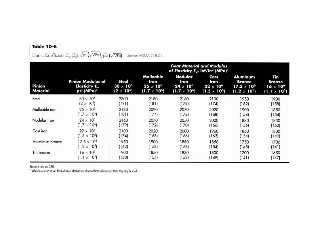
• Elastic coefficient ZE
mN=1, For spur gear Speed ratio
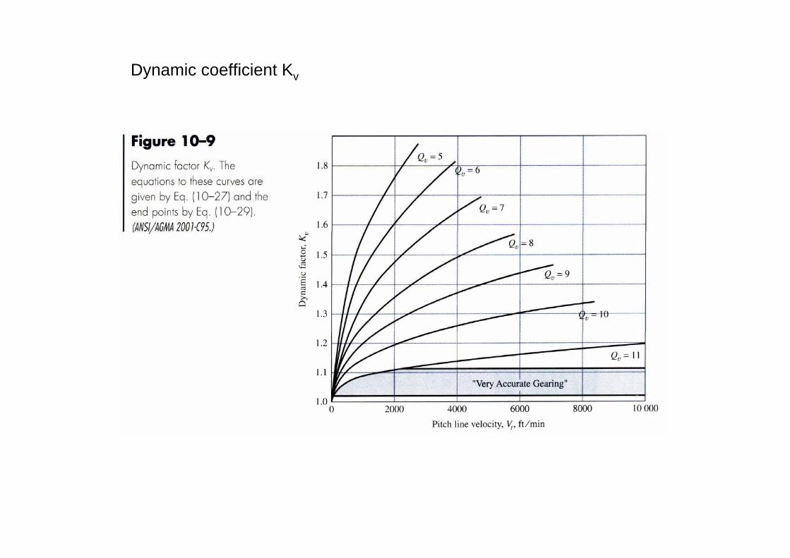
Dynamic coefficient Kv
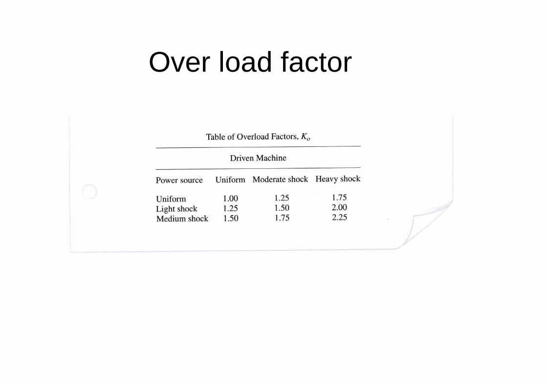
Over load factor
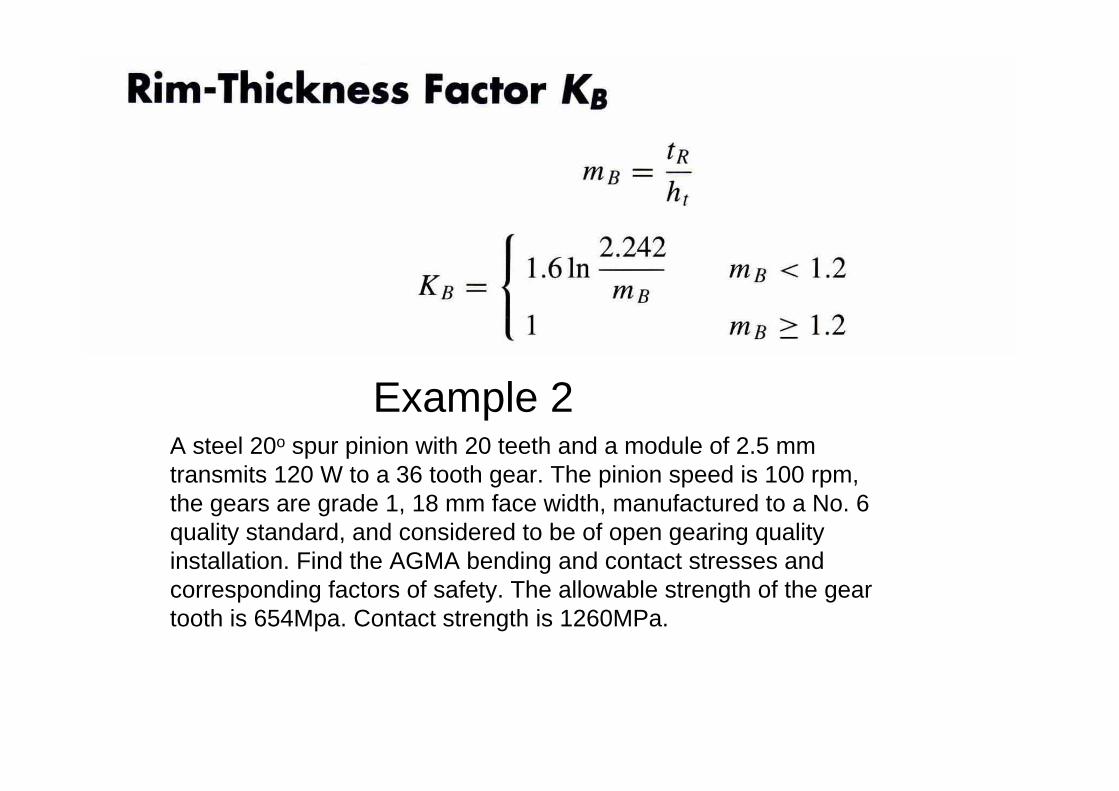
Example 2A steel 20o spur pinion with 20 teeth and a module of 2.5 mm transmits 120 W to a 36 tooth gear. The pinion speed is 100 rpm,the gears are grade 1, 18 mm face width, manufactured to a No. 6quality standard, and considered to be of open gearing quality installation. Find the AGMA bending and contact stresses and corresponding factors of safety. The allowable strength of the gear tooth is 654Mpa. Contact strength is 1260MPa.
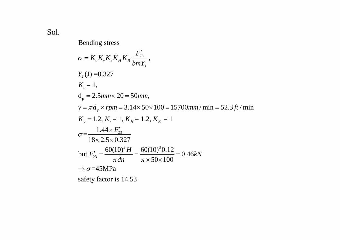
Sol.
23
p
23
3 3
23
Bending stress
,
(J) =0.327= 1,
d 2.5 20 50 ,
3.14 50 100 15700 / min 52.3 / min
1.2, = 1, = 1.2, = 11.44=
18 2.5 0.32760(10) 60(10) 0.1but
o v s H BJ
J
o
p
v s H B
FK K K K KbmY
YK
mm mm
v d rpm mm ft
K K K KF
HFdn
σ
π
σ
π
′=
= × =
= × = × × = =
=′×
× ×
′ = =2 0.46
50 100=45MPa
safety factor is 14.53
kNπ
σ
=× ×
⇒
231
1
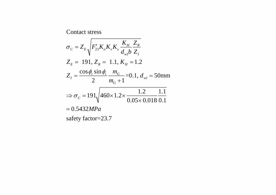
Contact stress
191, 1.1, 1.2cos sin =0.1, 50mm
2 1
1.2 1.1191 460 1.20.05 0.018 0.1
0.5432safety factor=23.7
H RC E o v s
w I
E R H
t t GI w
G
C
K ZZ F K K Kd b Z
Z Z KmZ d
m
MPa
σ
φ φ
σ
′=
= = =
= =+
⇒ = × ××
=
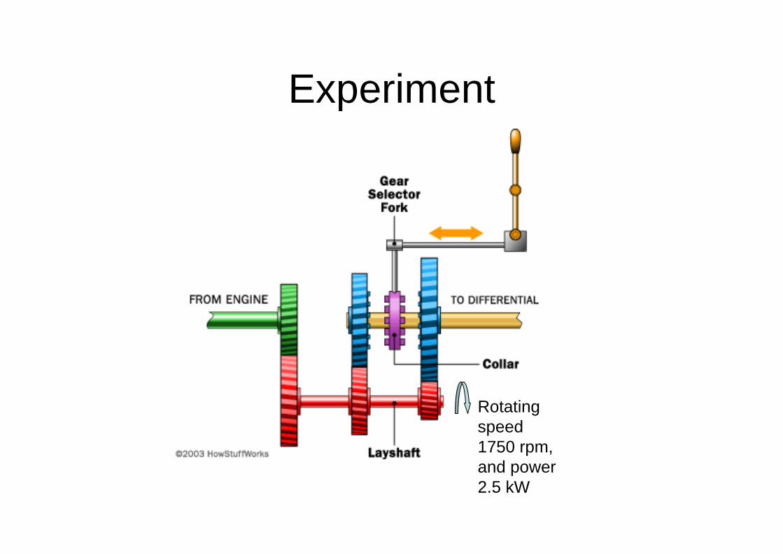
Experiment
Rotating speed 1750 rpm, and power 2.5 kW
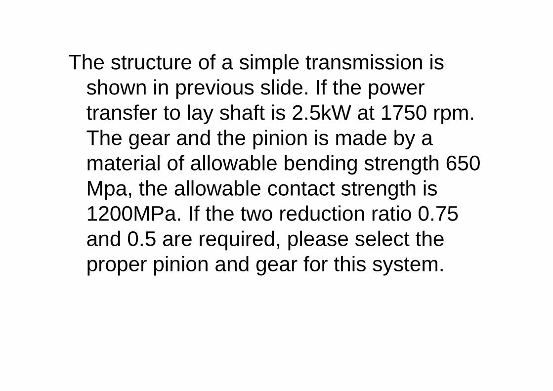
The structure of a simple transmission is shown in previous slide. If the power transfer to lay shaft is 2.5kW at 1750 rpm. The gear and the pinion is made by a material of allowable bending strength 650 Mpa, the allowable contact strength is 1200MPa. If the two reduction ratio 0.75 and 0.5 are required, please select the proper pinion and gear for this system.