Exam 2 Cheat Sheet
3
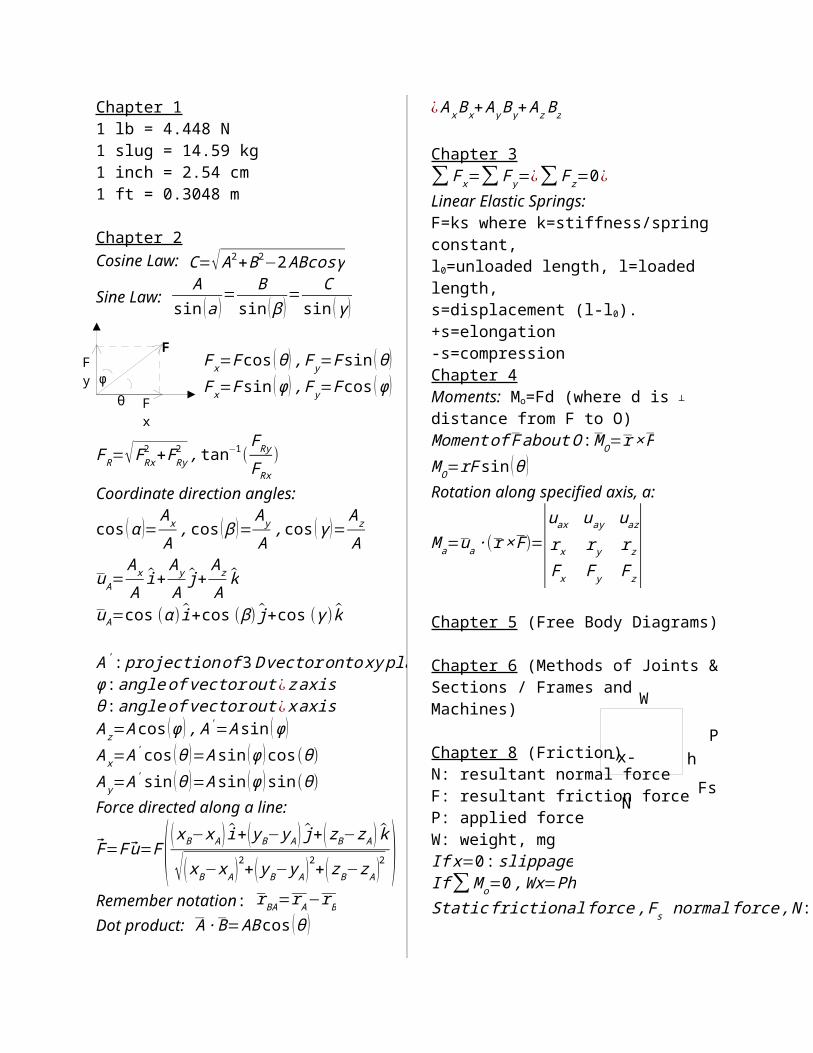
φ F F x F y N W Fs P -x- h Chapter 1 1 lb = 4.448 N 1 slug = 14.59 kg 1 inch = 2.54 cm 1 ft = 0.3048 m Chapter 2 Cosine Law: C= √ A 2 +B 2 −2 ABcosγ Sine Law: A sin ( a ) = B sin ( β ) = C sin ( γ) F R = √ F Rx 2 +F Ry 2 , tan −1 ( F Ry F Rx ) Coordinate direction angles: cos ( α )= A x A , cos ( β ) = A y A , cos ( γ) = A z A u A = A x A ^ i + A y A ^ j+ A z A ^ k u A =cos ( α ) ^ i +cos ( β) ^ j+cos ( γ ) ^ k A ' : projectionof 3 D vector onto xy pla φ : angle of vector out ¿ zaxis θ : angle of vector out ¿ xaxis A z =A cos ( φ ) ,A ' =A sin ( φ) A x =A ' cos ( θ ) =A sin ( φ ) cos ( θ) A y =A ' sin ( θ ) =A sin ( φ ) sin ( θ) Force directed along a line: F=F u=F ( ( x B −x A ) ^ i + ( y B −y A ) ^ j+ ( z B −z A ) ^ k √ ( x B −x A ) 2 + ( y B −y A ) 2 + ( z B −z A ) 2 ) Remember notation: r BA = r A − r B Dot product: A∙ B= AB cos ( θ ) ¿ A x B x + A y B y + A z B z Chapter 3 ∑ F x = ∑ F y =¿ ∑ F z =0 ¿ Linear Elastic Springs: F=ks where k=stiffness/spring constant, l 0 =unloaded length, l=loaded length, s=displacement (l-l 0 ). +s=elongation -s=compression Chapter 4 Moments: M o =Fd (where d is ┴ distance from F to O) Momentof F about O : M O = r× F M O =rF sin ( θ ) Rotation along specified axis, a: M a = u a ∙( r× F)= | u ax u ay u az r x r y r z F x F y F z | Chapter 5 (Free Body Diagrams) Chapter 6 (Methods of Joints & Sections / Frames and Machines) Chapter 8 (Friction) N: resultant normal force F: resultant friction force P: applied force W: weight, mg If x=0: slippage If ∑ M o =0 , Wx=Ph Static frictional force ,F s normalforce,N : θ F x =F cos ( θ) ,F y =F sin ( θ) F x =F sin ( φ) ,F y =F cos ( φ)
-
Upload
john-h-doe -
Category
Documents
-
view
16 -
download
4
Transcript of Exam 2 Cheat Sheet
φ
F
Fx
Fy
N
W
Fs
P-x- h
N
Fs
Rsφs
Chapter 11 lb = 4.448 N1 slug = 14.59 kg1 inch = 2.54 cm1 ft = 0.3048 m
Chapter 2Cosine Law: C=√ A2+B2−2 ABcosγ
Sine Law: A
sin (a )= B
sin ( β )= C
sin (γ )
FR=√FRx2 +FRy
2 , tan−1(F Ry
F Rx
)
Coordinate direction angles:
cos (α )=Ax
A, cos ( β )=
Ay
A,cos (γ )=
A z
A
uA=Ax
Ai+
A y
Aj+
A z
Ak
uA=cos (α )i+cos (β) j+cos (γ ) k
A' : projection of 3 D vector onto xy planeφ : angle of vector out ¿ zaxisθ :angle of vector out ¿x axisA z=A cos (φ ) , A '=A sin (φ )Ax=A' cos (θ )=A sin (φ ) cos(θ)A y=A ' sin (θ )=A sin (φ )sin(θ)Force directed along a line:
F=F u=F( ( xB−x A ) i+ ( yB− y A ) j+( z B−z A ) k
√( xB−x A )2+( yB− y A )2+( zB−z A )2 )Remember notation: r BA=r A−r B
Dot product: A ∙ B=AB cos (θ )¿ Ax Bx+ A y By+ A z B z
Chapter 3∑ F x=∑ F y=¿∑ F z=0¿ Linear Elastic Springs:F=ks where k=stiffness/spring constant,l0=unloaded length, l=loaded length,s=displacement (l-l0). +s=elongation
-s=compressionChapter 4Moments: Mo=Fd (where d is ┴ distance from F to O)Moment of F about O : MO=r × FM O=rF sin (θ )Rotation along specified axis, a:
M a=ua∙(r× F)=|uax uay uaz
r x r y rz
Fx F y F z|
Chapter 5 (Free Body Diagrams)
Chapter 6 (Methods of Joints & Sections / Frames and Machines)
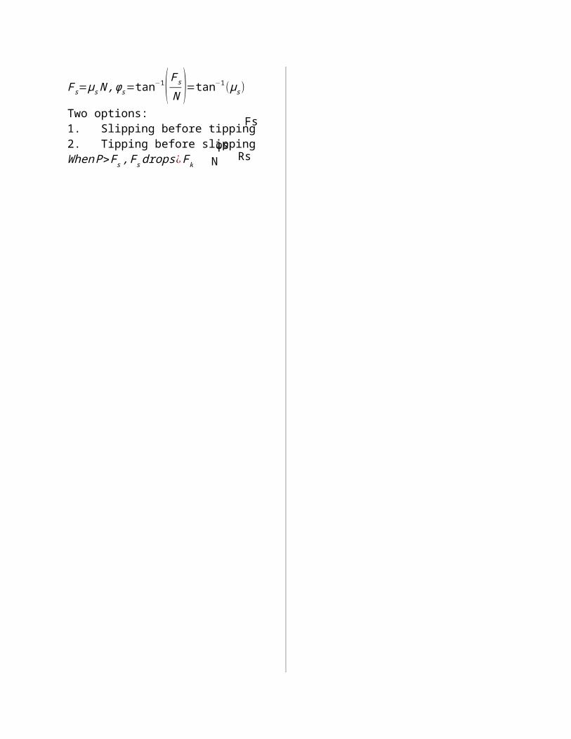
Chapter 8 (Friction)N: resultant normal forceF: resultant friction forceP: applied forceW: weight, mgIf x=0 : slippageIf ∑ M o=0 ,Wx=Ph Static frictional force , F s normal force , N :
F s=μs N ,φs=tan−1( F s
N )=tan−1(μs)
Two options:1. Slipping before tipping2. Tipping before slippingWhen P>F s , F sdrops ¿ Fk
θ
F x=F cos (θ ) , F y=F sin (θ )F x=F sin (φ ) ,F y=F cos (φ )