Energy in Steady Flow
31
1 Energy in Steady Flow Motion of a real fluid, Review A P Dec. 18, 2013 Dr. Celik
Transcript of Energy in Steady Flow
1
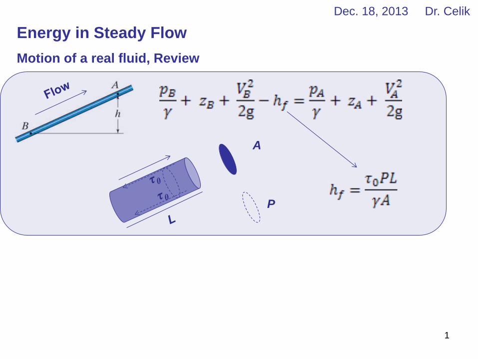
Energy in Steady Flow
Motion of a real fluid, Review
A
P
Dec. 18, 2013 Dr. Celik
2
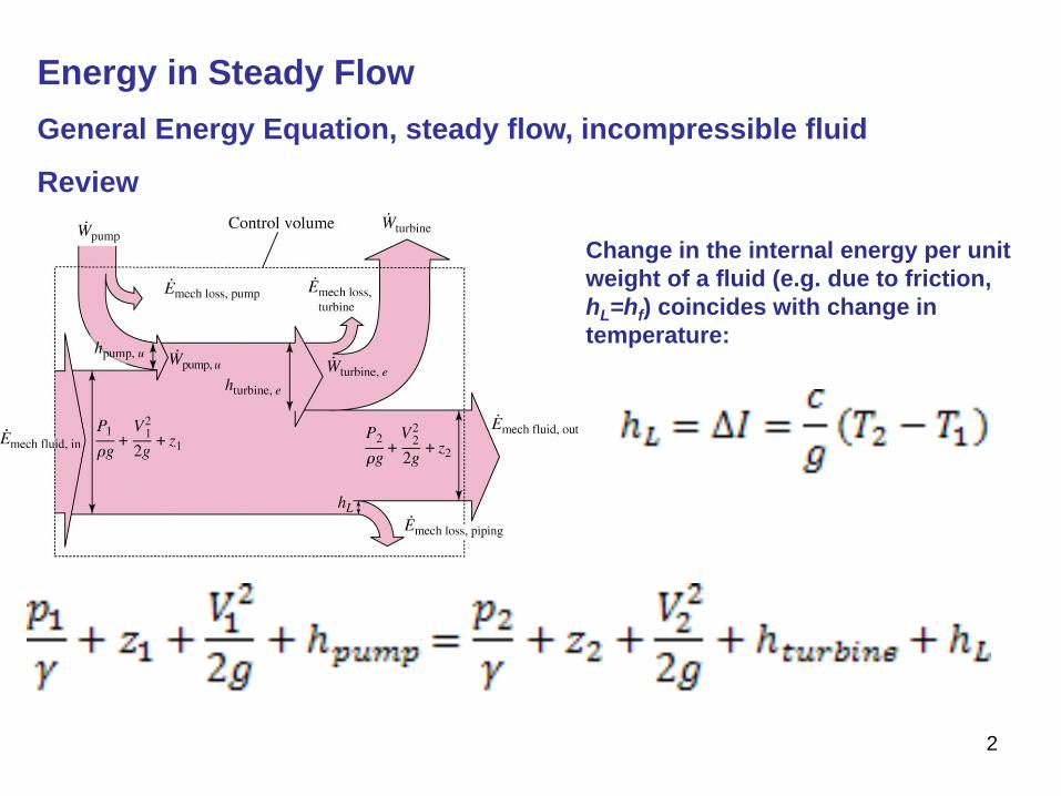
Energy in Steady Flow
General Energy Equation, steady flow, incompressible fluid
Review
Change in the internal energy per unit
weight of a fluid (e.g. due to friction,
hL=hf) coincides with change in
temperature:
3
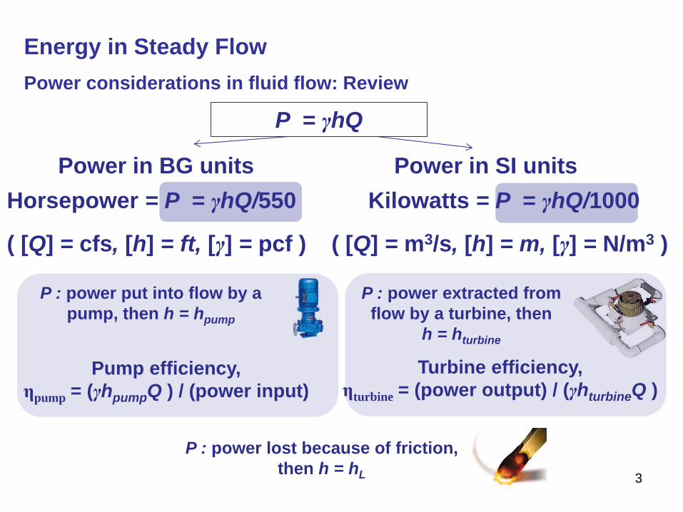
Energy in Steady Flow
Power considerations in fluid flow: Review
P = γhQ
Horsepower = P = γhQ/550
( [Q] = cfs, [h] = ft, [γ] = pcf )
Power in BG units
Kilowatts = P = γhQ/1000
( [Q] = m3/s, [h] = m, [γ] = N/m3 )
Power in SI units
Pump efficiency,
ηpump = (γhpumpQ ) / (power input)
P : power put into flow by a
pump, then h = hpump
P : power extracted from
flow by a turbine, then
h = hturbine
Turbine efficiency,
ηturbine = (power output) / (γhturbineQ )
P : power lost because of friction,
then h = hL
4
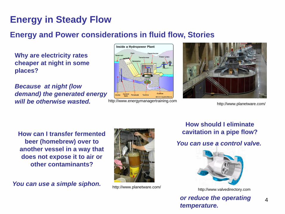
Energy in Steady Flow
Energy and Power considerations in fluid flow, Stories
Why are electricity rates
cheaper at night in some
places?
http://www.planetware.com/ http://www.energymanagertraining.com
How can I transfer fermented
beer (homebrew) over to
another vessel in a way that
does not expose it to air or
other contaminants?
Because at night (low
demand) the generated energy
will be otherwise wasted.
You can use a simple siphon. http://www.planetware.com/
How should I eliminate
cavitation in a pipe flow?
You can use a control valve.
http://www.valvedirectory.com
or reduce the operating
temperature.
5
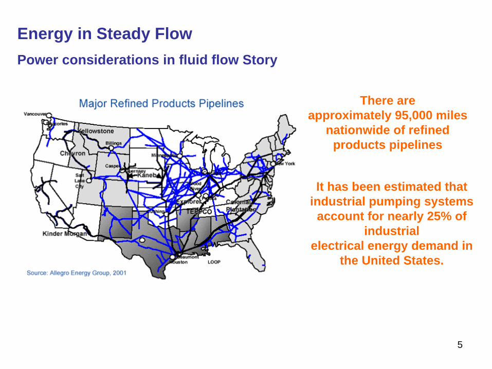
Energy in Steady Flow
Power considerations in fluid flow Story
There are
approximately 95,000 miles
nationwide of refined
products pipelines
It has been estimated that
industrial pumping systems
account for nearly 25% of
industrial
electrical energy demand in
the United States.
6
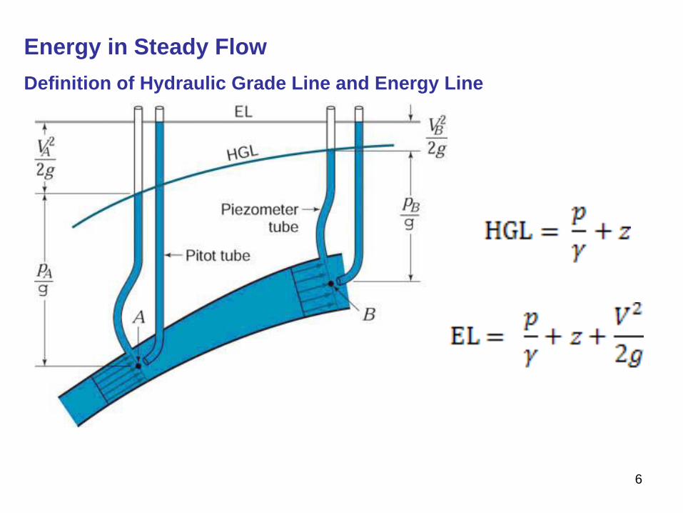
Energy in Steady Flow
Definition of Hydraulic Grade Line and Energy Line
7
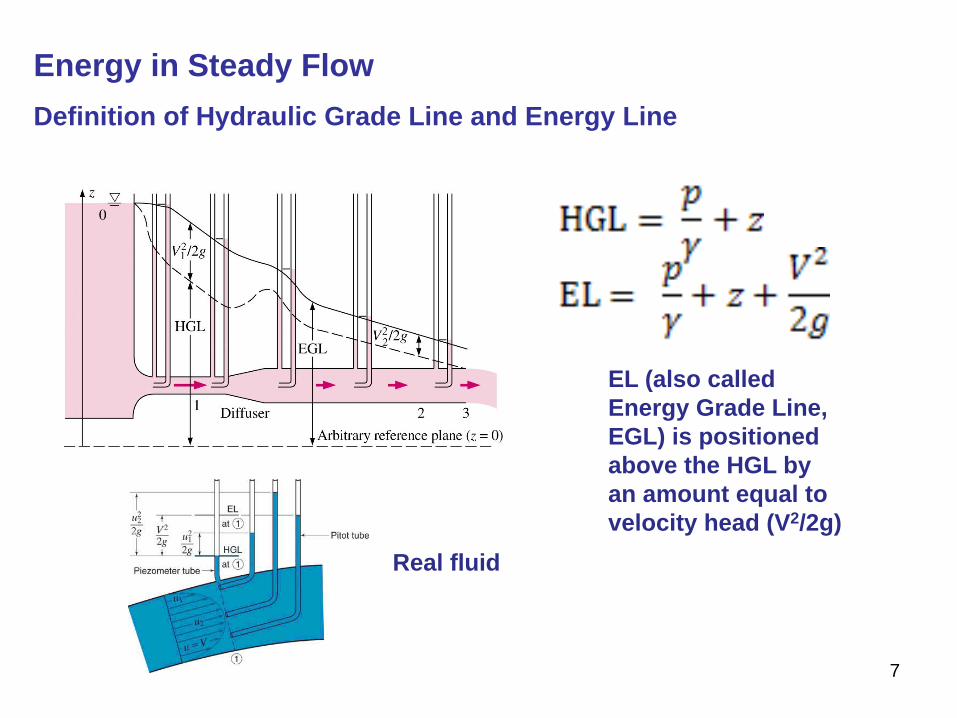
Energy in Steady Flow
Definition of Hydraulic Grade Line and Energy Line
Real fluid
EL (also called
Energy Grade Line,
EGL) is positioned
above the HGL by
an amount equal to
velocity head (V2/2g)
8
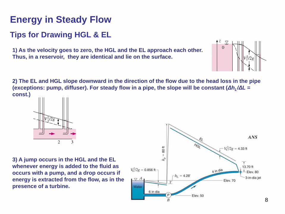
Energy in Steady Flow
Tips for Drawing HGL & EL
1) As the velocity goes to zero, the HGL and the EL approach each other.
Thus, in a reservoir, they are identical and lie on the surface.
2) The EL and HGL slope downward in the direction of the flow due to the head loss in the pipe
(exceptions: pump, diffuser). For steady flow in a pipe, the slope will be constant (ΔhL/ΔL =
const.)
3) A jump occurs in the HGL and the EL
whenever energy is added to the fluid as
occurs with a pump, and a drop occurs if
energy is extracted from the flow, as in the
presence of a turbine.
9
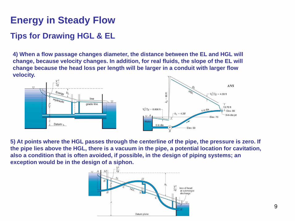
5) At points where the HGL passes through the centerline of the pipe, the pressure is zero. If
the pipe lies above the HGL, there is a vacuum in the pipe, a potential location for cavitation,
also a condition that is often avoided, if possible, in the design of piping systems; an
exception would be in the design of a siphon.
4) When a flow passage changes diameter, the distance between the EL and HGL will
change, because velocity changes. In addition, for real fluids, the slope of the EL will
change because the head loss per length will be larger in a conduit with larger flow
velocity.
Energy in Steady Flow
Tips for Drawing HGL & EL
10
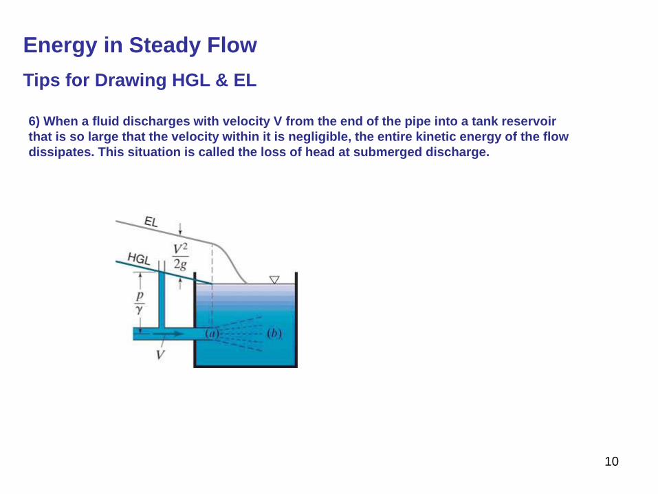
6) When a fluid discharges with velocity V from the end of the pipe into a tank reservoir
that is so large that the velocity within it is negligible, the entire kinetic energy of the flow
dissipates. This situation is called the loss of head at submerged discharge.
Energy in Steady Flow
Tips for Drawing HGL & EL
11
Energy in Steady Flow
Problem 2
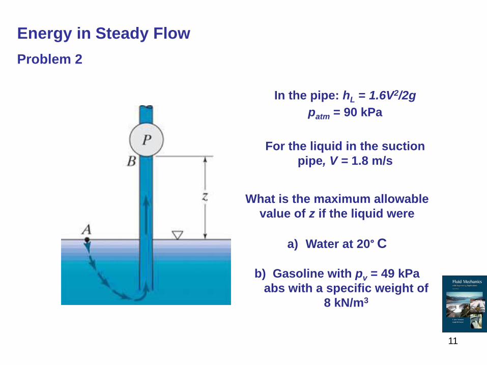
In the pipe: hL = 1.6V2/2g
patm = 90 kPa
For the liquid in the suction
pipe, V = 1.8 m/s
What is the maximum allowable
value of z if the liquid were
a) Water at 20° C
b) Gasoline with pv = 49 kPa
abs with a specific weight of
8 kN/m3
12
Energy in Steady Flow
Problem 2 , Solution
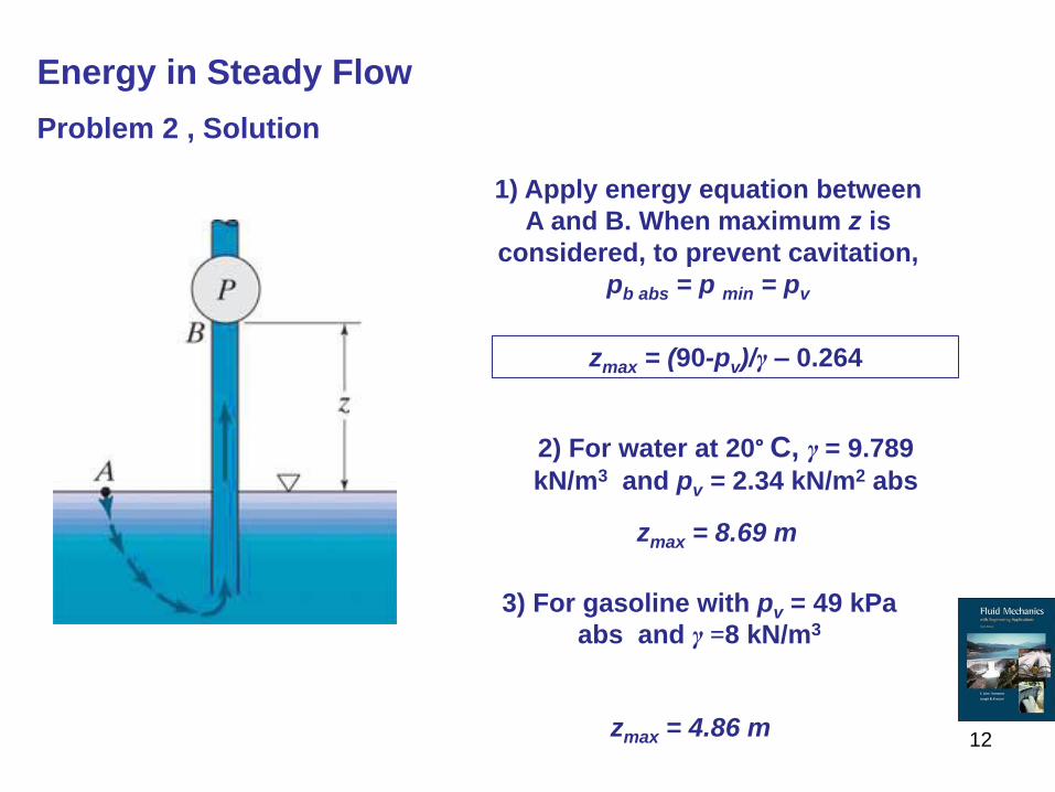
2) For water at 20° C, γ = 9.789
kN/m3 and pv = 2.34 kN/m2 abs
1) Apply energy equation between
A and B. When maximum z is
considered, to prevent cavitation,
pb abs = p min = pv
zmax = (90-pv)/γ – 0.264
zmax = 8.69 m
3) For gasoline with pv = 49 kPa
abs and γ =8 kN/m3
zmax = 4.86 m
13
Energy in Steady Flow
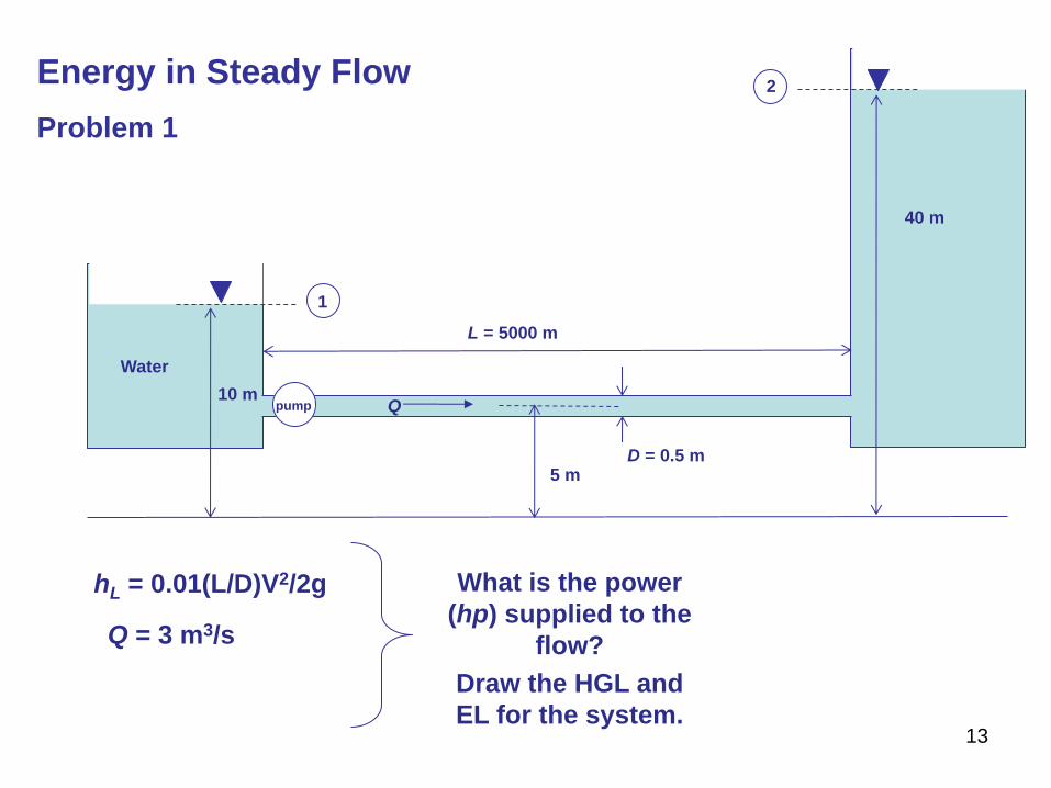
Problem 1
1
2
pump 10 m
L = 5000 m
Q
D = 0.5 m
40 m
hL = 0.01(L/D)V2/2g
Q = 3 m3/s
What is the power
(hp) supplied to the
flow?
Water
5 m
Draw the HGL and
EL for the system.
14
Energy in Steady Flow
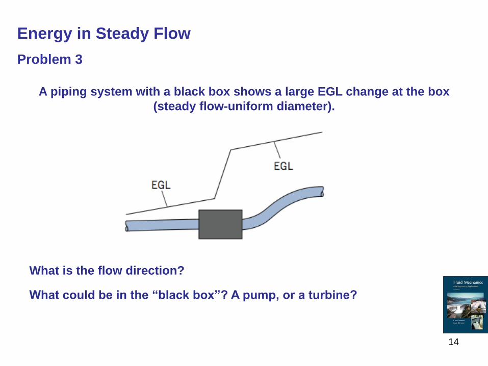
Problem 3
A piping system with a black box shows a large EGL change at the box
(steady flow-uniform diameter).
What is the flow direction?
What could be in the “black box”? A pump, or a turbine?
15
Energy in Steady Flow
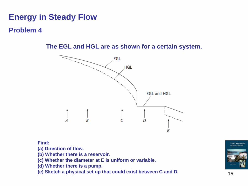
Problem 4
The EGL and HGL are as shown for a certain system.
Find:
(a) Direction of flow.
(b) Whether there is a reservoir.
(c) Whether the diameter at E is uniform or variable.
(d) Whether there is a pump.
(e) Sketch a physical set up that could exist between C and D.
16
Energy in Steady Flow
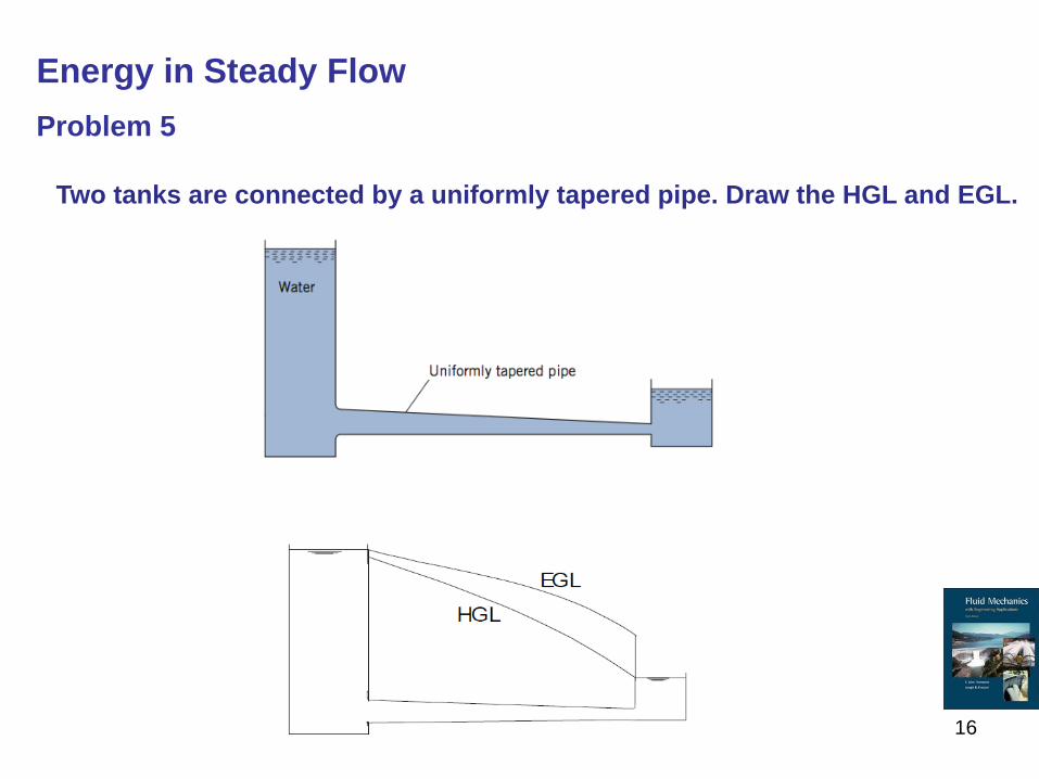
Problem 5
Two tanks are connected by a uniformly tapered pipe. Draw the HGL and EGL.
17
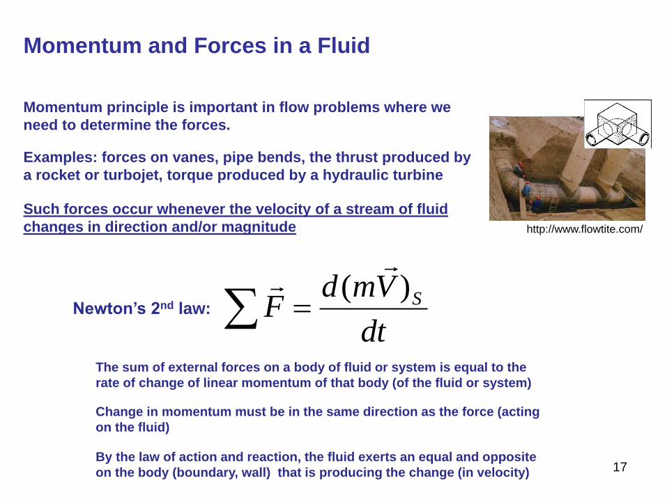
Momentum and Forces in a Fluid
dt
VmdF S)(
Newton’s 2nd law:
The sum of external forces on a body of fluid or system is equal to the
rate of change of linear momentum of that body (of the fluid or system)
Change in momentum must be in the same direction as the force (acting
on the fluid)
Momentum principle is important in flow problems where we
need to determine the forces.
Examples: forces on vanes, pipe bends, the thrust produced by
a rocket or turbojet, torque produced by a hydraulic turbine
http://www.flowtite.com/
By the law of action and reaction, the fluid exerts an equal and opposite
on the body (boundary, wall) that is producing the change (in velocity)
Such forces occur whenever the velocity of a stream of fluid
changes in direction and/or magnitude
18
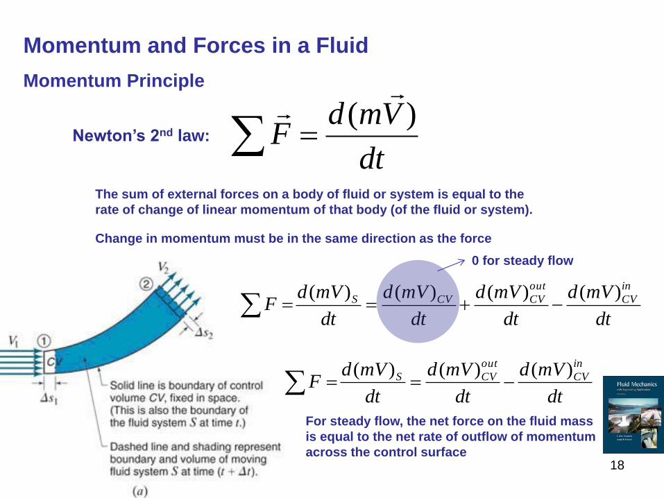
Momentum and Forces in a Fluid
Momentum Principle
dt
VmdF
)(
Newton’s 2nd law:
The sum of external forces on a body of fluid or system is equal to the
rate of change of linear momentum of that body (of the fluid or system).
Change in momentum must be in the same direction as the force
dt
mVd
dt
mVd
dt
mVd
dt
mVdF
in
CV
out
CVCVS )()()()(
dt
mVd
dt
mVd
dt
mVdF
in
CV
out
CVS )()()(
0 for steady flow
For steady flow, the net force on the fluid mass
is equal to the net rate of outflow of momentum
across the control surface
19
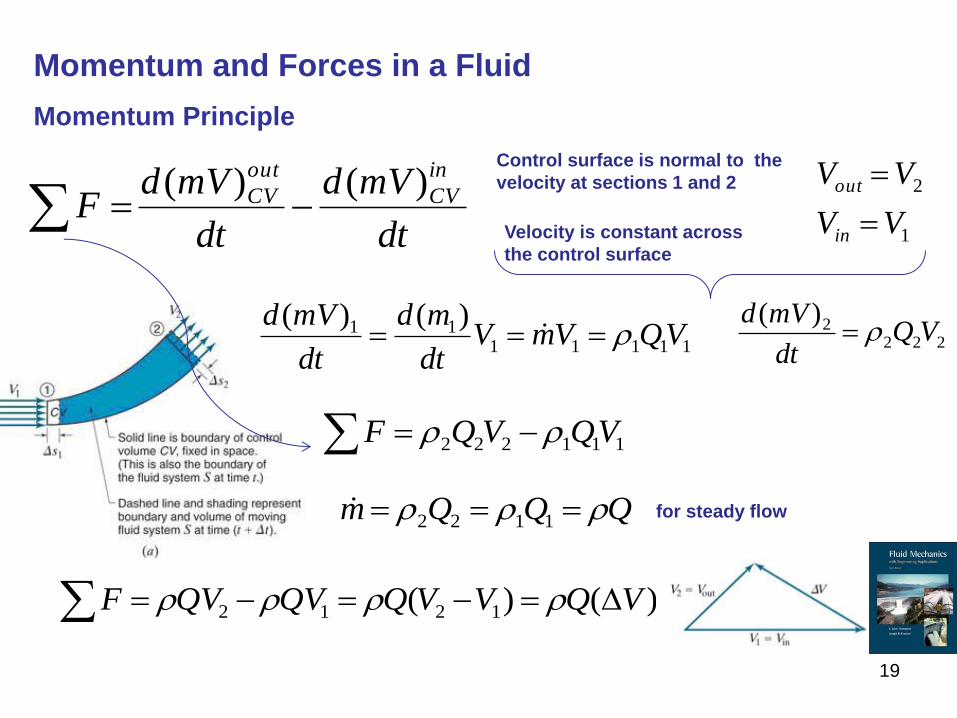
Momentum and Forces in a Fluid
Momentum Principle
dt
mVd
dt
mVdF
in
CV
out
CV )()(
Control surface is normal to the
velocity at sections 1 and 2
Velocity is constant across
the control surface
1111111 )()(
VQVmVdt
md
dt
mVd 222
2)(VQ
dt
mVd
111222 VQVQF
QQQm 1122 for steady flow
)()( 1212 VQVVQQVQVF
1
2
VV
VV
in
out
20
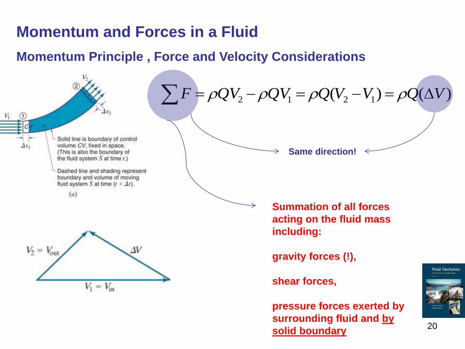
Momentum and Forces in a Fluid
Momentum Principle , Force and Velocity Considerations
)()( 1212 VQVVQQVQVF
Same direction!
Summation of all forces
acting on the fluid mass
including:
gravity forces (!),
shear forces,
pressure forces exerted by
surrounding fluid and by
solid boundary
21
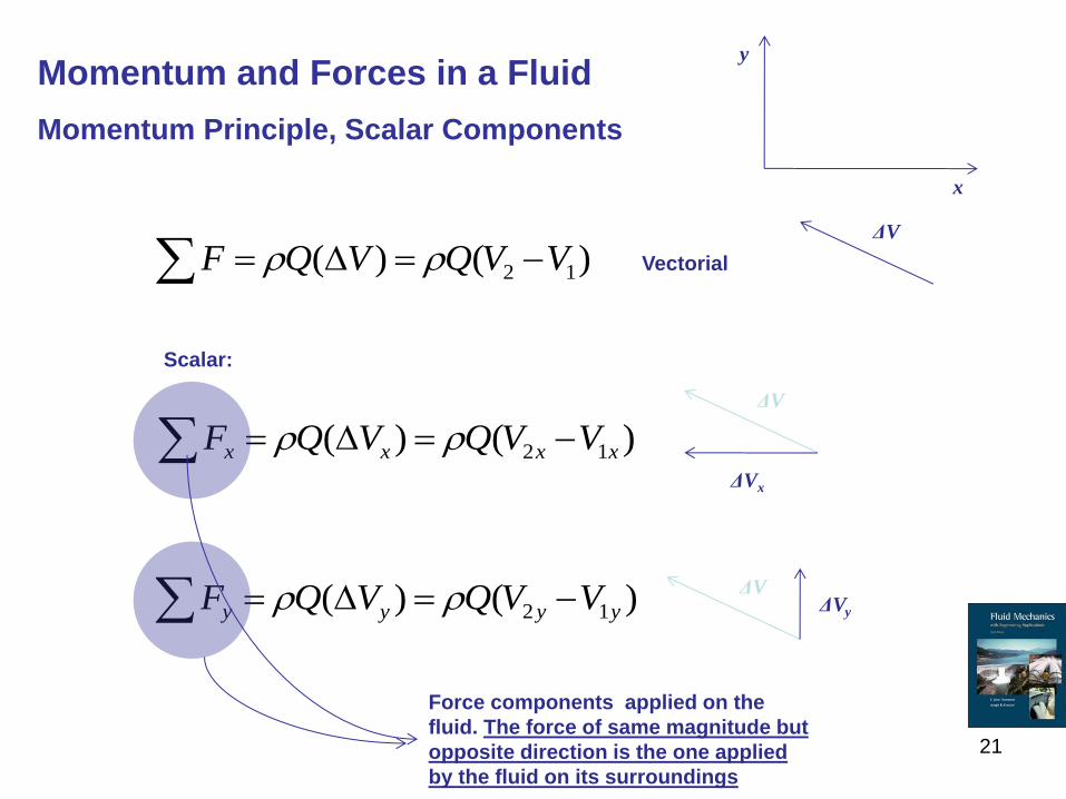
Momentum and Forces in a Fluid
Momentum Principle, Scalar Components
)()( 12 VVQVQF Vectorial
)()( 12 xxxx VVQVQF
ΔV
ΔV ΔVy
ΔV
ΔVx
)()( 12 yyyy VVQVQF
Scalar:
Force components applied on the
fluid. The force of same magnitude but
opposite direction is the one applied
by the fluid on its surroundings
x
y
22
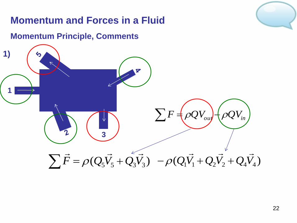
Momentum and Forces in a Fluid
Momentum Principle, Comments
inout QVQVF
1)
)( 3355 VQVQF
1
3
)( 442211 VQVQVQ
23
Momentum and Forces in a Fluid
Momentum Principle, Comments
2) Draw a suitable system of axes. It is important to establish positive x & y
directions for vectorial relationships.
3) Draw a suitable control volume(CV). The CV should include all the changes
that the velocity experiences (i.e. magnitude and direction)
4) For the summation of forces, all the external forces applied on the CV should
be considered. If we have Fx, then the x component of all the forces should be
included. Gravity is the force applied in the vertical direction
5) The result we find from the momentum principle is a force applied upon the CV.
Most often we are asked to determine the forces applied by the fluid. This is equal
in magnitude but opposite in direction compared to the former force.
6) We don’t need to know the energy losses or we don’t care how complicated the
flow field is when dealing with the momentum. We only need to know the
conditions at the end sections of our CV (and gravity forces).
7) The direction of the forces in x and y axes applied by the fluid are not known
before hand.
24
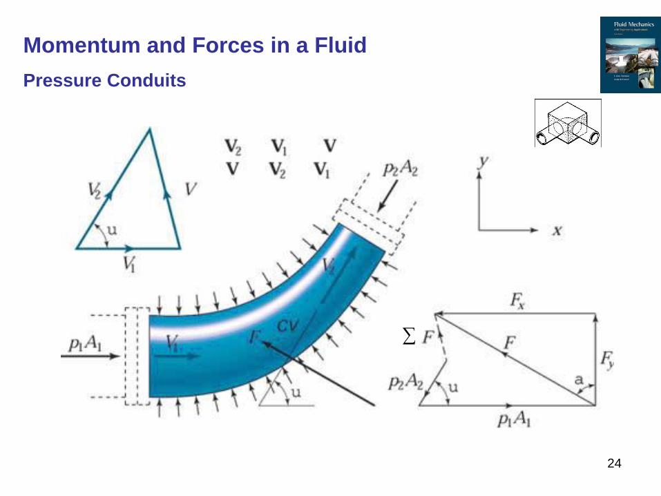
Momentum and Forces in a Fluid
Pressure Conduits
25
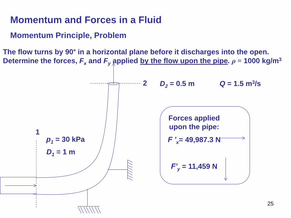
Momentum and Forces in a Fluid
Momentum Principle, Problem
The flow turns by 90° in a horizontal plane before it discharges into the open.
Determine the forces, Fx and Fy applied by the flow upon the pipe. ρ = 1000 kg/m3
1
2 D2 = 0.5 m Q = 1.5 m3/s
p1 = 30 kPa
D1 = 1 m
F ’x= 49,987.3 N
F’y = 11,459 N
Forces applied
upon the pipe:
26
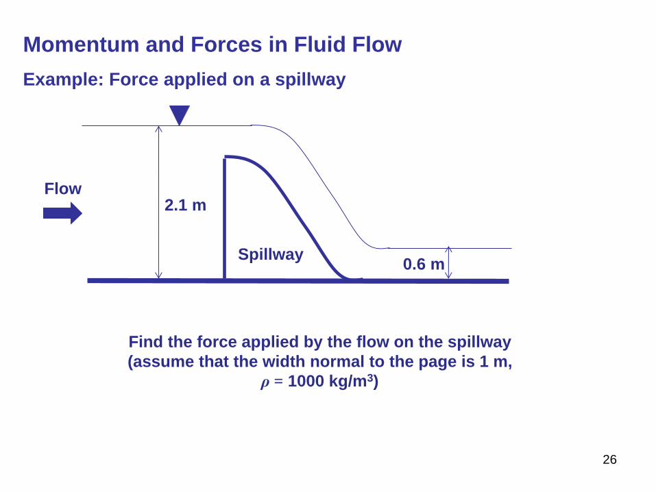
Momentum and Forces in Fluid Flow
Example: Force applied on a spillway
2.1 m
0.6 m
Flow
Spillway
Find the force applied by the flow on the spillway
(assume that the width normal to the page is 1 m,
ρ = 1000 kg/m3)
27
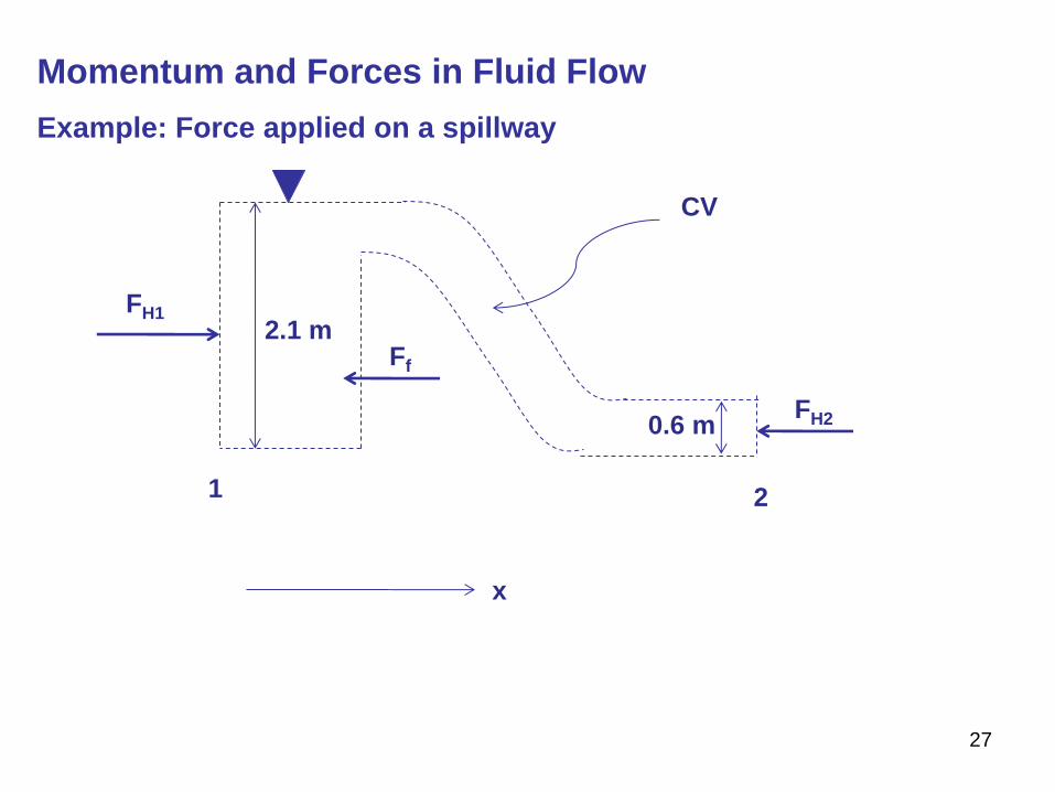
Momentum and Forces in Fluid Flow
Example: Force applied on a spillway
1 2
2.1 m
0.6 m
CV
FH1
FH2
Ff
x
28
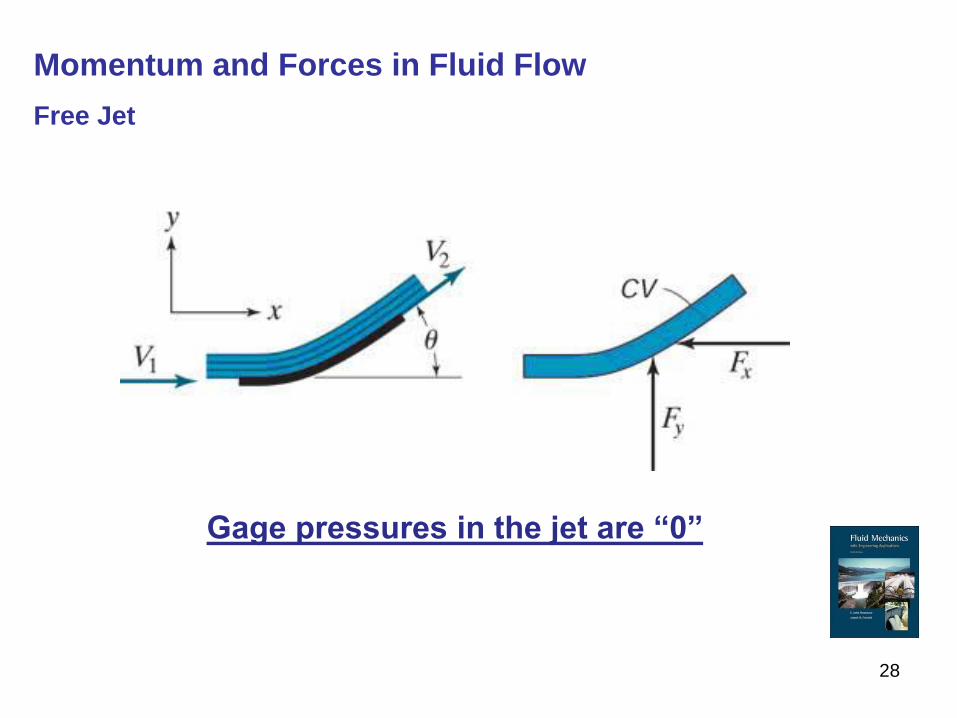
Momentum and Forces in Fluid Flow
Free Jet
Gage pressures in the jet are “0”
29
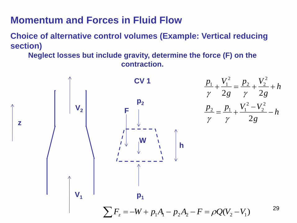
Momentum and Forces in Fluid Flow
Choice of alternative control volumes (Example: Vertical reducing
section)
V1
V2
CV 1
p2
p1
W
Neglect losses but include gravity, determine the force (F) on the
contraction.
z
F
)( 122211 VVQFApApWFz
hg
VVpp
hg
Vp
g
Vp
2
22
2
2
2
112
2
22
2
11
h
30
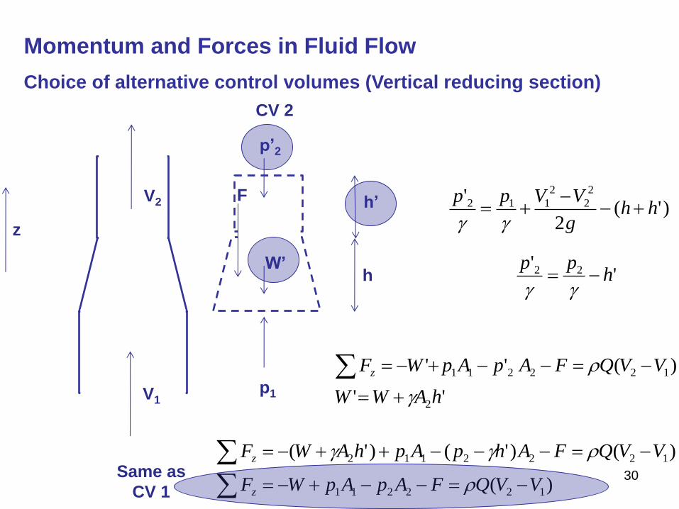
Momentum and Forces in Fluid Flow
Choice of alternative control volumes (Vertical reducing section)
V1
V2
CV 2
p’2
p1
W’
z
h
h’ F
)'(2
' 2
2
2
112 hhg
VVpp
'' 22 h
pp
''
)(''
2
122211
hAWW
VVQFApApWFz
)(
)()'()'(
122211
1222112
VVQFApApWF
VVQFAhpAphAWF
z
z
Same as
CV 1
31
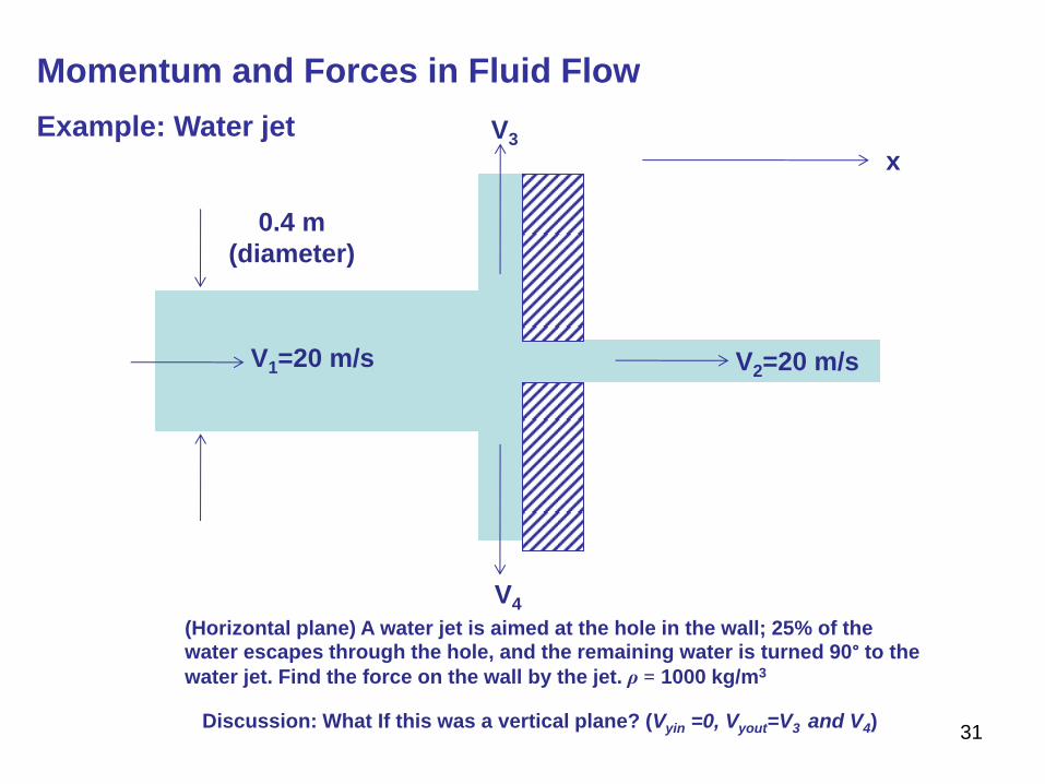
Momentum and Forces in Fluid Flow
Example: Water jet
(Horizontal plane) A water jet is aimed at the hole in the wall; 25% of the water escapes through the hole, and the remaining water is turned 90° to the
water jet. Find the force on the wall by the jet. ρ = 1000 kg/m3
0.4 m
(diameter)
V1=20 m/s V2=20 m/s
V3
V4
x
Discussion: What If this was a vertical plane? (Vyin =0, Vyout=V3 and V4)