
Electrostatic Fluid Engine Generator
21
Electrostatic Capacitive Energy Generation • Just as electricity is generated by using an inductor (wire coil) and changing magnetic fields, a changing electrostatic field can also produce electricity! The equation modeling magnetic voltage generation is: Vemf = B*A*cos(theta) where B = magnetic flux density, A = area of wire coil, ϴ = angle between wire coil & magnetic field direction vector An equation can be written for electrostatic voltage generation: V = Q/C where Q = charge, and C = capacitance
-
Upload
scott-olson -
Category
Documents
-
view
135 -
download
1
Transcript of Electrostatic Fluid Engine Generator
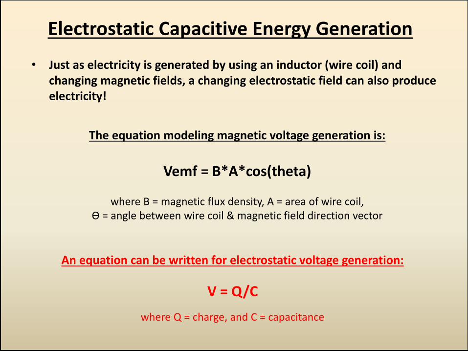
Electrostatic Capacitive Energy Generation
• Just as electricity is generated by using an inductor (wire coil) and changing magnetic fields, a changing electrostatic field can also produce electricity!
The equation modeling magnetic voltage generation is:
Vemf = B*A*cos(theta)
where B = magnetic flux density, A = area of wire coil,
ϴ = angle between wire coil & magnetic field direction vector
An equation can be written for electrostatic voltage generation:
V = Q/C
where Q = charge, and C = capacitance
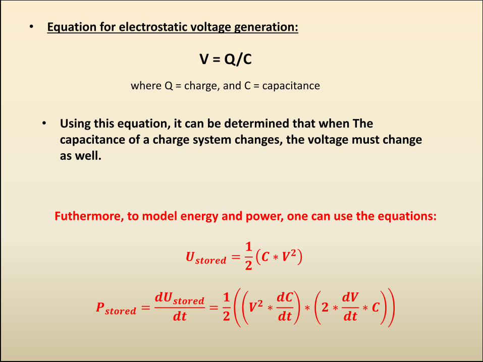
• Equation for electrostatic voltage generation:
V = Q/C
where Q = charge, and C = capacitance
• Using this equation, it can be determined that when The capacitance of a charge system changes, the voltage must change as well.
Futhermore, to model energy and power, one can use the equations:
𝑼𝒔𝒕𝒐𝒓𝒆𝒅 =𝟏
𝟐𝑪 ∗ 𝑽𝟐
𝑷𝒔𝒕𝒐𝒓𝒆𝒅 =𝒅𝑼𝒔𝒕𝒐𝒓𝒆𝒅
𝒅𝒕=
𝟏
𝟐𝑽𝟐 ∗
𝒅𝑪
𝒅𝒕∗ 𝟐 ∗
𝒅𝑽
𝒅𝒕∗ 𝑪
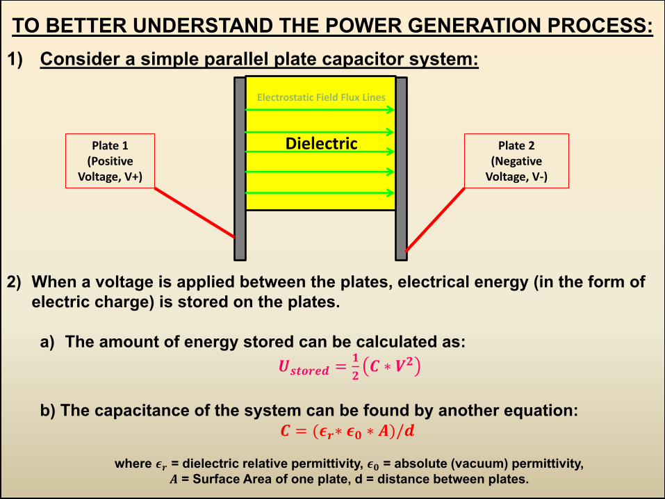
TO BETTER UNDERSTAND THE POWER GENERATION PROCESS:
1) Consider a simple parallel plate capacitor system:
2) When a voltage is applied between the plates, electrical energy (in the form of
electric charge) is stored on the plates.
a) The amount of energy stored can be calculated as:
𝑼𝒔𝒕𝒐𝒓𝒆𝒅 =𝟏
𝟐𝑪 ∗ 𝑽𝟐
b) The capacitance of the system can be found by another equation:
𝑪 = (𝝐𝒓∗ 𝝐𝟎 ∗ 𝑨)/𝒅
where 𝝐𝒓 = dielectric relative permittivity, 𝝐𝟎 = absolute (vacuum) permittivity,
𝑨 = Surface Area of one plate, d = distance between plates.
Plate 1 (Positive
Voltage, V+)
Plate 2 (Negative
Voltage, V-)
Dielectric
Electrostatic Field Flux Lines
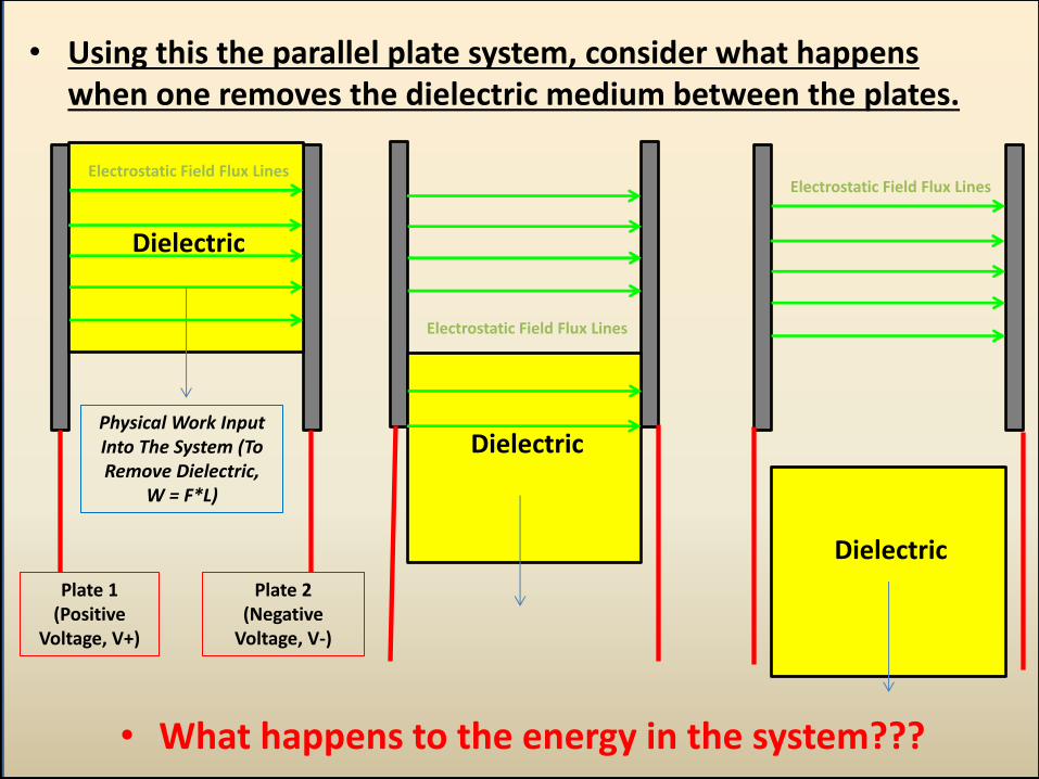
Plate 1 (Positive
Voltage, V+)
Plate 2 (Negative
Voltage, V-)
Dielectric
• Using this the parallel plate system, consider what happens when one removes the dielectric medium between the plates.
Dielectric
• What happens to the energy in the system???
Physical Work Input Into The System (To Remove Dielectric,
W = F*L)
Electrostatic Field Flux Lines
Dielectric
Electrostatic Field Flux Lines
Electrostatic Field Flux Lines
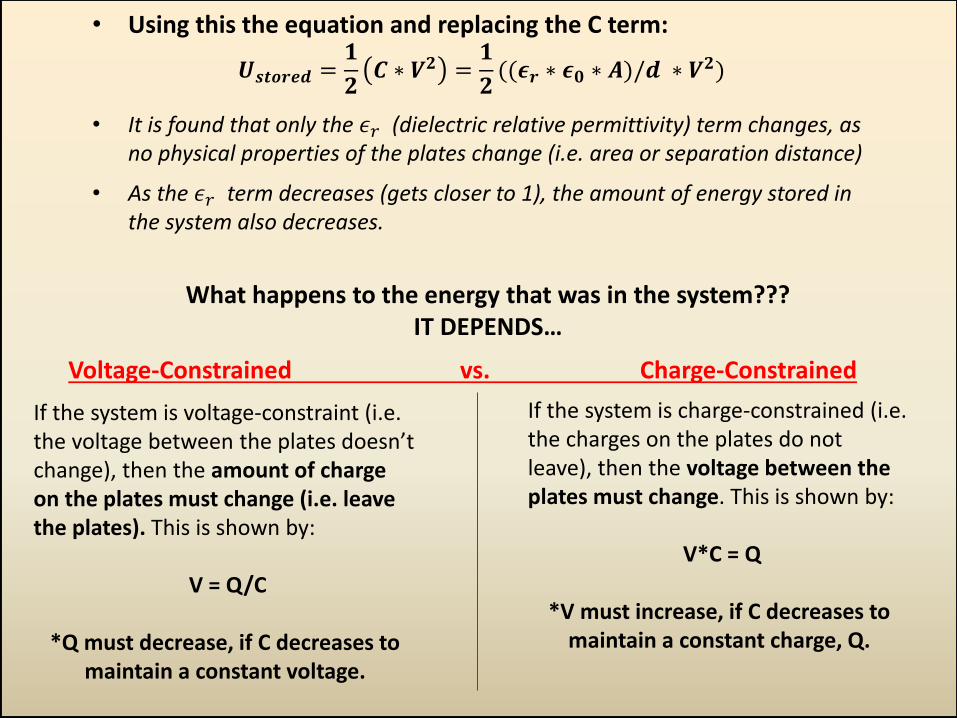
• Using this the equation and replacing the C term:
𝑼𝒔𝒕𝒐𝒓𝒆𝒅 =𝟏
𝟐𝑪 ∗ 𝑽𝟐 =
𝟏
𝟐((𝝐𝒓 ∗ 𝝐𝟎 ∗ 𝑨)/𝒅 ∗ 𝑽𝟐)
• It is found that only the 𝜖𝑟 (dielectric relative permittivity) term changes, as no physical properties of the plates change (i.e. area or separation distance)
• As the 𝜖𝑟 term decreases (gets closer to 1), the amount of energy stored in the system also decreases.
What happens to the energy that was in the system??? IT DEPENDS…
If the system is voltage-constraint (i.e. the voltage between the plates doesn’t change), then the amount of charge on the plates must change (i.e. leave the plates). This is shown by:
V = Q/C
*Q must decrease, if C decreases to
maintain a constant voltage.
If the system is charge-constrained (i.e. the charges on the plates do not leave), then the voltage between the plates must change. This is shown by:
V*C = Q
*V must increase, if C decreases to
maintain a constant charge, Q.
Voltage-Constrained vs. Charge-Constrained
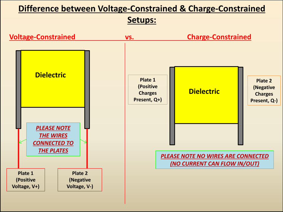
Difference between Voltage-Constrained & Charge-Constrained Setups:
Voltage-Constrained vs. Charge-Constrained
Plate 1 (Positive
Voltage, V+)
Plate 2 (Negative
Voltage, V-)
Dielectric Plate 1
(Positive Charges
Present, Q+)
Plate 2 (Negative Charges
Present, Q-)
Dielectric
PLEASE NOTE THE WIRES
CONNECTED TO THE PLATES
PLEASE NOTE NO WIRES ARE CONNECTED (NO CURRENT CAN FLOW IN/OUT)
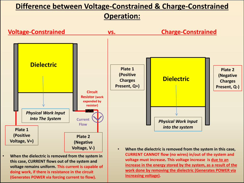
Difference between Voltage-Constrained & Charge-Constrained Operation:
Voltage-Constrained vs. Charge-Constrained
Plate 1 (Positive
Voltage, V+) Plate 2
(Negative Voltage, V-)
Dielectric Plate 1
(Positive Charges
Present, Q+)
Plate 2 (Negative Charges
Present, Q-)
Dielectric
• When the dielectric is removed from the system in this case, CURRENT flows out of the system and voltage remains uniform. This current is capable of doing work, if there is resistance in the circuit (Generates POWER via forcing current to flow).
Physical Work Input Into The System
• When the dielectric is removed from the system in this case, CURRENT CANNOT flow (no wires) in/out of the system and voltage must increase. This voltage increase is due to an increase in the energy stored by the system, as a result of the work done by removing the dielectric (Generates POWER via increasing voltage).
Physical Work Input into the system
Current Flow
Circuit Resistor (work
expended by resistor)
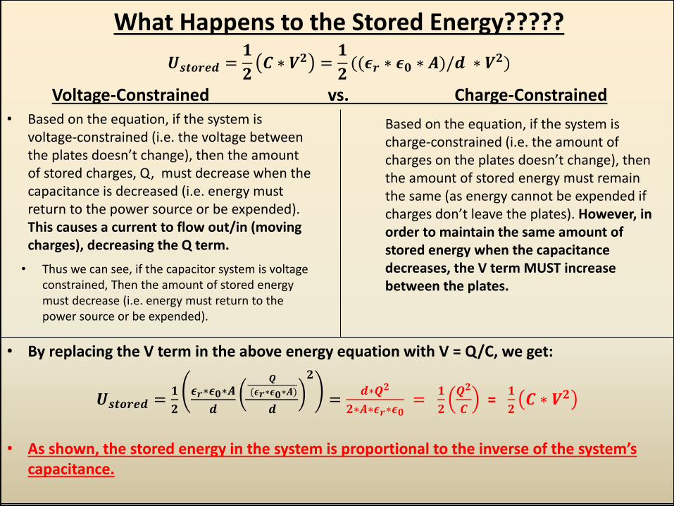
What Happens to the Stored Energy?????
𝑼𝒔𝒕𝒐𝒓𝒆𝒅 =𝟏
𝟐𝑪 ∗ 𝑽𝟐 =
𝟏
𝟐((𝝐𝒓 ∗ 𝝐𝟎 ∗ 𝑨)/𝒅 ∗ 𝑽𝟐)
Voltage-Constrained vs. Charge-Constrained • Based on the equation, if the system is
voltage-constrained (i.e. the voltage between the plates doesn’t change), then the amount of stored charges, Q, must decrease when the capacitance is decreased (i.e. energy must return to the power source or be expended). This causes a current to flow out/in (moving charges), decreasing the Q term.
Based on the equation, if the system is charge-constrained (i.e. the amount of charges on the plates doesn’t change), then the amount of stored energy must remain the same (as energy cannot be expended if charges don’t leave the plates). However, in order to maintain the same amount of stored energy when the capacitance decreases, the V term MUST increase between the plates.
• By replacing the V term in the above energy equation with V = Q/C, we get:
𝑼𝒔𝒕𝒐𝒓𝒆𝒅 =𝟏
𝟐
𝝐𝒓∗𝝐𝟎∗𝑨
𝒅
𝑸
(𝝐𝒓∗𝝐𝟎∗𝑨)
𝒅
𝟐
=𝒅∗𝑸𝟐
𝟐∗𝑨∗𝝐𝒓∗𝝐𝟎 =
𝟏
𝟐
𝑸𝟐
𝑪 =
𝟏
𝟐𝑪 ∗ 𝑽𝟐
• As shown, the stored energy in the system is proportional to the inverse of the system’s
capacitance.
• Thus we can see, if the capacitor system is voltage constrained, Then the amount of stored energy must decrease (i.e. energy must return to the power source or be expended).
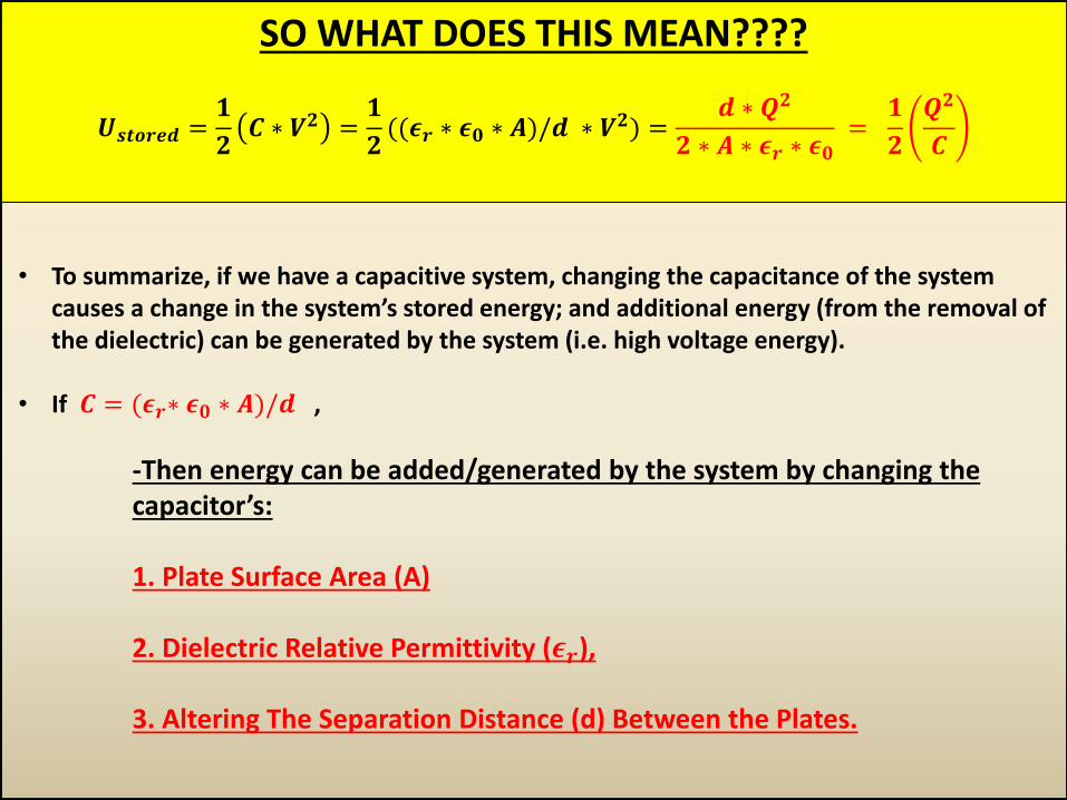
SO WHAT DOES THIS MEAN????
𝑼𝒔𝒕𝒐𝒓𝒆𝒅 =𝟏
𝟐𝑪 ∗ 𝑽𝟐 =
𝟏
𝟐((𝝐𝒓 ∗ 𝝐𝟎 ∗ 𝑨)/𝒅 ∗ 𝑽𝟐) =
𝒅 ∗ 𝑸𝟐
𝟐 ∗ 𝑨 ∗ 𝝐𝒓 ∗ 𝝐𝟎 =
𝟏
𝟐
𝑸𝟐
𝑪
• To summarize, if we have a capacitive system, changing the capacitance of the system causes a change in the system’s stored energy; and additional energy (from the removal of the dielectric) can be generated by the system (i.e. high voltage energy).
• If 𝑪 = (𝝐𝒓∗ 𝝐𝟎 ∗ 𝑨)/𝒅 ,
-Then energy can be added/generated by the system by changing the capacitor’s: 1. Plate Surface Area (A)
2. Dielectric Relative Permittivity (𝝐𝒓), 3. Altering The Separation Distance (d) Between the Plates.
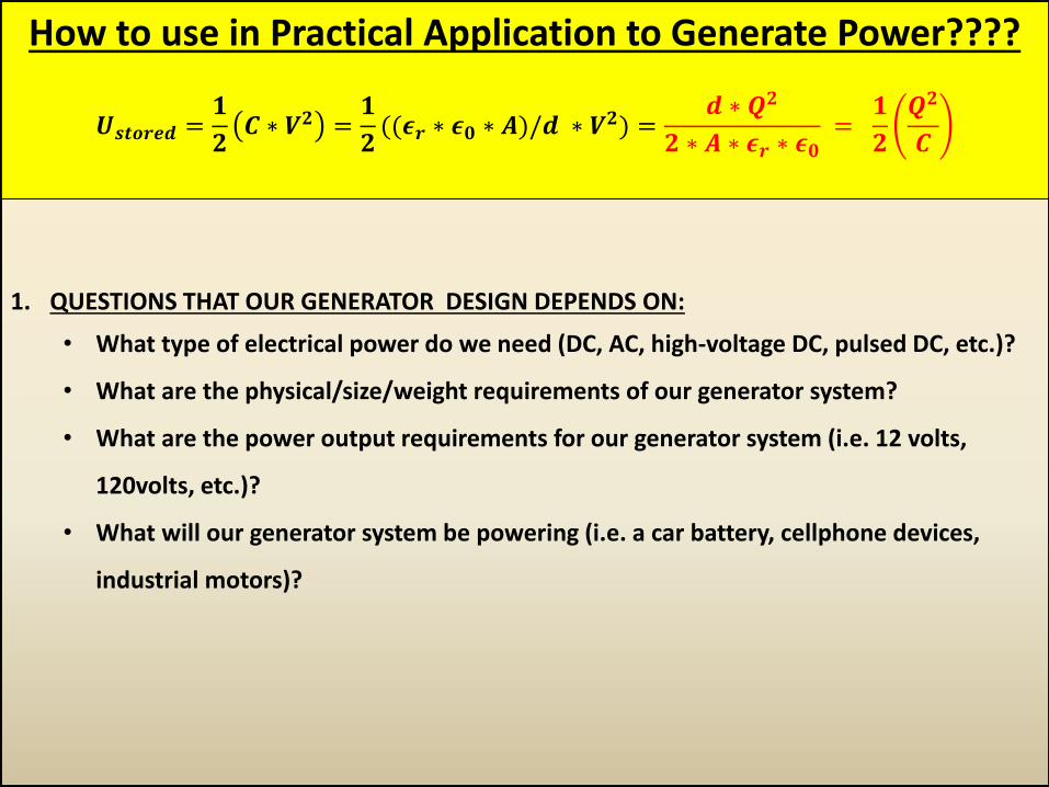
How to use in Practical Application to Generate Power????
𝑼𝒔𝒕𝒐𝒓𝒆𝒅 =𝟏
𝟐𝑪 ∗ 𝑽𝟐 =
𝟏
𝟐((𝝐𝒓 ∗ 𝝐𝟎 ∗ 𝑨)/𝒅 ∗ 𝑽𝟐) =
𝒅 ∗ 𝑸𝟐
𝟐 ∗ 𝑨 ∗ 𝝐𝒓 ∗ 𝝐𝟎 =
𝟏
𝟐
𝑸𝟐
𝑪
1. QUESTIONS THAT OUR GENERATOR DESIGN DEPENDS ON:
• What type of electrical power do we need (DC, AC, high-voltage DC, pulsed DC, etc.)?
• What are the physical/size/weight requirements of our generator system?
• What are the power output requirements for our generator system (i.e. 12 volts,
120volts, etc.)?
• What will our generator system be powering (i.e. a car battery, cellphone devices,
industrial motors)?
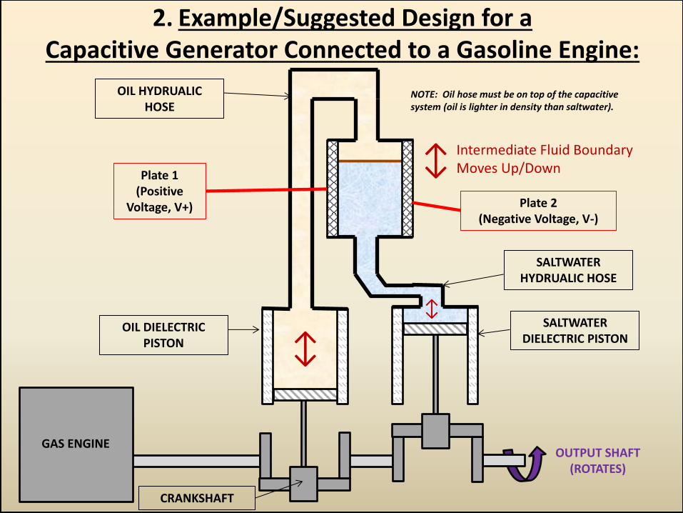
2. Example/Suggested Design for a Capacitive Generator Connected to a Gasoline Engine:
↕ Plate 1
(Positive Voltage, V+) Plate 2
(Negative Voltage, V-)
GAS ENGINE OUTPUT SHAFT
(ROTATES)
CRANKSHAFT
SALTWATER HYDRUALIC HOSE
Intermediate Fluid Boundary Moves Up/Down
NOTE: Oil hose must be on top of the capacitive system (oil is lighter in density than saltwater).
↕
↕
OIL HYDRUALIC HOSE
SALTWATER DIELECTRIC PISTON
OIL DIELECTRIC PISTON
2a. CAPACITOR DETAILS (IN-DEPTH) 1:
• WHY SALTWATER???? o When saltwater is used as a fluid dielectric medium (depending on its salt
concentration) it acts like a liquid metal, due to the dissolved ions present in it.
This means that it instantly transfers electrostatic fields from one plate to the other. Also water, itself, has a high dielectric permittivity (𝝐𝒓), since it is a bi-polar fluid. This would allow for larger changes in capacitance.
This parameter changes the “separation distance” (d) between the plates by instantly transferring charges from one plate to the other.
• WHY OIL????
o Oil presents a nice secondary dielectric medium fluid because it has a relatively low relative permittivity (means larger changes on capacitance = more power) & its mass density is significantly lower than that of saltwater (so the fluids will remain separated, when positioned vertically).
o Oil does not have ions dissolved in it and will act as an insulator.
This parameter will maximize the change in capacitance that can be achieved by increasing the separation distance (d) and lowering the relative permittivity of the dielectric medium (𝛜𝐫) between the plates.
2a. CAPACITOR DETAILS (IN-DEPTH) 2:
Plate 1 (Positive
Voltage, V+)
Plate 2 (Negative Voltage, V-)
Intermediate Fluid Boundary Moves Up/Down ↕
SALTWATER
OIL
Mylar Film (needed to avoid any high-voltage electrical discharge,
has a high dielectric strength per unit thickness)
Saltwater (effects ϵr & d):
1. Has a high relative permittivity (𝝐𝒓).
2. Acts as a liquid metal and makes separation distance (d) very small btw. the plates.
Oil (effects ϵr & d):
1. Has a low relative permittivity (𝝐𝒓).
2. Acts as an insulator and makes separation distance (d) larger btw. the plates.
2a. CAPACITOR DETAILS (IN-DEPTH) 2:
How To Does It Make Electrical Energy?: • When the salt water fills up the space between the capacitive plates, the effective
separation distance (d) between them is small (dsmall) and the relative permittivity of the salt water is high (𝝐𝒓high). A voltage (V) must be applied between the plates.
• This means the Capacitance value (C) for the system is large:
𝑪𝒍𝒂𝒓𝒈𝒆 = (𝝐𝒓𝒉𝒊𝒈𝒉∗ 𝝐𝟎 ∗ 𝑨)/𝒅𝒔𝒎𝒂𝒍𝒍
• Thus, if the C value is large, the stored energy in the system must be large as well, based on:
𝑼𝒔𝒕𝒐𝒓𝒆𝒅𝑳𝑨𝑹𝑮𝑬 =𝟏
𝟐𝑪𝑳𝑨𝑹𝑮𝑬 ∗ 𝑽𝟐
• When the oil fills up the space between the capacitive plates, the effective separation distance (d) between them becomes large (dlarge) and the relative permittivity of the oil is low (𝝐𝒓low).
• This means the Capacitance value for the system is small:
𝑪𝒔𝒎𝒂𝒍𝒍 = (𝝐𝒓𝒍𝒐𝒘∗ 𝝐𝟎 ∗ 𝑨)/𝒅𝒍𝒂𝒓𝒈𝒆
• Thus, if the C value is small, the stored energy in the system must be small as well, based on:
𝑼𝒔𝒕𝒐𝒓𝒆𝒅𝑺𝑴𝑨𝑳𝑳 =𝟏
𝟐𝑪𝑺𝑴𝑨𝑳𝑳 ∗ 𝑽𝟐
2a. CAPACITOR DETAILS (IN-DEPTH) 3: How To Does It Make Electrical Energy? Continued: • The change in the capacitance value (ΔC), creates a change in the energy stored in the system (∆𝑈𝑠𝑡𝑜𝑟𝑒𝑑). The equations for this are
provided (we will assume voltage is constant):
∆𝑼𝒔𝒕𝒐𝒓𝒆𝒅 =𝟏
𝟐∆𝑪 ∗ 𝑽𝟐
𝑷𝒔𝒕𝒐𝒓𝒆𝒅 =𝒅𝑼𝒔𝒕𝒐𝒓𝒆𝒅
𝒅𝒕=
𝟏
𝟐𝑽𝟐 ∗
𝒅𝑪
𝒅𝒕∗ 𝟐 ∗
𝒅𝑽
𝒅𝒕∗ 𝑪 =
𝟏
𝟐𝑽𝟐 ∗
𝒅𝑪
𝒅𝒕
How a Practical Application Works? • Circuit Schematic:
• The Variable Capacitor System works as an Electrical Charge Pump. • As the saltwater is pushed out (by the oil) of the capacitor, the mechanical work (W = F*d) done by the pistons
(pushing the saltwater) is turned into electrical power by the variable capacitor, in the form of increased voltage. As the voltage raises between the capacitor plates, it eventually becomes greater then the battery’s applied voltage. The difference in voltage levels causes a current to flow into the battery. The current flow, then causes the battery’s voltage to rise to the same level as the variable capacitor.
• When the capacitor is reaches the same voltage level as the battery, the charge pumping process stops.. When the piston begin to push the oil out (moving saltwater in), the capacitance of the system increases and draw more charges (at the same voltage as the battery) into the variable capacitor system.
• This process is then repeated over and over until the desired energy level in the battery is achieved.
• This process is known as “Charge-Pumping”, as charges (initially supplied by the battery) are raised in voltage level and flow back into the battery (increasing the battery’s overall stored energy).
Battery (Supplies Initial
Voltage to Charge the Variable
Capacitor System)
Variable Capacitor
System
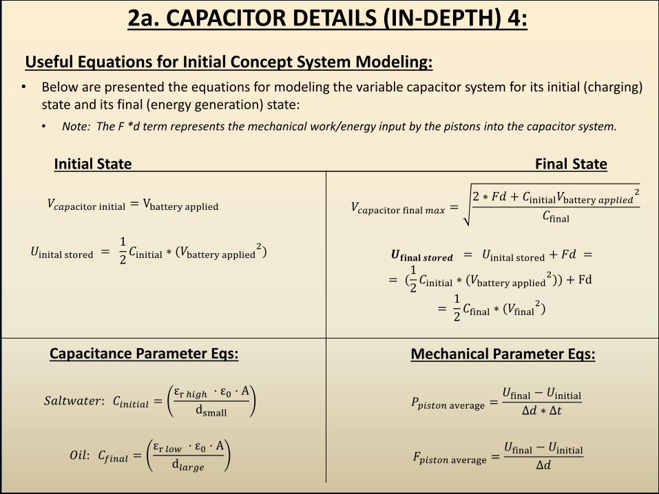
𝑈inital stored = 1
2𝐶initial ∗ (𝑉battery applied
2) 𝑼𝐟𝐢𝐧𝐚𝐥 𝒔𝒕𝒐𝒓𝒆𝒅 = 𝑈inital stored + 𝐹𝑑 =
= (1
2𝐶initial ∗ (𝑉battery applied
2)) + Fd
= 1
2𝐶final ∗ (𝑉final
2)
𝑉𝑐𝑎𝑝acitor final 𝑚𝑎𝑥 =2 ∗ 𝐹𝑑 + 𝐶initial𝑉battery 𝑎𝑝𝑝𝑙𝑖𝑒𝑑
2
𝐶final 𝑉𝑐𝑎𝑝acitor initial = Vbattery applied
𝐹𝑝𝑖𝑠𝑡𝑜𝑛 average =𝑈final − 𝑈initial
Δ𝑑
𝑃𝑝𝑖𝑠𝑡𝑜𝑛 average =𝑈final − 𝑈initial
Δ𝑑 ∗ Δ𝑡 𝑆𝑎𝑙𝑡𝑤𝑎𝑡𝑒𝑟: 𝐶𝑖𝑛𝑖𝑡𝑖𝑎𝑙 =
εr ℎ𝑖𝑔ℎ · ε0 · A
dsmall
𝑂𝑖𝑙: 𝐶𝑓𝑖𝑛𝑎𝑙 =εr 𝑙𝑜𝑤 · ε0 · A
d𝑙𝑎𝑟𝑔𝑒
2a. CAPACITOR DETAILS (IN-DEPTH) 4:
Useful Equations for Initial Concept System Modeling:
• Below are presented the equations for modeling the variable capacitor system for its initial (charging) state and its final (energy generation) state:
• Note: The F *d term represents the mechanical work/energy input by the pistons into the capacitor system.
Initial State Final State
Capacitance Parameter Eqs: Mechanical Parameter Eqs:
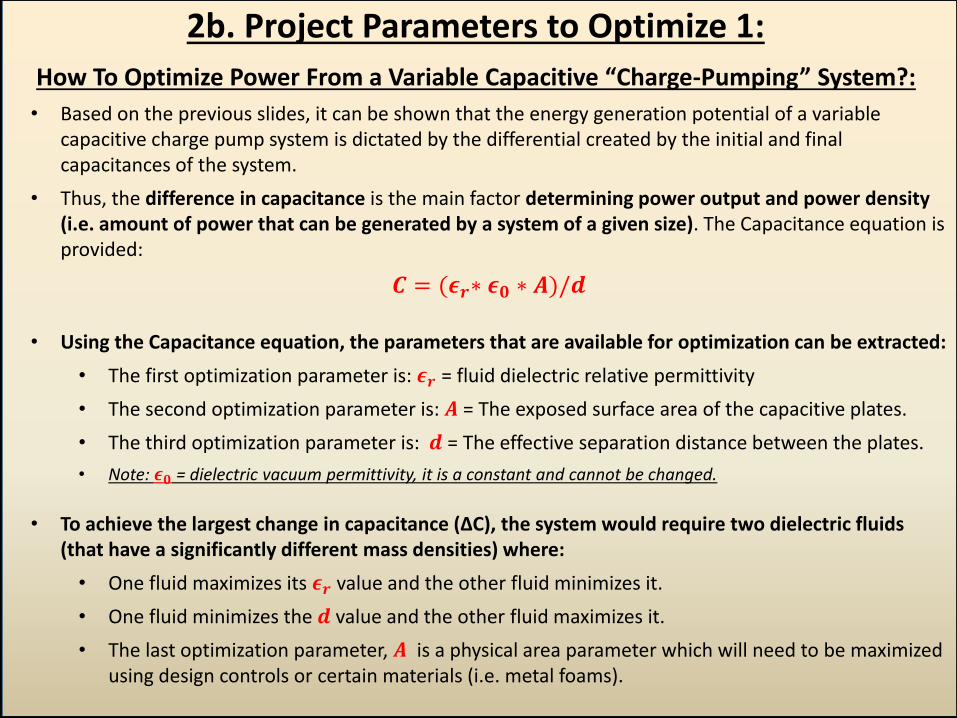
2b. Project Parameters to Optimize 1:
How To Optimize Power From a Variable Capacitive “Charge-Pumping” System?:
• Based on the previous slides, it can be shown that the energy generation potential of a variable capacitive charge pump system is dictated by the differential created by the initial and final capacitances of the system.
• Thus, the difference in capacitance is the main factor determining power output and power density (i.e. amount of power that can be generated by a system of a given size). The Capacitance equation is provided:
𝑪 = (𝝐𝒓∗ 𝝐𝟎 ∗ 𝑨)/𝒅
• Using the Capacitance equation, the parameters that are available for optimization can be extracted:
• The first optimization parameter is: 𝝐𝒓 = fluid dielectric relative permittivity
• The second optimization parameter is: 𝑨 = The exposed surface area of the capacitive plates.
• The third optimization parameter is: 𝒅 = The effective separation distance between the plates.
• Note: 𝝐𝟎 = dielectric vacuum permittivity, it is a constant and cannot be changed.
• To achieve the largest change in capacitance (ΔC), the system would require two dielectric fluids (that have a significantly different mass densities) where:
• One fluid maximizes its 𝝐𝒓 value and the other fluid minimizes it.
• One fluid minimizes the 𝒅 value and the other fluid maximizes it.
• The last optimization parameter, 𝑨 is a physical area parameter which will need to be maximized using design controls or certain materials (i.e. metal foams).
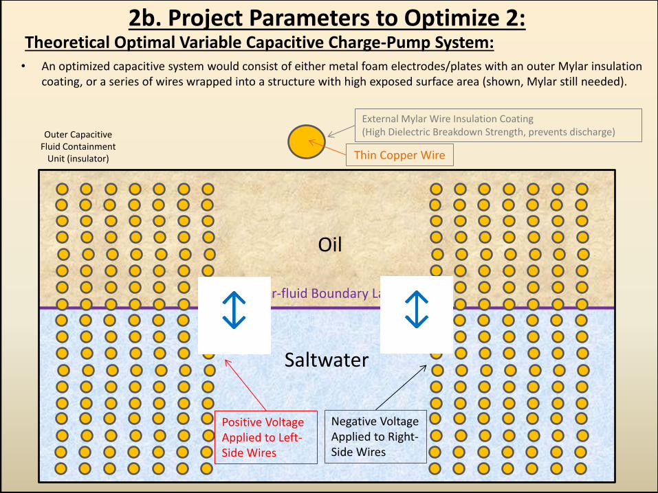
2b. Project Parameters to Optimize 2: Theoretical Optimal Variable Capacitive Charge-Pump System: • An optimized capacitive system would consist of either metal foam electrodes/plates with an outer Mylar insulation
coating, or a series of wires wrapped into a structure with high exposed surface area (shown, Mylar still needed).
External Mylar Wire Insulation Coating (High Dielectric Breakdown Strength, prevents discharge)
Thin Copper Wire
Oil
Saltwater
Positive Voltage Applied to Left-Side Wires
Negative Voltage Applied to Right-Side Wires
Inter-fluid Boundary Layer
Outer Capacitive Fluid Containment
Unit (insulator)
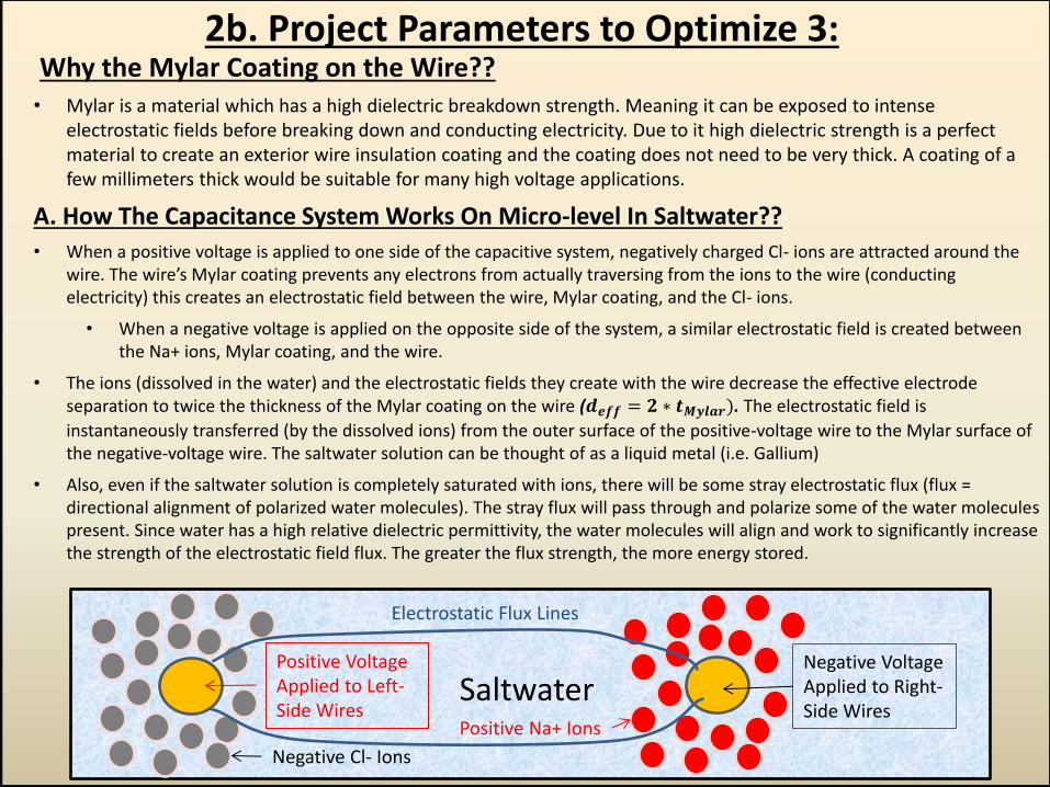
2b. Project Parameters to Optimize 3: Why the Mylar Coating on the Wire?? • Mylar is a material which has a high dielectric breakdown strength. Meaning it can be exposed to intense
electrostatic fields before breaking down and conducting electricity. Due to it high dielectric strength is a perfect material to create an exterior wire insulation coating and the coating does not need to be very thick. A coating of a few millimeters thick would be suitable for many high voltage applications.
A. How The Capacitance System Works On Micro-level In Saltwater??
• When a positive voltage is applied to one side of the capacitive system, negatively charged Cl- ions are attracted around the wire. The wire’s Mylar coating prevents any electrons from actually traversing from the ions to the wire (conducting electricity) this creates an electrostatic field between the wire, Mylar coating, and the Cl- ions.
• When a negative voltage is applied on the opposite side of the system, a similar electrostatic field is created between the Na+ ions, Mylar coating, and the wire.
• The ions (dissolved in the water) and the electrostatic fields they create with the wire decrease the effective electrode separation to twice the thickness of the Mylar coating on the wire (𝒅𝒆𝒇𝒇 = 𝟐 ∗ 𝒕𝑴𝒚𝒍𝒂𝒓). The electrostatic field is
instantaneously transferred (by the dissolved ions) from the outer surface of the positive-voltage wire to the Mylar surface of the negative-voltage wire. The saltwater solution can be thought of as a liquid metal (i.e. Gallium)
• Also, even if the saltwater solution is completely saturated with ions, there will be some stray electrostatic flux (flux = directional alignment of polarized water molecules). The stray flux will pass through and polarize some of the water molecules present. Since water has a high relative dielectric permittivity, the water molecules will align and work to significantly increase the strength of the electrostatic field flux. The greater the flux strength, the more energy stored.
Positive Voltage Applied to Left-Side Wires
Negative Voltage Applied to Right-Side Wires
Positive Na+ Ions
Negative Cl- Ions
Saltwater
Electrostatic Flux Lines
2b. Project Parameters to Optimize 3:
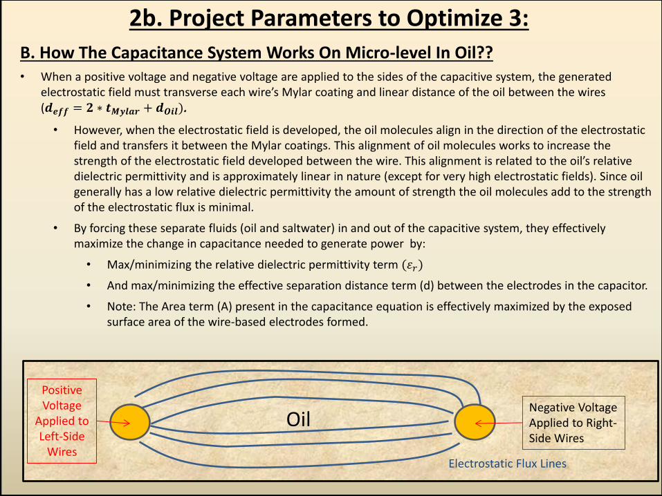
B. How The Capacitance System Works On Micro-level In Oil?? • When a positive voltage and negative voltage are applied to the sides of the capacitive system, the generated
electrostatic field must transverse each wire’s Mylar coating and linear distance of the oil between the wires (𝒅𝒆𝒇𝒇 = 𝟐 ∗ 𝒕𝑴𝒚𝒍𝒂𝒓 + 𝒅𝑶𝒊𝒍).
• However, when the electrostatic field is developed, the oil molecules align in the direction of the electrostatic field and transfers it between the Mylar coatings. This alignment of oil molecules works to increase the strength of the electrostatic field developed between the wire. This alignment is related to the oil’s relative dielectric permittivity and is approximately linear in nature (except for very high electrostatic fields). Since oil generally has a low relative dielectric permittivity the amount of strength the oil molecules add to the strength of the electrostatic flux is minimal.
• By forcing these separate fluids (oil and saltwater) in and out of the capacitive system, they effectively maximize the change in capacitance needed to generate power by:
• Max/minimizing the relative dielectric permittivity term (𝜀𝑟)
• And max/minimizing the effective separation distance term (d) between the electrodes in the capacitor.
• Note: The Area term (A) present in the capacitance equation is effectively maximized by the exposed surface area of the wire-based electrodes formed.
Positive Voltage
Applied to Left-Side
Wires
Negative Voltage Applied to Right-Side Wires
Oil
Electrostatic Flux Lines