DTS-P-0065 A5 att 1 - Lite-On Semiconductor Corp. … Plane 0.25 BSC θ 0 8 LT431 ADJUSTABLE...
13
LT431 ADJUSTABLE PRECISIONSHUNT REGULATION 1 of 13 www.liteonsemi.com LT431 Rev. 4.5 2014/8/27 General Description The LT431 is a low voltage three terminal adjustable shunt regulator with a guaranteed thermal stability over applicable temperature ranges. The output voltage can be set to any value between 2.495V (VREF) to 36V with two external resistors (see application circuit). The high precise Reference voltage tolerance is ±0.4% and ±1.0% by LT431. This device has a typical output impedance of 0.2Ω. Active output circuitry provides a very sharp turn on characteristic, making this device excel lent replacement for Zener diodes in many applications.. Features Precision reference voltage : LT431O : 2.495V±0.4% LT431N : 2.495V±1.0% Adjustable output voltage is VREF to 36V Sink current capability is 200mA Low dynamic output impedance is 0.2Ω (typ.) Minimum Cathode current for regulation is 0.2mA (typ.) Plastic material has UL flammability classification 94V-0 Applications Switching Mode Power Supply Voltage Reference Application Block Diagram & Symbol Please be aware that an Important Notice concerning availability, disclaimers, and use in critical applications of LSC products is at the end of this document.
Transcript of DTS-P-0065 A5 att 1 - Lite-On Semiconductor Corp. … Plane 0.25 BSC θ 0 8 LT431 ADJUSTABLE...
LT431 ADJUSTABLE
PRECISIONSHUNT REGULATION
1 of 13
www.liteonsemi.com
LT431 Rev. 4.5 2014/8/27
General Description
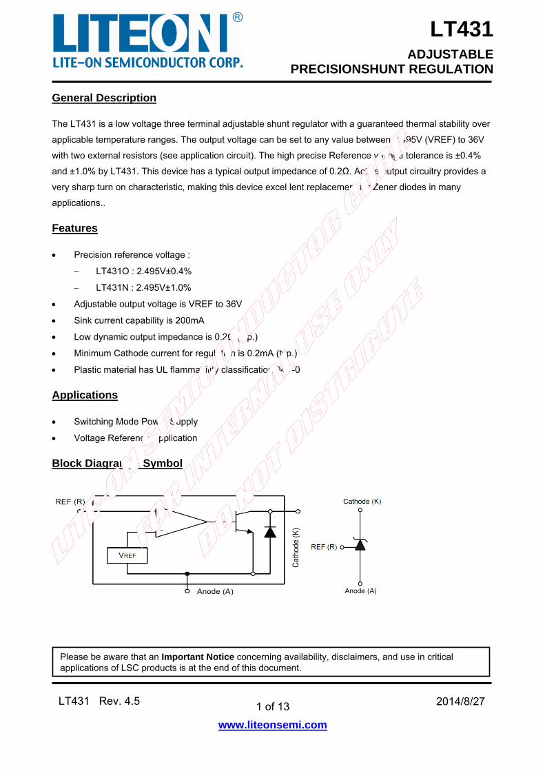
The LT431 is a low voltage three terminal adjustable shunt regulator with a guaranteed thermal stability over
applicable temperature ranges. The output voltage can be set to any value between 2.495V (VREF) to 36V
with two external resistors (see application circuit). The high precise Reference voltage tolerance is ±0.4%
and ±1.0% by LT431. This device has a typical output impedance of 0.2Ω. Active output circuitry provides a
very sharp turn on characteristic, making this device excel lent replacement for Zener diodes in many
applications..
Features
Precision reference voltage :
LT431O : 2.495V±0.4%
LT431N : 2.495V±1.0%
Adjustable output voltage is VREF to 36V
Sink current capability is 200mA
Low dynamic output impedance is 0.2Ω (typ.)
Minimum Cathode current for regulation is 0.2mA (typ.)
Plastic material has UL flammability classification 94V-0
Applications
Switching Mode Power Supply
Voltage Reference Application
Block Diagram & Symbol
Please be aware that an Important Notice concerning availability, disclaimers, and use in critical applications of LSC products is at the end of this document.
LT431 ADJUSTABLE
PRECISIONSHUNT REGULATION
2 of 13
www.liteonsemi.com
LT431 Rev. 4.5 2014/8/27
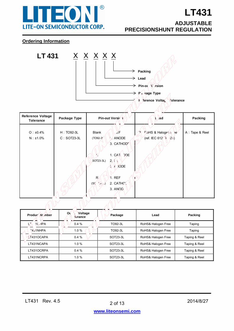
Ordering Information
O : ±0.4% H : TO92-3L Blank 1. REF P : RoHS & Halogen Free A : Tape & Reel
N : ±1.0% C : SOT23-3L (TO92-3L) 2. ANODE (ref. IEC 61249-2-21)
3. CATHODE
A 1. CATHODE
(SOT23-3L) 2. REF
3. ANODE
R 1. REF
(SOT23-3L) 2. CATHODE
3. ANODE
Reference VoltageTolerance
Package Type Pin-out Version Lead Packing
LT 431
Pin-out Version
Package Type
Reference Voltage Tolerance
X X X X
Lead
X
Packing
Product Number Output Voltage
Tolerance Package Lead Packing
LT431OHPA 0.4 % TO92-3L RoHS& Halogen Free Taping
LT431NHPA 1.0 % TO92-3L RoHS& Halogen Free Taping
LT431OCAPA 0.4 % SOT23-3L RoHS& Halogen Free Taping & Reel
LT431NCAPA 1.0 % SOT23-3L RoHS& Halogen Free Taping & Reel
LT431OCRPA 0.4 % SOT23-3L RoHS& Halogen Free Taping & Reel
LT431NCRPA 1.0 % SOT23-3L RoHS& Halogen Free Taping & Reel
LT431 ADJUSTABLE
PRECISIONSHUNT REGULATION
3 of 13
www.liteonsemi.com
LT431 Rev. 4.5 2014/8/27
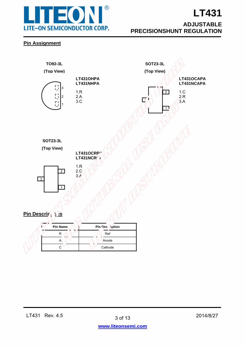
Pin Assignment
Pin Descriptions
Pin Name Pin Description
R Ref
A Anode
C Cathode
SOT23-3L
(Top View)
3
2
1
LT431OHPA LT431NHPA
1.R 2.A 3.C
LT431OCRPA LT431NCRPA
1.R 2.C 3.A
SOT23-3L
(Top View)
LT431OCAPA LT431NCAPA
1.C 2.R 3.A
2
1
3
2
1
3
TO92-3L
(Top View)
LT431 ADJUSTABLE
PRECISIONSHUNT REGULATION
4 of 13
www.liteonsemi.com
LT431 Rev. 4.5 2014/8/27
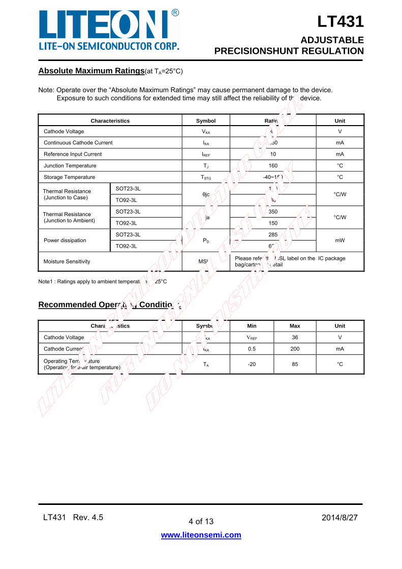
Absolute Maximum Ratings(at TA=25°C)
Note: Operate over the “Absolute Maximum Ratings” may cause permanent damage to the device. Exposure to such conditions for extended time may still affect the reliability of the device.
Characteristics Symbol Rating Unit
Cathode Voltage VKA 40 V
Continuous Cathode Current IKA 250 mA
Reference Input Current IREF 10 mA
Junction Temperature TJ 160 °C
Storage Temperature TSTG -40~150 °C
Thermal Resistance (Junction to Case)
SOT23-3L θjc
110 °C/W
TO92-3L 80
Thermal Resistance (Junction to Ambient)
SOT23-3L θja
350 °C/W
TO92-3L 150
Power dissipation SOT23-3L
PD 285
mW TO92-3L 625
Moisture Sensitivity MSL Please refer the MSL label on the IC package bag/carton for detail
Note1 : Ratings apply to ambient temperature at 25°C
Recommended Operating Conditions
Characteristics Symbol Min Max Unit
Cathode Voltage VKA VREF 36 V
Cathode Current IKA 0.5 200 mA
Operating Temperature (Operating free-air temperature)
TA -20 85 °C
LT431 ADJUSTABLE
PRECISIONSHUNT REGULATION
5 of 13
www.liteonsemi.com
LT431 Rev. 4.5 2014/8/27
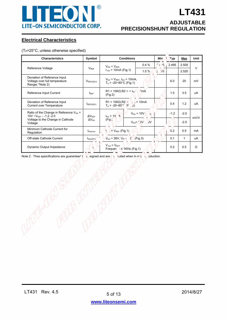
Electrical Characteristics
(TA=25°C, unless otherwise specified)
Characteristics Symbol Conditions Min Typ Max Unit
Reference Voltage VREF VKA = VREF,
I KA = 10mA (Fig.1)
0.4 % 2.485 2.495 2.505V
1.0 % 2.470 2.520
Deviation of Reference Input Voltage over full temperature Range( *Note 2)
VREF(DEV)VKA = VREF, IKA = 10mA, TA = -20~85°C (Fig.1)
6.0 20 mV
Reference Input Current IREF R1 = 10KΩ,R2 = ∞ IKA= 10mA (Fig.2)
1.5 3.5 uA
Deviation of Reference Input Current over Temperature
IREF(DEV)R1 = 10KΩ,R2 = ∞ IKA = 10mA TA = -20~85°C (Fig.2)
0.4 1.2 uA
Ratio of the Change in Reference VKA = 10V ~VREF - -1.2 -2.0 Voltage to the Change in Cathode Voltage
ΔVREF ΔVKA
IKA = 10mA (Fig.2)
VKA = 10V ~VREF -1.2 -2.0
mV/V
VKA= 36V ~10V -1 -2.0
Minimum Cathode Current for Regulation
IKA(min) VKA = VREF (Fig.1) 0.2 0.5 mA
Off-state Cathode Current IKA(OFF) VKA = 36V, VREF = 0V (Fig.3) 0.1 1 uA
Dynamic Output Impedance ZKA V KA = VREF Frequency ≤ 1KHz (Fig.1)
0.2 0.5 Ω
Note 2 : Thes speicifications are guaranteed by designed and are not tested when in mass-production.
LT431 ADJUSTABLE
PRECISIONSHUNT REGULATION
6 of 13
www.liteonsemi.com
LT431 Rev. 4.5 2014/8/27
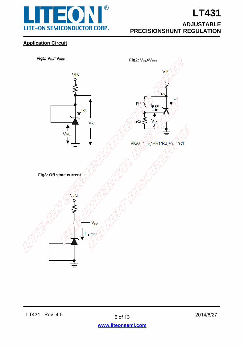
Application Circuit
Fig1: VKA=VREF Fig2: VKA>VREF
Fig3: Off state current
LT431 ADJUSTABLE
PRECISIONSHUNT REGULATION
7 of 13
www.liteonsemi.com
LT431 Rev. 4.5 2014/8/27
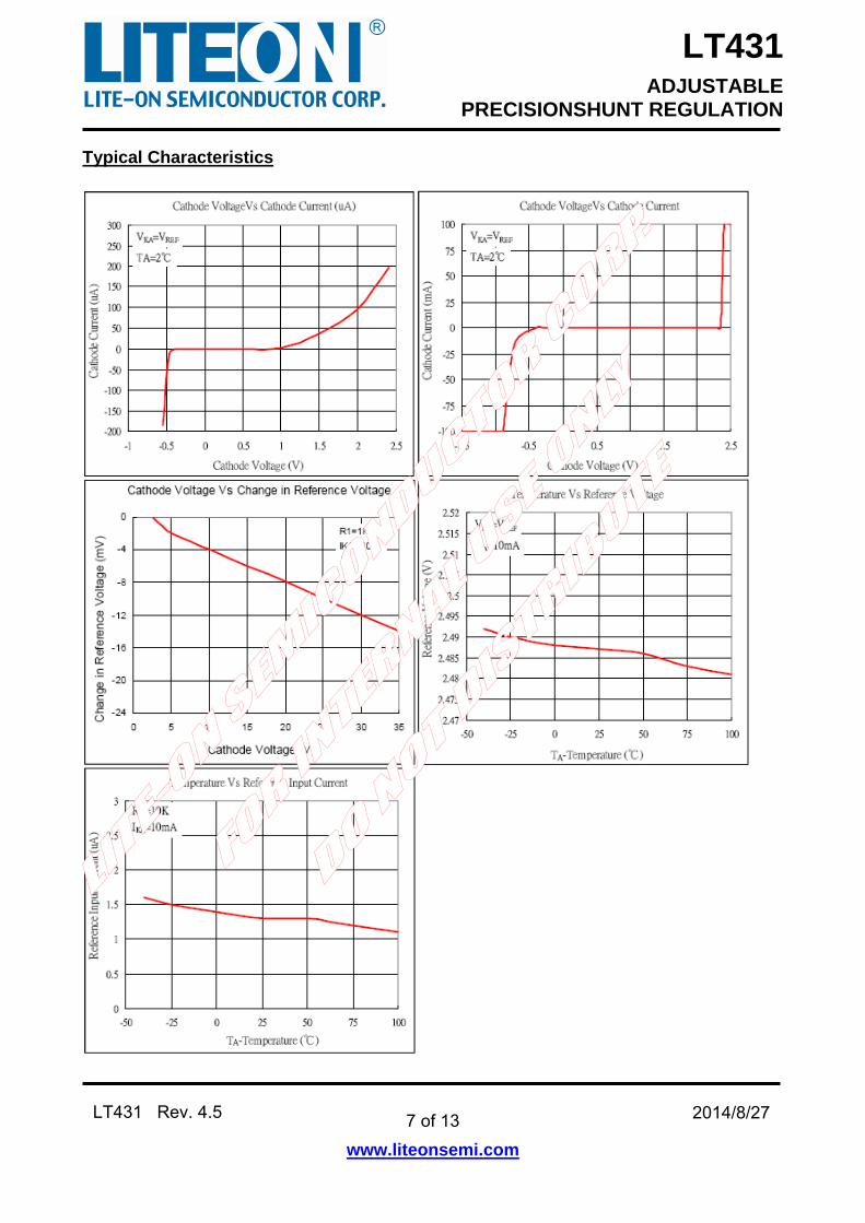
Typical Characteristics
LT431 ADJUSTABLE
PRECISIONSHUNT REGULATION
8 of 13
www.liteonsemi.com
LT431 Rev. 4.5 2014/8/27
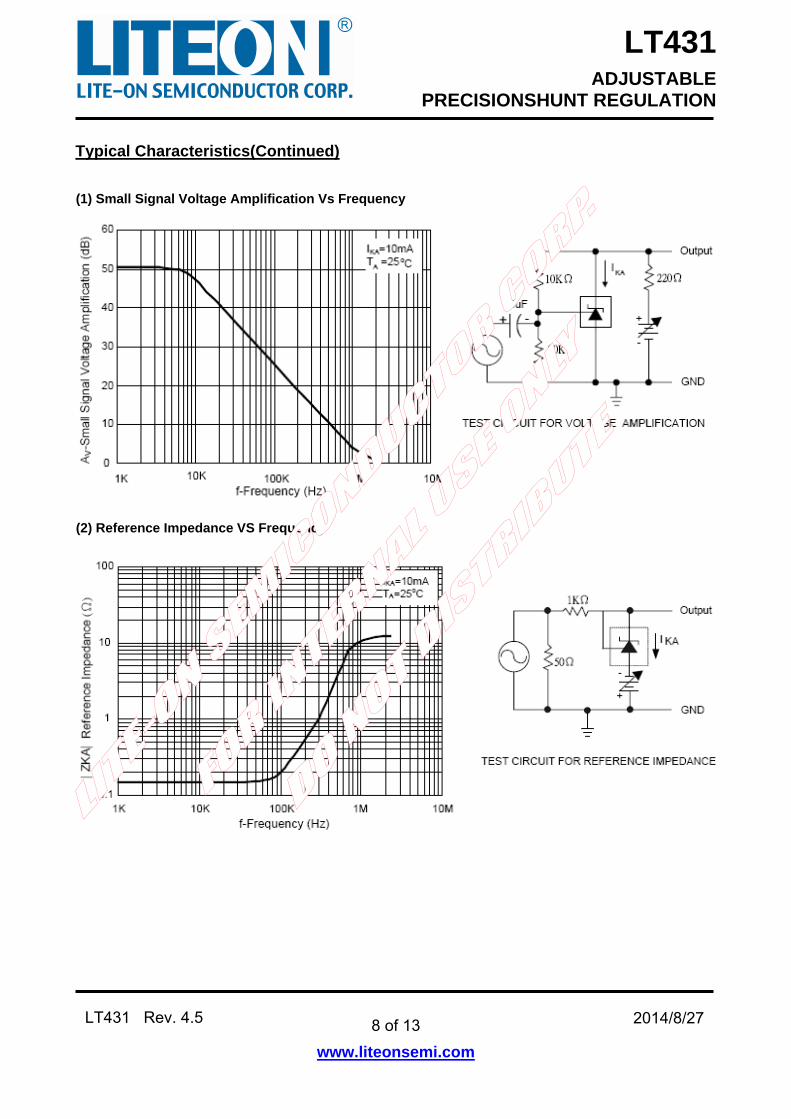
Typical Characteristics(Continued)
(1) Small Signal Voltage Amplification Vs Frequency
(2) Reference Impedance VS Frequency
LT431 ADJUSTABLE
PRECISIONSHUNT REGULATION
9 of 13
www.liteonsemi.com
LT431 Rev. 4.5 2014/8/27
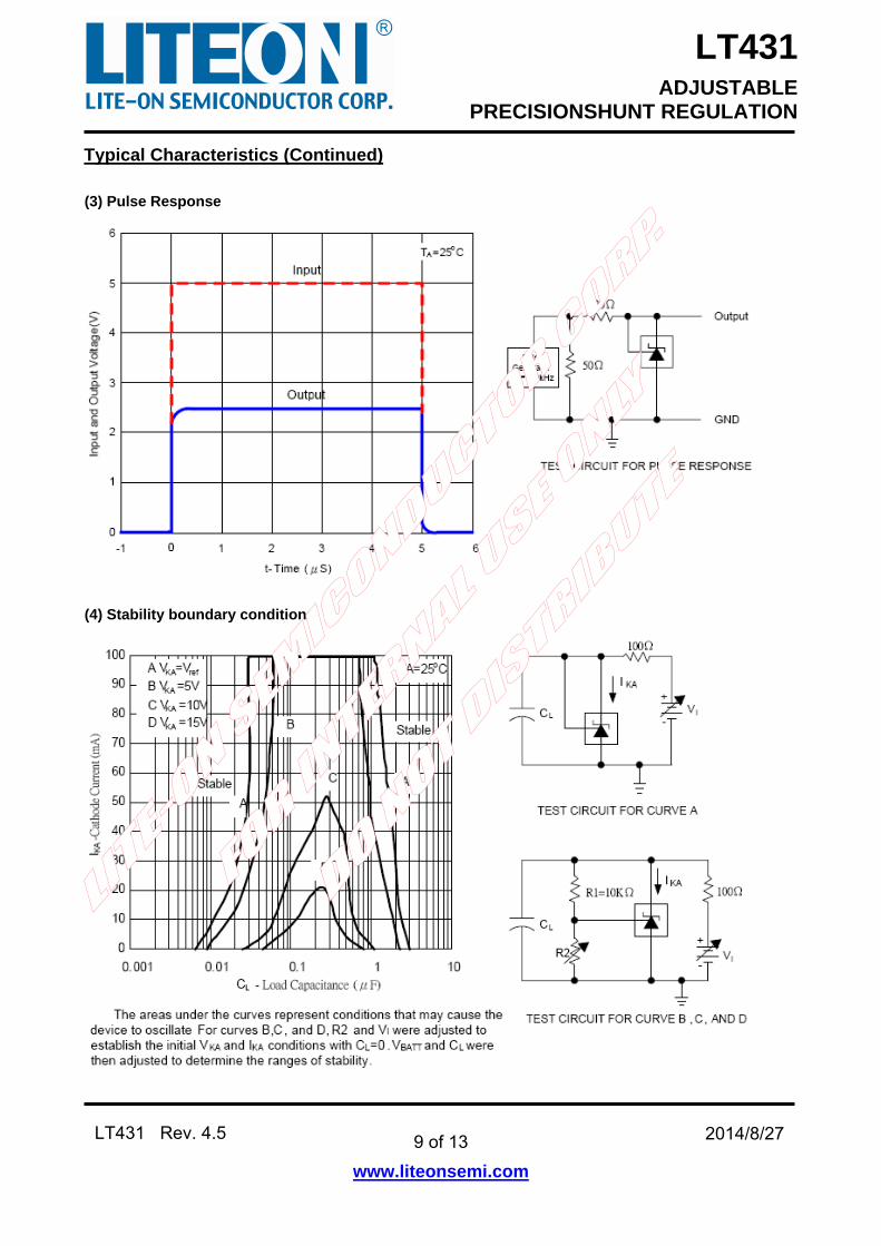
Typical Characteristics (Continued)
(3) Pulse Response
(4) Stability boundary conditions
LT431 ADJUSTABLE
PRECISIONSHUNT REGULATION
10 of 13
www.liteonsemi.com
LT431 Rev. 4.5 2014/8/27
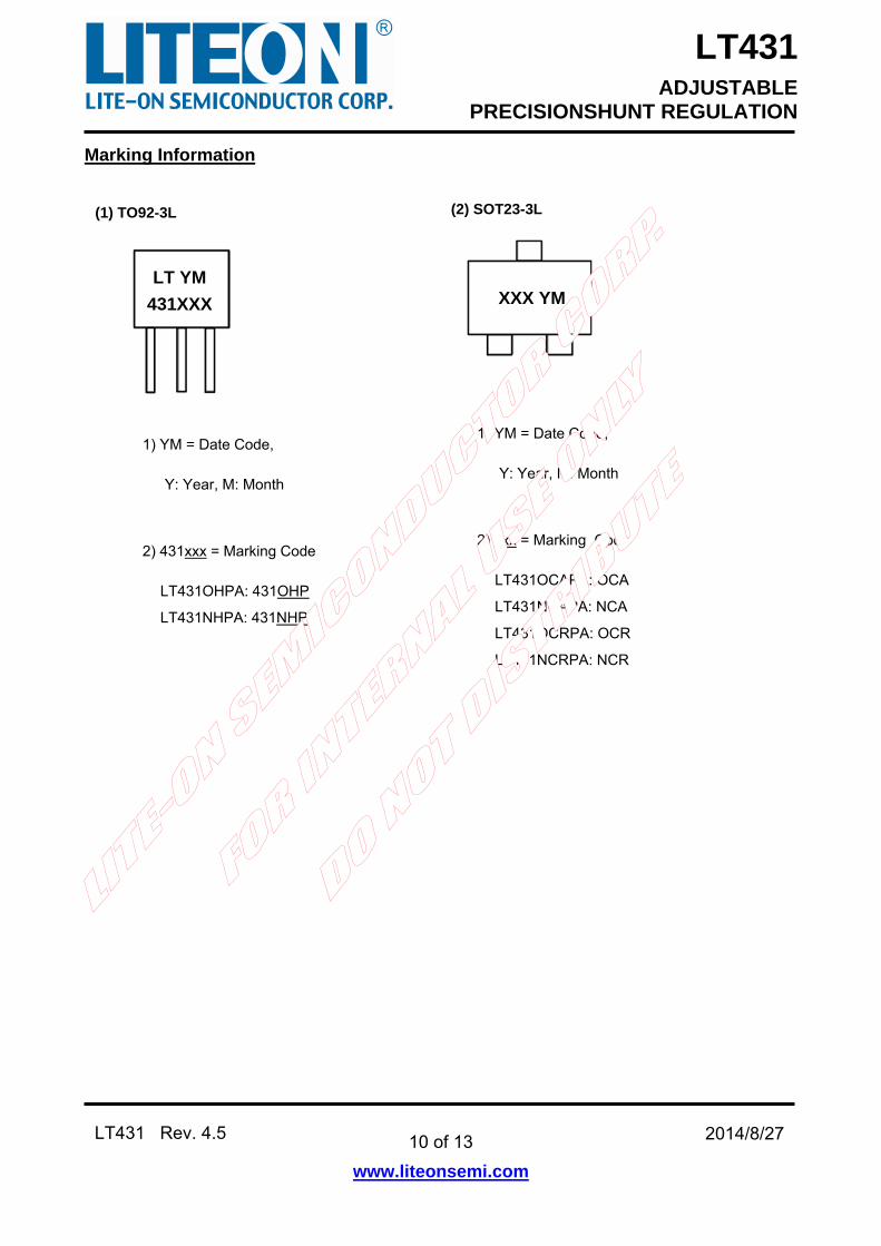
Marking Information
(2) SOT23-3L (1) TO92-3L
LT YM
431XXX
1) YM = Date Code,
Y: Year, M: Month
2) 431xxx = Marking Code
LT431OHPA: 431OHP
LT431NHPA: 431NHP
XXX YM
1) YM = Date Code,
Y: Year, M: Month
2) xxx = Marking Code
LT431OCAPA: OCA
LT431NCAPA: NCA
LT431OCRPA: OCR
LT431NCRPA: NCR
LT431 ADJUSTABLE
PRECISIONSHUNT REGULATION
11 of 13
www.liteonsemi.com
LT431 Rev. 4.5 2014/8/27
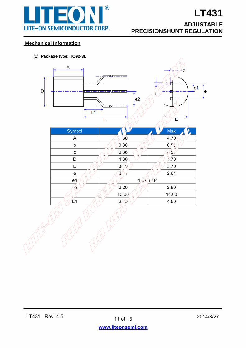
Mechanical Information
(1) Package type: TO92-3L
Symbol Min Max
A 4.30 4.70
b 0.38 0.55
c 0.36 0.51
D 4.30 4.70
E 3.30 3.70
e 2.44 2.64
e1 1.27 TYP
e2 2.20 2.80
L 13.00 14.00
L1 2.50 4.50
LT431 ADJUSTABLE
PRECISIONSHUNT REGULATION
12 of 13
www.liteonsemi.com
LT431 Rev. 4.5 2014/8/27
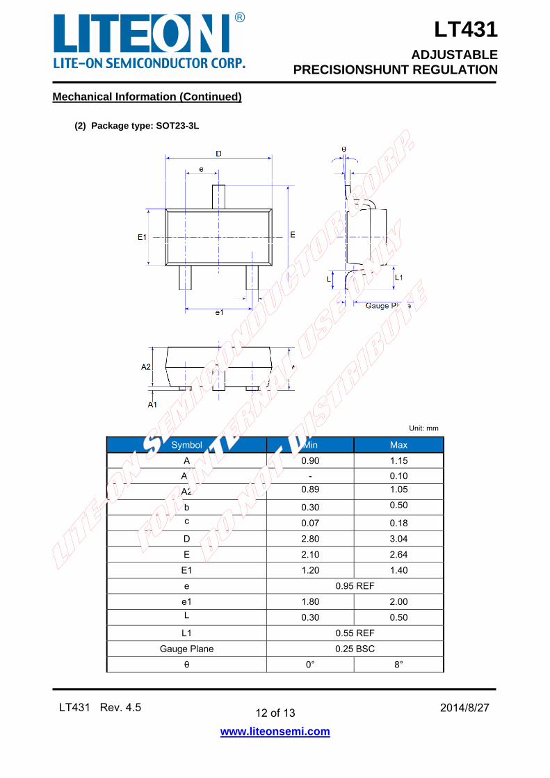
Mechanical Information (Continued)
(2) Package type: SOT23-3L
Unit: mm
Symbol Min Max
A 0.90 1.15
A1 - 0.10
A2 0.89 1.05
b 0.30 0.50
c 0.07 0.18
D 2.80 3.04
E 2.10 2.64
E1 1.20 1.40
e 0.95 REF
e1 1.80 2.00
L 0.30 0.50
L1 0.55 REF
Gauge Plane 0.25 BSC
θ 0° 8°
LT431 ADJUSTABLE
PRECISIONSHUNT REGULATION
13 of 13
www.liteonsemi.com
LT431 Rev. 4.5 2014/8/27
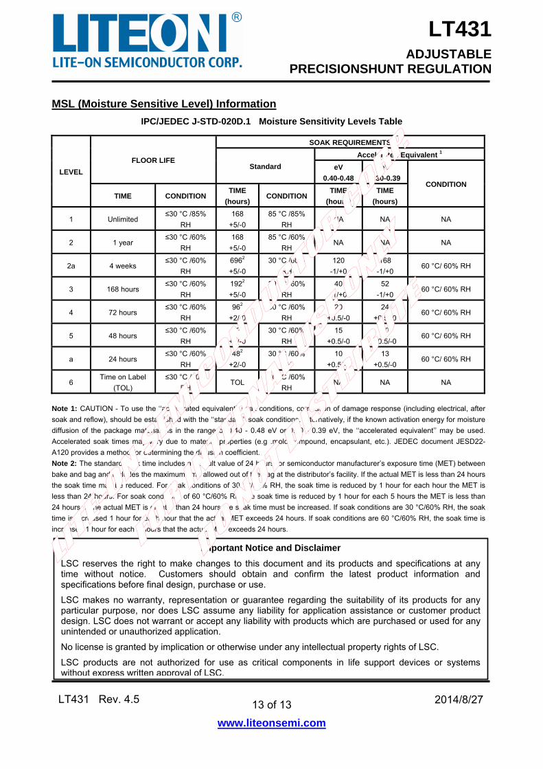
MSL (Moisture Sensitive Level) Information
IPC/JEDEC J-STD-020D.1 Moisture Sensitivity Levels Table
LEVEL
FLOOR LIFE
SOAK REQUIREMENTS
Standard
Accelerated Equivalent 1
eV
0.40-0.48
eV
0.30-0.39 CONDITION
TIME CONDITION TIME
(hours) CONDITION
TIME
(hours)
TIME
(hours)
1 Unlimited ≤30 °C /85%
RH
168
+5/-0
85 °C /85%
RH NA NA NA
2 1 year ≤30 °C /60%
RH
168
+5/-0
85 °C /60%
RH NA NA NA
2a 4 weeks ≤30 °C /60%
RH
6962
+5/-0
30 °C /60%
RH
120
-1/+0
168
-1/+0 60 °C/ 60% RH
3 168 hours ≤30 °C /60%
RH
1922
+5/-0
30 °C /60%
RH
40
-1/+0
52
-1/+0 60 °C/ 60% RH
4 72 hours ≤30 °C /60%
RH
962
+2/-0
30 °C /60%
RH
20
+0.5/-0
24
+0.5/-0 60 °C/ 60% RH
5 48 hours ≤30 °C /60%
RH
722
+2/-0
30 °C /60%
RH
15
+0.5/-0
20
+0.5/-0 60 °C/ 60% RH
a 24 hours ≤30 °C /60%
RH
482
+2/-0
30 °C /60%
RH
10
+0.5/-0
13
+0.5/-0 60 °C/ 60% RH
6 Time on Label
(TOL)
≤30 °C /60%
RH TOL
30 °C /60%
RH NA NA NA
Note 1: CAUTION - To use the ‘‘accelerated equivalent’’ soak conditions, correlation of damage response (including electrical, after
soak and reflow), should be established with the ‘‘standard’’ soak conditions. Alternatively, if the known activation energy for moisture
diffusion of the package materials is in the range of 0.40 - 0.48 eV or 0.30 - 0.39 eV, the ‘‘accelerated equivalent’’ may be used.
Accelerated soak times may vary due to material properties (e.g .mold compound, encapsulant, etc.). JEDEC document JESD22-
A120 provides a method for determining the diffusion coefficient.
Note 2: The standard soak time includes a default value of 24 hours for semiconductor manufacturer’s exposure time (MET) between
bake and bag and includes the maximum time allowed out of the bag at the distributor’s facility. If the actual MET is less than 24 hours
the soak time may be reduced. For soak conditions of 30 °C/60% RH, the soak time is reduced by 1 hour for each hour the MET is
less than 24 hours. For soak conditions of 60 °C/60% RH, the soak time is reduced by 1 hour for each 5 hours the MET is less than
24 hours. If the actual MET is greater than 24 hours the soak time must be increased. If soak conditions are 30 °C/60% RH, the soak
time is increased 1 hour for each hour that the actual MET exceeds 24 hours. If soak conditions are 60 °C/60% RH, the soak time is
increased 1 hour for each 5 hours that the actual MET exceeds 24 hours.
Important Notice and Disclaimer
LSC reserves the right to make changes to this document and its products and specifications at any time without notice. Customers should obtain and confirm the latest product information and specifications before final design, purchase or use.
LSC makes no warranty, representation or guarantee regarding the suitability of its products for any particular purpose, nor does LSC assume any liability for application assistance or customer product design. LSC does not warrant or accept any liability with products which are purchased or used for any unintended or unauthorized application.
No license is granted by implication or otherwise under any intellectual property rights of LSC.
LSC products are not authorized for use as critical components in life support devices or systems without express written approval of LSC.