Design and Implementation of a New Wireless Remote Control ...
9
Design and Implementation of a New Wireless Remote Control Cipher Lock System Based on Single Chip Microcomputer An Sha Haojing College of Shaanxi University of Science and Technology, Xi'an 712046, China Keywords: Single Chip Microcomputer, At89c52, Wireless Remote Control, Radio Frequency, Ook Modulation Abstract: This Paper Mainly Focused on the Theoretical and Practical Application of a New Wireless Remote Control System. This Article Mainly Includes the Following Content: According to the Requirements of the Project is Proposed to Scm as the Central Processor, the Short Distance Wireless Remote Control Technology and Electronic Password Lock System by Combining the Technology of Solution, Gives the Hardware Circuit Design and Software Structure Are Described in Detail in the System Hardware Circuit Design Elements and Structure as Well as the Software Design Points, and Give the Various Important Subroutine Flow Chart. in This Paper Presents a with Four Data Bits of the Encoding and Decoding Chip to Complete the 12 Data Transmission Design Method and Gives Details of the Design Method and Principle of That and the Specific Design of the Electric Jump At the Same Time, This Paper Presents a Unique Hardware Reset Circuit, Gives the Detailed System Anti Interference Measures and the System Energy Conservation Measure. in This Paper, the Design of the Circuit and Control Method is Applied to the Design of the Single Chip Microcomputer System, the Hardware and Software Are Also Practical and Universal. 1. Introduction With the Improvement of People's Life and the Strengthening of Security Awareness, Various Series of Safe Boxes Are Widely Used in People's Life and Work, So the Safety of the Lock System Becomes Very Important. Currently on the Market, the Lock of the Safe Deposit Box Has the Following Several Ways. One is the Mechanical Type of Password Lock, It Has the Advantages of Low Cost, Strong Anti-Interference Ability, But Also Has a Small Amount of Password, Poor Security, the Key is Easy to Copy the Shortcomings. Fixed Keyboard is a Electronic Password Lock, It Has Costs Are Relatively High, Has a Large Number of Password, Not Easy to Decipher the Advantages, But These Electronic Password Lock System is Used, That is, the Operation of Keyboard Fixing in the Safe Deposit Box Panel. This Allows the User in Operation without a Hidden, is Very Easy to Be Seen and Photographed the Password is Not Safe, and the Operation Safety is Not High. Also on the Market and a Small Amount of Other Safe Lock, Such as Magnetic Card Safe Lock, Smart Card Ic Card Safe Lock, Fingerprint Safe Lock. Magnetic Card Lock the Safe and Smart Cards 1c Card Safe Lock is Convenient to Replace, the Advantages of Easy Operation, But Due to the Card Itself Has the Advantages of Simple Structure, Magnetic Stripe (Magnetic Layer Exposed[1], Small Storage Capacity, No Internal Security Measures Etc. the Easily Deciphered. Poor Security, Also Due to the Magnetic Card and Ic Card Itself to the Use of High Environmental Requirements, the Stability and Reliability of the Also is Reduced Accordingly, While Carrying is Not Convenient. the Fingerprint Safe Deposit Box Has the Advantages of Simple Operation, High Security, Easy to Crack, Easy to Carry. 2. System Design Scheme Demonstration 2.1 Brief Introduction of Remote Lock System Remote Password Lock System Consists of Two Parts: Remote Control Transmitter and Remote 2019 International Conference on Information Science, Medical and Health Informatics (ISMHI 2019) Copyright © (2019) Francis Academic Press, UK DOI: 10.25236/ISMHI.2019.016 85
Transcript of Design and Implementation of a New Wireless Remote Control ...
Design and Implementation of a New Wireless Remote Control Cipher Lock System Based on Single Chip Microcomputer
An Sha Haojing College of Shaanxi University of Science and Technology, Xi'an 712046, China
Keywords: Single Chip Microcomputer, At89c52, Wireless Remote Control, Radio Frequency, Ook Modulation
Abstract: This Paper Mainly Focused on the Theoretical and Practical Application of a New Wireless Remote Control System. This Article Mainly Includes the Following Content: According to the Requirements of the Project is Proposed to Scm as the Central Processor, the Short Distance Wireless Remote Control Technology and Electronic Password Lock System by Combining the Technology of Solution, Gives the Hardware Circuit Design and Software Structure Are Described in Detail in the System Hardware Circuit Design Elements and Structure as Well as the Software Design Points, and Give the Various Important Subroutine Flow Chart. in This Paper Presents a with Four Data Bits of the Encoding and Decoding Chip to Complete the 12 Data Transmission Design Method and Gives Details of the Design Method and Principle of That and the Specific Design of the Electric Jump At the Same Time, This Paper Presents a Unique Hardware Reset Circuit, Gives the Detailed System Anti Interference Measures and the System Energy Conservation Measure. in This Paper, the Design of the Circuit and Control Method is Applied to the Design of the Single Chip Microcomputer System, the Hardware and Software Are Also Practical and Universal.
1. Introduction With the Improvement of People's Life and the Strengthening of Security Awareness, Various
Series of Safe Boxes Are Widely Used in People's Life and Work, So the Safety of the Lock System Becomes Very Important. Currently on the Market, the Lock of the Safe Deposit Box Has the Following Several Ways. One is the Mechanical Type of Password Lock, It Has the Advantages of Low Cost, Strong Anti-Interference Ability, But Also Has a Small Amount of Password, Poor Security, the Key is Easy to Copy the Shortcomings. Fixed Keyboard is a Electronic Password Lock, It Has Costs Are Relatively High, Has a Large Number of Password, Not Easy to Decipher the Advantages, But These Electronic Password Lock System is Used, That is, the Operation of Keyboard Fixing in the Safe Deposit Box Panel. This Allows the User in Operation without a Hidden, is Very Easy to Be Seen and Photographed the Password is Not Safe, and the Operation Safety is Not High. Also on the Market and a Small Amount of Other Safe Lock, Such as Magnetic Card Safe Lock, Smart Card Ic Card Safe Lock, Fingerprint Safe Lock. Magnetic Card Lock the Safe and Smart Cards 1c Card Safe Lock is Convenient to Replace, the Advantages of Easy Operation, But Due to the Card Itself Has the Advantages of Simple Structure, Magnetic Stripe (Magnetic Layer Exposed[1], Small Storage Capacity, No Internal Security Measures Etc. the Easily Deciphered. Poor Security, Also Due to the Magnetic Card and Ic Card Itself to the Use of High Environmental Requirements, the Stability and Reliability of the Also is Reduced Accordingly, While Carrying is Not Convenient. the Fingerprint Safe Deposit Box Has the Advantages of Simple Operation, High Security, Easy to Crack, Easy to Carry.
2. System Design Scheme Demonstration 2.1 Brief Introduction of Remote Lock System
Remote Password Lock System Consists of Two Parts: Remote Control Transmitter and Remote
2019 International Conference on Information Science, Medical and Health Informatics (ISMHI 2019)
Copyright © (2019) Francis Academic Press, UK DOI: 10.25236/ISMHI.2019.01685
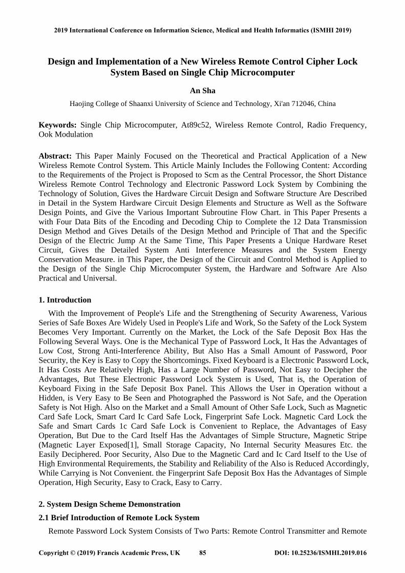
Control System. the User Can Enter the Password from the Remote Transmitter on the 10 Meter Range, and Then Send out the Transmitter. Remote Control Receiving System Receives User Input Password by a Microprocessor to Decipher and Compared with the Original Set a Password for Comparison, If by Comparing is Actuated by an Electromagnet to Drive the Door Lock, If the Comparison Fails Does Not Produce Any Operation. and Remote Control Password Lock System with General Electronic Password Lock System Common Features, the System Can Be Set by the User's Own Password, Password Consists of 1 to 8 out of 10 Digits, a Maximum of 10 to the 8th a Combination, High Safety and to the Illegal Unlocking Operation for Self-Locking of Punishment, Also Issued a Bee Buzzing Warning[2]. in Addition Each Set Remote Control Password Lock System is Also Equipped with a Group of Backup Password, to Meet Some Special Place, Such as the Management of the Hotel. Users in the Use of the System, Only after the Opening of the Remote Control System in Order to Use a Mechanical Key to Open the Safe, You Can Make the Insurance Box with a Double Insurance Function, So That the Safe Deposit Box. At the Same Time, the Remote Control is Universal, Easy to Produce, Even If the Remote Controller is Stolen or Lost, Because of the Secrecy of the Password, Other People Can Not Open the System. in Order to Overcome the Shortages of the Current Market of Electronic Password Lock to Meet the User's Different Needs, Ningbo Yongfa Corporation Proposed with the Combination of the Wireless Remote Control Method and Cipher Technology, in Order to Ensure the Original Password Lock System Performance Based on the Research and Development of New Remote Password Lock System to Overcome the Shortcomings of the Fixed Keyboard Password Lock, Enables Users to Any Position in a Certain Range of the Safe to Open, So as to Ensure the Security of Password. This New Remote Control Lock System to Fill the Gaps in the Domestic, to Provide Users with More Secure and Reliable Products, But Also Will Enhance the Company's Market Competitiveness[3]. Ppm Modulation Waveform is Shown in Figure 1:
Fig.1 Ppm Modulated Waveform.
2.2 Infrared Coding and Transmitting Module Scheme one: dedicated chip solutions. Special infrared coding chip many kinds, such as Mitsubishi Corporation of Japan M50426AP,
PT2262, BL9148, ZD6631 etc., such chips generally set carrier oscillation, encoding, transmitting in one, has a strong anti-interference ability, simple peripheral circuits, the use is very convenient, and the price is very low. Most of the remote control devices use such a dedicated chip. However, ASIC has fatal weakness: special chip application flexibility is poor, its internal code has been fixed cannot modify internal data, does not apply to often need to change data transfer; special chip are almost oriented instruction code remote control mode, transmission efficiency is low; most of the special chip internal code and the technical data have been submitted to, security breaches.
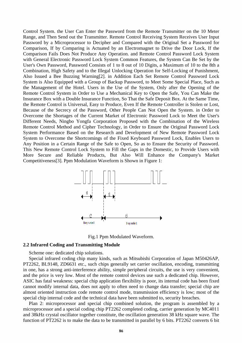
Plan 2: microprocessor and special chip combined solution, the program is assembled by a microprocessor and a special coding chip PT2262 completed coding, carrier generation by MC4011 and 38kHz crystal oscillator together constitute, the oscillation generation 38 kHz square wave. The function of PT2262 is to make the data to be transmitted in parallel by 6 bits. PT2262 converts 6 bit
86
parallel data into serial data, reduces the programming burden, and makes the transmission speed faster. A6/D0 A11/D5 ~ PT2262 a total of 6 multiplexing port for the data port, the PT2262 automatically send the microprocessor 6 data into serial data from the Dout port. The scheme can make the number of password, the encoding and decoding algorithm and the synchronization signal[4], and greatly improve the data security. The disadvantage is that the use of the PT2262, the increase in the cost of hardware and circuit complexity. The program uses the I/O port of the microprocessor to directly generate 38KHz modulated wave, which drives the infrared emitting diode to transmit the infrared data. 38KHz square wave generated by the CPU timer or by the software programming. Infrared coding work is completed by the software. Therefore, infrared coding scheme can arbitrary design, external only with very simple hardware circuit, greatly reduce the complexity of the circuit, is conducive to reducing the cost, decreases the volume of remote. Due to the use of software coding scheme, occupy the CPU time CPU processing speed is influenced by certain, however, for the function of remote control as compared to the single system, processing tasks is relatively small, the fundamental implications of CPU processing efficiency, only increase the burden of programming software. By comparison, the program two can not only meet the requirements of the topic, the circuit is very simple, the cost of hardware is very low, only to increase the burden on the programming software, making the infrared coding is very flexible, so the use of the program[5]. Infrared coding and transmission module program design is shown in figure 2:
Fig.2 Infrared Coding and Transmitting Module Plan Design.
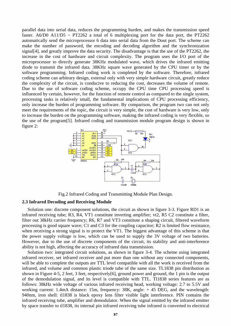
2.3 Infrared Decoding and Receiving Module Solution one: discrete component solutions, the circuit as shown in figure 3-3. Figure RD1 is an
infrared receiving tube; R3, R4, VT1 constitute inverting amplifier; vt2, R5 C2 constitute a filter, filter out 38kHz carrier frequency; R6, R7 and VT3 constitute a shaping circuit, filtered waveform processing is good square wave; C1 and C3 for the coupling capacitor; R2 is limited flow resistance, when receiving a strong signal is to protect the VT1. The biggest advantage of this scheme is that the power supply voltage is low, which can be used to supply the 3V voltage of two batteries. However, due to the use of discrete components of the circuit, its stability and anti-interference ability is not high, affecting the accuracy of infrared data transmission.
Solution two: integrated circuit solutions, as shown in figure 3-4. The scheme using integrated infrared receiver, set infrared receiver and put more than one without any connected components, will be able to complete the outputs are TTL level compatible with all the work is received from the infrared, and volume and common plastic triode tube of the same size. TL1838 pin distribution as shown in Figure 4-5, 2 feet, 3 feet, respectively[6], ground power and ground, the 1 pin is the output of the demodulation signal, and its level is compatible with TTL. Tl1838 series features are as follows: 38kHz wide voltage of various infrared receiving head, working voltage: 2.7 to 5.5V and working current: 1.4mA distance: 15m, frequency: 38K, angle: + 45 DEG, and the wavelength: 940nm, iron shell: tl1838 is black epoxy lens filter visible light interference. PIN contains the infrared receiving tube, amplifier and demodulator. When the signal emitted by the infrared emitter by space transfer to tl1838, its internal pin infrared receiving tube infrared is converted to electrical
87
signal, the signal by the frequency selective amplification, demodulation by 1 foot outputs are TTL level compatible with the electrical signal, the signal can be directly sent to the microprocessor for processing. The output waveform of TL1838 is shown in figure 3-6. When receiving the infrared signal in the frequency band and tl1838 receiver can output low level, otherwise the infrared signal demodulation of the data at a high level, thus the intermittent “into the original continuous square wave signal. Tl1838 advantages of good stability, anti-interference ability is very strong, peripheral circuit is very simple, without the high cost for infrared remote control and IR data transmission, is an alternative to other infrared receiving amplifier ideal components. And its operating voltage is 2.7 ~ 5.5V, the effective transmission distance of 15M, is a cost-effective infrared integrated receiver. By comparison, the program two can not only meet the requirements of the topic, the circuit is very simple, the cost of hardware is very low, through the software programming, making the infrared coding is very flexible, so the use of the program. The low voltage infrared receiving circuit is shown in figure 3:
Fig.3 Schematic Diagram of Infrared Receiving Circuit with Low Voltage.
2.4 Data Storage Module Design Infrared key (from the machine) encryption program and the host generated password stored in
the AT24C02, when you need to change or read the password, only the AT24C02 in the data changes or read. The circuit should pay attention to is SCL, SDA must add a pullup resistor value for 10K. AT24C01 is the United States I2C production of ATMEL serial E2PROM. It can be used for electric erase, programmable read-only memory, self timed write cycle, including automatic erase time is not more than 10ms, the typical time is 5ms. The working voltage of 2.7V chip to 6V, erasable 1 million times, data can be stored for 100 years, with 8 pin DIP and SOIC packages. AT24C01 allows a number of bytes of 1 bytes to 1 pages to write in a write cycle, the size of a page depends on the size of the chip. WP: write protection. Connect the pin to E2PROM, VCC to achieve write protection (read only). When the pin is grounded or floating, the device can read and write operation SCL: serial clock pin serial input and output data, which is used for inputting the clock. SDA: serial data / address input pin bidirectional serial data / address foot, used to enter the output data. The foot is the output of the emitter (drain), and it needs to be connected with the pull up resistor. A0A1A2: select or select input. For chip addressing. AT24C01 no internal connection. The main device begins to transmit after the start command is sent, the main device transmits the corresponding address from the device, and the 8 bit from the device address is fixed to 1010 bits 4. The next 3 bits (see Figure 4-11) are used to define the address of the memory, which has no meaning to the AT24C02 bit. The last one to read and write control bit. “1” means read operation, “0” means to write operation. After each data transfer is successful, the receiver sends a response signal. When the ninth clock signal is generated[7], the receiver will be SDA drop down to low, the notification has been received 8 data. Data storage circuit diagram is shown in figure 4:
88
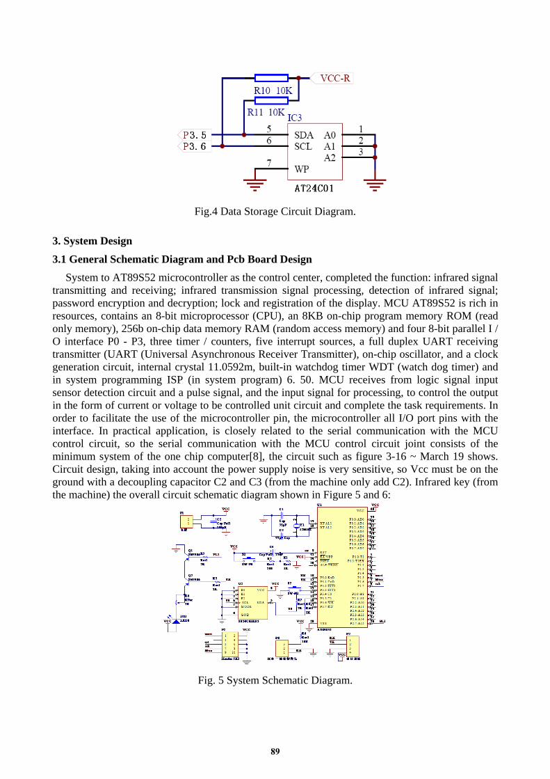
Fig.4 Data Storage Circuit Diagram.
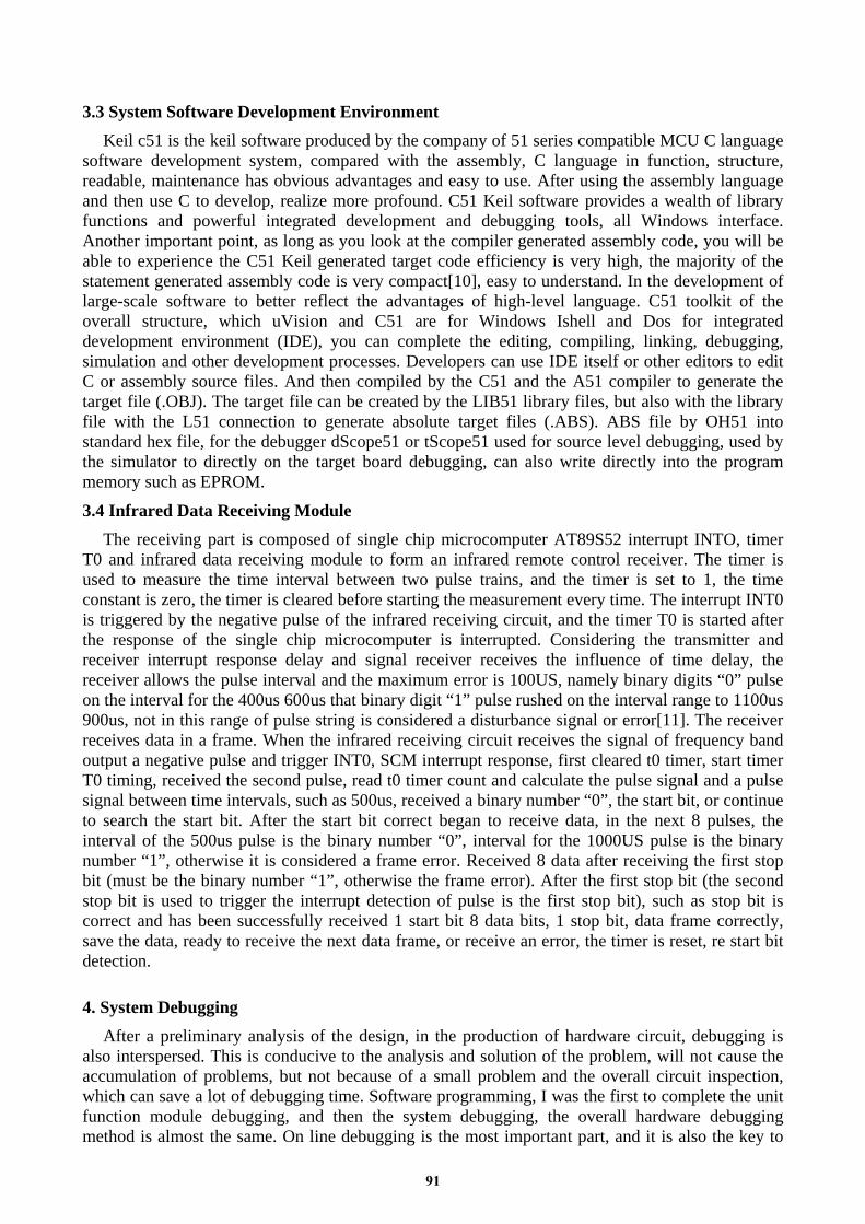
3. System Design 3.1 General Schematic Diagram and Pcb Board Design
System to AT89S52 microcontroller as the control center, completed the function: infrared signal transmitting and receiving; infrared transmission signal processing, detection of infrared signal; password encryption and decryption; lock and registration of the display. MCU AT89S52 is rich in resources, contains an 8-bit microprocessor (CPU), an 8KB on-chip program memory ROM (read only memory), 256b on-chip data memory RAM (random access memory) and four 8-bit parallel I / O interface P0 - P3, three timer / counters, five interrupt sources, a full duplex UART receiving transmitter (UART (Universal Asynchronous Receiver Transmitter), on-chip oscillator, and a clock generation circuit, internal crystal 11.0592m, built-in watchdog timer WDT (watch dog timer) and in system programming ISP (in system program) 6. 50. MCU receives from logic signal input sensor detection circuit and a pulse signal, and the input signal for processing, to control the output in the form of current or voltage to be controlled unit circuit and complete the task requirements. In order to facilitate the use of the microcontroller pin, the microcontroller all I/O port pins with the interface. In practical application, is closely related to the serial communication with the MCU control circuit, so the serial communication with the MCU control circuit joint consists of the minimum system of the one chip computer[8], the circuit such as figure 3-16 ~ March 19 shows. Circuit design, taking into account the power supply noise is very sensitive, so Vcc must be on the ground with a decoupling capacitor C2 and C3 (from the machine only add C2). Infrared key (from the machine) the overall circuit schematic diagram shown in Figure 5 and 6:
Fig. 5 System Schematic Diagram.
89
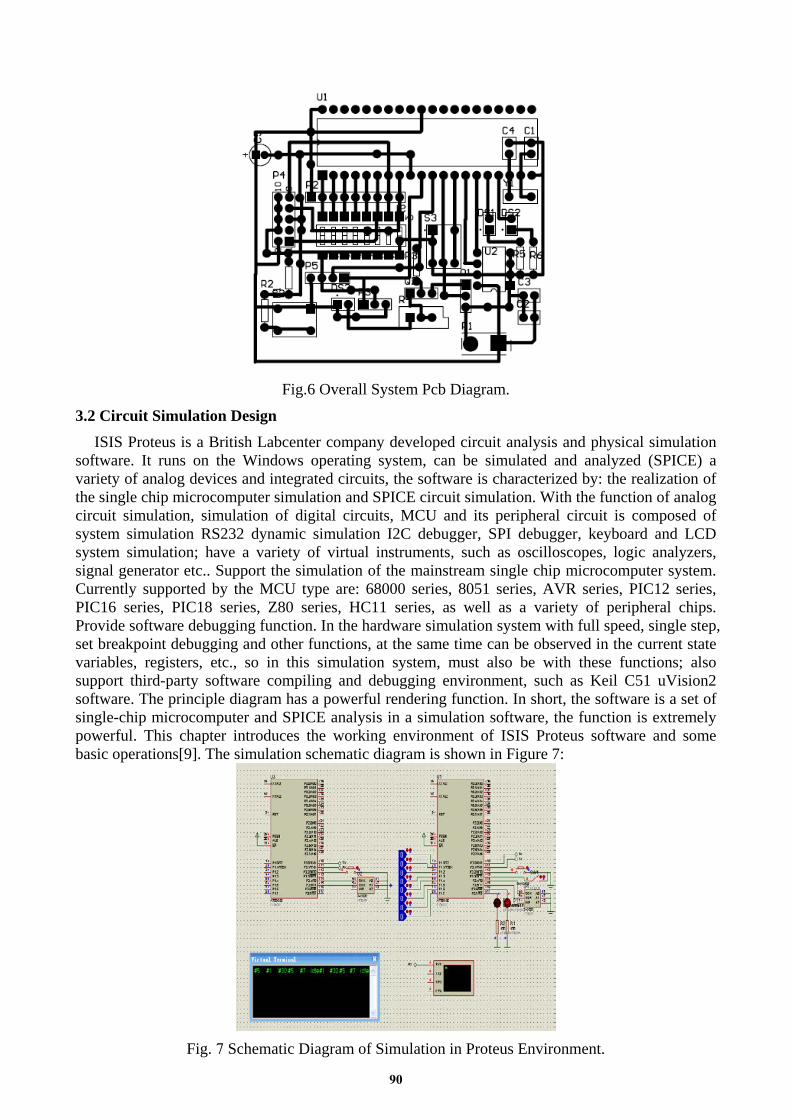
Fig.6 Overall System Pcb Diagram.
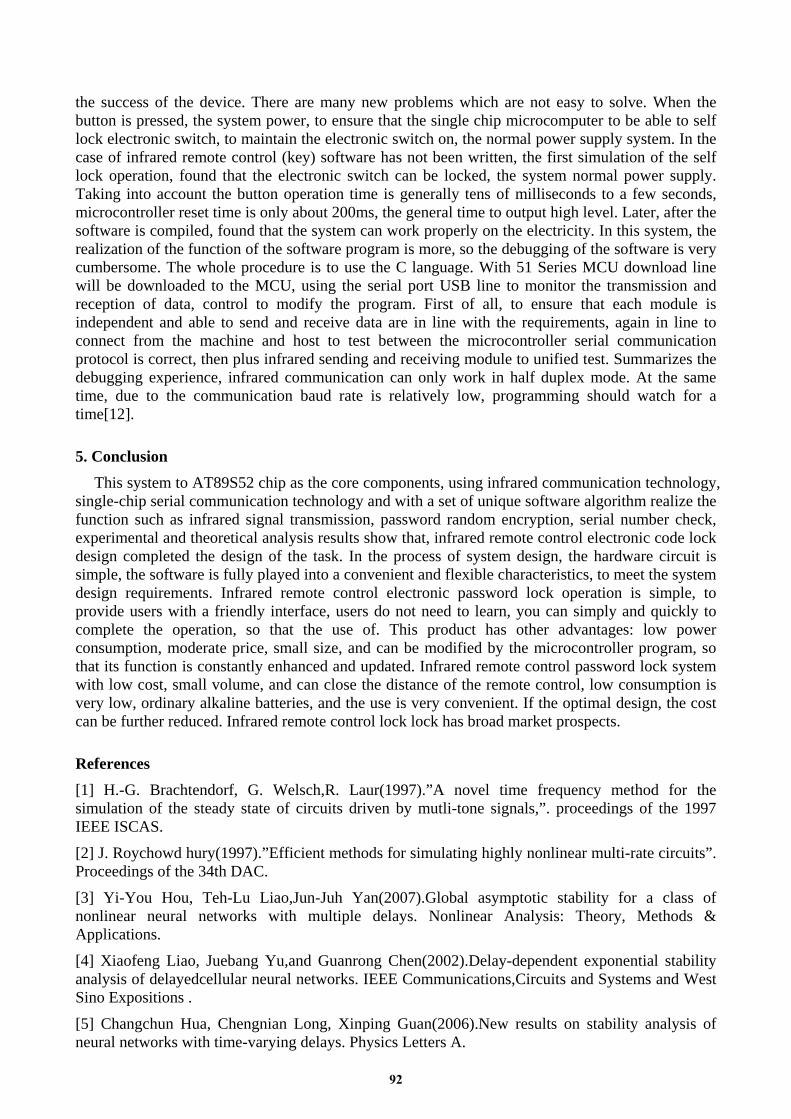
3.2 Circuit Simulation Design ISIS Proteus is a British Labcenter company developed circuit analysis and physical simulation
software. It runs on the Windows operating system, can be simulated and analyzed (SPICE) a variety of analog devices and integrated circuits, the software is characterized by: the realization of the single chip microcomputer simulation and SPICE circuit simulation. With the function of analog circuit simulation, simulation of digital circuits, MCU and its peripheral circuit is composed of system simulation RS232 dynamic simulation I2C debugger, SPI debugger, keyboard and LCD system simulation; have a variety of virtual instruments, such as oscilloscopes, logic analyzers, signal generator etc.. Support the simulation of the mainstream single chip microcomputer system. Currently supported by the MCU type are: 68000 series, 8051 series, AVR series, PIC12 series, PIC16 series, PIC18 series, Z80 series, HC11 series, as well as a variety of peripheral chips. Provide software debugging function. In the hardware simulation system with full speed, single step, set breakpoint debugging and other functions, at the same time can be observed in the current state variables, registers, etc., so in this simulation system, must also be with these functions; also support third-party software compiling and debugging environment, such as Keil C51 uVision2 software. The principle diagram has a powerful rendering function. In short, the software is a set of single-chip microcomputer and SPICE analysis in a simulation software, the function is extremely powerful. This chapter introduces the working environment of ISIS Proteus software and some basic operations[9]. The simulation schematic diagram is shown in Figure 7:
Fig. 7 Schematic Diagram of Simulation in Proteus Environment.
90
3.3 System Software Development Environment Keil c51 is the keil software produced by the company of 51 series compatible MCU C language
software development system, compared with the assembly, C language in function, structure, readable, maintenance has obvious advantages and easy to use. After using the assembly language and then use C to develop, realize more profound. C51 Keil software provides a wealth of library functions and powerful integrated development and debugging tools, all Windows interface. Another important point, as long as you look at the compiler generated assembly code, you will be able to experience the C51 Keil generated target code efficiency is very high, the majority of the statement generated assembly code is very compact[10], easy to understand. In the development of large-scale software to better reflect the advantages of high-level language. C51 toolkit of the overall structure, which uVision and C51 are for Windows Ishell and Dos for integrated development environment (IDE), you can complete the editing, compiling, linking, debugging, simulation and other development processes. Developers can use IDE itself or other editors to edit C or assembly source files. And then compiled by the C51 and the A51 compiler to generate the target file (.OBJ). The target file can be created by the LIB51 library files, but also with the library file with the L51 connection to generate absolute target files (.ABS). ABS file by OH51 into standard hex file, for the debugger dScope51 or tScope51 used for source level debugging, used by the simulator to directly on the target board debugging, can also write directly into the program memory such as EPROM.
3.4 Infrared Data Receiving Module The receiving part is composed of single chip microcomputer AT89S52 interrupt INTO, timer
T0 and infrared data receiving module to form an infrared remote control receiver. The timer is used to measure the time interval between two pulse trains, and the timer is set to 1, the time constant is zero, the timer is cleared before starting the measurement every time. The interrupt INT0 is triggered by the negative pulse of the infrared receiving circuit, and the timer T0 is started after the response of the single chip microcomputer is interrupted. Considering the transmitter and receiver interrupt response delay and signal receiver receives the influence of time delay, the receiver allows the pulse interval and the maximum error is 100US, namely binary digits “0” pulse on the interval for the 400us 600us that binary digit “1” pulse rushed on the interval range to 1100us 900us, not in this range of pulse string is considered a disturbance signal or error[11]. The receiver receives data in a frame. When the infrared receiving circuit receives the signal of frequency band output a negative pulse and trigger INT0, SCM interrupt response, first cleared t0 timer, start timer T0 timing, received the second pulse, read t0 timer count and calculate the pulse signal and a pulse signal between time intervals, such as 500us, received a binary number “0”, the start bit, or continue to search the start bit. After the start bit correct began to receive data, in the next 8 pulses, the interval of the 500us pulse is the binary number “0”, interval for the 1000US pulse is the binary number “1”, otherwise it is considered a frame error. Received 8 data after receiving the first stop bit (must be the binary number “1”, otherwise the frame error). After the first stop bit (the second stop bit is used to trigger the interrupt detection of pulse is the first stop bit), such as stop bit is correct and has been successfully received 1 start bit 8 data bits, 1 stop bit, data frame correctly, save the data, ready to receive the next data frame, or receive an error, the timer is reset, re start bit detection.
4. System DebuggingAfter a preliminary analysis of the design, in the production of hardware circuit, debugging is
also interspersed. This is conducive to the analysis and solution of the problem, will not cause the accumulation of problems, but not because of a small problem and the overall circuit inspection, which can save a lot of debugging time. Software programming, I was the first to complete the unit function module debugging, and then the system debugging, the overall hardware debugging method is almost the same. On line debugging is the most important part, and it is also the key to
91
the success of the device. There are many new problems which are not easy to solve. When the button is pressed, the system power, to ensure that the single chip microcomputer to be able to self lock electronic switch, to maintain the electronic switch on, the normal power supply system. In the case of infrared remote control (key) software has not been written, the first simulation of the self lock operation, found that the electronic switch can be locked, the system normal power supply. Taking into account the button operation time is generally tens of milliseconds to a few seconds, microcontroller reset time is only about 200ms, the general time to output high level. Later, after the software is compiled, found that the system can work properly on the electricity. In this system, the realization of the function of the software program is more, so the debugging of the software is very cumbersome. The whole procedure is to use the C language. With 51 Series MCU download line will be downloaded to the MCU, using the serial port USB line to monitor the transmission and reception of data, control to modify the program. First of all, to ensure that each module is independent and able to send and receive data are in line with the requirements, again in line to connect from the machine and host to test between the microcontroller serial communication protocol is correct, then plus infrared sending and receiving module to unified test. Summarizes the debugging experience, infrared communication can only work in half duplex mode. At the same time, due to the communication baud rate is relatively low, programming should watch for a time[12].
5. ConclusionThis system to AT89S52 chip as the core components, using infrared communication technology,
single-chip serial communication technology and with a set of unique software algorithm realize the function such as infrared signal transmission, password random encryption, serial number check, experimental and theoretical analysis results show that, infrared remote control electronic code lock design completed the design of the task. In the process of system design, the hardware circuit is simple, the software is fully played into a convenient and flexible characteristics, to meet the system design requirements. Infrared remote control electronic password lock operation is simple, to provide users with a friendly interface, users do not need to learn, you can simply and quickly to complete the operation, so that the use of. This product has other advantages: low power consumption, moderate price, small size, and can be modified by the microcontroller program, so that its function is constantly enhanced and updated. Infrared remote control password lock system with low cost, small volume, and can close the distance of the remote control, low consumption is very low, ordinary alkaline batteries, and the use is very convenient. If the optimal design, the cost can be further reduced. Infrared remote control lock lock has broad market prospects.
References [1] H.-G. Brachtendorf, G. Welsch,R. Laur(1997).”A novel time frequency method for thesimulation of the steady state of circuits driven by mutli-tone signals,”. proceedings of the 1997IEEE ISCAS.[2] J. Roychowd hury(1997).”Efficient methods for simulating highly nonlinear multi-rate circuits”.Proceedings of the 34th DAC.[3] Yi-You Hou, Teh-Lu Liao,Jun-Juh Yan(2007).Global asymptotic stability for a class ofnonlinear neural networks with multiple delays. Nonlinear Analysis: Theory, Methods &Applications.[4] Xiaofeng Liao, Juebang Yu,and Guanrong Chen(2002).Delay-dependent exponential stabilityanalysis of delayedcellular neural networks. IEEE Communications,Circuits and Systems and WestSino Expositions .[5] Changchun Hua, Chengnian Long, Xinping Guan(2006).New results on stability analysis ofneural networks with time-varying delays. Physics Letters A.
92
[6] Cao Jinde, Wang Jun(2003).Global asymptotic stability of a general class of recurrent neuralnetworks with time-varying delays. IEEE Transactions on Circuits and Systems I:FundamentalTheory and Applications .[7] He Y, Wang Q, Xie L, et al(2007).Further improvement of free-weighting matrices techniquefor systems with time-varying delay. IEEE Transactions on Automatic Control.[8] Gu K(2000).An integral inequality in the stability problem of time-delay systems. Proceedingsof the 39th IEEE Conference in Decision and Control.[9] Ungerboeck G(1987).Trellis-coded modulation with redundant signal sets. IEEECommunications Magazine.[10] T. Roska, T. Boros,P. Thiran,and L(1999). O Chua. Detecting simple motion using cellularneural networks:. Proc IEEE Int. Workshop on Cellular Neural Networks and Their Applications.[11] Sabri Arik(2003).Global asymptotic stability of a larger class of delayed neural networks.IEEE Circuits and Systems, 2003.ISCAS’03.Proceedings of the2003International Symposium.[12] Vimal Singh(2004).A Generalized LMI-Based approach to the global asymptotic stability ofcellular neural networks. IEEE Transaction on Neural Network.
93