COMSOL Implementation for Two-Phase Immiscible Flows in ...
15
COMSOL Implementation for Two-Phase Immiscible Flows in Layered Reservoir 1/15 Xuan Zhang Center for Energy Recourses Engineering Technical University of Denmark COMSOL 2010, France, Nov. 17, 2010 Presented at the COMSOL Conference 2010 Paris
Transcript of COMSOL Implementation for Two-Phase Immiscible Flows in ...
COMSOL Implementation for Two-Phase
Immiscible Flows in Layered Reservoir
1/15
Xuan Zhang
Center for Energy Recourses Engineering
Technical University of Denmark
COMSOL 2010, France, Nov. 17, 2010
Presented at the COMSOL Conference 2010 Paris
Outline
� Introduction
� Implementation
� Results
Conclusion
2/15
� Conclusion
COMSOL 2010, France, Nov. 17, 2010
Introduction
, , , ,h k s sφ
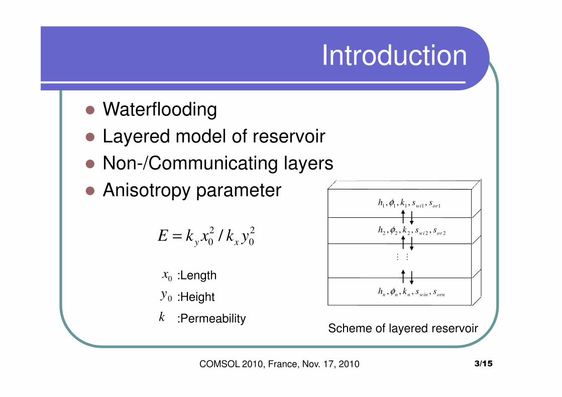
� Waterflooding
� Layered model of reservoir
� Non-/Communicating layers
� Anisotropy parameter
3/15
1 1 1 1 1, , , ,
wi orh k s sφ
2 2 2 2 2, , , ,wi orh k s sφ
…
…
, , , ,n n n win orn
h k s sφ
� Anisotropy parameter
2 2
0 0/y xE k x k y=
:Length
:Height
:Permeability
0x
0y
kScheme of layered reservoir
COMSOL 2010, France, Nov. 17, 2010
Introduction
U U∂ ∂
( ) ( )0X YU F s U F ss
T X Yφ
∂ ∂∂+ + =
∂ ∂ ∂
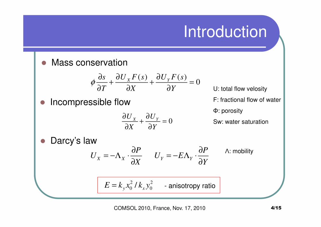
� Mass conservation
� Incompressible flow
U: total flow velosity
F: fractional flow of water
Φ: porosity
4/15
0X YU U
X Y
∂ ∂+ =
∂ ∂
� Darcy’s law
X X Y Y
P PU U E
X Y
∂ ∂= −Λ ⋅ = − Λ ⋅
∂ ∂
Φ: porosity
Sw: water saturation
Λ: mobility
2 2
0 0/y xE k x k y= - anisotropy ratio
COMSOL 2010, France, Nov. 17, 2010
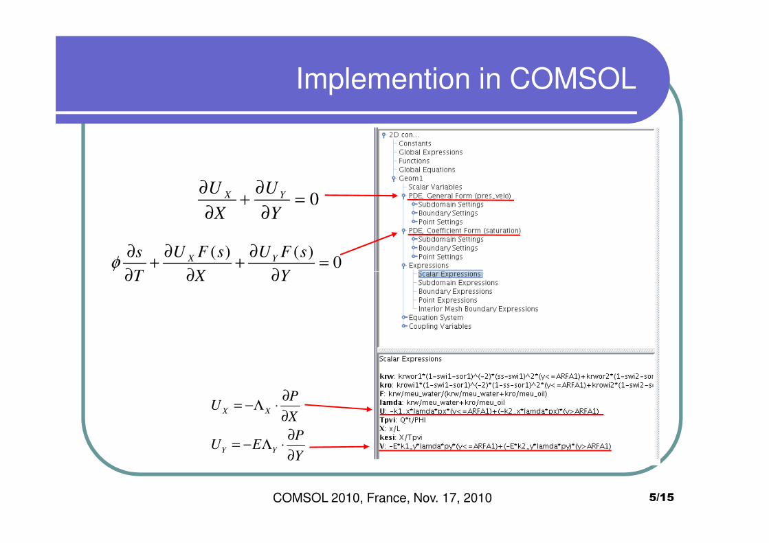
Implemention in COMSOL
( ) ( )0X Y
U F s U F ss
T X Yφ
∂ ∂∂+ + =
∂ ∂ ∂
0X YU U
X Y
∂ ∂+ =
∂ ∂
5/15COMSOL 2010, France, Nov. 17, 2010
T X Y∂ ∂ ∂
X X
Y Y
PU
X
PU E
Y
∂= −Λ ⋅
∂
∂= − Λ ⋅
∂
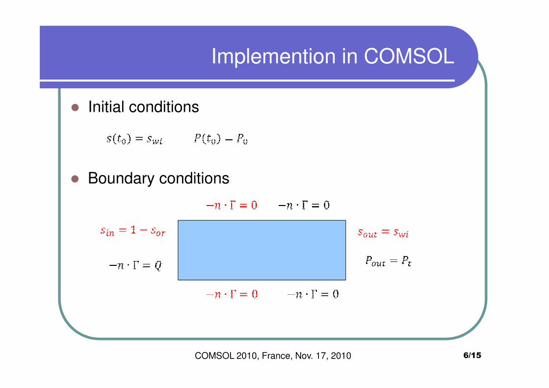
Implemention in COMSOL
� Initial conditions
� Boundary conditions
COMSOL 2010, France, Nov. 17, 2010 6/15
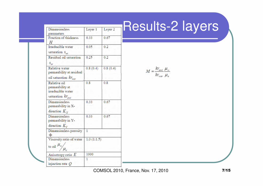
Results-2 layers
7/15COMSOL 2010, France, Nov. 17, 2010
Results- 2 layers
8/15
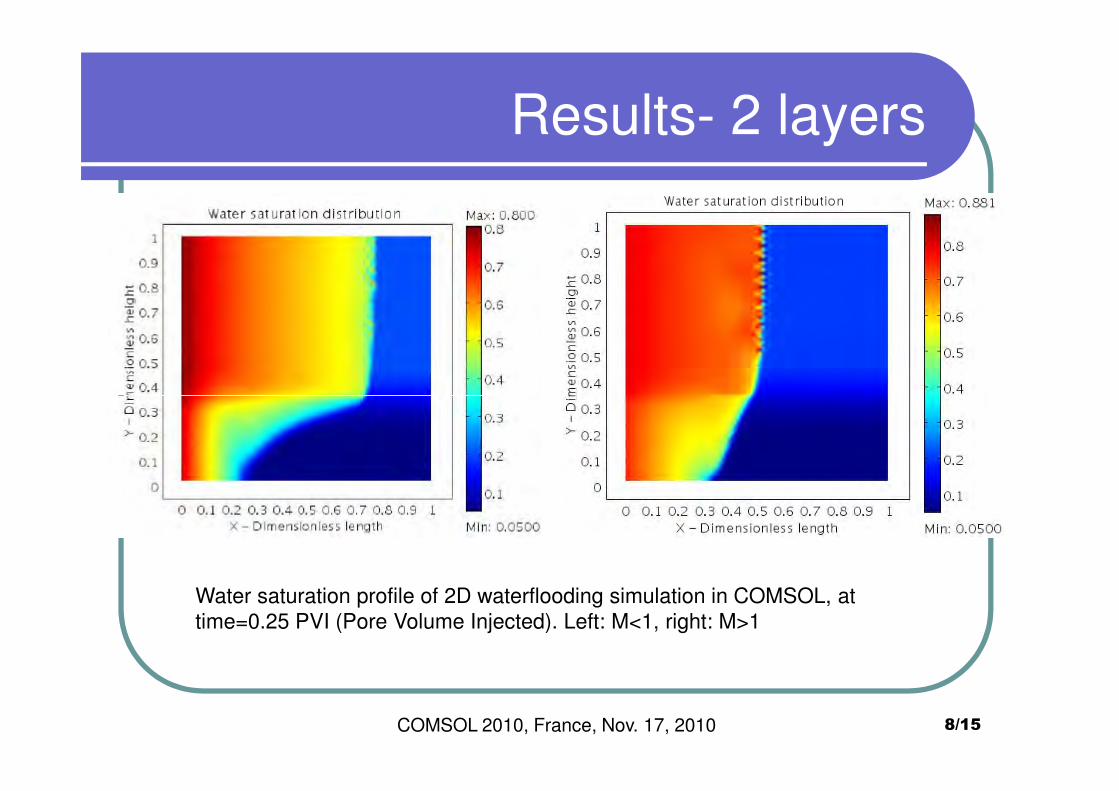
Water saturation profile of 2D waterflooding simulation in COMSOL, at
time=0.25 PVI (Pore Volume Injected). Left: M<1, right: M>1
COMSOL 2010, France, Nov. 17, 2010
Comparision with analytical solution
9/15
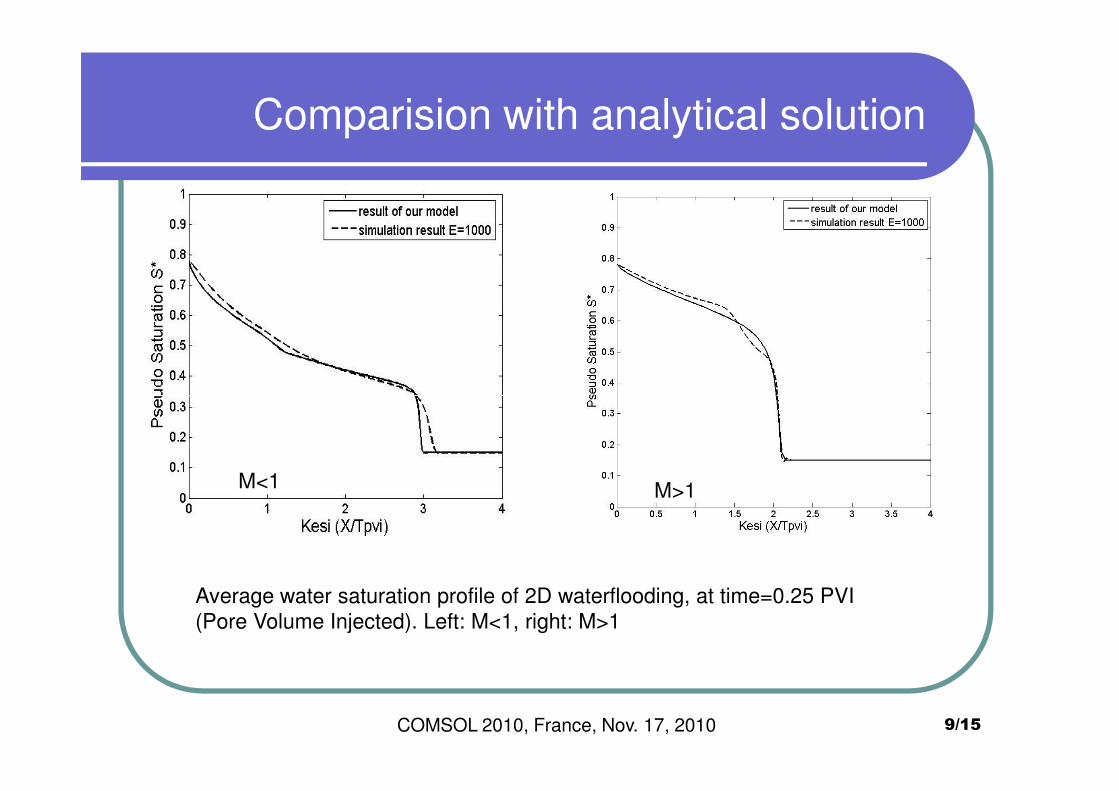
M<1 M>1
COMSOL 2010, France, Nov. 17, 2010
Average water saturation profile of 2D waterflooding, at time=0.25 PVI
(Pore Volume Injected). Left: M<1, right: M>1
Analytical derivation
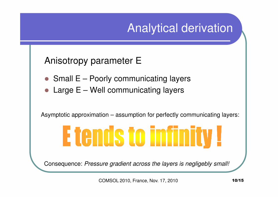
Anisotropy parameter E
� Small E – Poorly communicating layers
� Large E – Well communicating layers
10/15
Asymptotic approximation – assumption for perfectly communicating layers:
Consequence: Pressure gradient across the layers is negligebly small!
COMSOL 2010, France, Nov. 17, 2010
Analytical derivation
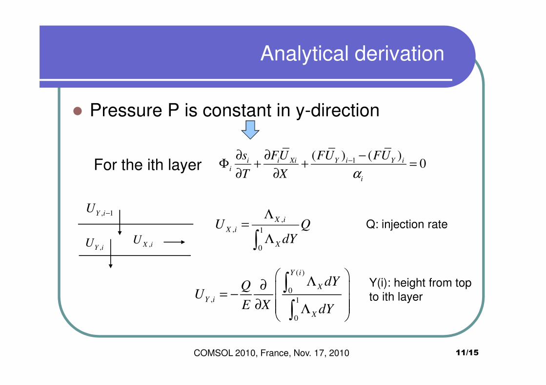
� Pressure P is constant in y-direction
For the ith layer 1( ) ( )0i i Xi Y i Y i
i
i
s FU FU FU
T X α−∂ ∂ −
Φ + + =∂ ∂
11/15
,
, 1
0
X i
X i
X
U QdY
Λ=
Λ∫Q: injection rate
( )
0, 1
0
Y i
X
Y i
X
dYQU
E X dY
Λ∂ = − ∂ Λ
∫
∫
Y(i): height from top
to ith layer
,X iU
,Y iU
, 1Y iU −
COMSOL 2010, France, Nov. 17, 2010
Results: log-normal distributed permeability
12/15
M>1M<1
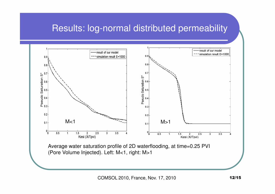
Average water saturation profile of 2D waterflooding, at time=0.25 PVI
(Pore Volume Injected). Left: M<1, right: M>1
COMSOL 2010, France, Nov. 17, 2010

Results:Levels of communication between layers
13/15COMSOL 2010, France, Nov. 17, 2010
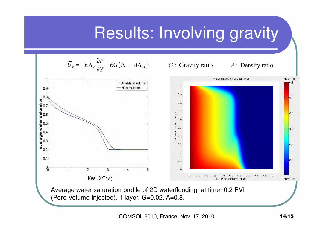
Results: Involving gravity
( )Y Y Y oY
PU E EG A
Y
∂= − Λ − Λ − Λ
∂: Gravity ratioG : Density ratioA
14/15COMSOL 2010, France, Nov. 17, 2010
Average water saturation profile of 2D waterflooding, at time=0.2 PVI
(Pore Volume Injected). 1 layer. G=0.02, A=0.8.
Conclusions
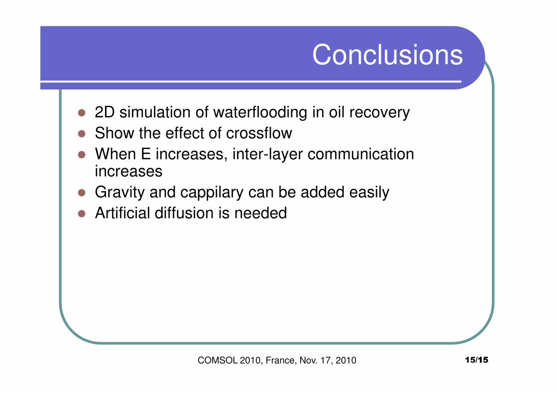
� 2D simulation of waterflooding in oil recovery
� Show the effect of crossflow
� When E increases, inter-layer communication increases
� Gravity and cappilary can be added easily
1515/15
� Gravity and cappilary can be added easily
� Artificial diffusion is needed
COMSOL 2010, France, Nov. 17, 2010


![EFFECT OF AROMATIC OIL ON PHASE DYNAMICS OF S … 2016 paper... · immiscible IR (polyisoprene) / NR (natural rubber) blends [4] are used due to the improved wet-skid resistance.](https://static.fdocument.org/doc/165x107/5aaa30d17f8b9a72188de79b/effect-of-aromatic-oil-on-phase-dynamics-of-s-2016-paperimmiscible-ir-polyisoprene.jpg)