Chhaapptteerr VV - Shodhgangashodhganga.inflibnet.ac.in/bitstream/10603/51383/9/09_chapter5.pdf ·...
49
Chapter V E I S CHARACTERIZATION Objective of this chapter To study the impedance characteristics of DSSCs 5.1. Introduction The steady-state J–V characteristic of DSSCs provide the performance parameters of the cell, such as the short-circuit current (Jsc), open-circuit potential (Voc), fill factor (FF) and photocurrent efficiency (η). Nevertheless, more detailed properties cannot be extracted from steady-state measurements, and so dynamic techniques should be considered. These techniques allow the interpretation of the charge-transfer kinetics, mainly characterized by diffusion coefficients and lifetime of the different charge carriers. One of the most powerful characterization techniques of DSSCs involving transient probing is electrochemical impedance spectroscopy (EIS). EIS is a dynamic technique that has many advantages, not only because it is user-friendly but also for the reason that of its sensitivity and ability to separate different complex processes occurring in DSSCs (Wang, et al., 2005; Bisquert, 2002; Fabregat-Santiago, et al., 2002). Despite being a relatively easy method to apply to the study of electrochemical systems, the results may sometimes be difficult to interpret. The use of equivalent electrical analogs to fit the EIS experimental data is a useful tool in this respect, as it helps to identify and interpret the characteristic parameters of the system, such as, for instance, the internal resistances of DSSCs. 5.2. Electrochemical impedance spectroscopy EIS is a powerful technique for the characterization of electrochemical systems. It is one of the most useful experimental techniques as it permits a
Transcript of Chhaapptteerr VV - Shodhgangashodhganga.inflibnet.ac.in/bitstream/10603/51383/9/09_chapter5.pdf ·...
147 Chapter V
CChhaapptteerr VV
E I S CHARACTERIZATION
Objective of this chapter
To study the impedance characteristics of DSSCs
5.1. Introduction
The steady-state J–V characteristic of DSSCs provide the performance
parameters of the cell, such as the short-circuit current (Jsc), open-circuit potential
(Voc), fill factor (FF) and photocurrent efficiency (η). Nevertheless, more detailed
properties cannot be extracted from steady-state measurements, and so dynamic
techniques should be considered. These techniques allow the interpretation of the
charge-transfer kinetics, mainly characterized by diffusion coefficients and lifetime
of the different charge carriers. One of the most powerful characterization techniques
of DSSCs involving transient probing is electrochemical impedance spectroscopy
(EIS).
EIS is a dynamic technique that has many advantages, not only because it is
user-friendly but also for the reason that of its sensitivity and ability to separate
different complex processes occurring in DSSCs (Wang, et al., 2005; Bisquert, 2002;
Fabregat-Santiago, et al., 2002). Despite being a relatively easy method to apply to
the study of electrochemical systems, the results may sometimes be difficult to
interpret. The use of equivalent electrical analogs to fit the EIS experimental data is a
useful tool in this respect, as it helps to identify and interpret the characteristic
parameters of the system, such as, for instance, the internal resistances of DSSCs.
5.2. Electrochemical impedance spectroscopy
EIS is a powerful technique for the characterization of electrochemical
systems. It is one of the most useful experimental techniques as it permits a
148 Chapter V
simultaneous characterization of the different processes taking place in the cell
(Bisquert and Mora-Ser, 2010; Walker, et al., 2006). In EIS measurements the
potential applied to the solar cell is perturbed by a small amplitude sinusoidal
modulation and the resulting sinusoidal current response is measured as a function of
the modulation frequency (Oekermann, et al., 2005).
The meaning of electrical impedance can be understood starting from the
concept of resistance. The electrical resistance is the ability of a circuit element to
resist the flow of electrical current. The well known Ohm's law defines resistance (R)
in terms of the ratio between voltage (V) and current (I). This relationship is limited to
only one circuit element, an ideal resistor. But usually the systems under study contain
circuit elements that exhibit a much more complex behaviour. The simple concept of
resistance needs to be replaced by a more general parameter: the impedance, which
includes not only the relative amplitudes of the voltage and the current, but also the
relative phases. Like resistance, impedance is a measure of the ability of a circuit to
resist the flow of electrical current (Villanueva-Cab, et al., 2010).
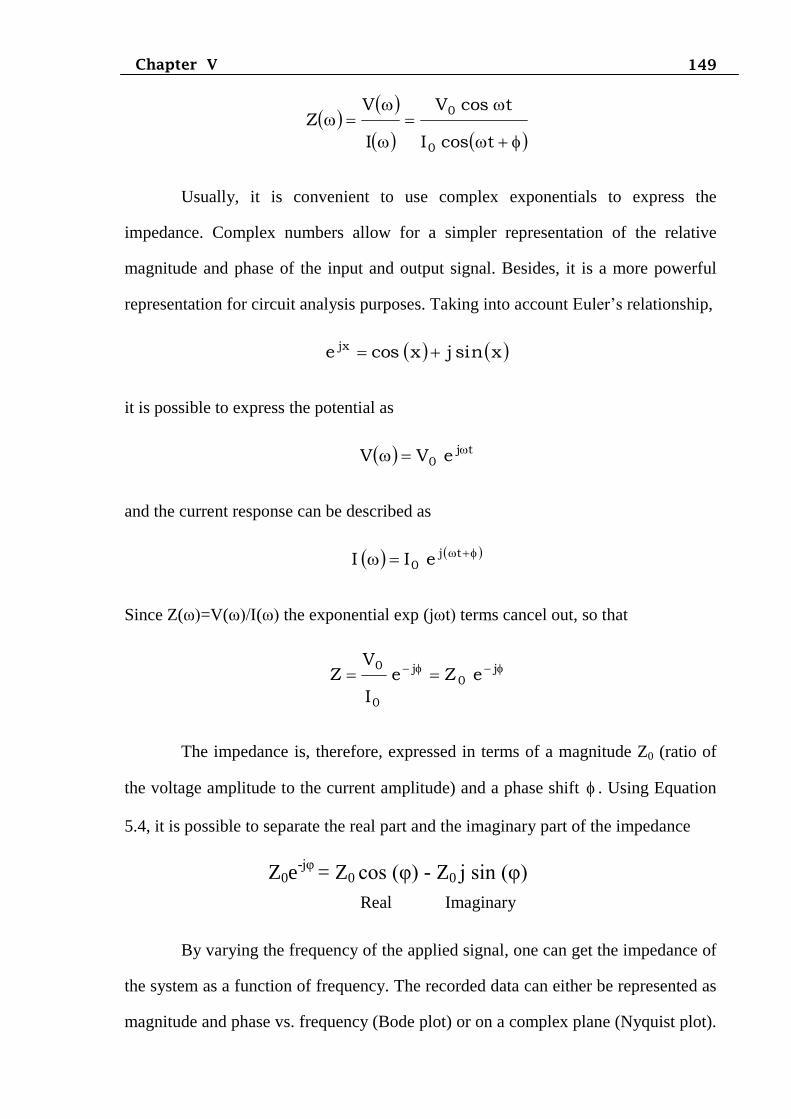
The excitation signal can be written as
V(ω) = V0 cos ωt
where V(ω) is the ac potential applied to the system, V0 is the amplitude signal and ω
is the angular frequency (ω = 2πf rad s-1
). The current response will be shifted with
respect to the applied potential
I(ω) = I0 cos (ωt+ )
where I(ω) is the ac electrical current response signal, I0 the amplitude and the
phase shift. The phase factor contains the current lag with respect to the voltage. An
expression analogous to Ohm’s law allows for calculating the impedance of the
system as
149 Chapter V
tcosI
tcosV
I
VZ
0
0
Usually, it is convenient to use complex exponentials to express the
impedance. Complex numbers allow for a simpler representation of the relative
magnitude and phase of the input and output signal. Besides, it is a more powerful
representation for circuit analysis purposes. Taking into account Euler’s relationship,
xsinjxcose jx
it is possible to express the potential as
tj0 eVV
and the current response can be described as
tj0 eII
Since Z(ω)=V(ω)/I(ω) the exponential exp (jωt) terms cancel out, so that
j0
j
0
0eZe
I
VZ
The impedance is, therefore, expressed in terms of a magnitude Z0 (ratio of
the voltage amplitude to the current amplitude) and a phase shift . Using Equation
5.4, it is possible to separate the real part and the imaginary part of the impedance
Z0e-jφ
= Z0 cos (φ) - Z0 j sin (φ)
Real Imaginary
By varying the frequency of the applied signal, one can get the impedance of
the system as a function of frequency. The recorded data can either be represented as
magnitude and phase vs. frequency (Bode plot) or on a complex plane (Nyquist plot).
150 Chapter V
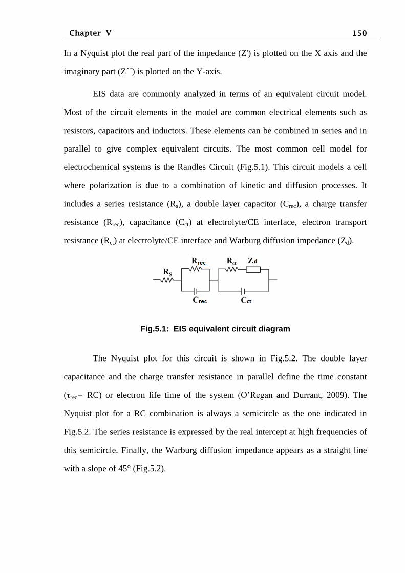
In a Nyquist plot the real part of the impedance (Z') is plotted on the X axis and the
imaginary part (Z´´) is plotted on the Y-axis.
EIS data are commonly analyzed in terms of an equivalent circuit model.
Most of the circuit elements in the model are common electrical elements such as
resistors, capacitors and inductors. These elements can be combined in series and in
parallel to give complex equivalent circuits. The most common cell model for
electrochemical systems is the Randles Circuit (Fig.5.1). This circuit models a cell
where polarization is due to a combination of kinetic and diffusion processes. It
includes a series resistance (Rs), a double layer capacitor (Crec), a charge transfer
resistance (Rrec), capacitance (Cct) at electrolyte/CE interface, electron transport
resistance (Rct) at electrolyte/CE interface and Warburg diffusion impedance (Zd).
Fig.5.1: EIS equivalent circuit diagram
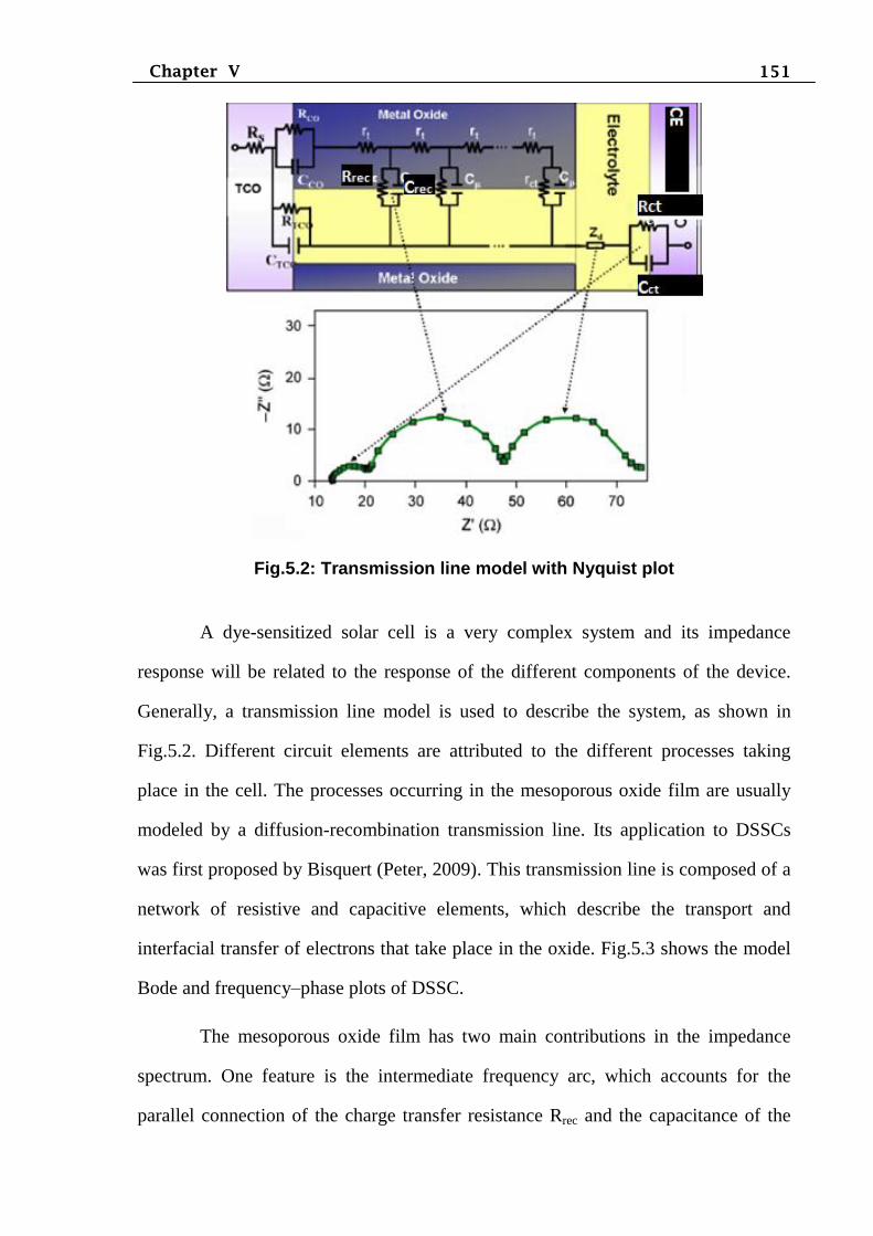
The Nyquist plot for this circuit is shown in Fig.5.2. The double layer
capacitance and the charge transfer resistance in parallel define the time constant
(τrec= RC) or electron life time of the system (O’Regan and Durrant, 2009). The
Nyquist plot for a RC combination is always a semicircle as the one indicated in
Fig.5.2. The series resistance is expressed by the real intercept at high frequencies of
this semicircle. Finally, the Warburg diffusion impedance appears as a straight line
with a slope of 45° (Fig.5.2).
151 Chapter V
Fig.5.2: Transmission line model with Nyquist plot
A dye-sensitized solar cell is a very complex system and its impedance
response will be related to the response of the different components of the device.
Generally, a transmission line model is used to describe the system, as shown in
Fig.5.2. Different circuit elements are attributed to the different processes taking
place in the cell. The processes occurring in the mesoporous oxide film are usually
modeled by a diffusion-recombination transmission line. Its application to DSSCs
was first proposed by Bisquert (Peter, 2009). This transmission line is composed of a
network of resistive and capacitive elements, which describe the transport and
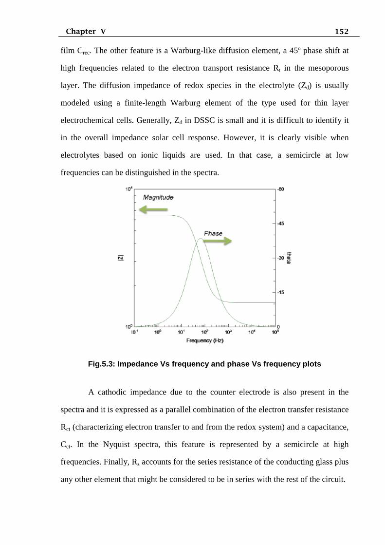
interfacial transfer of electrons that take place in the oxide. Fig.5.3 shows the model
Bode and frequency–phase plots of DSSC.
The mesoporous oxide film has two main contributions in the impedance
spectrum. One feature is the intermediate frequency arc, which accounts for the
parallel connection of the charge transfer resistance Rrec and the capacitance of the
152 Chapter V
film Crec. The other feature is a Warburg-like diffusion element, a 45º phase shift at
high frequencies related to the electron transport resistance Rt in the mesoporous
layer. The diffusion impedance of redox species in the electrolyte (Zd) is usually
modeled using a finite-length Warburg element of the type used for thin layer
electrochemical cells. Generally, Zd in DSSC is small and it is difficult to identify it
in the overall impedance solar cell response. However, it is clearly visible when
electrolytes based on ionic liquids are used. In that case, a semicircle at low
frequencies can be distinguished in the spectra.
Fig.5.3: Impedance Vs frequency and phase Vs frequency plots
A cathodic impedance due to the counter electrode is also present in the
spectra and it is expressed as a parallel combination of the electron transfer resistance
Rct (characterizing electron transfer to and from the redox system) and a capacitance,
Cct. In the Nyquist spectra, this feature is represented by a semicircle at high
frequencies. Finally, Rs accounts for the series resistance of the conducting glass plus
any other element that might be considered to be in series with the rest of the circuit.
153 Chapter V
The other useful electrochemical parameters of DSSCs are keff (rate of
recombination of the electrons in the photoanode film), τrec (effective electron life
time), Ln (electron diffusion length), Deff (effective diffusion coefficient),
µ (electron mobility), σ (electron conductivity), ηcc (electron collection efficiency)
and concentration of electrons in the TiO2/dye/electrolyte interface. These
parameters are calculated from the following expressions (Adachi, et al., 2006).
The lifetime of electrons in DSSC is a particularly important quantity. The
measured lifetime is a strong function of the Fermi level or open-circuit photo
voltage, Voc. The lifetime is a kinetic quantity that contains information not only on
the rate constants of charge transfer but also on the distribution of electronic states
and electronic transitions that intervene in the operation of the DSSC.
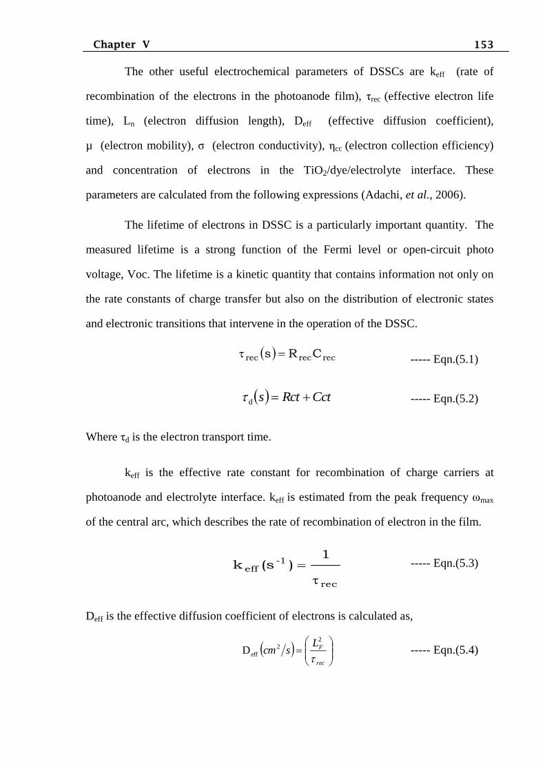
recrecrec CRs
----- Eqn.(5.1)
CctRcts d ----- Eqn.(5.2)
Where τd is the electron transport time.
keff is the effective rate constant for recombination of charge carriers at
photoanode and electrolyte interface. keff is estimated from the peak frequency ωmax
of the central arc, which describes the rate of recombination of electron in the film.
rec
1-eff
1)s(k
----- Eqn.(5.3)
Deff is the effective diffusion coefficient of electrons is calculated as,
rec
FLscm
22
effD ----- Eqn.(5.4)
154 Chapter V
The diffusion length Ln is the distance that an electron travels through the film before
it is recombined to the acceptor
21
effrecn DmL ----- Eqn.(5.5)
Conductivity of the photoanode film
eff
B
effD
TK
eDsVcm 9.382 ----- Eqn.(5.6)
Electron mobility
rec
F
RP1S
LcmmS
----- Eqn.(5.7)
Electron collection efficiency
rec
d
cc 1 ----- Eqn.(5.8)
Concentration of charge carriers describes the charge transport resistance and its
recombination rate along the entire thickness of working electrode and is calculated
as
effFrec kLRscmConc. ----- Eqn.(5.9)
where, LF - the film thickness of the photoanode (15 µm); S-active area of the
DSSCs; P-porosity of the photoanode film (0.6); (Rct x Crec); e – Charge of an
electron; KB - Boltzmann constant; T – Room temperature
The electrochemical impedance spectra were fitted using the Zsimpwin
software by means of equivalent circuit shown in Fig.5.1.
155 Chapter V
5.3. Experimental
Electron impedance spectra of DSSCs were recorded with Gamry-300
impedance analyzer. The applied bias voltage and ac amplitude were set at open-
circuit voltage of the DSSCs at 10 mV between the ITO/CE at the ITO/TiO2/dye
working electrode, respectively, and the frequency range explored was 1 mHz to
105 Hz. The impedance spectra were analyzed by an equivalent circuit model
interpreting the characteristics of the DSSCs through Zsimpwin software
(www.gamry.com). Fig.5.4 shows the Gamry impedance analyzer.
Fig.5.4: Gamry impedance analyzer
(Impedance analyzer (EIS) – EIS 300 specifications)
Overview
The EIS 300 Electrochemical Impedance Spectroscopy allows us to measure
impedances spanning 15 orders of magnitude over a frequency range of 10 µHz to 1
MHz. Data analysis in the Echem Analyst is easy. Spectra can be fit to standard cell
models or custom models created with graphical Model Editor. Gamry EIS 300 data
files ZSimpWin and Equivalent Circuit.
Data Acquisition Features
Continuous AC amplitude and DC offset correction for the most accurate
potential and current measurement.

156 Chapter V
Lissajous (I vs. E) real-time display at each frequency.
Bode or Nyquist real-time display of spectrum as it develops.
Realtime monitoring of signal-to-noise ratio for deciding when a
measurement is done for the best data in the shortest time.
Data Analysis Features
Impedance or Admittance plots.
Graphic Model Editor for equivalent circuit models with the ability to define
custom components.
Choice of Levenberg-Marquardt or Simplex algorithms in fitting the data to
equivalent circuits.
Kramers-Kronig Transform to evaluate the quality of the EIS data.
A unique Auto-Fit routine takes the guesswork out of estimating initial
values for your model elements.
System Requirements
Gamry PCI4/Series G, Reference, or Interface Family Instrument
Microsoft® Windows™ XP SP3/Vista/7/8 (32-bit or 64-bit)
157 Chapter V
5.4 Results and discussion
Electron transport properties of DSSCs were investigated using
electrochemical impedance spectroscopy (EIS). In general, the Nyquist plot exhibited
three semicircles, which are attributed to the redox reaction at the counter electrode
in the high-frequency region, the electron transfer at the TiO2/dye/electrolyte
interface in the middle-frequency region and carrier transport by ions within the
electrolytes in the low-frequency region. The model equivalent circuit diagram
(shown in Fig. 5.1) consisted of a series of resistance (Rs, starting point of the first
semicircle in Nyquist plot), electron transport resistance at the counter
electrode/electrolyte (Rct, first semicircle in Nyquist plot), charge transfer resistance
at the photoanode/electrolyte (Rrec, second semicircle in Nyquist plot), the constant
phase elements of capacitance Crec (Rrec), Cct (Rct) and Warburg diffusion impedance
Zd. The charge transfer kinetics has been explained on the basis of the diffusion–
recombination model proposed by Bisquert, 2002 and has been frequently employed
to analyze similar structures (Bisquert, 2002; Tan and Wu, 2006 ; Wu et al., 2008).
The internal impedances Rs, Rrec, Rct, Zd were determined from EIS analysis and
listed in Tables 5.1, 5.3 and 5.5. The other useful electrochemical parameters of
DSSCs, keff (rate of recombination of the electrons in the film), τeff (effective electron
life time), Ln (electron diffusion length), Deff (effective diffusion coefficient), µ
(electron mobility), σ (electron conductivity), ηcc (electron collection efficiency) and
concentration of electrons in the TiO2/dye/electrolyte interface were calculated using
Eqns. (5.1)-(5.9) and presented in Tables 5.1, 5.3 and 5.5.
5.5 EIS characterization of DSSCs made with core-shell photoanode
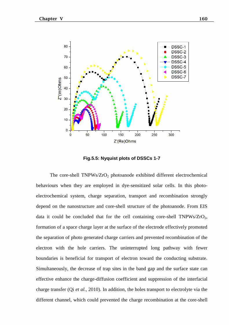
Fig. 5.5 shows the Nyquist plots of DSSCs made with different types
photoanodes and electrolytes. From the Nyquist plots it could be seen that first and
third semicircles are weak when compared the second semicircle. From the Fig. 5.5,
158 Chapter V
comparison of the middle semicircles of Nyquist plot of the DSSCs made with
different electrolytes indicated the decrease of the diameter in the order
DSSC-1>DSSC-3>DSSC-2>DSSC-4, suggested that DSSC-4 contributed to the
lowest charge transfer resistance at the TiO2/dye/electrolyte interface. When
comparing the Nyquist plots of DSSC-4 and DSSC-5, the Rrec value is increased in
DSSC-5 due to uncoated ZrO2 photoanode. Similarly when comparing the Nyquist
plots of DSSC-4 and DSSC-6, the Rrec value is increased in DSSC-6 due to uncoated
blocking layer HfO2. The DSSC-7 showed the highest value of Rrec. In this study,
higher charge collection efficiency is achieved in DSSC-4 based on TNPWs/ZrO2
core-shell with HfO2 blocking layer structure photoanode through quasi-solid state
electrolyte as compared to the other cells.
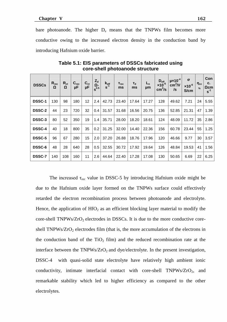
From the Table 5.1 it could be observed that the DSSC-4 made with novel
photoanode strucuture illustrated higher values of Crec, τrec, Ln, Deff, µ, σ and ηcc as
comparing other DSSCs. In addition, keff and concentration of electrons in the
TiO2/dye/electrolyte interface are lower values as compared to the other DSSCs.
Control of interfacial electron injection and recombination at the
photoanode/dye/electrolyte interface is pivotal for the best performance of DSSCs.
Modification at the metal oxide/dye interface has received increased attention among
researchers to improve the injection efficiency and suppress the recombination as the
interfacial energetic can be controlled by this strategy. Introducing shell layer on the
surface of photoanode materials exerts larger dipole moment that changes the
interface energetic in an energetically more favourable way for electron transfer
(Watson and Meyer, 2004). Recombination rate was diminished because the
insertion of ZrO2 could shield electron back flow through TNPWs to the electrolyte.
In the present investigation, the surface modification of photoanode with very thin
layer as well as larger band gap shell material improved the photocurrent.
159 Chapter V
Hence, core-shell material provided faster electron injection, and suppressed
recombination at photoanode/dye/electrolyte interface. In our examination on the
performance of core–shell structure-based DSSCs hints that the essential
improvement in electron injection efficiency and thereby overall performance can be
obtained by proper designing of the second metal oxide with suitable band gap,
optimal thickness of shell layer and IEP.
In addition, one-dimensional (1D) nanostructure, the grain boundaries effect
could be restricted (Fujihara et al., 2007, Baxter and Aydil, 2006). Moreover, the
loading of dye can be much higher in 1D nano structured material than the
nanoparticles, for instance, the TNPWs has allowed for larger adsorption of dye.
These results were indicated that the combining TNWs with TNPs having relatively
high thermal stability and low aggregation property. The enhanced charge collection
efficiency of the TNPWs/ZrO2 core-shell DSSCs is achieved by optimizing device
architectures, which enhanced light absorption and facilitated electron transport by
determining and designing appropriate dimensions of TNPWs/ZrO2, by optimizing
the cation concentration in the electrolyte solution for promoting electron injection
yield from sensitizing D149 dye molecules to core-shell TNPWs/ZrO2 electrodes, or
by synthesizing thermally stable TNPWs with a stable high surface area. In the core-
shell TNPWs/ZrO2 photoanode, the lower Rrec suggested that each TNWs made more
difficult for an electron to jump outside the nanostructure than to stay within the
structure during diffusion; this explained the high charge collectin collection
efficiency and thus high short-circuit photocurrent.
160 Chapter V
Fig.5.5: Nyquist plots of DSSCs 1-7
The core-shell TNPWs/ZrO2 photoanode exhibited different electrochemical
behaviours when they are employed in dye-sensitized solar cells. In this photo-
electrochemical system, charge separation, transport and recombination strongly
depend on the nanostructure and core-shell structure of the photoanode. From EIS
data it could be concluded that for the cell containing core-shell TNPWs/ZrO2,
formation of a space charge layer at the surface of the electrode effectively promoted
the separation of photo generated charge carriers and prevented recombination of the
electron with the hole carriers. The uninterrupted long pathway with fewer
boundaries is beneficial for transport of electron toward the conducting substrate.
Simultaneously, the decrease of trap sites in the band gap and the surface state can
effective enhance the charge-diffusion coefficient and suppression of the interfacial
charge transfer (Qi et al., 2010). In addition, the holes transport to electrolyte via the
different channel, which could prevented the charge recombination at the core-shell
161 Chapter V
TNPWs/ZrO2/redox electrolyte interfaces and led to the electrons diffusion and
transport become easy. Therefore, the DSSCs based on the core-shell TNPWs/ZrO2
film with QSSE has the lower values for Rrec, Rct and the longer electron lifetime,
consequently led to an enhanced charge collection efficiency of the cell. Electron
transport in core-shell TNPWs/ZrO2 photoanode is tortuous and often confront with
dead end (Hagfeldt et al., 2010), which enormously increased the electron transport
route.
As revealed from Table 5.1, the presence of core-shell TNPWs/ZrO2 layer
increased the electron lifetime and made the electron transfer more easily. In other
words, the charge transfer resistance in core-shell TNPWs/ZrO2 interfaces and
electron recombination are decreased, led to a positive influence on the improvement
of solar cell performance. Hence with EIS investigation, it is observed that the
enhanced electron transport properties, reduced charge recombination and increased
electron life-time which are imperative for higher solar cell performance in DSSC-4.
Therefore, DSSCs fabricated with core-shell TNPWs/ZrO2, which provided direct
and enhanced charge transport while minimizing charge recombination resulted in
enhanced the charge collection efficiency. Use of core-shell nanostructure to lower
the charge recombination is based on a hypothesis that a coating layer might build up
an energy barrier at the semiconductor/electrolyte interface and, thus, retarded the
reaction between the photogenerated electrons and the redox species in electrolyte.
In core-shell nanostructure, an energy barrier is established at the
semiconductor/electrolyte interface, it required that the conduction band potential of
the shell material is more negative than that of the core material. As such, the back
electron transport is retarded and the interfacial recombination could be reduced
(Kanmani and Ramachadran, 2012). The De and τrec values of the DSSC-5 with
Hafnium oxide layer are shown to be higher than those of DSSC-7 built with TNPWs
162 Chapter V
bare photoanode. The higher De means that the TNPWs film becomes more
conductive owing to the increased electron density in the conduction band by
introducing Hafnium oxide barrier.
Table 5.1: EIS parameters of DSSCs fabricated using core-shell photoanode structure
DSSCs Rrec
Ω
Rct
Ω Crec
µF Cct
µF
Zd
Ω-s
0.5
keff s
-1
τrec
ms τd
ms Ln
µm
Deff
×10-6
cm2/s
µ×10-4
cm2/V
/s
σ
×10-6
S/cm
ηcc
%
Conc.
Ωcms
-1
DSSC-1 130 98 180 12 2.4 42.73 23.40 17.64 17.27 128 49.62 7.21 24 5.55
DSSC-2 44 23 720 32 0.4 31.57 31.68 16.56 20.75 136 52.85 21.31 47 1.39
DSSC-3 80 52 350 19 1.4 35.71 28.00 18.20 18.61 124 48.09 11.72 35 2.86
DSSC-4 40 18 800 35 0.2 31.25 32.00 14.40 22.36 156 60.78 23.44 55 1.25
DSSC-5 96 67 280 15 2.0 37.20 26.88 18.76 17.96 120 46.66 9.77 30 3.57
DSSC-6 48 28 640 28 0.5 32.55 30.72 17.92 19.64 126 48.84 19.53 41 1.56
DSSC-7 140 108 160 11 2.6 44.64 22.40 17.28 17.08 130 50.65 6.69 22 6.25
The increased τrec value in DSSC-5 by introducing Hafnium oxide might be
due to the Hafnium oxide layer formed on the TNPWs surface could effectively
retarded the electron recombination process between photoanode and electrolyte.
Hence, the application of HfO2 as an efficient blocking layer material to modify the
core-shell TNPWs/ZrO2 electrodes in DSSCs. It is due to the more conductive core-
shell TNPWs/ZrO2 electrodes film (that is, the more accumulation of the electrons in
the conduction band of the TiO2 film) and the reduced recombination rate at the
interface between the TNPWs/ZrO2 and dye/electrolyte. In the present investigation,
DSSC-4 with quasi-solid state electrolyte have relatively high ambient ionic
conductivity, intimate interfacial contact with core-shell TNPWs/ZrO2, and
remarkable stability which led to higher efficiency as compared to the other
electrolytes.
163 Chapter V
The cell performance confirms that suitable coating of ZrO2 shell layer with
TNPWs core film can suppress the charge recombination process effectively and
improve the overall conversion efficiency. Fig. 5.5, which suggests that the
improvement in ηcc and τrec result from a suppression of the charge recombination by
ZrO2 shell coating. The role and the mechanism of the wide-band semiconductor as
shell coating on TiO2 have been discussed in many researches (Chen et al., 2001 and
Kruger et al., 2000). The present study shows that the thin ZrO2 shell coating can
suppress the charge recombination. Since, ZrO2 has a conduction band more negative
than that of TiO2, ZrO2 shell coating on TNPWs surface can form an energy barrier
on the surface of photoanode, which can suppress the injected electrons from
recombination with oxidized dye or I3-, thus reduces the charge recombination
process and increases the conversion efficiency (Chen et al., 2001; Kruger et al.,
2000; Burnside et al., 1999; Lenzmann et al., 2001; Vilan et al., 2000). Generally, it
can be found that reasonable thickness of the shell layer is beneficial to suppress the
recombination process and achieve relative high conversion efficiency.
Fig.5.5 shows EIS of the cells of DSSC-4 and 5 with and without ZrO2 shell
coating. The result also confirms that DSSC with ZrO2 shell coating has less electron
recombination at the photoanode/dye/electrolyte interface and longer electron
lifetime compared with the uncoated DSSC-5. Thus the application of ZrO2 shell
coating on TNPWs composite photoanode can promote the interfacial electron
transfer and suppress the electron recombination effectively.
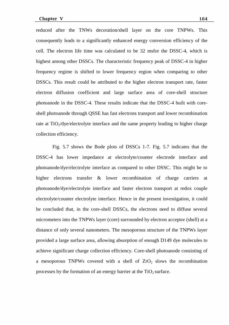
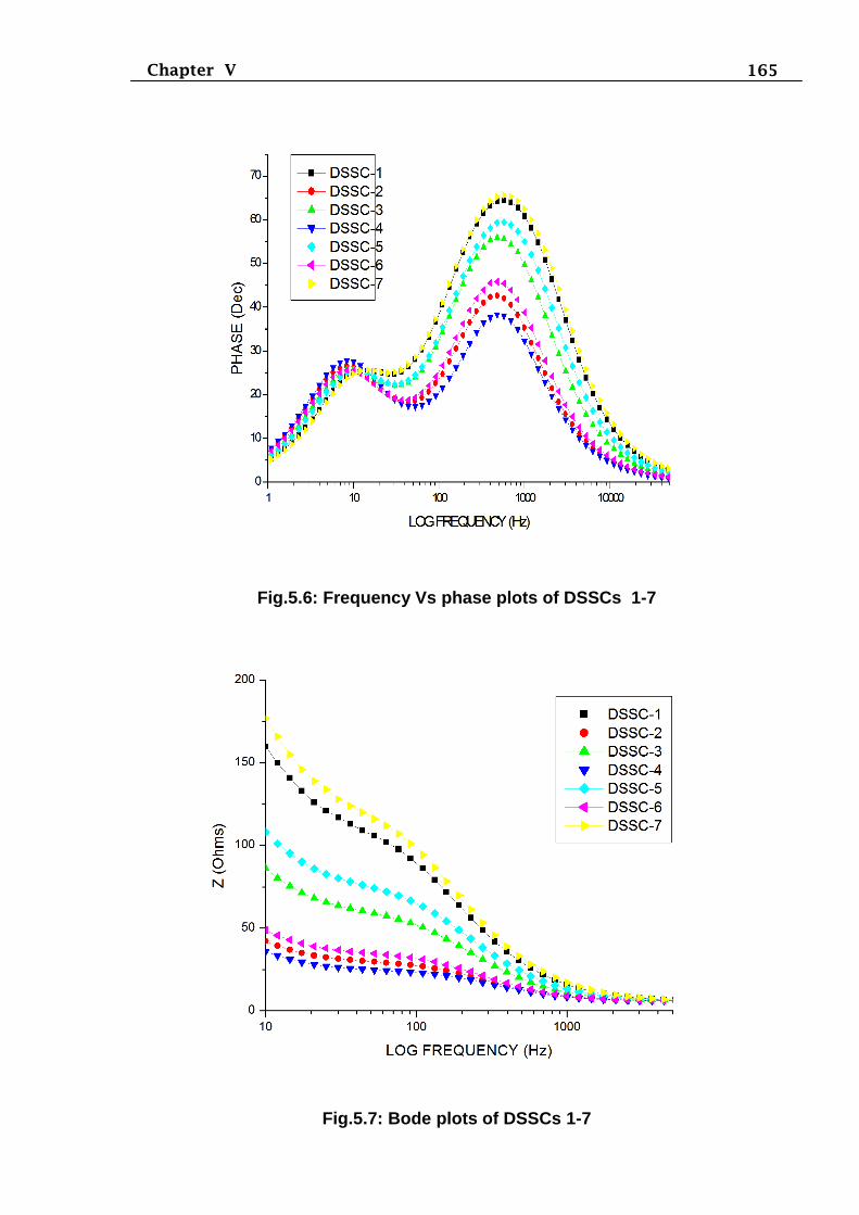
From the frequency - phase plots in the lower frequency regime, it can be seen
that the characteristic frequency peak of DSSC-4 shifted to lower frequency as
compared to other DSSCs. The peak shifted to a lower frequency indicates an
increased lifetime of the DSSC-4. The longer lifetime implied a lower recombination
rate and enhanced charge collection efficiency. Therefore the interfacial charge
recombination of TNPs between the photo-injected electron and electrolyte materials
164 Chapter V
reduced after the TNWs decoration/shell layer on the core TNPWs. This
consequently leads to a significantly enhanced energy conversion efficiency of the
cell. The electron life time was calculated to be 32 msfor the DSSC-4, which is
highest among other DSSCs. The characteristic frequency peak of DSSC-4 in higher
frequency regime is shifted to lower frequency region when comparing to other
DSSCs. This result could be attributed to the higher electron transport rate, faster
electron diffusion coefficient and large surface area of core-shell structure
photoanode in the DSSC-4. These results indicate that the DSSC-4 built with core-
shell photoanode through QSSE has fast electrons transport and lower recombination
rate at TiO2/dye/electrolyte interface and the same property leading to higher charge
collection efficiency.
Fig. 5.7 shows the Bode plots of DSSCs 1-7. Fig. 5.7 indicates that the
DSSC-4 has lower impedance at electrolyte/counter electrode interface and
photoanode/dye/electrolyte interface as compared to other DSSC. This might be to
higher electrons transfer & lower recombination of charge carriers at
photoanode/dye/electrolyte interface and faster electron transport at redox couple
electrolyte/counter electrolyte interface. Hence in the present investigation, it could
be concluded that, in the core-shell DSSCs, the electrons need to diffuse several
micrometers into the TNPWs layer (core) surrounded by electron acceptor (shell) at a
distance of only several nanometers. The mesoporous structure of the TNPWs layer
provided a large surface area, allowing absorption of enough D149 dye molecules to
achieve significant charge collection efficiency. Core-shell photoanode consisting of
a mesoporous TNPWs covered with a shell of ZrO2 slows the recombination
processes by the formation of an energy barrier at the TiO2 surface.
165 Chapter V
Fig.5.6: Frequency Vs phase plots of DSSCs 1-7
Fig.5.7: Bode plots of DSSCs 1-7
166 Chapter V
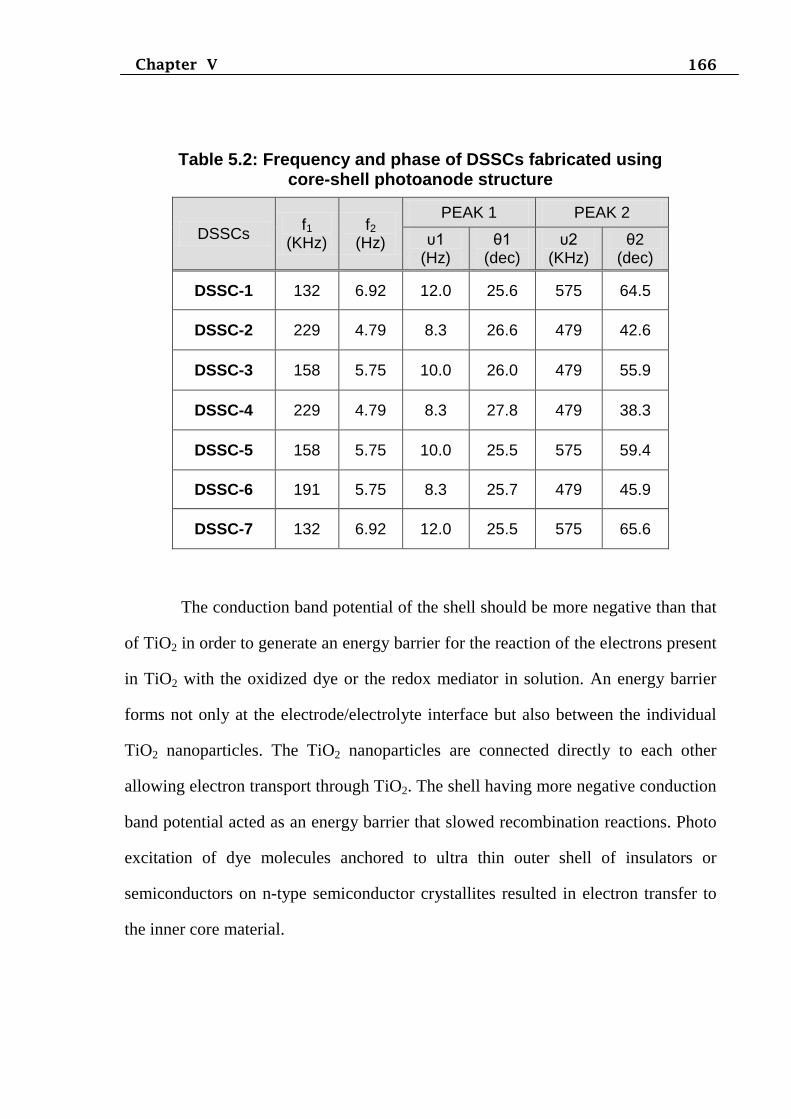
Table 5.2: Frequency and phase of DSSCs fabricated using core-shell photoanode structure
DSSCs f1
(KHz)
f2 (Hz)
PEAK 1 PEAK 2
υ1 (Hz)
θ1 (dec)
υ2 (KHz)
θ2 (dec)
DSSC-1 132 6.92 12.0 25.6 575 64.5
DSSC-2 229 4.79 8.3 26.6 479 42.6
DSSC-3 158 5.75 10.0 26.0 479 55.9
DSSC-4 229 4.79 8.3 27.8 479 38.3
DSSC-5 158 5.75 10.0 25.5 575 59.4
DSSC-6 191 5.75 8.3 25.7 479 45.9
DSSC-7 132 6.92 12.0 25.5 575 65.6
The conduction band potential of the shell should be more negative than that
of TiO2 in order to generate an energy barrier for the reaction of the electrons present
in TiO2 with the oxidized dye or the redox mediator in solution. An energy barrier
forms not only at the electrode/electrolyte interface but also between the individual
TiO2 nanoparticles. The TiO2 nanoparticles are connected directly to each other
allowing electron transport through TiO2. The shell having more negative conduction
band potential acted as an energy barrier that slowed recombination reactions. Photo
excitation of dye molecules anchored to ultra thin outer shell of insulators or
semiconductors on n-type semiconductor crystallites resulted in electron transfer to
the inner core material.
167 Chapter V
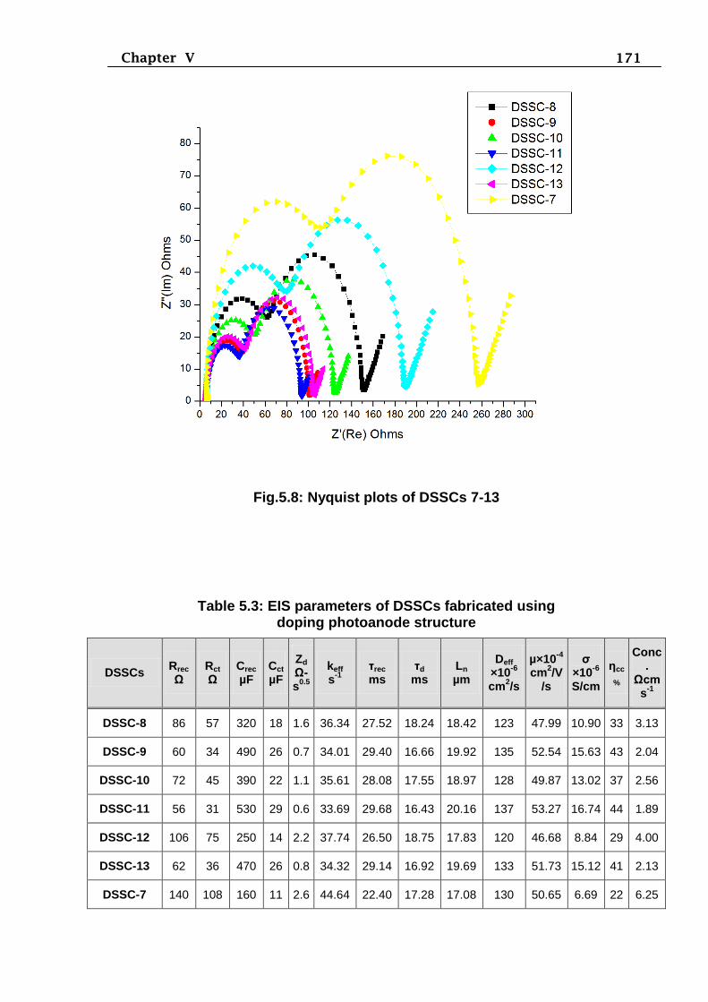
5.6 EIS characterization of DSSCs made with Al@TNPWs doping photoanode
Electron transport properties of DSSCs were investigated by EIS. Fig. 5.8
shows the Nyquist plots of DSSCs fabricated with different types photoanodes and
electrolytes. The internal impedances Rs, Rrec, Rct, Zd were determined from the
Nyquist plot and listed in Table 5.3. The other useful electrochemical parameters of
DSSCs, keff (rate of recombination of the electrons in the film), τrec (effective electron
life time), τd (electron transport time), Ln (electron diffusion length), Deff (effective
diffusion coefficient), µ (electron mobility), σ (electron conductivity), ηcc (electron
collection efficiency) and concentration of electrons in the TiO2/dye/electrolyte
interface was calculated and presented in Table 5.3.
From the Nyquist plots of DSSCs, it could be seen that first and third
semicircles are weak as compared the second semicircle. From the Fig. 5.8,
comparison of the middle semicircles of Nyquist plots of the DSSCs made with
different electrolytes indicates the decreased of the diameter in the order
DSSC-8>DSSC-10>DSSC-9>DSSC-11. This observation suggested that DSSC-11
contributed to the lowest charge transfer resistance at the photoanode/dye/electrolyte
interface as a result of the quasi-solid state electrolyte. When comparing the Nyquist
plots of DSSC-11 and DSSC-12, the Rrec value is increased in DSSC-12 because of
undoped Al photoanode. Likewise, when comparing the Nyquist plots of DSSC-11
and DSSC-13, the Rrec value is increased in DSSC-13 due to the absence of HfO2
blocking layer in the photoanode. The DSSC-7 showed the highest value of Rrec
among the other DSSCs as a consequence of sluggish electron transport. In the EIS
study, higher ηcc was achieved in DSSC-11 fabricated based on Al-doped TNPWs
with HfO2 blocking layer structure photoanode through quasi solid state electrolyte
as compared to the other cells. The DSSC-11 illustrated higher values of Crec, τrec, Ln,
Deff, µ, σ and ηcc as compared to other DSSCs. In addition, keff and concentration of
electrons in the photoanode/dye/electrolyte interface were lower values as compared
168 Chapter V
to the other DSSCs. Introducing cations as dopant on the surface of photoanode
materials exerts larger dipole moment that changes the interface energetic in an
actively more favourable way for electron transfer (Warson and Meyer, 2004).
Consequently, Al-doped TNPWs photoanode provided faster electron injection at the
photoanode/dye/electrolyte interface. Recombination rate was diminished because of
HfO2 layer could shield electron back flow through TNPWs to the electrolyte. In our
examination on the performance of Al-doped TNPWs photoanode structure-based
DSSCs hints that the essential improvement in electron injection efficiency and
thereby overall performance could be obtained by proper designing of dopant with
suitable band gap,optimal thickness of blacking layer.
The improved photoelectrochemical performance of DSSCs is attributed to
two main factors:(1) increased light harvesting efficiency caused by the large amount
of sensitizing dye D149 adsorbed on the large surface area of Al-doped TNPWs
composite and (2) increased electrical conductivity due to Al ions doped into the
TiO2 lattice at the divalent Ti2+
site, allowing electrons to move easily into the Al-
doped TiO2 conduction band. The optical response of material is largely determined
by its underlying electronic structure. The electronic properties of a material are
closely related to its chemical composition, its atomic arrangement, and its physical
dimension. The chemical composition of TiO2 can be altered by doping. It is
desirable to support the integrity of the crystal structure of the photocatalytic host
material and to produce favourable changes in electronic structure. As the Fermi
levels of Al are lower than that of TiO2, photo-excited electrons can be transferred
from conduction band (CB) of TiO2 to Al band, while photo-generated valence band
holes stay on the TiO2. These activities greatly reduce the possibility of electron-hole
recombination, resulting in proficient ηcc (Patel et al., 2008; Wang and Caruso,
2011).
169 Chapter V
The presence of dopant metal can act as an electron sink and significantly
decreased the electron transport time and improved mobility of photogenerated
electrons (Carneiro et al., 2009). In DSSC-11, the lower Rrec suggested that each
TNW made more difficult for an electron to jump outside the nanostructure than to
stay within the structure during diffusion; this explained the higher values of ηcc and
Deff. The De and τrec values of DSSC-13 with Hafnium oxide layer are shown to be
higher than those of DSSC-7 built with bare electrode. The higher De illustrated that
the TNPWs film becomes more conductive owing to the increased electron density in
the conduction band by introducing Hafnium oxide barrier. In addition, the elevated
τrec value of the by introducing Hafnium oxide also proved that the Hafnium oxide
layer formed on the TNPWs surface could effectively retarded the electron
recombination process between photoanode and electrolyte. Hence, the Al-doped
TNPWs with blocking layer photoanode with QSSE exhibited enhanced
photoelectrochemical behaviours in DSSC-11. In this photoelectrochemical system,
charge separation, transport and recombination strongly depend on the nanostructure
of the photoanode and nature of electrolytes.
Therefore, the DSSCs based on the Al-doped TNPWs film has the lower
values for Rrec, Rct and the longer electron lifetime, led to enhanced ηcc of the cell. In
the present investigation, D149 dye is used as the efficient sensitizer for DSSCs. The
Al-doped TNPWs photoanode demonstrated a successful photoelectrode within
DSSCs which keep the desired specific surface area for dye-molecule adsorption and
enough light-harvesting from prolonged light travelling. In addition, QSSE had
relatively high ambient ionic conductivity, intimate interfacial contact with Al doped
TNPWs-HfO2, and remarkable stability which led to higher efficiency as compared
to the other electrolytes. The ηcc improvement can result from retardation of
interfacial charge recombination and/or from possible upward shift of the CB edge
position of TiO2 due to development of a dipole at the interface of TiO2/metal oxide
170 Chapter V
(Law et al., 2006; Butler and Ginley, 1978; Diamant et al., 2004). The CB edge for
all composite photoanodes, by extension is the same leaving retardation of charge
recombination as the origin of the observed ηcc increase.
According to Fig.5.8, in DSSC-11, Al2O3 presented the highest blocking
ability for interfacial charge recombination because of its lowest Rrec, which also
resulted in the highest electron lifetime as determined from the EIS measurements.
The blocking ability of Al is most likely due to its higher CB edge position. It is
notable that the mechanism of charge transfer determining Rrec is via direct transfer
from the CB of TiO2 (Fabregat-Santiago et al., 2005). However, electrons may
recombine not only from the CB but also from localized intra band states as well as
surface states in the band gap (Fabregat-Santiago, 2005; Bisquert et al., 2004).
Therefore, it is also interesting to probe the region of lower Fermi levels (Zaban et
al., 2003). Thus, the EIS technique is employed as it allows us to monitor the kinetics
of recombination in the domain of low photo-voltages (Bisquert, et al., 2004; Zaban
et al., 2003].
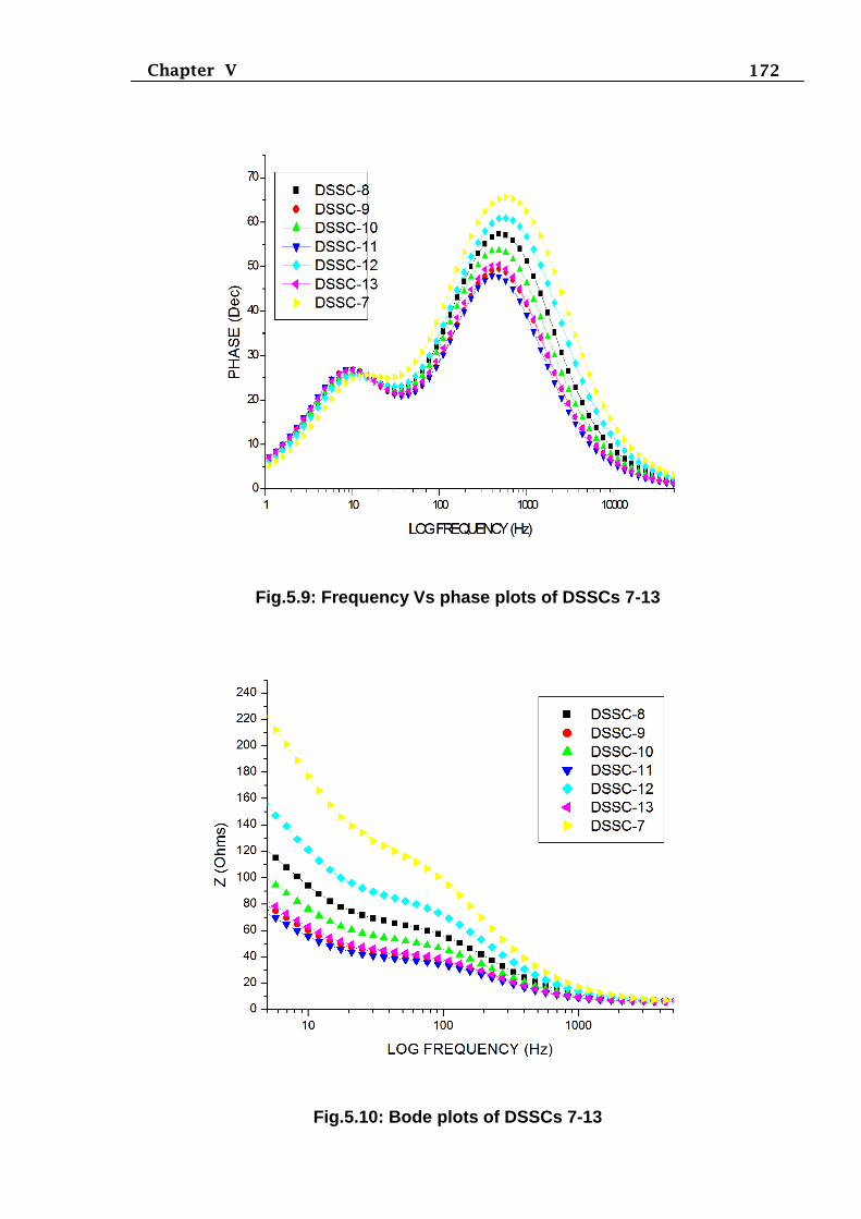
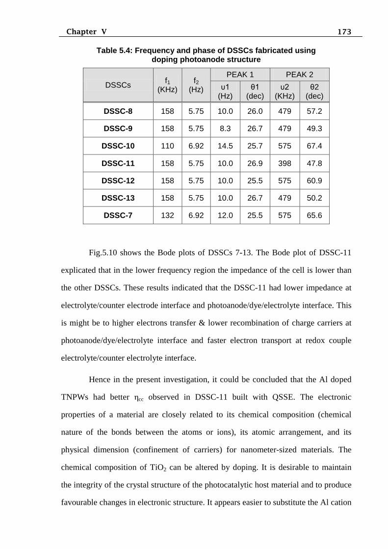
Fig.5.9 shows the frequency – phase plots of DSSCs 7-13. The characteristic
frequency peak of DSSC-11 in higher frequency regime shifted to lower frequency
region as compared to DSSCs. This result could be attributed to the higher electron
transport rate, electron diffusion coefficient and large surface area of doping
structure photoanode in the DSSC-11. These results indicated that the doping
photoanode DSSC-11 had fast electrons transport and lower recombination rate at
photoanode/dye/electrolyte interface and the same property leading to higher
photocurrent efficiency.
171 Chapter V
Fig.5.8: Nyquist plots of DSSCs 7-13
Table 5.3: EIS parameters of DSSCs fabricated using doping photoanode structure
DSSCs Rrec
Ω
Rct
Ω Crec
µF Cct
µF
Zd
Ω-s
0.5
keff s
-1
τrec
ms τd
ms Ln
µm
Deff
×10-6
cm2/s
µ×10-4
cm2/V
/s
σ ×10
-6
S/cm
ηcc
%
Conc.
Ωcms
-1
DSSC-8 86 57 320 18 1.6 36.34 27.52 18.24 18.42 123 47.99 10.90 33 3.13
DSSC-9 60 34 490 26 0.7 34.01 29.40 16.66 19.92 135 52.54 15.63 43 2.04
DSSC-10 72 45 390 22 1.1 35.61 28.08 17.55 18.97 128 49.87 13.02 37 2.56
DSSC-11 56 31 530 29 0.6 33.69 29.68 16.43 20.16 137 53.27 16.74 44 1.89
DSSC-12 106 75 250 14 2.2 37.74 26.50 18.75 17.83 120 46.68 8.84 29 4.00
DSSC-13 62 36 470 26 0.8 34.32 29.14 16.92 19.69 133 51.73 15.12 41 2.13
DSSC-7 140 108 160 11 2.6 44.64 22.40 17.28 17.08 130 50.65 6.69 22 6.25
172 Chapter V
Fig.5.9: Frequency Vs phase plots of DSSCs 7-13
Fig.5.10: Bode plots of DSSCs 7-13
173 Chapter V
Table 5.4: Frequency and phase of DSSCs fabricated using doping photoanode structure
DSSCs f1
(KHz)
f2 (Hz)
PEAK 1 PEAK 2
υ1 (Hz)
θ1 (dec)
υ2 (KHz)
θ2 (dec)
DSSC-8 158 5.75 10.0 26.0 479 57.2
DSSC-9 158 5.75 8.3 26.7 479 49.3
DSSC-10 110 6.92 14.5 25.7 575 67.4
DSSC-11 158 5.75 10.0 26.9 398 47.8
DSSC-12 158 5.75 10.0 25.5 575 60.9
DSSC-13 158 5.75 10.0 26.7 479 50.2
DSSC-7 132 6.92 12.0 25.5 575 65.6
Fig.5.10 shows the Bode plots of DSSCs 7-13. The Bode plot of DSSC-11
explicated that in the lower frequency region the impedance of the cell is lower than
the other DSSCs. These results indicated that the DSSC-11 had lower impedance at
electrolyte/counter electrode interface and photoanode/dye/electrolyte interface. This
is might be to higher electrons transfer & lower recombination of charge carriers at
photoanode/dye/electrolyte interface and faster electron transport at redox couple
electrolyte/counter electrolyte interface.
Hence in the present investigation, it could be concluded that the Al doped
TNPWs had better ηcc observed in DSSC-11 built with QSSE. The electronic
properties of a material are closely related to its chemical composition (chemical
nature of the bonds between the atoms or ions), its atomic arrangement, and its
physical dimension (confinement of carriers) for nanometer-sized materials. The
chemical composition of TiO2 can be altered by doping. It is desirable to maintain
the integrity of the crystal structure of the photocatalytic host material and to produce
favourable changes in electronic structure. It appears easier to substitute the Al cation
174 Chapter V
in TiO2 strucutre and it is more difficult to replace the O2-
anion with other anions
due to differences in charge states and ionic radii. The small size of the nanoparticle
is beneficial for the modification of the chemical composition of TiO2 due to the
higher tolerance of the structural distortion than that of bulk materials induced by the
inherent lattice strain in nanomaterials (Burda, et al., 2003; Chen, et al., 2003). In the
present investigation, Al doped TiO2 showed enhanced photocurrent due to the
compatible energy level between Al and TiO2. The presence of Al metal ion dopants
in the TiO2 matrix significantly influenced the charge carrier recombination rates and
interfacial electron-transfer rates.
In the present investigation, QSSE had relatively high ambient ionic
conductivity, intimate interfacial contact with Al doped TNPWs-HfO2, and
remarkable stability which led to higher efficiency as compared to the other
electrolytes. This may be attributed to the high dielectric constant and low viscosity
of the organic solvent. The stronger polarity of solvent with high dielectric constant
is beneficial to the enhancement of ionic dissociation in the QSSE, leading to the
higher conductivity (Wang Miao et al., 2006). Furthermore, the corresponding Jsc
value listed in Table 1 also have the same trend as the change of ionic conductivity
data. This indicated that the organic solvent have great effects on the performance of
QSSE solar cells. Fig. 5.11 shows time-dependent change in the PCE of DSSCs
made with different electrolytes through aging test. It was observed that the PCE of
the cell based on liquid electrolyte decreased immediately with increasing time and
after 30 days was close to zero. On the other hand, the PCE of the cell based on
quasi-solid state electrolyte containing PEG polymer decreased much slowly and
after 100 days still remained 5.4%, which kept 66% of its initial conversion
efficiency, because the addition of the polymer into the electrolyte changed the state
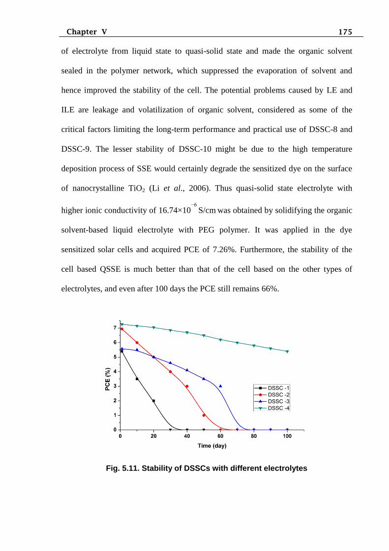
175 Chapter V
of electrolyte from liquid state to quasi-solid state and made the organic solvent
sealed in the polymer network, which suppressed the evaporation of solvent and
hence improved the stability of the cell. The potential problems caused by LE and
ILE are leakage and volatilization of organic solvent, considered as some of the
critical factors limiting the long-term performance and practical use of DSSC-8 and
DSSC-9. The lesser stability of DSSC-10 might be due to the high temperature
deposition process of SSE would certainly degrade the sensitized dye on the surface
of nanocrystalline TiO2 (Li et al., 2006). Thus quasi-solid state electrolyte with
higher ionic conductivity of 16.74×10⁻⁶
S/cm
was obtained by solidifying the organic
solvent-based liquid electrolyte with PEG polymer. It was applied in the dye
sensitized solar cells and acquired PCE of 7.26%. Furthermore, the stability of the
cell based QSSE is much better than that of the cell based on the other types of
electrolytes, and even after 100 days the PCE still remains 66%.
Fig. 5.11. Stability of DSSCs with different electrolytes
176 Chapter V
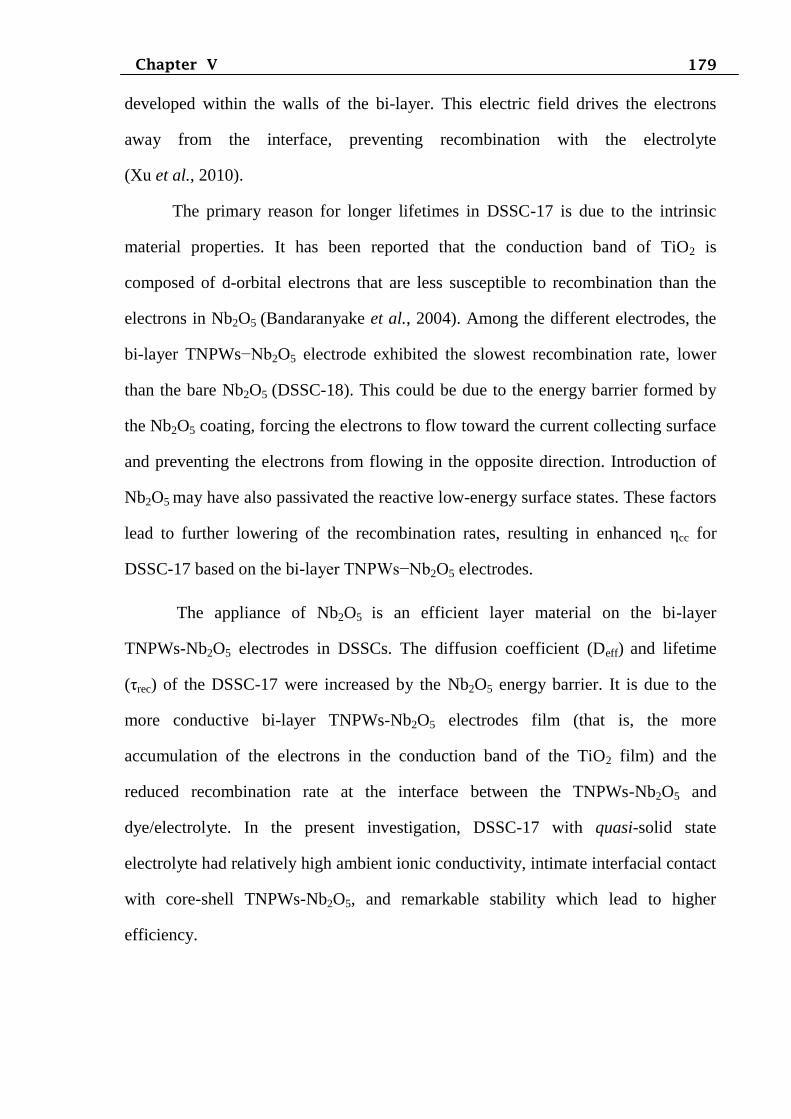
5.7 EIS characterization of DSSCs made with bi-layer photoanode
Nyquist plots of DSSCs made using bi-layer photoanode is shown in
Fig.5.12. From the Fig.5.12, comparing the middle semicircles of Nyquist plot of the
DSSCs made with bi-layer photoanode structure indicates the decrease of diameter in
the order DSSC-14>DSSC-16>DSSC-15>DSSC-17, suggesting that DSSC-17
contributed to the lowest charge transfer resistance at the photoanode/dye/electrolyte
interface. When comparing the Nyquist plots of DSSC-17 and DSSC-7, the Rrec
value increased in DSSC-7 due to uncoated Nb2O5 photoanode. When comparing the
Nyquist plots of DSSC-17 and 18, the Rrec value increased for DSSC-18 due to bare
Nb2O5 photoanode layer. The DSSC-7 shows the highest value of Rrec. In this study,
higher ηcc is achieved in DSSC-17 based on D149 sensitized TNPWs-Nb2O5 bi-layer
structure photoanode through quasi-solid state electrolyte as comparing to other
cells. The DSSC-17 made with novel photoanode illustrated higher values of Crec,
τrec, Ln, Deff, µ, σ and ηcc when comparing other DSSCs. In addition, keff and
concentration of electrons in the TiO2/dye/electrolyte interface were lower values
compared to other DSSCs.
The bi-layer TNPWs-Nb2O5 photoanode exhibited better electrochemical
behaviours when they are employed in dye-sensitized solar cells. In this photo
electrochemical system, charge separation, transport and recombination strongly
depend on the bi-layer structure of the photoanode. From EIS data it could be
concluded that for the cell containing TNPWs-Nb2O5 bi-layer, formation of a space
charge layer at the surface of the electrode effectively promoted the separation of
photo generated charge carriers and prevented recombination of the electron with the
hole carriers. In addition, the holes transported to electrolyte via the different
channel, which could prevented the charge recombination at the bi-layer TNPWs-
Nb2O5/redox electrolyte interfaces and led to the electrons diffusion and transport
177 Chapter V
become easy. Therefore, the DSSCs based on the composite core-shell TNPWs-
Nb2O5 film had the lower values for Rrec, Rct and the longer electron lifetime,
consequently leading to an enhanced conversion efficiency of the cell.
As revealed from Table 5.5, the presence of bi-layer TNPWs-Nb2O5 layer
increases the electron lifetime and makes the electron transfer more easily. In other
words, the charge transfer resistance in bi-layer TNPWs-Nb2O5 interfaces and
electron recombination are decreased, leading to a positive influence on the
improvement of solar cell performance. Hence with EIS investigation, it was showed
the enhanced electron transport properties, reduced charge recombination and
increased electron life-time which are imperative for higher solar cell performance
could be achieved in DSSC-17. Therefore, DSSCs fabricated with bi-layer
TNPWs-Nb2O5, which provided direct and enhanced charge transport while
minimizing charge recombination resulted in enhanced efficiency in bi-layer
TNPWs-Nb2O5 based DSSCs compared to other DSSCs. Use of bi-layer
nanostructure the Nb2O5 coating layer may build up an energy barrier at the
semiconductor/electrolyte interface and, thus, retard the reaction between the
photogenerated electrons and the redox species in electrolyte.
Instead of using only nanocrystalline TiO2 particle films, it has been
proposed that a bi-layer structure composed of light scattering layer and
nanocrystalline semi-transparent layer can improve photocurrent density
substantially due to the fact that the confinement of incident light by light scattering
particles can gain more photons (Ito, et al., 2006; Hore, et al., 2006). When light
collides with the large TiO2 particle having submicrometer size, the light scattered
strongly, this increased the path length of the incident light in the nanocrystalline
TiO2 films. Eventually, the scattering effect by introduction of the large TiO2
particles is expected to enhance the photocurrent density and thereby overall
178 Chapter V
conversion efficiency. The scattering effect is known to be dependent on size
(Vargas, 2000), refractive index (Hore, et al., 2006) and position
(Wang, et al., 2004), of the scattering particles.
The Deff and τrec values of the DSSC-17 shown to be higher than DSSC-7.
The higher Deff revealed that the TNPWs film becomes more conductive owing to
the increased electron density in the conduction band by introducing Tantalum oxide
barrier. The increased τrec value of the photoelectrode by introducing Hafnium oxide
also proved that the blocking layer formed on the TNPWs surface can effectively
retard the electron recombination process between nanocrystalline TiO2 and
electrolyte. The enhancement of the electron injection might be attributed to the shift
of conduction band edge of TiO2. Previously, it has been reported that the acidic
property of Nb2O5 shifted the TiO2 flat band energy potential (Efb) toward positive
values and increased the driving force for electron injection (determined as the
difference between Efb and the LUMO state of the dye), thereby enhancing the
electron injection efficiency. Here, in EIS spectra, the Nyquist plot revealed a large
semicircle in the frequency range between 1 mHz to 105 Hz. The size of the arc
depended on the concentration of I3− and on the rate of back-electron transfer at the
TiO2/electrolyte interface. The impedance spectrum was analyzed using an
equivalent circuit for the TiO2/electrolyte interface in the conductive state. The
recombination resistance (Rrec) is obtained by the curve of the large semicircle.
The EIS is sensitive to the interfacial electron flow in the electrode/electrolyte
interface. The EIS curves show the reduction peaks attributed to the
charging/discharging at the interface and the peak was shifted positively upon the
Nb2O5 coating. This result confirms the positive shift of the conduction band edge in
Nb2O5-coated TiO2 electrodes. The much larger τrec in the bi-layer DSSC-17 as
compared to DSSC-18 may be explained by an internal radial electric field that is
179 Chapter V
developed within the walls of the bi-layer. This electric field drives the electrons
away from the interface, preventing recombination with the electrolyte
(Xu et al., 2010).
The primary reason for longer lifetimes in DSSC-17 is due to the intrinsic
material properties. It has been reported that the conduction band of TiO2 is
composed of d-orbital electrons that are less susceptible to recombination than the
electrons in Nb2O5 (Bandaranyake et al., 2004). Among the different electrodes, the
bi-layer TNPWs−Nb2O5 electrode exhibited the slowest recombination rate, lower
than the bare Nb2O5 (DSSC-18). This could be due to the energy barrier formed by
the Nb2O5 coating, forcing the electrons to flow toward the current collecting surface
and preventing the electrons from flowing in the opposite direction. Introduction of
Nb2O5 may have also passivated the reactive low-energy surface states. These factors
lead to further lowering of the recombination rates, resulting in enhanced ηcc for
DSSC-17 based on the bi-layer TNPWs−Nb2O5 electrodes.
The appliance of Nb2O5 is an efficient layer material on the bi-layer
TNPWs-Nb2O5 electrodes in DSSCs. The diffusion coefficient (Deff) and lifetime
(τrec) of the DSSC-17 were increased by the Nb2O5 energy barrier. It is due to the
more conductive bi-layer TNPWs-Nb2O5 electrodes film (that is, the more
accumulation of the electrons in the conduction band of the TiO2 film) and the
reduced recombination rate at the interface between the TNPWs-Nb2O5 and
dye/electrolyte. In the present investigation, DSSC-17 with quasi-solid state
electrolyte had relatively high ambient ionic conductivity, intimate interfacial contact
with core-shell TNPWs-Nb2O5, and remarkable stability which lead to higher
efficiency.
180 Chapter V
Fig.5.12: Nyquist plots of DSSCs 14-18
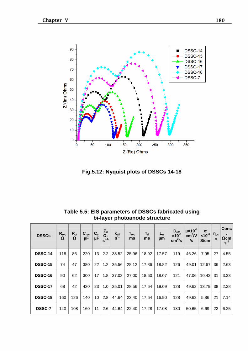
Table 5.5: EIS parameters of DSSCs fabricated using bi-layer photoanode structure
DSSCs Rrec
Ω
Rct
Ω Crec
µF Cct
µF
Zd
Ω-s
0.5
keff s
-1
τrec
ms τd
ms Ln
µm
Deff
×10-6
cm2/s
µ×10-4
cm2/V
/s
σ ×10
-6
S/cm
ηcc
%
Conc.
Ωcms
-1
DSSC-14 118 86 220 13 2.2 38.52 25.96 18.92 17.57 119 46.26 7.95 27 4.55
DSSC-15 74 47 380 22 1.2 35.56 28.12 17.86 18.82 126 49.01 12.67 36 2.63
DSSC-16 90 62 300 17 1.8 37.03 27.00 18.60 18.07 121 47.06 10.42 31 3.33
DSSC-17 68 42 420 23 1.0 35.01 28.56 17.64 19.09 128 49.62 13.79 38 2.38
DSSC-18 160 126 140 10 2.8 44.64 22.40 17.64 16.90 128 49.62 5.86 21 7.14
DSSC-7 140 108 160 11 2.6 44.64 22.40 17.28 17.08 130 50.65 6.69 22 6.25
181 Chapter V
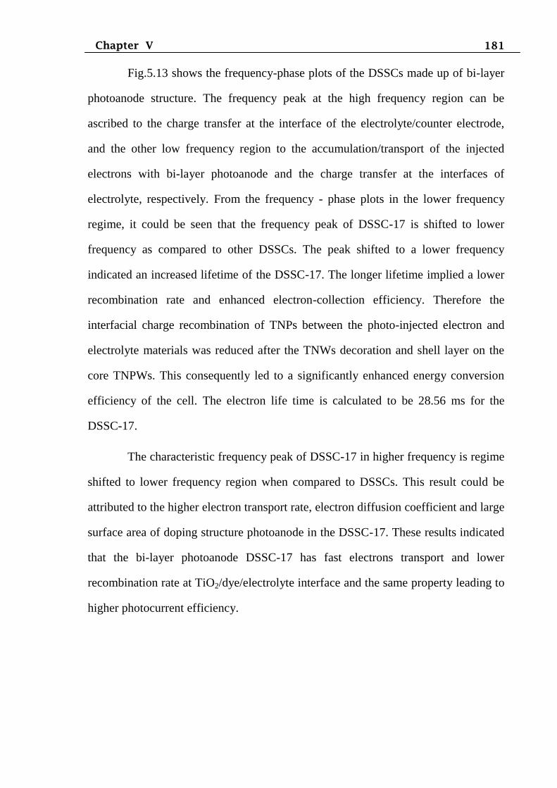
Fig.5.13 shows the frequency-phase plots of the DSSCs made up of bi-layer
photoanode structure. The frequency peak at the high frequency region can be
ascribed to the charge transfer at the interface of the electrolyte/counter electrode,
and the other low frequency region to the accumulation/transport of the injected
electrons with bi-layer photoanode and the charge transfer at the interfaces of
electrolyte, respectively. From the frequency - phase plots in the lower frequency
regime, it could be seen that the frequency peak of DSSC-17 is shifted to lower
frequency as compared to other DSSCs. The peak shifted to a lower frequency
indicated an increased lifetime of the DSSC-17. The longer lifetime implied a lower
recombination rate and enhanced electron-collection efficiency. Therefore the
interfacial charge recombination of TNPs between the photo-injected electron and
electrolyte materials was reduced after the TNWs decoration and shell layer on the
core TNPWs. This consequently led to a significantly enhanced energy conversion
efficiency of the cell. The electron life time is calculated to be 28.56 ms for the
DSSC-17.
The characteristic frequency peak of DSSC-17 in higher frequency is regime
shifted to lower frequency region when compared to DSSCs. This result could be
attributed to the higher electron transport rate, electron diffusion coefficient and large
surface area of doping structure photoanode in the DSSC-17. These results indicated
that the bi-layer photoanode DSSC-17 has fast electrons transport and lower
recombination rate at TiO2/dye/electrolyte interface and the same property leading to
higher photocurrent efficiency.
182 Chapter V
Fig.5.13: Frequency Vs phase plots of DSSCs 14-18
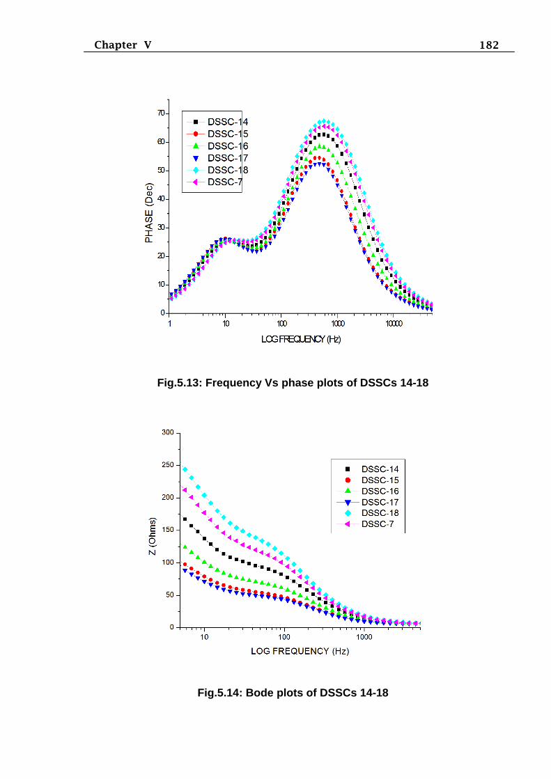
Fig.5.14: Bode plots of DSSCs 14-18
183 Chapter V
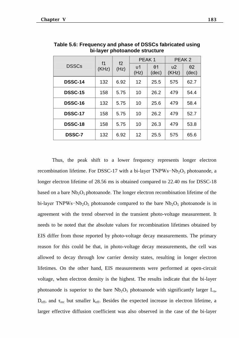
Table 5.6: Frequency and phase of DSSCs fabricated using bi-layer photoanode structure
DSSCs f1
(KHz)
f2 (Hz)
PEAK 1 PEAK 2
υ1 (Hz)
θ1 (dec)
υ2 (KHz)
θ2 (dec)
DSSC-14 132 6.92 12 25.5 575 62.7
DSSC-15 158 5.75 10 26.2 479 54.4
DSSC-16 132 5.75 10 25.6 479 58.4
DSSC-17 158 5.75 10 26.2 479 52.7
DSSC-18 158 5.75 10 26.3 479 53.8
DSSC-7 132 6.92 12 25.5 575 65.6
Thus, the peak shift to a lower frequency represents longer electron
recombination lifetime. For DSSC-17 with a bi-layer TNPWs−Nb2O5 photoanode, a
longer electron lifetime of 28.56 ms is obtained compared to 22.40 ms for DSSC-18
based on a bare Nb2O5 photoanode. The longer electron recombination lifetime of the
bi-layer TNPWs−Nb2O5 photoanode compared to the bare Nb2O5 photoanode is in
agreement with the trend observed in the transient photo-voltage measurement. It
needs to be noted that the absolute values for recombination lifetimes obtained by
EIS differ from those reported by photo-voltage decay measurements. The primary
reason for this could be that, in photo-voltage decay measurements, the cell was
allowed to decay through low carrier density states, resulting in longer electron
lifetimes. On the other hand, EIS measurements were performed at open-circuit
voltage, when electron density is the highest. The results indicate that the bi-layer
photoanode is superior to the bare Nb2O5 photoanode with significantly larger Ln,
Deff, and τrec but smaller keff. Besides the expected increase in electron lifetime, a
larger effective diffusion coefficient was also observed in the case of the bi-layer
184 Chapter V
photoanode. The reason for large Deff could be due to the passivation of the low
energy Nb2O5 surface trap states. These results explain the improved photovoltaic
performance of the bi-layer TNPWs−Nb2O5 photoanode as compared to the bare
Nb2O5 photoanode.
Fig.5.14 shows the Bode plots of DSSCs 14-18. The Bode plots of DSSCs
explicated that in the lower frequency region the impedance of the cell is higher than
the higher frequency region. These results indicated that the DSSC-17 has lower
impedance at electrolyte/counter electrode interface and photoanode/dye/electrolyte
interface when compared to other DSSC. This is due to higher electrons transfer &
lower recombination of charge carriers at photoanode/dye/electrolyte interface and
faster electron transport at redox couple electrolyte/counter electrolyte interface. In
DSSCs transport of charge carriers is limited by trapping-detrapping processes in
which both energy and morphological disorder play a role. Furthermore, in these
devices, the electron transport is strongly coupled with charge transfer to external
electron acceptors (recombination). This coupling determines the collection
efficiency of the device, which is the parameter to optimize for efficient production
of energy.
From the EIS results of DSSCs, it could be concluded that in order to get
better photocurrent efficiency, the photo anode materials must have (i) mesoporosity
and large surface area allow anchoring a large amount of dye molecules which
enhances the absorption cross-section, (ii) larger density of states in metal oxides
than the molecular orbital of dye allows faster injection of electrons from the dye to
the metal oxide. At the same time, the detrimental factors are (i) inefficient electrical
transport through nanocrystalline network and (ii) charge recombination within the
materials and also with the electrolyte. Inefficient electrical transport in
nanostructured metal oxide semiconductors arise from the trapping and detrapping of
185 Chapter V
electrons at the surface atomic states in the electronic band. The surface atoms are a
large fraction in nanostructured materials, so as the trap density. Trapping and
detrapping reduced the kinetic energy of the flowing electrons, which ultimately
results in inferior cell performance.
Various morphologies and approaches, such as doping, bi-layer, core/shell
structure, have been explored in the present study to enhance the electrical transport
properties. One dimensional morphology showed great promise in enhancing the
electrical transport properties. In the present investigation, one-dimensional TNWs
synthesized through hydrothermal method increased the electron life time and
allowed enhanced charge collection efficiency in DSSCs. Doping of Al in TNPWs is
found to be beneficial in increasing the photocurrent efficiency.
In the present investigation, the best performing DSSC-4 fabricated with the
organic dye D149 sensitized TNPWs/ZrO2 core-shell photoanode, quasi-solid state
electrolyte and cobalt sulfide counter electrode. Most likely the dye molecules form a
monolayer on the surface of shell layer of ZrO2 photoanode and aggregation seems to
be insignificant. Efficient sensitization and better absorption properties of D149
sensitizer are the key factors for its higher performance with respect to the indigo
carmine dye tested.
Taking into account that one of the most interesting properties of TiO2 is its
flexibility in synthesis and morphology, the influence of the semiconductor
morphology on the performance of TiO2 based solar cells has been studied. A
comparative study of D149 sensitized TiO2 electrodes based on core-shell, doping
and bi-layer have been carried out. A significant conclusion of this study is that the
performance of the one-dimensional nanostructures studied here is not limited by a
low light harvesting as could have been expected as a consequence of the relatively
low surface area. Nanowire based solar cell performance seems to be limited by poor
186 Chapter V
injection from the dye to the nanowires and/or strong recombination. Nanoparticles
deposited on the surface of the nanowires decreased significantly electron
recombination and lead to an improvement of the photovoltage and fill factor of the
cells and of the overall performance of the devices. This fact strongly suggests that
surface modification may significantly improve the performance of the
electrodeposited nanowire studied.
Comparative experiments reported on metal-free dyes emphasize the
importance of improving the photovoltaic performance by suitable molecular
engineering. The unambiguous enhancement of photopower-conversion efficiency
was examined by extending the length of the alkyl chain on the sensitizer with a
hierarchical photoelectrode composed of aggregated TiO2 nanoparticles. Although
the efficiency of DSSCs cannot compete with metal based sensitizers presently, we
hope that these investigations will shed light on the development of organic
sensitizers and can be used in the TiO2 nanostructure optimization for the proposed
solar cell applications. This investigation strongly suggested that the performance of
DSSCs based on organic dye sensitizer D149 could be improved. In the present
investigation the higher photocurrent efficiencies of D149 sensitizer suggested that
the appropriate HOMO and LUMO energy level of the dye with photoanode and
electrolyte energy levels (Ooyama and Harima, 2009).
Organic dyes have been widely employed as sensitizers for TiO2
nanomaterial to improve its optical properties, i.e., in dye-sensitized nanocrystalline
solar cells (DSSCs). The D149 organic dye linked to TiO2 nanoparticle surfaces via
functional groups by various interactions between the dyes and the TiO2 nanoparticle
substrate: (a)covalent attachment by directly linking groups of interest or via linking
agents, (b) electrostatic interactions via ion exchange, ion-pairing, or donor-acceptor
interactions, (c) hydrogen bonding, (d) van der Waals forces, etc. Carboxylic and
187 Chapter V
phosphonic acid derivatives react with the hydroxyl groups to form esters, while
amide linkages are obtained via the reaction of amine derivatives and dicyclohexyl
carbodiimide on TiO2. The most common and successful functional groups are based
on carboxylic acids. The interfacial charge separation between the adsorbed dyes and
TiO2 nanomaterials involves one of three mechanisms, which differ by the nature of
the donor that transfers the electron to the semiconductor: (1) excited state; (2)
reduced state; or (3) molecule-to-particle charge-transfer complex (Li, et al., 2009).
Ultrafast electron transfer from metal-to-ligand charge transfer (MLCT)
excited states to anatase TiO2 is the most common category in dye-sensitized TiO2.
The mechanism of the dye sensitization of TiO2 nanoparticles normally involves the
excitation of the dye and the charge transfer from the dye to TiO2 nanoparticles. The
low-lying MLCT and ligand-centered (ð-ð*) excited states of these complexes are
fairly long-lived, allowing them to participate in electron transfer processes. As an
efficient photosensitizer, the dye has to meet several requirements. First, the dye
should have high absorption efficiency and a wide spectral range of coverage of light
absorption in the visible, near-IR, and IR regions. Second, the excited states of the
dye should have a long lifetime and a high quantum yield. Third, the dye should have
matched electronic structures for the ground and excited states with TiO2
nanoparticles to ensure the efficient charge transfer between them; that is, the energy
level of the excited state should be well matched to the lower bound of the
conduction band of TiO2 to minimize energetic losses during the electron-transfer
reaction (Li, et al., 2009).
Quasi-solid state electrolyte is an alternative to liquid electrolytes in order to
improve the stability of electrolytes and thus that of their DSSCs. Quasi-solid state
electrolyte, especially in the gel state, have been a research hotspot due to their high
ionic conductivity, excellent thermal stability and long-term stability of the DSSCs
188 Chapter V
based on them. The concentration of iodide salts significantly influences the ionic
conductivity of quasi-solid state electrolyte and the performance of the DSSCs
because of viscosity and bond formation between the cation and atoms of polymer
chains. Higher polymer concentration leads to a decrease in ionic conductivity due to
smaller polymer cages and for polymer blend quasi-solid state electrolyte, the ionic
conductivity decreases as the concentration of the lower-conductivity and higher-
viscosity polymer increases. In the present investigation, quasi-solid state
electrolytes exhibited highest transport of charge carriers when compared to ionic
liquid electrolyte.
One way to reduce the cost of the DSSC is to use less expensive counter
electrode materials. The electron transfer rate of redox couples has to depend
strongly on the electrode material. From the present analysis it could be concluded
that the dependence of the surface area of cobalt sulfide electrodes on the catalytic
activity for reduction of redox couple at the counter electrodes is higher when
compared to copper sulfide electrode. The catalytic activity sites in cobalt material
are located on the crystal edges and the activity of cobalt is therefore expected to
increase with increasing surface area of the counter electrodes.
For DSSC to have a real impact in the commercial domain, mastering the
factors that control the electron injection and transport at the materials interfaces is
vital. The development of new dye materials, transport materials, electrolytes, hole
transport materials has countenanced interfaces to be formed efficiently and in many
cases elegantly. The electrons are injected across the dye/metal oxide interface into
metal oxide, a process that is controlled by the energetics between dye and metal
oxide, electronic states and chemical nature of metal oxides, and process condition.
Although we have not given any direct correlation between chemical property of the
metal oxides and device performance in this work.
189 Chapter V
1D nanomorphologies render controlled (surface focused) unidirectional
electron pathway in the metal oxides. It will be particularly important to explore in-
depth and reveal all the factors that are barriers for 1D nanostructured materials and
their interfaces with dye and electrolyte from sterling performance. Larger area of
interface is necessary for more exciton separation, which could be achieved in 1D
nanowires even for a limited film thickness nonetheless we cannot rule out the
possibility that increasing the interface area to a certain extent could also lead to high
interfacial recombination. Thus it is important to carefully form the interface with
right combination of donor and acceptor materials, and control the interface to yield
complete dissociation of electron and hole under optimized operating condition.
DSSCs nowadays pay attention, not only to obtain higher solar-current
conversion efficiency, and also by their potential for being cost effective, and more
stable for longer period of time. Caution must be exercised when more materials are
involved in DSSCs as there will be trouble for scaling up the cell design and
controlling the manufacturing the cost. Researchers therefore currently concentrate
on maximizing the performance of DSSCs by developing multifunctional engineered
materials-based interfaces as well as reducing the complexity in the cell design to
make DSSCs entirely a commercially viable.
Low cost is a very important benefit of producing dye sensitized solar cells
compared to the widely used conventional Si-solar cell. Moreover, enhanced dye-
sensitized solar cell efficiency would provide enormous economical advantages.
Recently, nano-sized TiO2 powders have been used as a working electrode for dye-
sensitized solar cells (DSSC) due to a higher efficiency than any other metaloxide
semiconductor. However, as reported, the best TiO2 solar cell efficiency could hardly
reach 10% . Therefore, photo-generated charge recombination should be prevented
for enhanced efficiency because solely enlarging the oxide electrode surface area is
not sufficient. A very thin metal oxide layer has often been applied, forming a
190 Chapter V
passive layer and preventing injected dye electron recombination between TiO2 and
electrolyte.
In recent years, research has focused on minimising charge recombination
processes. One approach involves the formation of a shell around the core
semiconductor by coating the semiconductor with a metal oxide that has a higher
conduction band than the semiconductor itself. This coating allows the photo injected
electrons generated upon photo-excitation of the dye by incident light to tunnel
through the shell to the semiconductor core and, subsequently, into the conducting
oxide layer simultaneously creating an energy barrier for charge recombination.
When the electrodes were constructed into DSSCs and had their photovoltaic
performance tested under the full visible light spectrum the efficiencies were found
to vary substantially. The pure TiO2 electrode used in this study had a relatively low
performance due to the opaque nature of the cells. The ZrO2 coating on the TiO2
electrodes produced a consistent trend in efficiencies. All ZrO2-coated TiO2
electrodes performed to a higher efficiency to that of the uncoated TiO2 electrodes. In
this work, the effect of a ZrO2 shell on the TiO2 core semiconductor on the efficiency
of DSSC has been ascertained. It has been found that the thin ZrO2 shell performed
the most efficiently out of the modified electrodes. The efficiency of thin ZrO2-
coated TiO2 electrode was remarkably better than the uncoated TiO2 exibiting
efficiencies of 8.03% and 3.98% respectively.
There are several electron transfer models such as diffusion, hopping,
tunneling, and a trap-detrap mechanism. The photo-generated electron can more
easily flow through surface defects toward TCO rather than bulk because the trap-
detrap transfer mechanism and diffusion can be more effectively operated at the
surface. In the present investigation, TEM image shows the Al dopes TNPWs had
less surface defect results in more compact dye molecule absorption for equal
soaking time. Densely absorbed and aggregated dye molecules inhibit tri-iodide ions
191 Chapter V
reaching the TiO2 surface due to steric hindrance. Therefore, direct recombination of
excited and transferred dye electrons with tri-iodide ion was greatly decreased by
doping Al on TiO2 semiconductor. When electrons recombine at the TiO2/electrolyte
interface, not only would a decrease of Voc result from the reduction of ions but also
a photocurrent degradation occurs due to less electrons transferred to the TCO
electrode. It was found that dye-sensitized solar cell characteristics fabricated with
AL doped TiO2 were remarkably better than those with undoped TiO2. Al-doping
results in a higher overall performance in comparison with DSSCs containing un-
doped DSSCs.
In the present investigation, after introducing Nb2O5 blocking layer, the
increase of interfaces would result in the increase of trap density, especially related
with Nb2O5 new phases. It is some difficult for electrons to jump across the potential
barrier to reach ITO phases because the potential of the Nb2O5 blocking layer.
However, the electron injection can occur through electron tunnelling because of the
µm-sized thickness of the Nb2O5 blocking layer. According to the Eqn. (5.5) the Ln
(diffusion length) in DSSC-17 with Nb2O5 blocking layer becomes higher than that
of non-blocking DSSC-7. The longer Ln is preferable for the improvement of
performance of DSSCs. Since the thickness of blocking layer should play a key role
in obtaining desirable value of Deff, we need to control and optimize the thickness of
blocking layer to get both larger Voc and diffusion length (Ln).
Thin Nb2O5 films as a novel potential scattering layer between ITO and TiO2
nanocrystaline film have been employed in ionic liquid electrolyte cells, improving
Voc and finally giving a better conversion efficiency of the dye-sensitized TiO2 solar
cells using hydrophobic dye D149. The main reason for the improvement in
performance of the DSSCs may be due to an electronically controlled barrier formed
between nano-TiO2 film and electrolyte, which can suppress the leakage of the
electron at this interface effectively, resulting especially in the increment of open
192 Chapter V
circuit voltage of QSSE-based DSSCs. Impedance spectroscopy reveals that after the
construction of the potential blocking layer, it can greatly increase shunt resistance
and decrease the series resistance to favorable extent, leading to the unidirectional
charge transport at the interfaces of ITO–photoanode/dye/ electrolyte. In addition,
such kind of the structured TNPWs- Nb2O5 bi-layer electrode can be more effective
on quasi solid state electrolyte investigated in this work partly because of
minimization of the void between ITO and nano-TiO2. Electron leakage suppression
at interfaces in DSSC is so important that we should pay attention to this during the
manipulation of unidirectional electron transporting in order to get higher
performance in DSSCs.
D149 is an aromatic heterocyclic compound have been extensively used in
designing new metal-free sensitizers. Assimilation of these moieties into the dye
molecular framework often extends the p-conjugation (towards the red side of the
visible spectra) as well as the electron-donating ability and thus helps to improve the
efficiency. The IPCE covers the entire visible region of the spectrum with 90% at the
526 nm region, resulting in a high Jsc value of 19 mA/cm2 being observed. The D149
organic dye sensitizer based on a D-A configuration in which indoline is used as an
electron donor, benzothiadiazole as an auxiliary acceptor, with thiophene moiety a
linker and cyanoacrylic acid as an anchoring unit cum acceptor. The additional
acceptor benzothiadiazole unit adjacent to the donors in a p-conjugation has several
advantages, such as improving the distribution of donor electrons to enhance the
photostability of indoline compounds, red shifting the absorption spectra into the
NIR region and weakening the deprotonation effect on a TiO2 film, beneficial to light
harvesting, as well as optimizing the match in energy levels to get the maximum
photon-to electricity conversion.
A quasi-solid state electrolyte is an effective material that can circumvent the
problems in dealing with the liquid component, such as the complicated sealing of
193 Chapter V
DSSCs. The quasi-solid state electrolyte can be formed by adding polymer matrix
and ionic liquid electrolyte. One of the questions accompanying the quasi-solid state
electrolyte is how to fill the pores inside the mesoporous photoanode. If a part of the
photoanode leaves empty, the empty part becomes the source for the electron–hole
recombination and the parasitic current. An effective method to fill the pores
completely is to employ in situ polymerization.
The quasi-solid state, or gel state, is a particular state of matter, neither liquid
nor solid, or conversely both liquid and solid. Generally, a quasi-solid-state
electrolyte is defined as a system which consists of a polymer network (polymer
host) swollen with liquid electrolytes. Owing to its unique hybrid network structure,
quasi-solid-state electrolytes always possess, simultaneously, both the cohesive
property of a solid and the diffusive transport property of a liquid. Namely, quasi-
solid-state electrolyte show better long-term stability than liquid electrolytes do and
have the merits of liquid electrolytes including high ionic conductivity and excellent
interfacial contact property. Quasi-solid state electrolytes are usually prepared by
incorporating a large amount of a liquid electrolyte into organic monomer or polymer
matrix, forming a stable gel with a network structure via a physical or chemical
method. The quasi-solid-state electrolyte formed via physical cross-linking is called
“entanglement network”, which is thermo-reversible (thermoplastic). In the present
investigation, QSSE exhibited better performance in the charge transport in the
DSSCs.
In the present work, CoS have been used as electrocatalysts on the counter
electrode. Nanocrystalline platinum is the most precious of all electrocatalysts but is
not considered a good choice of a catalyst in DSSCs due to over cost. Metal sulfides
are considered a good choice. The present work, supports the existing trends, opts for
the employment of CoS as electrocatalysts and proposes some easy procedures for
their deposition on transparent conductive electrodes. The values of the contact
194 Chapter V
resistance Rs, which also includes the sheet resistance of the electrodes themselves.
Rs values were relatively small. Their variations reflect the quality of the ohmic
contact with the electrodes, which was the best in the case of cobalt sulfide. Charge-
transfer resistance Rct at the electrode/electrolyte interface greatly varied from one
electrode to the other. The EIS results showed CuS is the material offering the
smallest charge-transfer resistance and it is expected to offer the best solar cell
functionality.
EIS, describing electron transport and charge recombination in nanocrystalline
titania films in terms of continuity equations for the conduction band and the trap
states, which allows an interpretation of spectra of DSSCs operated in the open
circuit under illumination. In the present investigation reliable values of the
parameters related to electron transport and recombination, such as keff, Rrec, Rct and
the effective diffusion coefficient of electrons, Deff were determined simultaneously
from the working state of solar cells when careful analysis of the spectra of EIS
measured under the open circuit voltage under the various experimental conditions
was done based on the information obtained by classification and clarification of
characteristics of the impedance equation.
(1) Reliable values of the parameters relating to electron transport in dye-
sensitized solar cells can be determined from the spectra measured by
electrochemical impedance spectroscopy when careful analysis of the measured
spectra is done based on the guidelines from the classification and clarification of the
characteristics of the impedance equations of the photoanode. Reliable parameter
values provide the fundamental information for improving the cell efficiency.
(2) A high electron diffusion coefficient, Deff, a low recombination rate
constant, keff, a much higher recombination resistance, Rrec, than the electron
diffusion resistance, Rct, and a high electron density, ns, are the requisites for highly
efficient dye-sensitized solar cells.
195 Chapter V
5.8 Conclusions arrived from this chapter
DSSCs constructed using novel photoanode structures, namely core-shell
(TNPWs/ZrO2), doping (Al@TNPWs) and bi-layer (TNPWs-Nb2O5) with
D149 sensitizer, different types of electrolytes (LE, ILE, SSE & QSSE) and
cobalt sulfide counter electrode. Out of these structures, core-shell
photoanode structure DSSC-4 exhibited superior ηcc is the best one.
In DSSC-4, the values of τrec,Ln, Deff, µ, σ and ηcc are higher than other
DSSCs. Stablity of DSSCs 4, 11 and 17 fabricated with QSSE is higher than
DSSCs made with other types of electrolytes.
The surface modification namely core-shell (TNPWs/ZrO2), doping
(Al@TNPWs) and bi-layer (TNPWs-Nb2O5) can possibly (i) build an energy
barrier at the semiconductor/electrolyte interface to retard the electron
transfer to the electrolyte and (ii) reduce the density of surface traps, which
are considered to be the recombination centers.
Scattering of the incident light within the photoanode due to core-shell
(TNPWs/ZrO2), doping (Al@TNPWs) and bi-layer (TNPWs-Nb2O5)
strucutrues also helps in enhancing the light harvest by making more light
available for absorption by dye molecules adsorbed on the film.
To improve PCE of DSSCs, the multilayer microstructure of the
semiconductor nanocrystalline TiO2 films is optimized. Core-shell
(TNPWs/ZrO2), doping (Al@TNPWs) and bi-layer (TNPWs-Nb2O5) layers
of larger pore-size films and light-scattering particles with the desirable
thickness are being employed to high efficiency DSSCs.
D149 sensitizer, quasi-solid state electrolyte and cobalt sulfide counter
electrode were demonstrated better results of the photo-current efficiency.
HfO2 is an efficient blocking layer in the photoanode structure.
EIS technique precisely measured internal mechanism of the DSSCs.