Cart3D howto - Rocket Plumes...Cart3D howto - Rocket Plumes Problem statement Given: •Freestream...
3
Cart3D howto - Rocket Plumes Problem statement Given: • Freestream Mach number, M ∞ • Altitude (ρ ∞ , p ∞ , a ∞ , etc.) • Load factor (vehicle acceleration), n • Nozzle geometry, (Areas: A p , A t , A e ) Find: (ρ p , u p , v p , w p , p p ) • Non-dimensional primitive variable state vector to specify conditions at the plenum boundary face using flowCart’s SurfBC tag. HowTo: Mach numbers: Assuming that the flow is choked at the throat, and knowing the areas at the plenum, throat and exit, compute the Mach number at the plenum face using: eq. (1) So from the geometry Ap, At, and Ae, you now also have Me and Mp. Notice that Mp will be non-zero, the “plenum” conditions are not stagnation conditions.(You can see this equation in action using NASA Glen’s on-line nozzle simulator ). Reference quantities: Using the standard atmosphere, (or similar) you can then look up for your desired altitude. Thrust: Knowing the load factor, n, of the vehicle’s acceleration and its mass you can compute the amount of thrust the engine needs to produce: eq. (2 ) Thrust = mass * n * g Specifying Power BCs for Rocket Plumes Simulation of Space Shuttle Launch Vehicle (SSLV) with power boundary conditions for plumes of 2 Solid Rocket Boosters (SRBs) and 3 Space Shuttle Main Engines (SSMEs). BCs for all 5 engines were modeled by specifying plenum conditions and the flow was allowed to expand through the throats and nozzle bells. Detail of engines showing view of engine bells and cross section of engines with plenum, throat, and bells.
Transcript of Cart3D howto - Rocket Plumes...Cart3D howto - Rocket Plumes Problem statement Given: •Freestream...
Cart3D howto - Rocket Plumes
Problem statement
Given:
• Freestream Mach number, M∞ • Altitude (ρ∞, p∞,a∞,etc.)• Load factor (vehicle acceleration), n• Nozzle geometry, (Areas: Ap,At,Ae)
Find: (ρp,up,vp,wp, pp)
• Non-dimensional primitive variable state vector to specify conditions at the plenum boundary face using flowCart’s SurfBC tag.
HowTo:Mach numbers: Assuming that the flow is choked at the throat, and knowing the areas at the plenum, throat and exit, compute the Mach number at the plenum face using:
eq. (1)
So from the geometry Ap, At, and Ae, you now also have Me and Mp. Notice that Mp will be non-zero, the “plenum” conditions are not stagnation conditions.(You can see this equation in action using NASA Glen’s on-line nozzle simulator).
Reference quantities: Using the standard atmosphere, (or similar) you can then look up
for your desired altitude.
Thrust: Knowing the load factor, n, of the vehicle’s acceleration and its mass you can compute the amount of thrust the engine needs to produce:
eq. (2 ) Thrust = mass * n * g
Where g is the acceleration due to gravity (e.g. 9.81m/sec2). So, if you’re accelerating at 2g’s (load factor of n = 2) you can compute how much thrust you need to produce to accelerate a rocket with a given mass. If you have more than one engine, divide the needed thrust up among the number of engines.
Using the exit mach number, Me, from eq.(1) and the thrust from (eq.2) along with the reference quantities, you can get the pressure at the nozzle exit, pe.
eq. (3) pe =
Thrust+Aep!
Ae(1+ "M2e
“Plenum face” Conditions: Pressure, temperature and density at the plenum face can now be computed using isentropic flow, and the perfect gas relations, working up and downstream from the throat. Remember, these are not stagnation conditions, but conditions in a plenum of finite cross-sectional area.
eq. (4) pp = pe
(1+ !!12 M2
e)!
!!1
(1+ !!12 M2
p)!
!!1
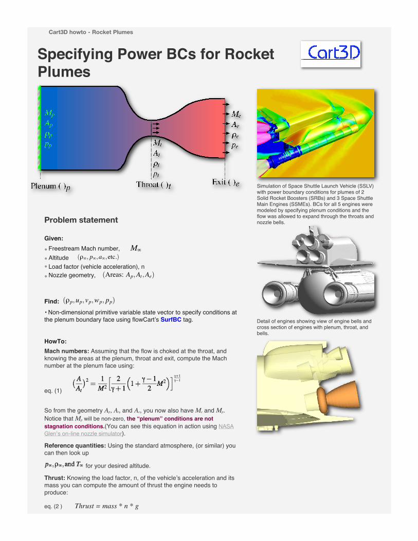
Taking the burn temperature as the stagnation temperature, To, we can get the temperature at the plenum-boundary face. Typical burn temps for oxy-hydrocarbon fuels are around 2800-3800 K.
eq. (5)
Below I tabulated flame temperatures for a few common specific liquid rocket propellents at fixed mixture ratios. There are much more complete tables on the web.
With pressure and temperature, we can get a perfect-gas plenum-face density.
eq. (6) where R is the gas constant of the working fluid.
Rair = Runiv/(molecular_weight air)R_univ = 8.3143 Joules/mole/Kmolecular_weight air = 28.964 gm/moleRair = 287.05 Joule/Kg/K
Non-dimensionalization: The SurfBC tag in flowCart’s input file <input.cntl> asks you to input non-dimensional values, ( )*, for the plenum-face state-vector.
eq. (7)
Choice of Gamma: The ratio of specific heats, gamma, is 1.4 for air, or for mixtures of other diatomic gasses. For combustion products of oxy-hydrocarbon fuels, its usually about 1.2, and gamma 1.2 can give pretty good nozzle designs. Real rockets are designed using finite-rate chemistry simulations where even an “effective gamma” can’t really be defined. In any event, we’re going to need to pick a gamma to use in setting your plenum-face conditions. One way to do this is to match the thrust you need to produce and to work out the appropriate “diatomic cold-flow equivalent plenum-face state” to produce the thrust you need. However, in general, a nozzle designed for hot real-gas conditions isn’t going to behave the same when perfect gas is used as the working fluid. By simplifying the problem for perfect gas, you’re going to have to decide where you want your error, Pick chamber conditions to give you the right thrust, pick them to produce the right exit pressure, or do a gamma 1.2 (oxy-hydrocarbon) simulation and take the error in the surrounding flow. The “best” choice is going to depend on what you want (your mileage may vary).
Additional Rocket Equations: Here are a few additional relations for rockets.
1. Conditions throat in terms of stagnation conditions:
2. Exit Mach number in knowing stagnation and free stream pressures:
M2
e =2
!!1
!"po
p"
#!!1!
!1
$
3. Additional useful relations and relevant constants can be found, here, among other places.
Credits: This HowTo evolved from a write-up done by A. Nelson of Stanford University.
TryMe: Here is a little 1-D nozzle/inlet calculator that Shishir Pandya put together to help with some of these calculations. It also has a nice standard atmosphere model in it.
Back to Cart3D home
last update 08.11.19
Specifying Power BCs for Rocket Plumes
Simulation of Space Shuttle Launch Vehicle (SSLV) with power boundary conditions for plumes of 2 Solid Rocket Boosters (SRBs) and 3 Space Shuttle Main Engines (SSMEs). BCs for all 5 engines were modeled by specifying plenum conditions and the flow was allowed to expand through the throats and nozzle bells.
Detail of engines showing view of engine bells and cross section of engines with plenum, throat, and bells.
Problem statement
Given:
• Freestream Mach number, M∞ • Altitude (ρ∞, p∞,a∞,etc.)• Load factor (vehicle acceleration), n• Nozzle geometry, (Areas: Ap,At,Ae)
Find: (ρp,up,vp,wp, pp)
• Non-dimensional primitive variable state vector to specify conditions at the plenum boundary face using flowCart’s SurfBC tag.
HowTo:Mach numbers: Assuming that the flow is choked at the throat, and knowing the areas at the plenum, throat and exit, compute the Mach number at the plenum face using:
eq. (1)
So from the geometry Ap, At, and Ae, you now also have Me and Mp. Notice that Mp will be non-zero, the “plenum” conditions are not stagnation conditions.(You can see this equation in action using NASA Glen’s on-line nozzle simulator).
Reference quantities: Using the standard atmosphere, (or similar) you can then look up
for your desired altitude.
Thrust: Knowing the load factor, n, of the vehicle’s acceleration and its mass you can compute the amount of thrust the engine needs to produce:
eq. (2 ) Thrust = mass * n * g
Where g is the acceleration due to gravity (e.g. 9.81m/sec2). So, if you’re accelerating at 2g’s (load factor of n = 2) you can compute how much thrust you need to produce to accelerate a rocket with a given mass. If you have more than one engine, divide the needed thrust up among the number of engines.
Using the exit mach number, Me, from eq.(1) and the thrust from (eq.2) along with the reference quantities, you can get the pressure at the nozzle exit, pe.
eq. (3) pe =
Thrust+Aep!
Ae(1+ "M2e
“Plenum face” Conditions: Pressure, temperature and density at the plenum face can now be computed using isentropic flow, and the perfect gas relations, working up and downstream from the throat. Remember, these are not stagnation conditions, but conditions in a plenum of finite cross-sectional area.
eq. (4) pp = pe
(1+ !!12 M2
e)!
!!1
(1+ !!12 M2
p)!
!!1
Taking the burn temperature as the stagnation temperature, To, we can get the temperature at the plenum-boundary face. Typical burn temps for oxy-hydrocarbon fuels are around 2800-3800 K.
eq. (5)
Below I tabulated flame temperatures for a few common specific liquid rocket propellents at fixed mixture ratios. There are much more complete tables on the web.
With pressure and temperature, we can get a perfect-gas plenum-face density.
eq. (6) where R is the gas constant of the working fluid.
Rair = Runiv/(molecular_weight air)R_univ = 8.3143 Joules/mole/Kmolecular_weight air = 28.964 gm/moleRair = 287.05 Joule/Kg/K
Non-dimensionalization: The SurfBC tag in flowCart’s input file <input.cntl> asks you to input non-dimensional values, ( )*, for the plenum-face state-vector.
eq. (7)
Choice of Gamma: The ratio of specific heats, gamma, is 1.4 for air, or for mixtures of other diatomic gasses. For combustion products of oxy-hydrocarbon fuels, its usually about 1.2, and gamma 1.2 can give pretty good nozzle designs. Real rockets are designed using finite-rate chemistry simulations where even an “effective gamma” can’t really be defined. In any event, we’re going to need to pick a gamma to use in setting your plenum-face conditions. One way to do this is to match the thrust you need to produce and to work out the appropriate “diatomic cold-flow equivalent plenum-face state” to produce the thrust you need. However, in general, a nozzle designed for hot real-gas conditions isn’t going to behave the same when perfect gas is used as the working fluid. By simplifying the problem for perfect gas, you’re going to have to decide where you want your error, Pick chamber conditions to give you the right thrust, pick them to produce the right exit pressure, or do a gamma 1.2 (oxy-hydrocarbon) simulation and take the error in the surrounding flow. The “best” choice is going to depend on what you want (your mileage may vary).
Additional Rocket Equations: Here are a few additional relations for rockets.
1. Conditions throat in terms of stagnation conditions:
2. Exit Mach number in knowing stagnation and free stream pressures:
M2
e =2
!!1
!"po
p"
#!!1!
!1
$
3. Additional useful relations and relevant constants can be found, here, among other places.
Credits: This HowTo evolved from a write-up done by A. Nelson of Stanford University.
TryMe: Here is a little 1-D nozzle/inlet calculator that Shishir Pandya put together to help with some of these calculations. It also has a nice standard atmosphere model in it.
Back to Cart3D home
last update 08.11.19
![PV L2 TB NUOL Khmer 09 05 03 end - DGS · REEPROMANUAL Biomass books English KHMER Biogas CIv³]sμ½n Rocket Stove cRgáan r:ukEkt Rural Gasifier karplit³]sμ½ntamCnbT PV books](https://static.fdocument.org/doc/165x107/5ffbf9d41d16762824743c66/pv-l2-tb-nuol-khmer-09-05-03-end-dgs-reepromanual-biomass-books-english-khmer.jpg)