1 · Web viewInitially, we considered a single stage to orbit launch vehicle. Using the rocket...
58
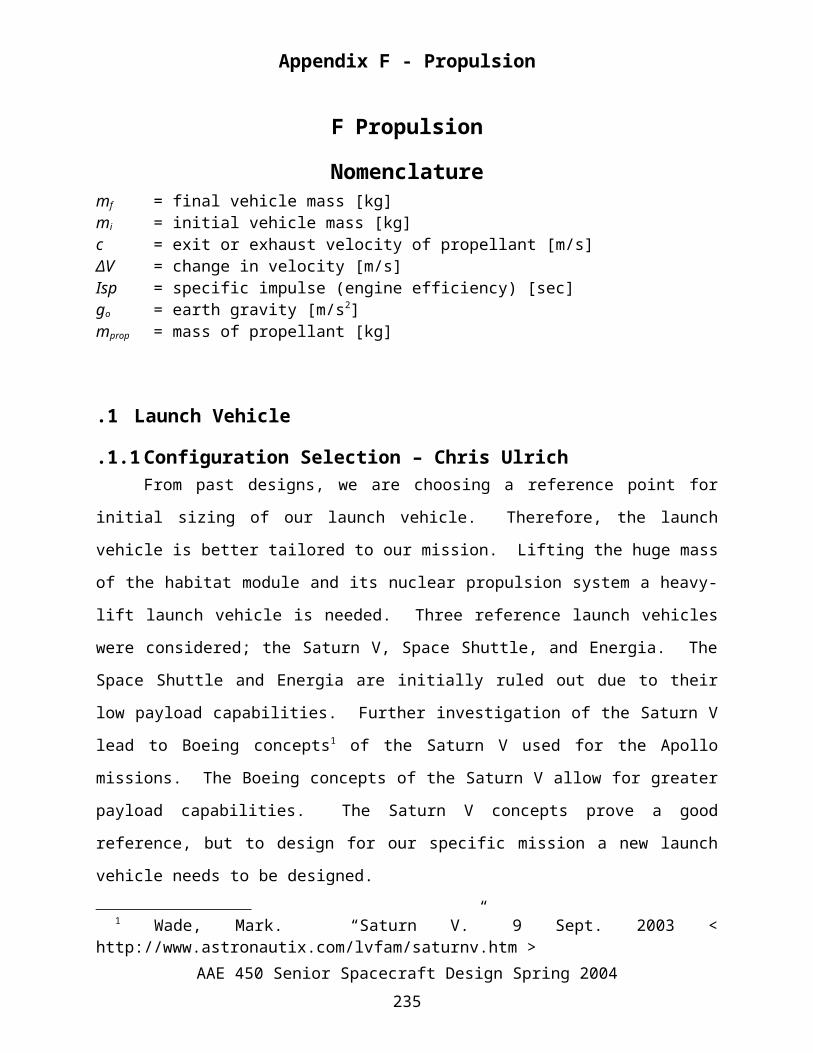
Appendix F - Propulsion F Propulsion Nomenclature m f = final vehicle mass [kg] m i = initial vehicle mass [kg] c = exit or exhaust velocity of propellant [m/s] ΔV = change in velocity [m/s] Isp = specific impulse (engine efficiency) [sec] g o = earth gravity [m/s 2 ] m prop = mass of propellant [kg] .1 Launch Vehicle .1.1 Configuration Selection – Chris Ulrich From past designs, we are choosing a reference point for initial sizing of our launch vehicle. Therefore, the launch vehicle is better tailored to our mission. Lifting the huge mass of the habitat module and its nuclear propulsion system a heavy- lift launch vehicle is needed. Three reference launch vehicles were considered; the Saturn V, Space Shuttle, and Energia. The Space Shuttle and Energia are initially ruled out due to their low payload capabilities. Further investigation of the Saturn V lead to Boeing concepts 1 of the Saturn V used for the Apollo missions. The Boeing concepts of the Saturn V allow for greater payload capabilities. The Saturn V concepts prove a good reference, but to design for our specific mission a new launch vehicle needs to be designed. 1 Wade, Mark. “Saturn V.” 9 Sept. 2003 < http://www.astronautix.com/lvfam/saturnv.htm > AAE 450 Senior Spacecraft Design Spring 2004 235
Transcript of 1 · Web viewInitially, we considered a single stage to orbit launch vehicle. Using the rocket...
Appendix F - Propulsion
F Propulsion
Nomenclature mf = final vehicle mass [kg]mi = initial vehicle mass [kg]c = exit or exhaust velocity of propellant [m/s]ΔV = change in velocity [m/s]Isp = specific impulse (engine efficiency) [sec]go = earth gravity [m/s2]mprop = mass of propellant [kg]
F.1 Launch Vehicle
F.1.1 Configuration Selection – Chris UlrichFrom past designs, we are choosing a reference point for initial sizing of our launch
vehicle. Therefore, the launch vehicle is better tailored to our mission. Lifting the huge mass of
the habitat module and its nuclear propulsion system a heavy-lift launch vehicle is needed.
Three reference launch vehicles were considered; the Saturn V, Space Shuttle, and Energia. The
Space Shuttle and Energia are initially ruled out due to their low payload capabilities. Further
investigation of the Saturn V lead to Boeing concepts1 of the Saturn V used for the Apollo
missions. The Boeing concepts of the Saturn V allow for greater payload capabilities. The
Saturn V concepts prove a good reference, but to design for our specific mission a new launch
vehicle needs to be designed.
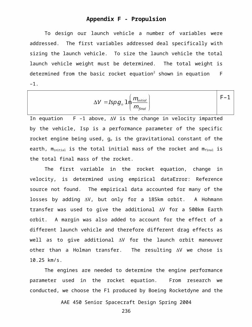
To design our launch vehicle a number of variables were addressed. The first variables
addressed deal specifically with sizing the launch vehicle. To size the launch vehicle the total
launch vehicle weight must be determined. The total weight is determined from the basic rocket
equation2 shown in equation F–1.
F–1
In equation F–1 above, V is the change in velocity imparted by the vehicle, Isp is a
performance parameter of the specific rocket engine being used, go is the gravitational constant
1 Wade, Mark. “Saturn V.” 9 Sept. 2003 < http://www.astronautix.com/lvfam/saturnv.htm >
AAE 450 Senior Spacecraft Design Spring 2004235
Appendix F - Propulsion
of the earth, minitial is the total initial mass of the rocket and mfinal is the total final mass of the
rocket.
The first variable in the rocket equation, change in velocity, is determined using
empirical dataError: Reference source not found. The empirical data accounted for many of the
losses by adding V, but only for a 185km orbit. A Hohmann transfer was used to give the
additional V for a 500km Earth orbit. A margin was also added to account for the effect of a
different launch vehicle and therefore different drag effects as well as to give additional V for
the launch orbit maneuver other than a Holman transfer. The resulting V we chose is 10.25
km/s.
The engines are needed to determine the engine performance parameter used in the rocket
equation. From research we conducted, we choose the F1 produced by Boeing Rocketdyne and
the RD-180 from Pratt & Whitney/ NPO Energomash. Both of these engines are excellent first
stage engines because of their low expansion ratio, high thrust and proven reliability. We are
considering both for the final concept to give good comparison and ensure the best design.
The ratio of the final mass to the initial mass, also considered the mass ratio, is
determined using the intermediate inert mass ratio. Employing the inert mass ratio, we focus on
the mass of the tanks and propulsion system as oppose to including the payload as a factor.
Therefore with the set payload we can focus on clarifying the components of the launch system
specific to propulsion. We defined the inert mass ratio as . The inert mass ratio
was approximated using empirical data of the reference launch vehicles discussed earlier. Inert
mass ratio results in a method of relating the final mass to the total initial mass of the launch
vehicle used for sizing our launch vehicle.
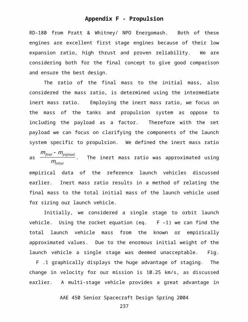
Initially, we considered a single stage to orbit launch vehicle. Using the rocket equation
(eq. F–1) we can find the total launch vehicle mass from the known or empirically approximated
values. Due to the enormous initial weight of the launch vehicle a single stage was deemed
unacceptable. Fig. F.1 graphically displays the huge advantage of staging. The change in
velocity for our mission is 10.25 km/s, as discussed earlier. A multi-stage vehicle provides a
great advantage in gross lift-off weight for a change in velocity of 10.25 km/s. The cost of
weight savings must also be compared to the complexity and safety of the launch vehicle. The
greater risk is simply out weighted, literally, by staging our vehicle. The single stage analysis
AAE 450 Senior Spacecraft Design Spring 2004236
Appendix F - Propulsion
was quickly converted to a two stage vehicle using strap-on boosters for comparison. The two
stage vehicle still resulted in initial launch vehicle masses much greater compared to our
reference designs. Therefore we moved to an even more complex three stage launch vehicle.
0 1000 2000 3000 4000 5000 6000 7000 8000 9000 100000
1
2
3
4
5
6
7
8
9x 10
5
Change in Velocity (m/s)
Gro
ss L
iftof
f wei
ght (
kg)
GLOW vs. V By: Chris UlrichThree-stageTwo-stageOne-stage
Fig. F.1 Gross Liftoff Weight vs. Change in Velocity
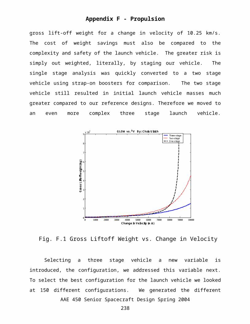
Selecting a three stage vehicle a new variable is introduced, the configuration, we
addressed this variable next. To select the best configuration for the launch vehicle we looked at
150 different configurations. We generated the different configurations from three variables: the
number of boosters, main core engines and third stage engines.
Table F.1 Configuration Number assigned VariablesConfiguration
NumberNumber of Core Engines (1st & 2nd
Stages)
Number of Core Engines
(3rd Stage)
Number of Strap-
on Boosters
Configuration Number
Number of Core Engines (1st & 2nd
Stages)
Number of Core Engines
(3rd Stage)
Number of Strap-
on Boosters
1 2 1 0 76 2 1 3
2 2 2 0 77 2 2 3
3 2 3 0 78 2 3 3
4 2 4 0 79 2 4 3
AAE 450 Senior Spacecraft Design Spring 2004237
Appendix F - Propulsion
5 2 5 0 80 2 5 3
6 3 1 0 81 3 1 3
7 3 2 0 82 3 2 3
8 3 3 0 83 3 3 3
9 3 4 0 84 3 4 3
10 3 5 0 85 3 5 3
11 4 1 0 86 4 1 3
12 4 2 0 87 4 2 3
13 4 3 0 88 4 3 3
14 4 4 0 89 4 4 3
15 4 5 0 90 4 5 3
16 5 1 0 91 5 1 3
17 5 2 0 92 5 2 3
18 5 3 0 93 5 3 3
19 5 4 0 94 5 4 3
20 5 5 0 95 5 5 3
21 6 1 0 96 6 1 3
22 6 2 0 97 6 2 3
23 6 3 0 98 6 3 3
24 6 4 0 99 6 4 3
25 6 5 0 100 6 5 3
26 2 1 1 101 2 1 4
27 2 2 1 102 2 2 4
28 2 3 1 103 2 3 4
29 2 4 1 104 2 4 4
30 2 5 1 105 2 5 4
31 3 1 1 106 3 1 4
32 3 2 1 107 3 2 4
33 3 3 1 108 3 3 4
34 3 4 1 109 3 4 4
35 3 5 1 110 3 5 4
36 4 1 1 111 4 1 4
37 4 2 1 112 4 2 4
38 4 3 1 113 4 3 4
39 4 4 1 114 4 4 4
40 4 5 1 115 4 5 4
41 5 1 1 116 5 1 4
AAE 450 Senior Spacecraft Design Spring 2004238
Appendix F - Propulsion
42 5 2 1 117 5 2 4
43 5 3 1 118 5 3 4
44 5 4 1 119 5 4 4
45 5 5 1 120 5 5 4
46 6 1 1 121 6 1 4
47 6 2 1 122 6 2 4
48 6 3 1 123 6 3 4
49 6 4 1 124 6 4 4
50 6 5 1 125 6 5 4
51 2 1 2 126 2 1 5
52 2 2 2 127 2 2 5
53 2 3 2 128 2 3 5
54 2 4 2 129 2 4 5
55 2 5 2 130 2 5 5
56 3 1 2 131 3 1 5
57 3 2 2 132 3 2 5
58 3 3 2 133 3 3 5
59 3 4 2 134 3 4 5
60 3 5 2 135 3 5 5
61 4 1 2 136 4 1 5
62 4 2 2 137 4 2 5
63 4 3 2 138 4 3 5
64 4 4 2 139 4 4 5
65 4 5 2 140 4 5 5
66 5 1 2 141 5 1 5
67 5 2 2 142 5 2 5
68 5 3 2 143 5 3 5
69 5 4 2 144 5 4 5
70 5 5 2 145 5 5 5
71 6 1 2 146 6 1 5
72 6 2 2 147 6 2 5
73 6 3 2 148 6 3 5
74 6 4 2 149 6 4 5
75 6 5 2 150 6 5 5
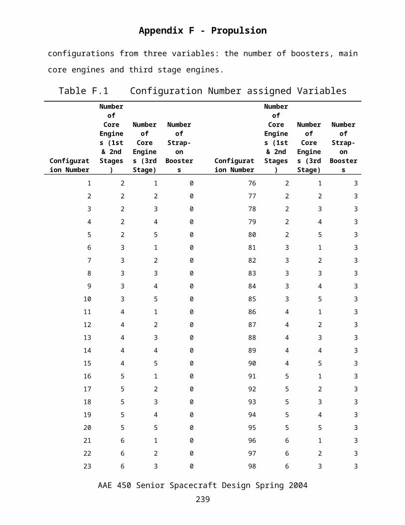
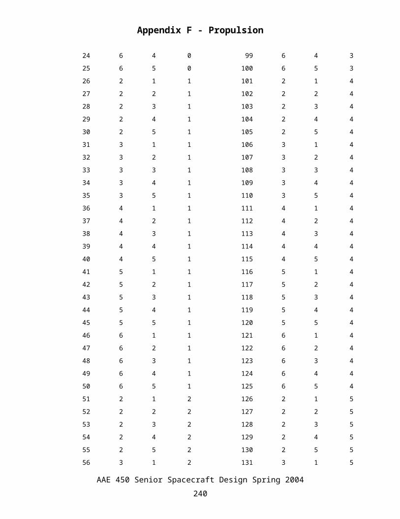
Table F.1 shows the variables assigned to each configuration, this will be important later in
viewing the results. The general MATLAB code configurationOPTIMISATION.m, was made to
AAE 450 Senior Spacecraft Design Spring 2004239
Appendix F - Propulsion
evaluate each configuration and display the results graphically. Each configuration was
evaluated using the function PROP_3stageLV_arrayDV3.m. The function
PROP_3stageLV_arrayDV3.m is a simple function using the basic rocket equation (shown
below as equationF–1) and methods developed with the guidance of Dr. W. Anderson. The
complication of the function was created by generalizing the function to evaluate any type of
configuration; disregarding how unrealistic the configuration is. Unrealistic configurations can
arise from thrust-to-weights less than one, etc. PROP_3stageLV_arrayDV3.m uses input values
specific to the type of rocket engine and strap-on boosters to determine the major launch vehicle
parameters. The launch vehicle engine parameters are in a layout at the top of the function to
allow a quick change of engine parameters to compare results. An array of third stage V
fractions is used to compare yet another variable in determining the total launch vehicle mass.
The third stage fraction is the percentage of the total V imparted by the third stage. The input
engine parameters are used to first compute the mass of the third stage from equation F–1 above.
The mass is then determined for the array of third stage fractions. Now the mass guessing game
begins. To determine the total mass and the mass of the second stage an initial guess is used to
check the amount of V imparted by the first two stages. The mass for each stage cannot be
found separately because boosters guarantee a specified burn time. This burn time coupled with
the initial mass guess will deliver a certain amount of change in velocity (V). The initial mass
of the second stage can then be found using the mass flow rate of the first stage main core
engines and the specified burn time of the boosters. Therefore with an initial guess of the total
launch vehicle mass the change in velocity can be found for each stage. Adding up the V for
each stage, the total V is calculated. If there is not a total launch mass found from the array
guess within 1% of the desired total V, the mass would be too high for consideration and
therefore the output is defined as an error. The error is shown by negative propellant masses
which can be easily seen in a plot of the launch vehicle propellant masses. Once a total launch
vehicle mass is found all of the other output parameters can be found from simple calculations.
The major output considered in the configuration process was the total launch vehicle
mass. The lowest launch vehicle mass directly relates to a lower launch vehicle cost, therefore
this was deemed the primary variable to investigate. The total launch vehicle mass was limited
with an upper bound set by a minimum thrust-to-weight of 1.1. The lower bound was
determined from erroneous results from the function code PROP_3stageLV_arrayDV3.m. Fig.
AAE 450 Senior Spacecraft Design Spring 2004240
Appendix F - Propulsion
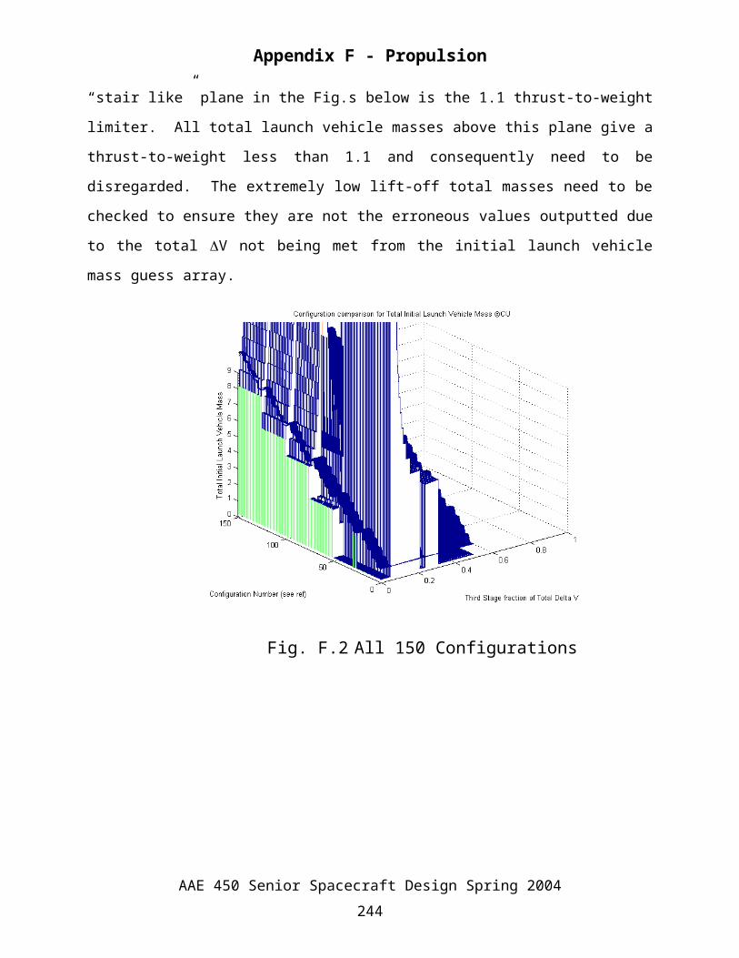
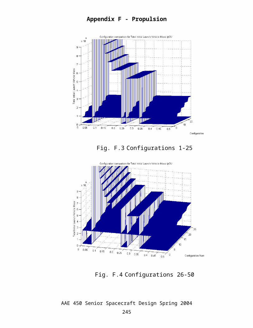
F.2- Fig. F.9 below are examples of the output graphs from the 150 configurations considered.
The output graphs show the total launch vehicle mass for each configuration for an array of
change in velocity (V) fractions. The third stage V fractions range from 0-0.5 or 0-50% of the
total change in velocity required for the launch vehicle. Fig. F.2 all 150 configurations are
compared together, this gives a good look at general magnitudes for the configurations. To give
a more detailed look at the total launch vehicle mass 25 configurations were compared together.
The 25 configuration grouping compares a set number of strap-on boosters to all the possible
engine configurations for the main core and the third stage. Table F.1 shows this relationship.
The “stair like” plane in the Fig.s below is the 1.1 thrust-to-weight limiter. All total launch
vehicle masses above this plane give a thrust-to-weight less than 1.1 and consequently need to be
disregarded. The extremely low lift-off total masses need to be checked to ensure they are not
the erroneous values outputted due to the total V not being met from the initial launch vehicle
mass guess array.
Fig. F.2 All 150 Configurations
AAE 450 Senior Spacecraft Design Spring 2004241
Appendix F - Propulsion
Fig. F.3 Configurations 1-25
Fig. F.4 Configurations 26-50
AAE 450 Senior Spacecraft Design Spring 2004242
Appendix F - Propulsion
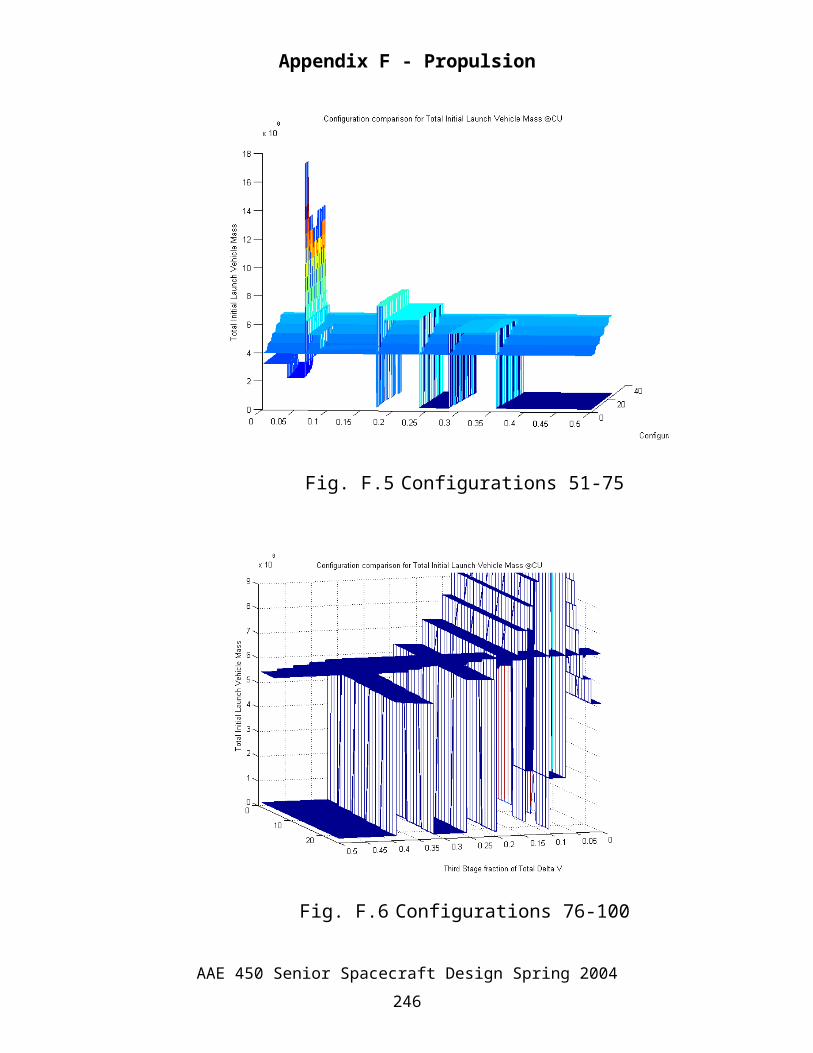
Fig. F.5 Configurations 51-75
Fig. F.6 Configurations 76-100
AAE 450 Senior Spacecraft Design Spring 2004243
Appendix F - Propulsion
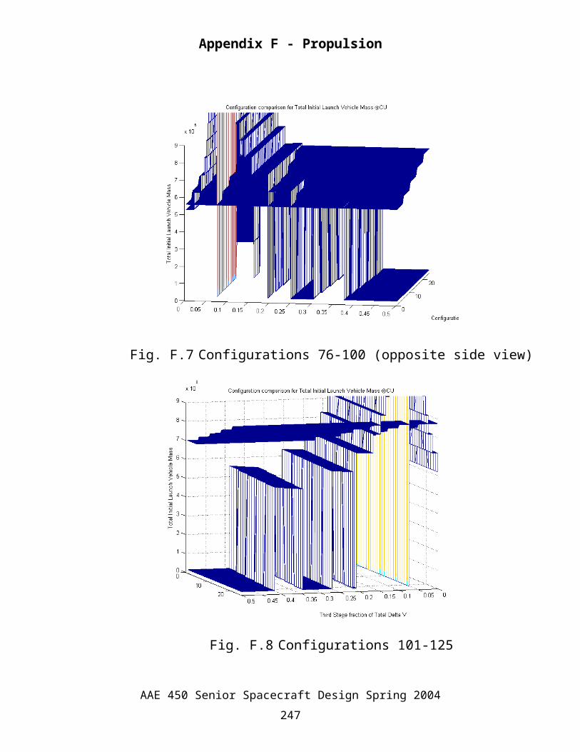
Fig. F.7 Configurations 76-100 (opposite side view)
Fig. F.8 Configurations 101-125
AAE 450 Senior Spacecraft Design Spring 2004244
Appendix F - Propulsion
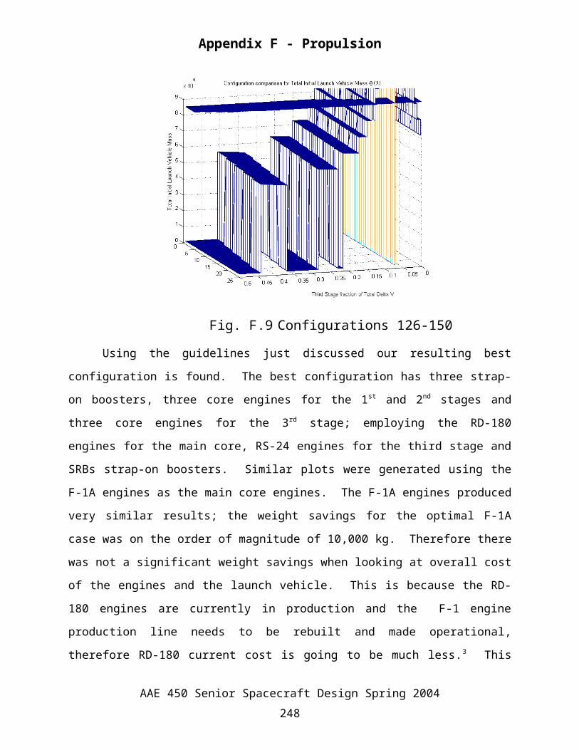
Fig. F.9 Configurations 126-150
Using the guidelines just discussed our resulting best configuration is found. The best
configuration has three strap-on boosters, three core engines for the 1st and 2nd stages and three
core engines for the 3rd stage; employing the RD-180 engines for the main core, RS-24 engines
for the third stage and SRBs strap-on boosters. Similar plots were generated using the F-1A
engines as the main core engines. The F-1A engines produced very similar results; the weight
savings for the optimal F-1A case was on the order of magnitude of 10,000 kg. Therefore there
was not a significant weight savings when looking at overall cost of the engines and the launch
vehicle. This is because the RD-180 engines are currently in production and the F-1 engine
production line needs to be rebuilt and made operational, therefore RD-180 current cost is going
to be much less.3 This was the sole factor in choosing the RD-180 for our current design, bottom
line cost.
%configurationOPTIMIZATION.m%%AAE 450 - Spring 2004%Author: Chris Ulrich and Nik Ladisch%Date Created: 2/20/04%Last Modified: 3/28/04%%**********************************************************************%DESCRIPTION
AAE 450 Senior Spacecraft Design Spring 2004245
Appendix F - Propulsion
%Uses differrent configurations to compare different launch vehicle%parameters%%METHODS OF CALCULATION%All real calculations are done in the function PROP_3stageLV_arrayDV3.m%this code just uses the created function to input different%configurations and then graphically compare the output parameters%%CALLED FUNCTIONS%PROP_3stageLV_arrayDV3.m%%VARIABLES%listed below%%**********************************************************************
clear allclose allclc
%FOR loops created by NIK (if you could not tell by the cool naming%convention) to input different configurationsconfig=1;for niks3=0:5%number of boosters the 1st stage (boost)for niks1=2:6%number of core engines for 1st and 2nd stage (core_1_2) for niks2=1:5%number of core engines for 3rd stage (core_3) [Total_LV(config,:),third_stage_fraction(config,:),MOc_1(config,:),mf_core1(config,:),mp_core1(config,:),mo_boost(config,:),mo2(config,:),mf_2(config,:),mp_core2(config,:),core_3(config,:),mo3(config,:),mf_3(config,:),mp3(config,:),DV1(config,:),DV2(config,:),TW_initial(config,:),TW_max_1st(config,:),TW_max_2nd(config,:),TW_max_3rd(config,:)]=PROP_3stageLV_arrayDV3_rd180(niks1,niks2,niks3); config=config+1; end endend
sizer = size(config)numberofCONFIGS = [1:150];count = 1for niks3=0:5%number of boosters the 1st stage (boost) for niks1=2:6%number of core engines for 1st and 2nd stage (core_1_2) for niks2=1:5%number of core engines for 3rd stage (core_3) thrust_core1_2 = niks1*3.826000e6 ;%[N] Thrust of theRD-180 engine at Sea level thrust_core3 = niks2*2278e3;%[N] Vaccum SSME thrust_boosters = niks3*1.379e7;%[N] Thrust of the RSRM booster at SEA LEVEL %Finiding the total thrust of the configuration at lift off to %set the limiting weight of the launch vehicle to equal to %TW of 1.1 TW_limiter(count) = (thrust_core1_2+thrust_boosters).*(1.1/9.81);%kg count = count + 1; end
AAE 450 Senior Spacecraft Design Spring 2004246
Appendix F - Propulsion
endendnumberCONFIG = [1:150]; fraction_3rdSTAGE_DV = linspace(0.001,0.5,1e4);TW_trans = TW_limiter';
Part_1 = [Total_LV(1,:)];TW_limiter1 = [linspace(TW_trans(1,1)-0.000001,TW_trans(1,1)+0.000001,1e4)];number_1 = [1:25];for q = 2:25 Part_1 = [Part_1;Total_LV(q,:)]; expander1 = linspace(TW_trans(q,1)-0.000001,TW_trans(q,1)+0.000001,1e4); TW_limiter1 = [TW_limiter1;expander1];end
Part_2 = [Total_LV(26,:)];TW_limiter2 = [linspace(TW_trans(26,1)-0.000001,TW_trans(26,1)+0.000001,1e4)];number_2 = [26:50];for q = 27:50 Part_2 = [Part_2;Total_LV(q,:)]; expander2 = linspace(TW_trans(q,1)-0.000001,TW_trans(q,1)+0.000001,1e4); TW_limiter2 = [TW_limiter2;expander2];end
Part_3 = [Total_LV(51,:)];TW_limiter3 = [linspace(TW_trans(51,1)-0.000001,TW_trans(51,1)+0.000001,1e4)];number_3 = [51:75];for q = 52:75 Part_3 = [Part_3;Total_LV(q,:)]; expander3 = linspace(TW_trans(q,1)-0.000001,TW_trans(q,1)+0.000001,1e4); TW_limiter3 = [TW_limiter3;expander3];end
Part_4 = [Total_LV(76,:)];TW_limiter4 = [linspace(TW_trans(76,1)-0.000001,TW_trans(76,1)+0.000001,1e4)];number_4 = [76:100];for q = 77:100 Part_4 = [Part_4;Total_LV(q,:)]; expander4 = linspace(TW_trans(q,1)-0.000001,TW_trans(q,1)+0.000001,1e4); TW_limiter4 = [TW_limiter4;expander4]end
Part_5 = [Total_LV(101,:)];TW_limiter5 = [linspace(TW_trans(101,1)-0.000001,TW_trans(101,1)+0.000001,1e4)];number_5 = [101:125];for q = 102:125 Part_5 = [Part_5;Total_LV(q,:)]; expander5 = linspace(TW_trans(q,1)-0.000001,TW_trans(q,1)+0.000001,1e4); TW_limiter5 = [TW_limiter5;expander5];end
Part_6 = [Total_LV(126,:)];TW_limiter6 = [linspace(TW_trans(126,1)-0.000001,TW_trans(126,1)+0.000001,1e4)];number_6 = [126:150];for q = 127:150
AAE 450 Senior Spacecraft Design Spring 2004247
Appendix F - Propulsion
Part_6 = [Part_6;Total_LV(q,:)]; expander6 = linspace(TW_trans(q,1)-0.000001,TW_trans(q,1)+0.000001,1e4); TW_limiter6 = [TW_limiter6;expander6];end
% Fig.(1)% hold on;% waterfall(fraction_3rdSTAGE_DV,numberCONFIG,Total_LV);% xlabel('Third Stage fraction of Total Delta V');% ylabel('Configuration Number (see ref)');% zlabel('Total Initial Launch Vehicle Mass');% title('Configuration comparison for Total Initial Launch Vehicle Mass \copyrightCU');% AXIS([0 1 0 150 0 9e6])% mesh(fraction_3rdSTAGE_DV,number_1,TW_limiter1);% mesh(fraction_3rdSTAGE_DV,number_2,TW_limiter2);% mesh(fraction_3rdSTAGE_DV,number_3,TW_limiter3);% mesh(fraction_3rdSTAGE_DV,number_4,TW_limiter4);% mesh(fraction_3rdSTAGE_DV,number_5,TW_limiter5);% mesh(fraction_3rdSTAGE_DV,number_6,TW_limiter6);% % hold off;% % Fig.(2)% hold on% mesh(fraction_3rdSTAGE_DV,number_1,Part_1);% xlabel('Third Stage fraction of Total Delta V');% ylabel('Configuration Number 1-25 [see ref.]');% zlabel('Total Initial Launch Vehicle Mass');% title('Configuration comparison for Total Initial Launch Vehicle Mass \copyrightCU');% mesh(fraction_3rdSTAGE_DV,number_1,TW_limiter1);% hold off% % Fig.(3)% hold on% mesh(fraction_3rdSTAGE_DV,number_1,Part_2);% xlabel('Third Stage fraction of Total Delta V');% ylabel('Configuration Number 26-50 [see ref.]');% zlabel('Total Initial Launch Vehicle Mass');% title('Configuration comparison for Total Initial Launch Vehicle Mass \copyrightCU');% mesh(fraction_3rdSTAGE_DV,number_1,TW_limiter2);% hold off% % Fig.(4)% hold on% mesh(fraction_3rdSTAGE_DV,number_1,Part_3);% xlabel('Third Stage fraction of Total Delta V');% ylabel('Configuration Number 51-75 [see ref.]');% zlabel('Total Initial Launch Vehicle Mass');% title('Configuration comparison for Total Initial Launch Vehicle Mass \copyrightCU');% mesh(fraction_3rdSTAGE_DV,number_1,TW_limiter3);% hold off%
AAE 450 Senior Spacecraft Design Spring 2004248
Appendix F - Propulsion
% Fig.(5)% hold on% mesh(fraction_3rdSTAGE_DV,number_1,Part_4);% xlabel('Third Stage fraction of Total Delta V');% ylabel('Configuration Number 76-100 [see ref.]');% zlabel('Total Initial Launch Vehicle Mass');% title('Configuration comparison for Total Initial Launch Vehicle Mass \copyrightCU');% mesh(fraction_3rdSTAGE_DV,number_1,TW_limiter4);% AXIS([0 0.5 0 25 0 9e6])% hold off% % Fig.(6)% hold on% mesh(fraction_3rdSTAGE_DV,number_1,Part_5);% xlabel('Third Stage fraction of Total Delta V');% ylabel('Configuration Number 101-125 [see ref.]');% zlabel('Total Initial Launch Vehicle Mass');% title('Configuration comparison for Total Initial Launch Vehicle Mass \copyrightCU');% mesh(fraction_3rdSTAGE_DV,number_1,TW_limiter5);% AXIS([0 0.5 0 25 0 9e6])% hold off% Fig.(7)hold onmesh(fraction_3rdSTAGE_DV,number_1,Part_6);xlabel('Third Stage fraction of Total Delta V');ylabel('Configuration Number 126-150 [see ref.]');zlabel('Total Initial Launch Vehicle Mass');title('Configuration comparison for Total Initial Launch Vehicle Mass \copyrightCU');mesh(fraction_3rdSTAGE_DV,number_1,TW_limiter6);AXIS([0 0.5 0 25 0 9e6])hold offgrid
function [Total_LV,third_stage_fraction,MOc_1,mf_core1,mp_core1,mo_boost,mo2,mf_2,mp_core2,core_3,mo3,mf_3,mp3,DV1,DV2,TW_initial,TW_max_1st,TW_max_2nd,TW_max_3rd,TOTAL_CORE_LENGTH]=PROP_3stageLV_arrayDV3(core_1_2,core_3,boost)
% MASSES = [Total_LV,core_1,MOc_1,mf_core1,mp_core1,...% strapON,mo_boost,core_1,mo2,mf_2,mp_core2,core_3,mo3,mf_3,mp3];% THRUST_WEIGHT = [TW_initial,TW_max_1st,TW_max_2nd,TW_max_3rd];% DVS_STAGES =[DV1,DV2,DV/2,DVcheck];
%PROP_initial_size_LVF.m%%AAE 450 - Spring 2004%Author: Chris Ulrich%Date Created: 1/22/04%Last Modified: 3/25/04%%**************************************************************************%DESCRIPTION%Calculates propellant & core sturcture needed for the core engines
AAE 450 Senior Spacecraft Design Spring 2004249
Appendix F - Propulsion
%%METHODS OF CALCULATION%rocket equation for simple ideal rocket %%CALLED FUNCTIONS%none%%VARIABLES%listed below%%**************************************************************************
% clear all% close all% clc
% core_1_2 =3;% core_3=3;% boost=3;%TO REDUCE RUN TIME REDUCE SIZE OF LINSPACE VARIABLEpoint_initialguess = 1e4;%number of points for intial mass guess
%For staged rocket the total change in velocity is just the sum of each%stages delta v addition
%%%%%%%%%%%%%%%%%%%%%%%%%%%%%%%%%%%%%%%%%%%%%%%%%%%%%%%%%%%%%%%%%%%%%%%%%%%% Parameters%%%%%%%%%%%%%%%%%%%%%%%%%%%%%%%%%%%%%%%%%%%%%%%%%%%%%%%%%%%%%%%%%%%%%%%%%%%%DELTA V REQUIRED DV = 10.5e3;%11179;%[m/s] go = 9.81;%[m/s^2] (gravitational constant) %DELTA V split-upthird_stage_fraction = linspace(0.001,0.5,point_initialguess);first_two = 1-third_stage_fraction;
%PAYLOAD mpay = 200000;%[kg]%%1st Stage%%%%%%%%%%%%%%%%%%%%%%%%%% STRAP-ON BOOSTER %%%%%%%%%%%%%%%%%%%%%%%%%%%%%%%%%RSRM (Space Shuttle Boosters)strapON = 'RSRM';number_boosters = boost;Isp_booster = 268.2;%[s] (RSRM alt.)F_booster = 1.379e7;%[N] Thrust of the booster at SEA LEVELmf_1boost = 67703;%[kg] Mass final for one booster (no propellant/empty booster case) mp_1boost = 501629;%[kg] Mass prop for one booster % mo_1boost = 569332;%[kg]tb_boost = 123.7;%[s]
%TITAN UA1205 (Used on Saturn V derivative Saturn MLV5-4SB% strapON = 'TITAN UA1205';% number_boosters = 10;
AAE 450 Senior Spacecraft Design Spring 2004250
Appendix F - Propulsion
% Isp_booster = 238;%[s] (RSRM alt.)% F_booster = 900e3;%[N] Thrust of the booster% % mdot_boost = 4055.21;%[kg/s] (average) % mf_boost = 33798 ;%[kg]% mo_boost = 226233 ;%[kg] % mp_1boost = mo_boost-mf_boost;%[kg] Mass prop for one booster% tb_boost = 115;%[s]
%%%%%%%%%%%%%%%%%%%%%%%%% CORE ENGINES %%%%%%%%%%%%%%%%%%%%%%%%%%%%%%%%%%%core_1 = 'RD 180';%F-1A ENGINE PARAMETERSnumber_coreENGINES = core_1_2;Isp_core = 311;%[s] (RD-180 SL)F_core = 3.826000e6 ;%[N] Thrust of the engine at Sea levelMR_core = 0.04;%Mass Ratio of the core (MR = mfinal/minitial) ******************************************************************TweekOF_core = 2.72;diameterCORE = 10;%[m]densityCORE_f = 1141;%[kg/m^3] RP-1/KerosenedensityCORE_ox = 810;%[kg/m^3] Liquid Oxygen
% core_1 = 'F-1A';% %F-1A ENGINE PARAMETERS% number_coreENGINES = core_1_2;% Isp_core = 290;%[s] average SL and VACCUM {270;%[s] (F-1A SL)}********************************************** AVERAGE SL and VACCUM% F_core = 9189.60e3 ;%[N] Thrust of the engine at Sea level% MR_core = 0.0626;%Mass Ratio of the core (MR = mfinal/minitial) % OF_core = 2.27;% diameterCORE = 10;%[m]% densityCORE_f = 1141;%[kg/m^3] RP-1/Kerosene% densityCORE_ox = 810;%[kg/m^3] Liquid Oxygen
% % core_1 = 'F-1';%F-1 ENGINE PARAMETERS% % number_coreENGINES = 4;% % Isp_core = 265;%[s] (F-1 SL)% % F_core = 7.74050e6;%[kN] Thrust of engine in Vaccum% % mf_core = 135218;%[kg]% % MR_core = 0.0626;%Mass Ratio of the core (MR = mfinal/minitial)% % OF_core = 2.27;% % diameterCORE = 6.3;%[m]% % densityCORE_f = 810;%[kg/m^3]% % densityCORE_ox = 1141;%[kg/m^3] Liquid Oxygen
%%%%%%%%%%%%%%%%%%%%%%%%%%%%%%%%%%%%%%%%%%%%%%%%%%%%%%%%%%%%%%%%%%%%%%%%%%%% 3rd STAGE%%%%%%%%%%%%%%%%%%%%%%%%%%%%%%%%%%%%%%%%%%%%%%%%%%%%%%%%%%%%%%%%%%%%%%%%%%%core3 = 'SSME';%RS-24 SSME ENGINE PARAMETERSnumber_coreENGINES3 = core_3;Isp_3 = 453;%[s] VACCUM F_core3 = 2278e3;%[N] VaccumMR_3 = 0.11;%Mass Ratio of the core (MR = mfinal/minitial)
AAE 450 Senior Spacecraft Design Spring 2004251
Appendix F - Propulsion
OF_core3 = 6.00;% diameterCORE = 6.3;%[m]densityCORE_f3 = 71;%[kg/m^3] H2densityCORE_ox3 = 1141;%[kg/m^3] Liquid Oxygen% Mass Engine: 3,177 kg. % Diameter: 1.63 m. Thrust to Weight Ratio: 73.12.
% core3 = 'Nuclear';% %Nuclear ENGINE PARAMETERS (same nuc as on spacecraft)% number_coreENGINES3 = core_3;% Isp_3 = 1300;%[s] VACCUM % F_core3 = 20e3;%[N] Vaccum% MR_3 = 0.5;%Mass Ratio of the core (MR = mfinal/minitial) % OF_core3 = 1;% % diameterCORE = 6.3;%[m]% densityCORE_f3 = 1;%% densityCORE_ox3 = 1;%% % Mass Engine: kg. % % Diameter: m. Thrust to Weight Ratio:
%%%%%%%%%%%%%%%%%%%%%%%%%%%%%%%%%%%%%%%%%%%%%%%%%%%%%%%%%%%%%%%%%%%%%%%%%%%% Rocket Equation %%%%%%%%%%%%%%%%%%%%%%%%%%%%%%%%%%%%%%%%%%%%%%%%%%%%%%%%%%%%%%%%%%%%%%%%%%%%The Rocket equation was used neglecting drag and gravity (These two %parameters can be accounted for by increasing the delta V). All the%known parameters were used to isolate the unknown intial mass which was %then iteritativly solved for
%3rd STAGE initial mass:mo3 = mpay.*(1-exp(DV.*third_stage_fraction./(Isp_3*go)))./... (MR_3.*exp(DV.*third_stage_fraction./(Isp_3.*go))-1); %This mass is simply added to the payload mass that the first two %stages lift into orbit. The third stage intial mass is found from %using the rocket eqution for a fixed portion of the total delta v %needed for 500 km orbit. This parameter is set up to be varied for %an array of values for any fixed configuration (i.e. 2 boosters, 4 core %engines 1st and 2nd stage, 3 core engines 3rd stage)
%1st stage average IspIsp_1 = (Isp_booster*number_boosters+Isp_core*number_coreENGINES)... /(number_coreENGINES+number_boosters);%average Isp of 1st stage%Initial total Booster values mp_boost = mp_1boost*number_boosters;%mass prop. for boosters mo_boost = mp_boost + mf_1boost*number_boosters; mf_boost = mf_1boost*number_boosters;%kg%Mass flow of the core enginemdot_core = F_core/(Isp_core*go);%[kg/s] ==> mdot = F/Isp.go
%New Payload with upper stage (the payload for the 1st and 2nd stages is%just that of the dry payload and the 3rd stage propulsion components)mpay1 = mo3;
AAE 450 Senior Spacecraft Design Spring 2004252
Appendix F - Propulsion
%INITIAL GUESS OF INITIAL CORE MASSmo_core1 = 2e6;%kg%CHECK to see how much fuel will burn in time of boosters %this check is done to make sure the mass is not less than that of the %burned in the time of the boosters %ALSO CHECK to make sure boosters are used if boost~=0 BURNED_FUEL_1stSTAGE = mdot_core*tb_boost*number_coreENGINES; if BURNED_FUEL_1stSTAGE > mo_core1 mo_core1 = BURNED_FUEL_1stSTAGE + MR_core*BURNED_FUEL_1stSTAGE + 1e6; end end%DELTA V GUESS RANGE %uses intial guess as minium (min. is set by burn time of the booster)%max is arbitrary value adjusted from the miniummo_core_MAXguess = 1e10;
DV_want = first_two.*DV;%Total Delta V of LV for 1st and 2nd stages
% point_initialguess = 1e4;%number of points for intial mass guessmo_core = linspace(mo_core1,mo_core_MAXguess,point_initialguess);%To find the inital mass of the core for each different delta v split-up a%for loop is used to: run each DV split-up for guesses of intial massDVarraysize = size(third_stage_fraction);DV1 = ones(DVarraysize(1,1), point_initialguess);for i = 1:DVarraysize(1,2); mo2_frommdot = mo_core-mdot_core.*tb_boost.*number_coreENGINES; DV1 = Isp_1.*go.*log((mo_core+mo_boost+mpay1(i))./(mo2_frommdot+mf_boost+mpay1(i))); DV2 = Isp_core.*go.*log((mo2_frommdot+mpay1(i))./(MR_core.*mo_core+mpay1(i))); Total_DELTAV = DV1+DV2; spot = find(Total_DELTAV(1,:) > DV_want(i)*.999 & Total_DELTAV(1,:) < DV_want(i)*1.005); spott = find(Total_DELTAV(1,:) > DV_want(i)*.99 & Total_DELTAV(1,:) < DV_want(i)*1.01); %spot finds the correct delta v need to achieve the desired orbit, from %this delta v the initial mass of the fist stage can be found in the guess %array if spot ~= 0 DV_1_2(i) = Total_DELTAV(spot(1)); MOc_1(i) = mo_core(spot(1))+mpay1(i); elseif spott ~= 0 DV_1_2(i) = Total_DELTAV(spott(1)); MOc_1(i) = mo_core(spott(1))+mpay1(i); else DV_1_2(i) = 0; MOc_1(i) = 0; mo3(i) = 0; mo_boost = 0; mpay1(i) = 0; endend
%Below is just a check of the delta v values to ensure that the desired
AAE 450 Senior Spacecraft Design Spring 2004253
Appendix F - Propulsion
%delta v is found. mo2_frommdot = MOc_1-mdot_core.*tb_boost.*number_coreENGINES;DV1 = Isp_1.*go.*log((MOc_1+mo_boost)./(mo2_frommdot+mf_boost));DV2 = Isp_core.*go.*log((mo2_frommdot)./(MR_core.*(MOc_1-mpay1)+mpay1));DV3 = DV.*third_stage_fraction;DVcheck = DV1+DV2+DV3;
%TOTAL mass of the launch vehicleTotal_LV = MOc_1 + mo_boost + mpay;
%1st STAGE CORE %Final mass of core FIRST stage with final mass of boosters mf_core1 = MOc_1-mdot_core*tb_boost*number_coreENGINES+mf_boost; %Propellant mass of core FIRST stage mp_core1 = mdot_core*tb_boost*number_coreENGINES;%2nd STAGE CORE %Initial mass of core SECOND stage (after boosters) mo2 = MOc_1-mdot_core*tb_boost*number_coreENGINES; %Final mass of the core SECOND stage mf_2 = MR_core.*MOc_1+mpay1; %Propellant mass of core SECOND stage mp_core2 = MOc_1-mf_2;%3rd STAGE CORE %Initial mass of core THIRD stage mo3 = mo3; %Final Mass of core stage mf_3 = mo3.*MR_3+mpay; %Propellant mass of core stage mp3 = mo3-mf_3;
%Thrust to WeightTotal_thrust_1st = number_coreENGINES*F_core + number_boosters*F_booster;Total_thrust_2nd = number_coreENGINES*F_core;% shouldbeONEONE = size(number_coreENGINES3) number_coreENGINES3(shouldbeONEONE(1))*F_core3;Total_thrust_3rd = number_coreENGINES3*F_core3;MIN_weight_1st = (mo2+mf_boost).*9.81;if MIN_weight_1st <=0; MIN_weight_1st = 1;endMIN_weight_2nd = (mf_2 ).*9.81;if MIN_weight_2nd <=0; MIN_weight_2nd = 1;endMIN_weight_3rd = (mf_3 ).*9.81;if MIN_weight_3rd <=0; MIN_weight_3rd = 1;endTW_initial = Total_thrust_1st./(Total_LV.*9.81);TW_max_1st = Total_thrust_1st./MIN_weight_1st;TW_max_2nd = Total_thrust_2nd./MIN_weight_2nd;TW_max_3rd = Total_thrust_3rd./MIN_weight_3rd;
%TANK VOLUME AND SIZING%CORE FIRST & SECOND STAGESfraction_f = 1/(1+OF_core);
AAE 450 Senior Spacecraft Design Spring 2004254
Appendix F - Propulsion
fraction_ox = 1 - fraction_f;volumeCORE_f1 = (mp_core1+mp_core2).*fraction_f./densityCORE_f;voumeCORE_ox1 = (mp_core1+mp_core2).*fraction_ox./densityCORE_ox;volumeCORE1 = voumeCORE_ox1 + volumeCORE_f1;lengthCORE1 = volumeCORE1./(pi*diameterCORE^2/4);%CORE THIRD STAGEfraction_f3 = 1/(1+OF_core);fraction_ox3 = 1 - fraction_f3;volumeCORE_f3 = mp3.*fraction_f3./densityCORE_f3;voumeCORE_ox3 = mp3.*fraction_ox3./densityCORE_ox3;volumeCORE3 = voumeCORE_ox3 + volumeCORE_f3;lengthCORE3 = volumeCORE3./(pi*diameterCORE^2/4);TOTAL_CORE_LENGTH = lengthCORE1 + lengthCORE3;
% % % % Fig.(1)% % plot(third_stage_fraction,Total_LV)% % xlabel('DV fraction produced by the Third Stage')% % ylabel('Total Launch Vehicle Mass (kg)')% % title('Total LV mass Vs. 3^r^d Stage DV fraction')% % Fig.(2)% % plot(third_stage_fraction,Total_LV)% % xlabel('DV fraction produced by the Third Stage')% % ylabel('Total Launch Vehicle Mass (kg)')% % title('Total LV mass Vs. 3^r^d Stage DV fraction')% % AXIS([third_stage_fraction(1) third_stage_fraction(i) 0 9e6])% %
% % % % home% % fprintf('\t\t\t\t\tRESULTS\n')% % fprintf('\t\tMASSES OF LAUNCH VEHICLE\n')% % fprintf('TOTAL MASS of launch vehicle (kg):\t%6.2e\n',Total_LV)% % % % fprintf('\t1st STAGE\n')% % fprintf('\tCORE BOOSTER (%4s)\n',core_1)% % fprintf('\tInitial Mass Core Booster (kg):\t%6.2e\n',MOc_1)% % fprintf('\tFinal Mass Core Booster (kg):\t%6.2e\n',mf_core1)% % fprintf('\tPropellant Mass Core Booster (kg):\t%6.2e\n',mp_core1)% % fprintf('\tSTRAP-ON BOOSTER (%5s)\n',strapON)% % fprintf('\tInitial Mass Strap-on Booster (kg):\t%6.2e\n',mo_boost)% % % % % % fprintf('\t2nd STAGE\n')% % fprintf('\tCORE BOOSTER (%4s)\n',core_1)% % fprintf('\tInitial Mass Core Booster (kg):\t%6.2e\n',mo2)% % fprintf('\tFinal Mass Core Booster (kg):\t%6.2e\n',mf_2)% % fprintf('\tPropellant Mass Core Booster (kg):\t%6.2e\n',mp_core2)% % % % fprintf('\t3rd STAGE (%4s)\n',core3)% % fprintf('\tInitial Mass Core Booster (kg):\t%6.2e\n',mo3)% % fprintf('\tFinal Mass Core Booster (kg):\t%6.2e\n',mf_3)% % fprintf('\tPropellant Mass Core Booster (kg):\t%6.2e\n',mp3)
AAE 450 Senior Spacecraft Design Spring 2004255
Appendix F - Propulsion
% % % % fprintf('\tTHRUST to WEIGHT of LAUNCH VEHICLE\n')% % fprintf('\t Initial Thrust to Weight at Lift-off:\t%6.2f\n',TW_initial)% % fprintf('\t Max Thrust to Weight of 1st Stage:\t%6.2f\n',TW_max_1st)% % fprintf('\t Max Thrust to Weight of 2nd Stage:\t%6.2f\n',TW_max_2nd)% % fprintf('\t Max Thrust to Weight of 3rd Stage:\t%6.2f\n',TW_max_3rd)% % % % fprintf('\t\tCONFIGURATION\n')% % fprintf('Mass of PAYLOAD [kg]:\t%6.2f\n',mpay)% % fprintf('Number of Core Engines:\t%6.2f\n',number_coreENGINES)% % fprintf('Number of Stap on Boosters:\t%6.2f\n',number_boosters)% % fprintf('Mass Ratio of core engine [(M_final-M_pay)/M_initial]:\t%6.4f\n',MR_core)% % % % fprintf('\t\tDELTA V SPLIT-UP\n')% % fprintf('Delta V for stage ONE [m/s]:\t%6.4f\n',DV1)% % fprintf('Delta V for stage TWO [m/s]:\t%6.4f\n',DV2)% % fprintf('Delta V for stage THREE [m/s]:\t%6.4f\n',DV/2)% % fprintf('Delta V TOTAL [m/s]:\t%6.4f\n\n',DVcheck)% % % % fprintf('FOR payload bay of %4.2f m diameter the length of\n',diameterCORE)% % fprintf('the core engine would be (just to hold the fuel & oxidizer)\n LENGTH (m):%6.1f\n',TOTAL_CORE_LENGTH)
F.1.2 Configuration – Chris KrukowskiDesigning a rocket from scratch meant that certain qualities had to be defined. First, we
know that the rocket had to carry a payload of 200,000 kg. We also know that our rocket has to
be able to put the payload into a 500 km high orbit. The height of this orbit is determined from
international treaty stipulating that no nuclear engine can be fired in an orbit lower than 500 km.
We also know that in order to achieve lift-off an initial thrust-to-weight ratio must be at least
one. With this consideration in mind, we choose the thrust-to-weight ratio to be around 1.13.
This is also true for the third stage. The last constraint was that in order to achieve a 500 km
orbit, a total delta V of 10.25 km/s was what we choose. Exact delta V information was hard to
come by. Most low Earth orbits are only to a height of 185-200 km. The delta V to reach this
orbit is only 9.5 km/s. Since we would be reaching and altitude of 500 km/s we calculated a
simple Hohmann transfer from one orbit to the other. This yields a delta V of only 71 m/s to
change orbits using a Hohmann transfer. Based on these results, we decided that a delta V of
10.25 km/s was not substantially higher that it was unobtainable, but was also high enough that if
our Hohmann transfer simplification was not accurate enough, we would still reach orbit.
AAE 450 Senior Spacecraft Design Spring 2004256
Appendix F - Propulsion
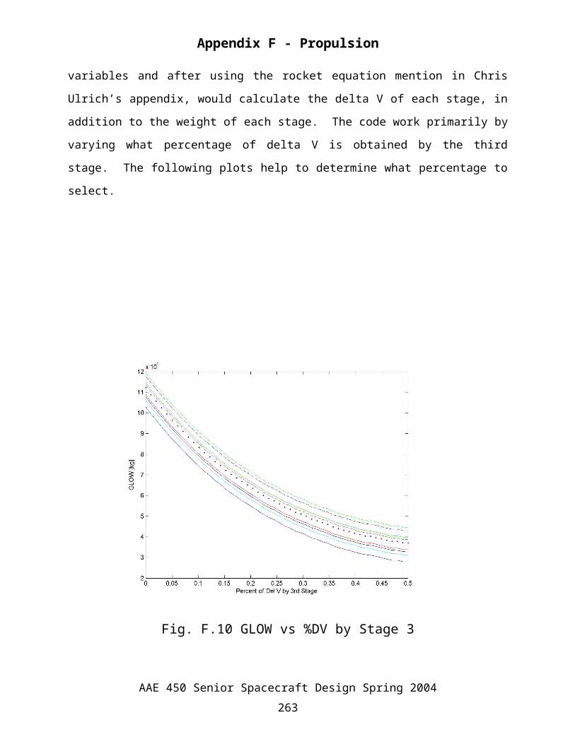
With all the information above, a Matlab code was created. The code is attached. This
code would take the constrained variables and after using the rocket equation mention in Chris
Ulrich’s appendix, would calculate the delta V of each stage, in addition to the weight of each
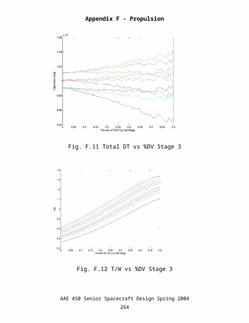
stage. The code work primarily by varying what percentage of delta V is obtained by the third
stage. The following plots help to determine what percentage to select.
Fig. F.10 GLOW vs %DV by Stage 3
AAE 450 Senior Spacecraft Design Spring 2004257
Appendix F - Propulsion
Fig. F.11 Total DT vs %DV Stage 3
Fig. F.12 T/W vs %DV Stage 3
AAE 450 Senior Spacecraft Design Spring 2004258
Appendix F - Propulsion
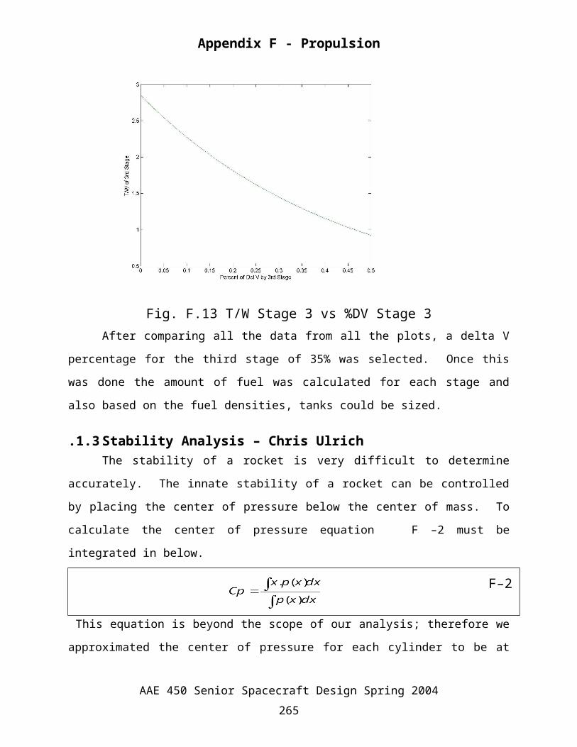
Fig. F.13 T/W Stage 3 vs %DV Stage 3After comparing all the data from all the plots, a delta V percentage for the third stage of
35% was selected. Once this was done the amount of fuel was calculated for each stage and also
based on the fuel densities, tanks could be sized.
F.1.3 Stability Analysis – Chris UlrichThe stability of a rocket is very difficult to determine accurately. The innate stability of a
rocket can be controlled by placing the center of pressure below the center of mass. To calculate
the center of pressure equation F–2 must be integrated in below.
F–2
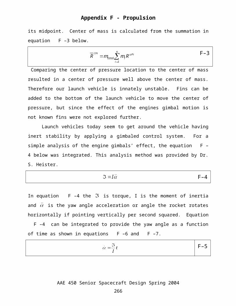
This equation is beyond the scope of our analysis; therefore we approximated the center of
pressure for each cylinder to be at its midpoint. Center of mass is calculated from the summation
in equation F–3 below.
F–3
Comparing the center of pressure location to the center of mass resulted in a center of pressure
well above the center of mass. Therefore our launch vehicle is innately unstable. Fins can be
AAE 450 Senior Spacecraft Design Spring 2004259
Appendix F - Propulsion
added to the bottom of the launch vehicle to move the center of pressure, but since the effect of
the engines gimbal motion is not known fins were not explored further.
Launch vehicles today seem to get around the vehicle having inert stability by applying a
gimbaled control system. For a simple analysis of the engine gimbals’ effect, the equation F–4
below was integrated. This analysis method was provided by Dr. S. Heister.
F–4
In equation F–4 the is torque, I is the moment of inertia and is the yaw angle acceleration or
angle the rocket rotates horizontally if pointing vertically per second squared. Equation F–4 can
be integrated to provide the yaw angle as a function of time as shown in equations F–6 and F–7.
F–5
F–6
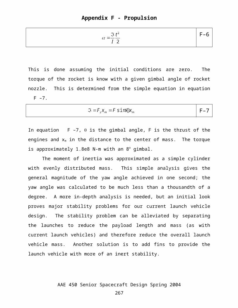
This is done assuming the initial conditions are zero. The torque of the rocket is know with a
given gimbal angle of rocket nozzle. This is determined from the simple equation in equation F–
7.
F–7
In equation F–7, is the gimbal angle, F is the thrust of the engines and xm in the distance to the
center of mass. The torque is approximately 1.8e8 N-m with an 8o gimbal.
The moment of inertia was approximated as a simple cylinder with evenly distributed
mass. This simple analysis gives the general magnitude of the yaw angle achieved in one
second; the yaw angle was calculated to be much less than a thousandth of a degree. A more in-
depth analysis is needed, but an initial look proves major stability problems for our current
launch vehicle design. The stability problem can be alleviated by separating the launches to
reduce the payload length and mass (as with current launch vehicles) and therefore reduce the
AAE 450 Senior Spacecraft Design Spring 2004260
Appendix F - Propulsion
overall launch vehicle mass. Another solution is to add fins to provide the launch vehicle with
more of an inert stability.
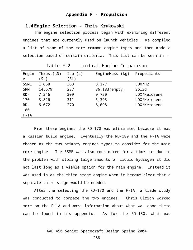
F.1.4 Engine Selection – Chris KrukowskiThe engine selection process began with examining different engines that are currently
used on launch vehicles. We compiled a list of some of the more common engine types and then
made a selection based on certain criteria. This list can be seen in .
Table F.2 Initial Engine ComparisonEngine Thrust(kN) (SL) Isp (s) (SL) EngineMass (kg) PropellantsSSMESRMRD-170RD-180F-1A
1,66814,6797,2463,8266,672
363237309311270
3,17786,183(empty)9,7505,3938,098
LOX/H2SolidLOX/KeroseneLOX/KeroseneLOX/Kerosene
From these engines the RD-170 was eliminated because it was a Russian build engine.
Eventually the RD-180 and the F-1A were chosen as the two primary engines types to consider
for the main core engine. The SSME was also considered for a time but due to the problem with
storing large amounts of liquid hydrogen it did not last long as a viable option for the main
engine. Instead it was used in as the third stage engine when it became clear that a separate third
stage would be needed.
After the selecting the RD-180 and the F-1A, a trade study was conducted to compare the
two engines. Chris Ulrich worked more on the F-1A and more information about what was done
there can be found in his appendix. As for the RD-180, what was originally envisioned was a
central core similar to that of a Saturn V rocket with some SRM engines strapped on.
F.1.5 Tank Sizing – Chris Ulrich The tanks for the launch vehicle were sized using the same method developed my
Marina Mazur. Details of Marina’s method are discussed later in appendix F. The difference in
the analysis for the launch vehicle was the much larger load on the tanks and the different
propellants used with the engines. The different propellant kerosene allowed for a lighter tank to
be used. The lighter tank was Aluminum instead of the stainless steel used by the rest of the
tanks.
AAE 450 Senior Spacecraft Design Spring 2004261
Appendix F - Propulsion
F.2 Transport Vehicle
F.2.1 MITEE-B Engine – Marina MazurMITEE-B has basic radial flow geometry with each fuel element located inside its own
pressure tube. This configuration simplifies engine construction while reducing engine weight.
In addition, since it is possible to be able to test a single pressure tube/fuel element assembly, the
nuclear test program can be simplified and cost and time greatly reduced.
Unlike the PBR, this engine has a multi-layer assembly of perforated tungsten-UO2
cermet fuel sheets. This allows the engine to operate with hydrogen at 3000 K for many hours.
Furthermore, the local voidage and propellant flow geometry is controlled more precisely then in
PBR, which reduces hot channel factors, variation in voidage, and eliminates the chance of
mechanical distortion due to shifts in particle position. Also, due to the fact that the fuel/pressure
elements are housed in individual compartments it is possible to operate the engine even if one of
the elements failed.
In order to produce electric power the heat from the tungsten-UO2 fuel sheets is
transfered to the closed cycle coolant, helium, through the cold frit and its beryllium tubes by
thermal radiation and conduction. The thermal energy is then transported to an external electric
power generation system by the flowing coolant. During this phase, there is no hydrogen
propellant flow through the fuel region.1
F.2.2 Main Engine Tanks – Marina MazurIt was assumed that the stainless steel part of the tank wall will be carrying all of the
loading transferred through the tank wall structure, and that the rest of the tank wall materials
acted as the heat shield materials only. Therefore, the only material thickness that needed to be
adjusted for the current mission was the stainless steel wall thickness. Equation 3-1 was used to
calculate the necessary thickness of stainless steel wall.
The calculations were done using Matlab software, and tank_thickness.m code. The code
can be viewed below. The length of the liquid hydrogen tanks were found using tank_vol.m, and
the total fuel mass was calculated using aae450mrop1.m.
F.2.3 MITEE-B Engine Code
AAE 450 Senior Spacecraft Design Spring 2004262
Appendix F - Propulsion
%**********************************************************************%% aae450mrop1.m%AAE 450 - Spring 2004%Author/s: Marina Mazur%Date Created: 2/5/04%Last Modified: 3/26/04%**********************************************************************%DESCRIPTION%calculates the fuel mass for the MITEE-B
%METHODS OF CALCULATION%using basic rocket equations
%VARIABLES%fr-reservoir propellant as a fraction of the total necessary propellant mass%ft-mass of the propellant tanks, as a proportionality to total propellant mass%mdot – mass flow rate%MR – mass ratio%mprop - propellant mass before the addition of reservoir fuel%time-burn time%engine_mass – mass of engine%mass_tot – total fuel mass%mprop_plus_res – reservoir fuel mass%mdry – dry mass of spacecraft%delv – delta v that needs to be performed%c – effective exhaust velocity%g - gravity%**********************************************************************clear all
%fr and ft are taken from AIAA-2002-3787 Brice N. Cassenti, 'Trajectory%options for Manned mars missionsfr=0.02; %reservoir propellent as a fraction of the total necessary propellent massft=0.03; %mass of the propellent tanks, as a propertionality to total propellant mass
Isp=1300; %secdelv=input('What is your delta v? ');%delv=3+delv+.75
%mdry=input('What is your dry mass? ');mdry=184000;num_engines=input('How many engines? ');%F=input('What is your thrust? ');F=20000;g=9.81; %gravityc=Isp*g; %effective exhaust velocitydelv=delv*1e3;MR=exp(delv/(g*Isp)); %mass ratiomprop=(MR-1)*mdry/(1-ft*(MR-1));
mprop_plus_res=13825; %enough fuel for 6 engines to start.mdot=F*num_engines/c; ; %mass flow rate
AAE 450 Senior Spacecraft Design Spring 2004263
Appendix F - Propulsion
time=mprop/mdot/3600; %time of burn in hours
engine_mass=680*num_engines;mass_tot=engine_mass+mprop_plus_res+mprop;
fprintf('\n\nThe necessary mass of fuel is %f\n',mprop)fprintf('The mass of fuel w/ contigency is %f\n',mprop_plus_res)fprintf('The time of burn is %6.2f hours\n',time)fprintf('The engine weight is %6.2f kg\n',engine_mass)fprintf('Total mass of system is %6.2f kg\n\n',mass_tot)
F.2.4 Main Engine Tank Codes – Marina Mazur
%**********************************************************************%%tank_vol.m%AAE 450 - Spring 2004%Author/s: Marina Mazur%Date Created: 2/10/04%Last Modified: 3/26/04
%**********************************************************************
%DESCRIPTION%calculates the height of the fuel tanks
%METHODS OF CALCULATION%given the density of liquid hydrogen, the fuel weight, and the shape of the tanks, the%height can be found.
%VARIABLES%d – diameter of tank%A – area of tank cross-section%d – diameter of tank%min_mass_in_vol – the minimum fuel mass that must be accommodated%mass – mass of whatever burn is being performed %hight# - height of whatever tank is being looked at %hight_tot – total height of the two tanks%**********************************************************************clcd=10-.1*2 % m diameterA=pi*d^2/4; %area min_mass_in_vol=179600+7000
%%%%%% first burn %%%%%mass=78856; %kgrad=asin(1/5)frac=rad/2/pia_lost=A*fracA=A-a_losthight1=mass/70/A %m%%%%%second burn and third tank and Nicks fuel and extra fuel%%%%mass=63551+7000+13825;hight2=mass/70/A %mhight_tot=hight1+hight2
AAE 450 Senior Spacecraft Design Spring 2004264
Appendix F - Propulsion
%**********************************************************************%AAE 450 - Spring 2004%Author/s: Marina Mazur%Date Created: 3/01/04%Last Modified: 3/26/04%**********************************************************************
%DESCRIPTION%calculates the necessary thickness of stainless steel wall layer
%METHODS OF CALCULATION%the calculation is done using the critical buckling load of the material as the load the system will see. The factor of safety is included in the maximum force the system is under. Factor of safety is 1.5.
%VARIABLES%Fy – yielding load of system%Fu – ulimate load of system%sw and sw1 are used to determine wether Fy or Fu should be looked at for the max.%load the system is can withstand%d – diameter of tank%A2 – area of tank crossection%min_load – actual the minimum load on the system%a_lost - area off tank that is not circular and can not be used for fuel storage%lc – length of tank %tc – wall thickness of stainless steel%r – radius of tank%E – modulus of elasticity%Sc – critical buckling load%A – inside cross-sectional area of tank in ft^2 %A2 - outside cross-sectional area of tank in ft^2%A_tot – total area of stainless steel%vol – volume of stainless steel on the tank%density – density of stainless steel%mass_skin – mass of stainless steel layer
%**********************************************************************clcFy=200000;%psiFu=220000;%psisw=Fy/1.33;sw1=Fu/1.65;if sw1<sw sw=sw1;endd=10-.1*2+.79/37.39; % m diameterA2=pi*d^2/4; %area rad=asin(1/5);frac=rad/2/pi;a_lost=A2*frac; %area lost d A2=A2-a_lost; %TOTAL CYLINDER AREAmin_load=44962 %lbf lc=16.5*37.39; %length of tank inchs
AAE 450 Senior Spacecraft Design Spring 2004265
Appendix F - Propulsion
tc=.79 %in wall thickness stainlessr=5*37.39; %in radius of tankE=31038000; %stainless modulus of Elasticity psiSc=(9*(tc/r)^1.6+.16*(tc/lc)^1.3)*E %critical axial compressive stressA=785.9 %area of tank in ft^2A2=A2*10.7639104A_tot=(A2-A)Vol=A_tot*Lc;density=449; %lb/ft^3mass_skin=density*Vol%**********************************************************************
F.2.5 Engine Selection – Nikolaus LadischIn order for our group to select an engine for the transport vehicle, we wanted a general
relation between the mass of the vehicle, mass of the fuel, engine efficiency (Isp) and the change
in velocity (ΔV). In order to accomplish this, the following equation was derived.
mf = final vehicle mass [kg]mi = initial vehicle mass [kg]
F–8
Isp = Engine efficiency [sec]
go = earth gravity (9.8 m/s2)
F–9
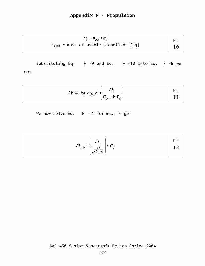
mprop = mass of usable propellant [kg]F–10
Substituting Eq. F–9 and Eq. F–10 into Eq.F–8 we get
F–11
We now solve Eq. F–11 for mprop to get
AAE 450 Senior Spacecraft Design Spring 2004266
0 500 1000 1500 2000 2500 30000
0.5
1
1.5
2
2.5
3
3.5
4
4.5
5x 10
7 Mass of Propellant vs. Engine Efficiency (Isp)
Isp [sec]
Pro
pella
nt M
ass
[kg]
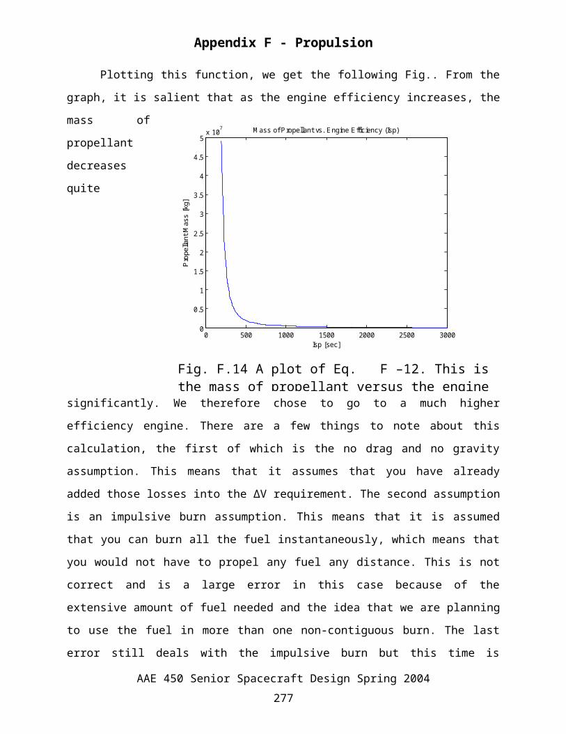
Fig. F.14 A plot of Eq. F–12. This is the mass of propellant versus the engine efficiency.
Appendix F - Propulsion
F–12
Plotting this function, we get the following Fig.. From the graph, it is salient that as the
engine efficiency increases, the mass of propellant decreases quite significantly. We therefore
chose to go to a
much higher
efficiency engine.
There are a few
things to note
about this
calculation, the
first of which is
the no drag and no
gravity
assumption. This
means that it
assumes that you
have already
added those losses
into the ΔV
requirement. The second assumption is an impulsive burn assumption. This means that it is
assumed that you can burn all the fuel instantaneously, which means that you would not have to
propel any fuel any distance. This is not correct and is a large error in this case because of the
extensive amount of fuel needed and the idea that we are planning to use the fuel in more than
one non-contiguous burn. The last error still deals with the impulsive burn but this time is
because as you use the thruster, you would have to do course changes. In general, if the engine is
very high thrust and is burned for a small percentage of the mission, this may be neglected but
with a high thrust engine, you usually end up with a low Isp, which is not what we want. With a
low thrust engine, we can achieve a very high Isp but the fuel savings might not be evident
because of the excess fuel we would have to add for constant course changes.
AAE 450 Senior Spacecraft Design Spring 2004267
Appendix F - Propulsion
F.2.6 Mass Reduction through Engine Stages – Nikolaus LadischOne of the goals of the project was to achieve the lowest mass possible. In earth to orbit
missions, the way to do this is to stage the engines. We therefore decided to look into this
possibility. To accomplish this, we wrote a program that would test different number of stages
and with those, different ΔV requirements for each stage. For instance, it might be very efficient
to provide a small amount of the ΔV at the beginning of the mission using a higher thrust but
lower Isp engine. This intern would reduce the fuel requirement for maneuvering.
Since our mission required three major burns, the burn out of Earth orbit and into Mars
transit, out of Mars orbit into Earth transit and from Earth transit into Earth orbit we decided to
look at a three-stage system. The spacecraft would be launched and assembled with the first two
stages. It would use stage one to get out of earth orbit and into mars transit and after
accomplishing this, eject the first stage. When leaving Mars orbit and going into Earth transit it
would use the second stage, which would remain and be refuelable. The third stage would be
launched separately from earth and sent into a trajectory that would intersect the spacecraft on
its' way back to Earth. Since our mission was planned for a somewhat long duration, the third
stage could be launched well in advance of the mission and use high efficiency but low thrust
engines to slow its velocity and correct its trajectory for a well coordinated and safe mating to
the spacecraft. This would save fuel on stages one and two because they would not have to
propel stage three out of Earth orbit or out of Mars orbit.
Fig. F.15 displays the total propellant mass that would be required for the three-stage
system. This is just a generalized trend for comparison with a dual stage and single stage system.
The model has two large errors. The first is that it never subtracts the ejected stage from the mass
that it has to propel and the second is that it does not take into account that it also has to propel
the fuel needed to do trajectory correction. The lowest propellant mass occurred with the ΔV
breakup of 17% for the first stage, which was an engine with an Isp of 465 (Space Shuttle Main
Engine), 39% for the second stage, which was MITEE-B with an Isp of 1000, and 44% for the
third stage, which was again an engine with an Isp of 465.
AAE 450 Senior Spacecraft Design Spring 2004268
0 500 1000 1500 2000 2500 30000.5
1
1.5
2
2.5
3
3.5
4x 10
6 Total Propellant Mass vs. Delta V Combination
Combination Number
Tot
al P
rope
llant
Mas
s [k
g]
Fig. F.15 Total propellant mass of a three-stage system as a function of different ΔV breakups, which are referenced by a generic number (Combination Number).
Appendix F - Propulsion
Fig. F.16 represents a two-stage version of the previously discussed Fig.. In this scenario,
the minimum propellant ΔV breakup was 78.5% for the stage one engine, which was the
MITEE-B, and 21.5% for stage two, which was an engine with an Isp of 465. The propellant
mass for the three stage scenario was higher than the two stage scenario and likewise, the two
stage scenario was higher mass than the single stage scenario that used the MITEE-B as it’s'
propulsion unit. Although, the propellants for maneuvering would have been less on the
spacecraft due to the decreased fuel for stage one as in the two-stage scenario, we decided that
the risk of docking in transit was higher than any benefit gained by a multi-stage system.
AAE 450 Senior Spacecraft Design Spring 2004269
0 10 20 30 40 50 60 70 800.4
0.6
0.8
1
1.2
1.4
1.6
1.8
2
2.2x 10
6 Total Propellant Mass vs. Delta V Combination
Combination Number
Tot
al P
rope
llant
Mas
s [k
g]
Fig. F.16 Total propellant mass of a two-stage system as a function of different ΔV breakups, which are referenced by a generic number (Combination Number).
Appendix F - Propulsion
F.2.7 Main Engine Database Code – Nikolaus LadischThe following code has a list of common engines and the ability to take inputs such as the
ΔV required and the mass of the vehicle and provide an estimation of the fuel required. This is
only an estimation due to the concerns discussed previously about impulsive burn assumptions.
%%MATLAB CODE CONVENTIONS - Engine Database%AAE 450 - Spring 2004%Author/s: Nikolaus Ladisch%Date Created: 1/21/2004%Last Modified: 3/30/2004%**********************************************************************
%DESCRIPTION%This code generally calculates fuel requirements for a vehicle of a static%mass given a mass and delta V.
%METHODS OF CALCULATION%Standard Rocket Equation, Gravity Free, Drag Free (These can be taken into%account using the delta V
AAE 450 Senior Spacecraft Design Spring 2004270
Appendix F - Propulsion
%CALLED FUNCTIONS%None
%VARIABLES%g - gravity [m/s^2]%deltaV - delta V [km/s]%drymass - mass of vehicle to be moved by specified engine [kg]%engine - number cooresponding to engine selection%thrust - thrust %[N]%Isp - engine efficiency %[sec]%mdot - mass flow rate %[kg/s]%c - characteristic velocity %[m/s]%MR - mass ratio %[unitless]%totalmass - mass of vehicle with engine and propellant %[kg]%propmass - propellant mass %[kg]%time - simple time to target velocity [sec];
%****************************************************************************%PARENT : NIKOLAUS LADISCH%BORN : 1-21-2004%AGE : ~10%PROPULSION%MODIFIED :%NUMEROUS
clear;clc;g = 9.81; %[m/s^2]deltaV = input('HOW MUCH DELTA V IS REQUIRED [km/s] : \n');deltaV=deltaV*1000; %[m/s]clc;drymass = input('WHAT IS THE DRY MASS OF THE VEHICLE [kg] : \n');clc;fprintf('1 - RD-180\n');fprintf('2 - SSME\n');fprintf('3 - RD-0146\n');fprintf('4 - RL60\n');fprintf('5 - NTR\n');fprintf('6 - EP\n');fprintf('7 - ESCORT\n');fprintf('8 - NERVA\n');fprintf('9 - NERVA2\n');fprintf('10 - Prectical Bed\n');fprintf('11 - TRW OMV Variable Thrust\n');fprintf('12 - Aerojet Shuttle OMS\n');fprintf('13 - Marquardt R-40B\n');fprintf('14 - P&W T220HT Hall Effect Thruster\n');fprintf('\n');engine=input('PLEASE CHOOSE THE ENGINE YOU WANT : \n');clc;fprintf('\n');switch enginecase 1 fprintf('RD-180'); % dry mass - 5480 kg, 12081 lb % Kerosene, Oxygen
AAE 450 Senior Spacecraft Design Spring 2004271
Appendix F - Propulsion
thrust = 3825470; %[N] 860000 [lb] Isp = 337; %[sec] mdot = thrust/(Isp*g); %[kg/s] c = thrust/mdot; %[m/s] MR = exp(deltaV/(-1*c)); %[unitless] totalmass=drymass/MR; %[kg] propmass=totalmass-drymass; %[kg] time=(thrust/(totalmass*deltaV))^-1; clc; fprintf('RD-180\n'); fprintf('vehicle dry mass - %f - kg\n',totalmass-propmass); fprintf('propellant mass - %f - kg\n',propmass); fprintf('total mass - %f - kg\n',totalmass); fprintf('approximate time to accelerate - %f - sec',time);case 2 fprintf('SSME'); % dry mass - kg, lb thrust = 2278000; %[N] [lb] Isp = 453; %[sec] mdot = thrust/(Isp*g); %[kg/s] c = thrust/mdot; %[m/s] MR = exp(deltaV/(-1*c)); %[unitless] totalmass=drymass/MR; %[kg] propmass=totalmass-drymass; %[kg] time=(thrust/(totalmass*deltaV))^-1; clc; fprintf('SSME\n'); fprintf('vehicle dry mass - %f - kg\n',totalmass-propmass); fprintf('propellant mass - %f - kg\n',propmass); fprintf('total mass - %f - kg\n',totalmass); fprintf('approximate time to accelerate - %f - sec',time); case 3 fprintf('RD-0146'); %dry mass - 2,375 kg, 534 lb thrust = 97860; %[N] 22000 [lb] Isp = 451; %[sec] mdot = thrust/(Isp*g); %[kg/s] c = thrust/mdot; %[m/s] MR = exp(deltaV/(-1*c)); %[unitless] totalmass=drymass/MR; %[kg] propmass=totalmass-drymass; %[kg] time=(thrust/(totalmass*deltaV))^-1; clc; fprintf('RD-0146\n'); fprintf('vehicle dry mass - %f - kg\n',totalmass-propmass); fprintf('propellant mass - %f - kg\n',propmass); fprintf('total mass - %f - kg\n',totalmass); fprintf('approximate time to accelerate - %f - sec',time);case 4 fprintf('RL60'); % dry mass - 4,893 kg, 1100 lb thrust = 289134; %[N] 65000 [lb] Isp = 465; %[sec] mdot = thrust/(Isp*g); %[kg/s] c = thrust/mdot; %[m/s] MR = exp(deltaV/(-1*c)); %[unitless] totalmass=drymass/MR; %[kg]
AAE 450 Senior Spacecraft Design Spring 2004272
Appendix F - Propulsion
propmass=totalmass-drymass; %[kg] time=(thrust/(totalmass*deltaV))^-1; clc; fprintf('RL60\n'); fprintf('vehicle dry mass - %f - kg\n',totalmass-propmass); fprintf('propellant mass - %f - kg\n',propmass); fprintf('total mass - %f - kg\n',totalmass); fprintf('approximate time to accelerate - %f - sec',time); case 5 fprintf('NTR'); % dry mass - kg, lb thrust = 20000; %[N] [lb] Isp = 1000; %[sec] mdot = thrust/(Isp*g); %[kg/s] c = thrust/mdot; %[m/s] MR = exp(deltaV/(-1*c)); %[unitless] totalmass=drymass/MR; %[kg] propmass=totalmass-drymass; %[kg] time=(thrust/(totalmass*deltaV))^-1; clc; fprintf('NTR\n'); fprintf('vehicle dry mass - %f - kg\n',totalmass-propmass); fprintf('propellant mass - %f - kg\n',propmass); fprintf('total mass - %f - kg\n',totalmass); fprintf('approximate time to accelerate - %f - sec',time);
case 6 fprintf('EP'); % dry mass - kg, lb thrust = 1; %[N] [lb] Isp = 10000; %[sec] mdot = thrust/(Isp*g); %[kg/s] c = thrust/mdot; %[m/s] MR = exp(deltaV/(-1*c)); %[unitless] totalmass=drymass/MR; %[kg] propmass=totalmass-drymass; %[kg] time=(thrust/(totalmass*deltaV))^-1; clc; fprintf('EP\n'); fprintf('vehicle dry mass - %f - kg\n',totalmass-propmass); fprintf('propellant mass - %f - kg\n',propmass); fprintf('total mass - %f - kg\n',totalmass); fprintf('approximate time to accelerate - %f - sec',time); case 7 fprintf('ESCORT'); % dry mass - kg, lb thrust = 20000; %[N] [lb] Isp = 1000; %[sec] mdot = thrust/(Isp*g); %[kg/s] c = thrust/mdot; %[m/s] MR = exp(deltaV/(-1*c)); %[unitless] totalmass=drymass/MR; %[kg] propmass=totalmass-drymass; %[kg] time=(thrust/(totalmass*deltaV))^-1; clc; fprintf('ESCORT\n'); fprintf('vehicle dry mass - %f - kg\n',totalmass-propmass);
AAE 450 Senior Spacecraft Design Spring 2004273
Appendix F - Propulsion
fprintf('propellant mass - %f - kg\n',propmass); fprintf('total mass - %f - kg\n',totalmass); fprintf('approximate time to accelerate - %f - sec',time);case 8 fprintf('NERVA'); % dry mass - kg, lb
thrust = 333000; %[N] [lb] Isp = 825; %[sec] mdot = thrust/(Isp*g); %[kg/s] c = thrust/mdot; %[m/s] MR = exp(deltaV/(-1*c)); %[unitless] totalmass=drymass/MR; %[kg] propmass=totalmass-drymass; %[kg] time=(thrust/(totalmass*deltaV))^-1; clc; fprintf('NTR\n'); fprintf('vehicle dry mass - %f - kg\n',totalmass-propmass); fprintf('propellant mass - %f - kg\n',propmass); fprintf('total mass - %f - kg\n',totalmass); fprintf('approximate time to accelerate - %f - sec',time);case 9 fprintf('NERVA2'); % dry mass - kg, lb thrust = 1000000; %[N] [lb] Isp = 850; %[sec] mdot = thrust/(Isp*g); %[kg/s] c = thrust/mdot; %[m/s] MR = exp(deltaV/(-1*c)); %[unitless] totalmass=drymass/MR; %[kg] propmass=totalmass-drymass; %[kg] time=(thrust/(totalmass*deltaV))^-1; clc; fprintf('NTR\n'); fprintf('vehicle dry mass - %f - kg\n',totalmass-propmass); fprintf('propellant mass - %f - kg\n',propmass); fprintf('total mass - %f - kg\n',totalmass); fprintf('approximate time to accelerate - %f - sec',time); case 10 fprintf('Practical Bed'); % dry mass - kg, lb thrust = 1000000; %[N] [lb] Isp = 1004; %[sec] mdot = thrust/(Isp*g); %[kg/s] c = thrust/mdot; %[m/s] MR = exp(deltaV/(-1*c)); %[unitless] totalmass=drymass/MR; %[kg] propmass=totalmass-drymass; %[kg] time=(thrust/(totalmass*deltaV))^-1; clc; fprintf('NTR\n'); fprintf('vehicle dry mass - %f - kg\n',totalmass-propmass); fprintf('propellant mass - %f - kg\n',propmass); fprintf('total mass - %f - kg\n',totalmass); fprintf('approximate time to accelerate - %f - sec',time); case 11 fprintf('TRW OMV Variable Thrust');
AAE 450 Senior Spacecraft Design Spring 2004274
Appendix F - Propulsion
% dry mass - kg, lb thrust = 578; %[N] [lb] Isp = 308; %[sec] mdot = thrust/(Isp*g); %[kg/s] c = thrust/mdot; %[m/s] MR = exp(deltaV/(-1*c)); %[unitless] totalmass=drymass/MR; %[kg] propmass=totalmass-drymass; %[kg] time=(thrust/(totalmass*deltaV))^-1; clc; fprintf('TRW OMV Variable Thrust\n'); fprintf('vehicle dry mass - %f - kg\n',totalmass-propmass); fprintf('propellant mass - %f - kg\n',propmass); fprintf('total mass - %f - kg\n',totalmass); fprintf('approximate time to accelerate - %f - sec',time); case 12 fprintf('Aerojet Shuttle OMS'); % dry mass - kg, lb
thrust = 26700; %[N] [lb] Isp = 316; %[sec] mdot = thrust/(Isp*g); %[kg/s] c = thrust/mdot; %[m/s] MR = exp(deltaV/(-1*c)); %[unitless] totalmass=drymass/MR; %[kg] propmass=totalmass-drymass; %[kg] time=(thrust/(totalmass*deltaV))^-1; clc; fprintf('Aerojet Shuttle OMS\n'); fprintf('vehicle dry mass - %f - kg\n',totalmass-propmass); fprintf('propellant mass - %f - kg\n',propmass); fprintf('total mass - %f - kg\n',totalmass); fprintf('approximate time to accelerate - %f - sec',time); case 13 fprintf('Marquardt R-40B'); % dry mass - kg, lb
thrust = 16000; %[N] [lb] Isp = 303; %[sec] mdot = thrust/(Isp*g); %[kg/s] c = thrust/mdot; %[m/s] MR = exp(deltaV/(-1*c)); %[unitless] totalmass=drymass/MR; %[kg] propmass=totalmass-drymass; %[kg] time=(thrust/(totalmass*deltaV))^-1; clc; fprintf('Marquardt R-40B\n'); fprintf('vehicle dry mass - %f - kg\n',totalmass-propmass); fprintf('propellant mass - %f - kg\n',propmass); fprintf('total mass - %f - kg\n',totalmass); fprintf('approximate time to accelerate - %f - sec',time); case 14 fprintf('Hall Effect Thruster P&W T220HT'); thrust = 1.00; %[N] [lb] Isp = 2500; %[sec] mdot = thrust/(Isp*g); %[kg/s] c = thrust/mdot; %[m/s]
AAE 450 Senior Spacecraft Design Spring 2004275
Appendix F - Propulsion
MR = exp(deltaV/(-1*c)); %[unitless] totalmass=drymass/MR; %[kg] propmass=totalmass-drymass; %[kg] time=(thrust/(totalmass*deltaV))^-1; clc; fprintf('TEST\n'); fprintf('vehicle dry mass - %f - kg\n',totalmass-propmass); fprintf('propellant mass - %f - kg\n',propmass); fprintf('total mass - %f - kg\n',totalmass); fprintf('approximate time to accelerate - %f - sec',time); end
F.2.8 Probe Engine Code – Nikolaus LadischThe following code was generated in order to predict the fuel mass for each probe. It
allowed us to choose the proper tanks and then reiterate to get a new fuel mass.
%%MATLAB CODE CONVENTIONS - Probe Engine Designer%AAE 450 - Spring 2004%Author/s: Nikolaus Ladisch%Date Created: 3/25/2004%Last Modified: 3/25/2004
%****************************************************************************
%DESCRIPTION%This code generally calculates fuel requirements for a vehicle of a static%mass given a mass and delta V.
%METHODS OF CALCULATION%Standard Rocket Equation, Gravity Free, Drag Free (These can be taken into%account using the delta V
%CALLED FUNCTIONS%None
%VARIABLES%deltaV - delta V [km/s]%F - thrust %[N]%Isp - engine efficiency %[sec]%g - gravity [m/s^2]%m_engine - mass of engine [kg]%m_tanks - mass of tanks [kg]%mdot - mass flow rate [kg/sec]%dV_a - delta V attained %time - time [sec]%m_propellant - mass of propellant [kg]%m_fuel=mass of fuel %[kg]%V_fuel=volume of fuel %[m^3]%D_fueltank=diameter of fuel tank %[m]%m_oxidizer=mass of oxidizer [kg];%V_oxidizer=volume of oxidizer [m^3];%D_oxtank=diameter of oxidizer tank [m]
AAE 450 Senior Spacecraft Design Spring 2004276
Appendix F - Propulsion
clear;clc;close all;%PROPERTIESg=9.8; %[m/s]
%PROBE CHARACTERISTICSm_payload=4; %[kg]
%DELTA V REQUIREMENTSdV=781.9; %[m/s]
%ENGINE SPECSm_engine=1; %[kg]m_tanks=2.6; %[kg] two tanks at 3.7 kg a piece volume ~1800 in^3Isp=290; %[sec]F=22; %[N]mdot=F/(Isp*g);
dV_a=0;count=1;
while dV_a(count)<dV time(count)=count; if count>1 m_propellant(count)=m_propellant(count-1)+mdot; else m_propellant(count)=mdot; end m_total(count)=m_engine+m_tanks+m_propellant(count)+m_payload; a(count)=F/m_total(count); if count>1 dV_a(count+1)=dV_a(count)+a(count); else dV_a(count+1)=a(count); end count=count+1;end
Fig.(1);plot(time,a);title('Acceleration vs. Time');xlabel('Time');ylabel('Acceleration [m/s^2]');
Fig.(2);plot(time,dV_a(2:length(dV_a)));title('Delta V attained vs. Time');
Fig.(3);plot(time,m_propellant);title('Mass of Propellant vs. Time');
Fig.(4);plot(time,m_total);title('Total Mass vs. Time');
AAE 450 Senior Spacecraft Design Spring 2004277
Appendix F - Propulsion
m_fuel=m_propellant(length(m_propellant))/2.6; %[kg]V_fuel=m_fuel/880; %[m^3]D_fueltank=2*(V_fuel*(3/4)*(1/pi))^(1/3); %[m]
m_oxidizer=m_fuel*1.6;V_oxidizer=m_oxidizer/1450;D_oxtank=2*(V_oxidizer*(3/4)*(1/pi))^(1/3); %[m]
fprintf('The mass of fuel is %f\n',m_fuel);fprintf('The volume of fuel is %f\n',V_fuel);fprintf('The volume of the fuel in ci is %f\n',V_fuel*61023);fprintf('The diameter of the fuel tank is %f\n',D_fueltank);
fprintf('The mass of oxidizer is %f\n',m_oxidizer);fprintf('The volume of oxidizer is %f\n',V_oxidizer);fprintf('The volume of the oxidizer in ci is %f\n',V_oxidizer*61023);fprintf('The diameter of the oxidizer tank is %f\n',D_oxtank);
AAE 450 Senior Spacecraft Design Spring 2004278
Appendix F - Propulsion
This extra blank page must be here because of the “Section Break”. It is important that the section break be here so that each section can be combined for the final
document.
2 Sutton, G. P., Bivlarz, O. Fundamentals of Rocket Propulsion, 7th ed., Wiley-Interscience, New York, 2001, 426. 3Shelton, B. W., T. Murphy . "The Saturn V F-1 Engine Revisited." AIAA 92-1547. Huntsville, Alabama. 24-27 March 1992. < http://www.marsinstitute.info/rd/faculty/dportree/rtr/ap37.html>
AAE 450 Senior Spacecraft Design Spring 2004279