Automotive grade High current power inductors · 2020-02-26 · Part Number Definition:...
12
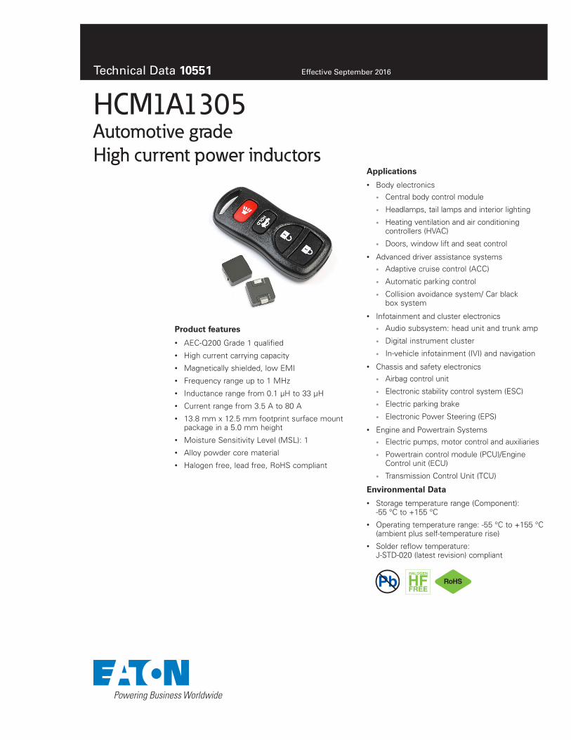
Technical Data 10551 Effective September 2016 HCM1A1305 Automotive grade High current power inductors Product features • AEC-Q200 Grade 1 qualified • High current carrying capacity • Magnetically shielded, low EMI • Frequency range up to 1 MHz • Inductance range from 0.1 μH to 33 μH • Current range from 3.5 A to 80 A • 13.8 mm x 12.5 mm footprint surface mount package in a 5.0 mm height • Moisture Sensitivity Level (MSL): 1 • Alloy powder core material • Halogen free, lead free, RoHS compliant Applications • Body electronics • Central body control module • Headlamps, tail lamps and interior lighting • Heating ventilation and air conditioning controllers (HVAC) • Doors, window lift and seat control • Advanced driver assistance systems • Adaptive cruise control (ACC) • Automatic parking control • Collision avoidance system/ Car black box system • Infotainment and cluster electronics • Audio subsystem: head unit and trunk amp • Digital instrument cluster • In-vehicle infotainment (IVI) and navigation • Chassis and safety electronics • Airbag control unit • Electronic stability control system (ESC) • Electric parking brake • Electronic Power Steering (EPS) • Engine and Powertrain Systems • Electric pumps, motor control and auxiliaries • Powertrain control module (PCU)/Engine Control unit (ECU) • Transmission Control Unit (TCU) Environmental Data • Storage temperature range (Component): -55 °C to +155 °C • Operating temperature range: -55 °C to +155 °C (ambient plus self-temperature rise) • Solder reflow temperature: J-STD-020 (latest revision) compliant Pb HALOGEN HF FREE
Transcript of Automotive grade High current power inductors · 2020-02-26 · Part Number Definition:...
Technical Data 10551 Effective September 2016
HCM1A1305Automotive grade High current power inductors
Product features
• AEC-Q200 Grade 1 qualified
• High current carrying capacity
• Magnetically shielded, low EMI
• Frequency range up to 1 MHz
• Inductance range from 0.1 μH to 33 μH
• Current range from 3.5 A to 80 A
• 13.8 mm x 12.5 mm footprint surface mount package in a 5.0 mm height
• Moisture Sensitivity Level (MSL): 1
• Alloy powder core material
• Halogen free, lead free, RoHS compliant
Applications
• Body electronics
• Central body control module
• Headlamps, tail lamps and interior lighting
• Heating ventilation and air conditioning controllers (HVAC)
• Doors, window lift and seat control
• Advanced driver assistance systems
• Adaptive cruise control (ACC)
• Automatic parking control
• Collision avoidance system/ Car black box system
• Infotainment and cluster electronics
• Audio subsystem: head unit and trunk amp
• Digital instrument cluster
• In-vehicle infotainment (IVI) and navigation
• Chassis and safety electronics
• Airbag control unit
• Electronic stability control system (ESC)
• Electric parking brake
• Electronic Power Steering (EPS)
• Engine and Powertrain Systems
• Electric pumps, motor control and auxiliaries
• Powertrain control module (PCU)/Engine Control unit (ECU)
• Transmission Control Unit (TCU)
Environmental Data
• Storage temperature range (Component): -55 °C to +155 °C
• Operating temperature range: -55 °C to +155 °C (ambient plus self-temperature rise)
• Solder reflow temperature: J-STD-020 (latest revision) compliant
PbHALOGEN
HFFREE
2
Technical Data 10551Effective September 2016
HCM1A1305Automotive grade high current power inductors
www.eaton.com/electronics
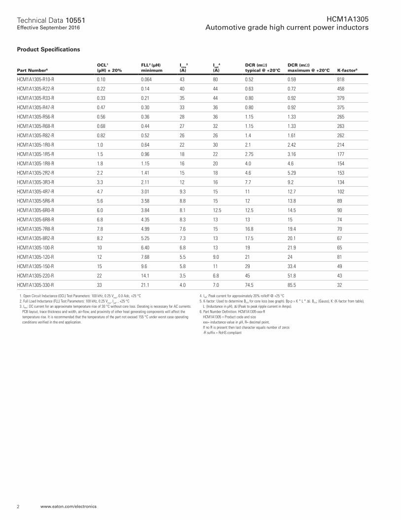
Product Specifications
Part Number6
OCL1 (μH) ± 20%
FLL2 (μH) minimum
Irms3
(A)Isat
4 (A)
DCR (mΩ) typical @ +20°C
DCR (mΩ) maximum @ +20°C K-factor5
HCM1A1305-R10-R 0.10 0.064 43 80 0.52 0.59 818
HCM1A1305-R22-R 0.22 0.14 40 44 0.63 0.72 458
HCM1A1305-R33-R 0.33 0.21 35 44 0.80 0.92 379
HCM1A1305-R47-R 0.47 0.30 33 36 0.80 0.92 375
HCM1A1305-R56-R 0.56 0.36 28 36 1.15 1.33 265
HCM1A1305-R68-R 0.68 0.44 27 32 1.15 1.33 263
HCM1A1305-R82-R 0.82 0.52 26 26 1.4 1.61 262
HCM1A1305-1R0-R 1.0 0.64 22 30 2.1 2.42 214
HCM1A1305-1R5-R 1.5 0.96 18 22 2.75 3.16 177
HCM1A1305-1R8-R 1.8 1.15 16 20 4.0 4.6 154
HCM1A1305-2R2-R 2.2 1.41 15 18 4.6 5.29 153
HCM1A1305-3R3-R 3.3 2.11 12 16 7.7 9.2 134
HCM1A1305-4R7-R 4.7 3.01 9.3 15 11 12.7 102
HCM1A1305-5R6-R 5.6 3.58 8.8 15 12 13.8 89
HCM1A1305-6R0-R 6.0 3.84 8.1 12.5 12.5 14.5 90
HCM1A1305-6R8-R 6.8 4.35 8.3 13 13 15 74
HCM1A1305-7R8-R 7.8 4.99 7.6 15 16.8 19.4 70
HCM1A1305-8R2-R 8.2 5.25 7.3 13 17.5 20.1 67
HCM1A1305-100-R 10 6.40 6.8 13 19 21.9 65
HCM1A1305-120-R 12 7.68 5.5 9.0 21 24 81
HCM1A1305-150-R 15 9.6 5.8 11 29 33.4 49
HCM1A1305-220-R 22 14.1 3.5 6.8 45 51.8 43
HCM1A1305-330-R 33 21.1 4.0 7.0 74.5 85.5 32
1. Open Circuit Inductance (OCL) Test Parameters: 100 kHz, 0.25 Vrms, 0.0 Adc, +25 °C2. Full Load Inductance (FLL) Test Parameters: 100 kHz, 0.25 Vrms, Isat, , +25 °C3. Irms: DC current for an approximate temperature rise of 30 °C without core loss. Derating is necessary for AC currents.
PCB layout, trace thickness and width, air-flow, and proximity of other heat generating components will affect the temperature rise. It is recommended that the temperature of the part not exceed 155 °C under worst case operating conditions verified in the end application.
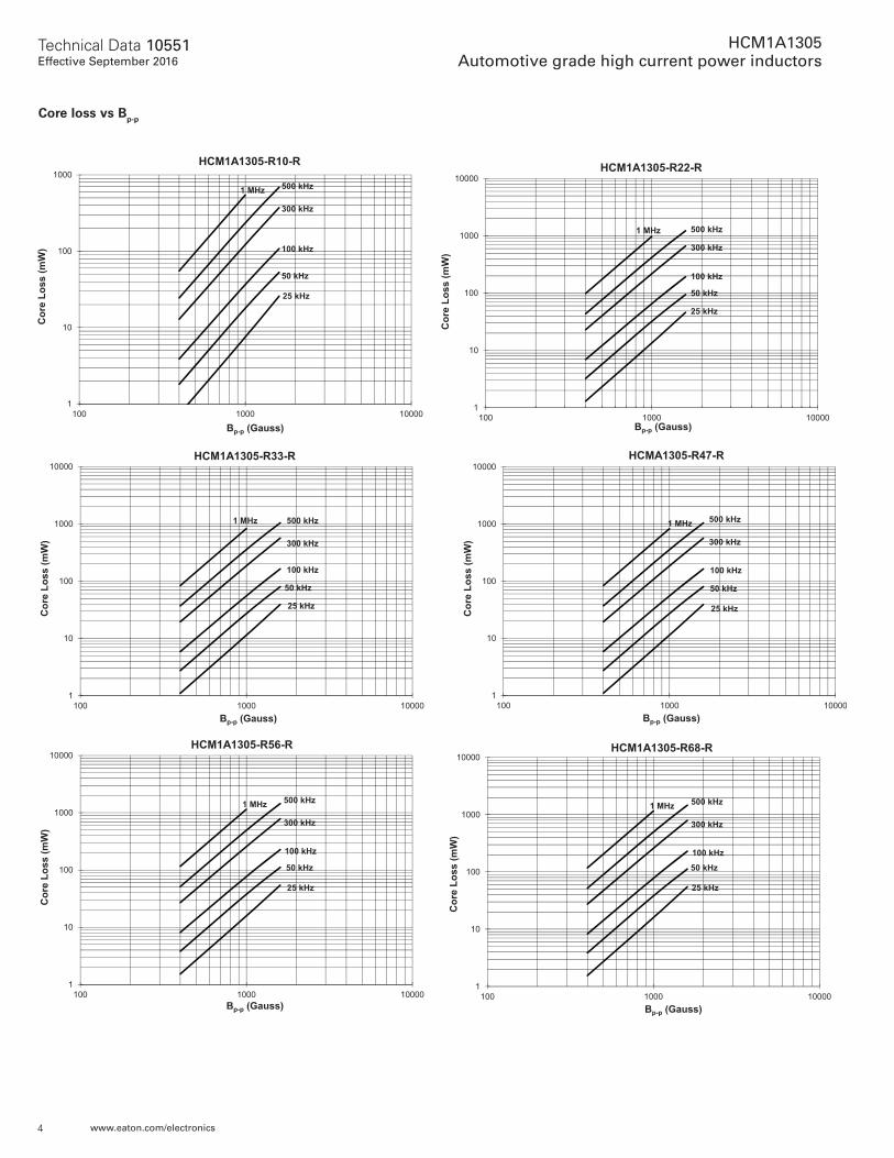
4. Isat: Peak current for approximately 20% rolloff @ +25 °C5. K-factor: Used to determine Bp-p for core loss (see graph). Bp-p = K * L * ΔI. Bp-p: (Gauss), K: (K-factor from table),
L: (Inductance in μH), ΔI (Peak to peak ripple current in Amps).6. Part Number Definition: HCM1A1305-xxx-R
HCM1A1305 = Product code and size xxx= inductance value in μH, R= decimal point, If no R is present then last character equals number of zeros -R suffix = RoHS compliant
3
Technical Data 10551Effective September 2016
HCM1A1305Automotive grade high current power inductors
www.eaton.com/electronics
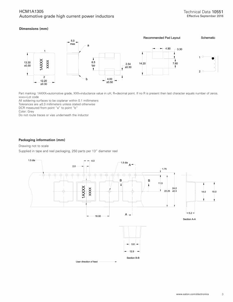
Packaging information (mm)
Drawing not to scale
Supplied in tape and reel packaging, 250 parts per 13” diameter reel
Part marking: 1AXXX=automotive grade, XXX=inductance value in uH, R=decimal point. If no R is present then last character equals number of zeros. xxxx=Lot code All soldering surfaces to be coplanar within 0.1 millimeters Tolerances are ±0.3 millimeters unless stated otherwise DCR measured from point “a” to point “b” Color: Grey Do not route traces or vias underneath the inductor
Dimensions (mm)
xxxx
xxxx
4
Technical Data 10551Effective September 2016
HCM1A1305Automotive grade high current power inductors
www.eaton.com/electronics
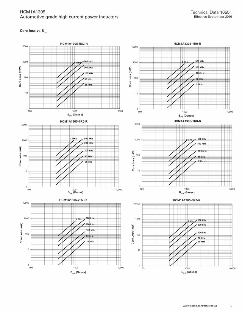
Core loss vs Bp-p
1
10
100
1000
000010001001
Cor
e Lo
ss (m
W)
Bp-p (Gauss)
HCM1A1305-R10-R
1 MHz 500 kHz
300 kHz
100 kHz
50 kHz
25 kHz
1
10
100
1000
10000
000010001001
Cor
e Lo
ss (m
W)
Bp-p (Gauss)
HCM1A1305-R22-R
1 MHz 500 kHz
300 kHz
100 kHz
50 kHz
25 kHz
1
10
100
1000
10000
000010001001
Cor
e Lo
ss (m
W)
Bp-p (Gauss)
HCM1A1305-R33-R
1 MHz 500 kHz
300 kHz
100 kHz
50 kHz
25 kHz
1
10
100
1000
10000
000010001001
Cor
e Lo
ss (m
W)
Bp-p (Gauss)
HCMA1305-R47-R
1 MHz 500 kHz
300 kHz
100 kHz
50 kHz
25 kHz
1
10
100
1000
10000
000010001001
Cor
e Lo
ss (m
W)
Bp-p (Gauss)
HCM1A1305-R56-R
1 MHz 500 kHz
300 kHz
100 kHz
50 kHz
25 kHz
1
10
100
1000
10000
000010001001
Cor
e Lo
ss (m
W)
Bp-p (Gauss)
HCM1A1305-R68-R
1 MHz 500 kHz
300 kHz
100 kHz
50 kHz
25 kHz
5
Technical Data 10551Effective September 2016
HCM1A1305Automotive grade high current power inductors
www.eaton.com/electronics
Core loss vs Bp-p
1
10
100
1000
10000
000010001001
Cor
e Lo
ss (m
W)
Bp-p (Gauss)
HCM1A1305-R82-R
1 MHz 500 kHz
300 kHz
100 kHz
50 kHz
25 kHz
1
10
100
1000
10000
000010001001
Cor
e Lo
ss (m
W)
Bp-p (Gauss)
HCM1A1305-1R0-R
1 MHz 500 kHz
300 kHz
100 kHz
50 kHz
25 kHz
1
10
100
1000
10000
000010001001
Cor
e Lo
ss (m
W)
Bp-p (Gauss)
HCM1A1305-1R5-R
1 MHz 500 kHz
300 kHz
100 kHz
50 kHz
25 kHz
1
10
100
1000
10000
000010001001
Cor
e Lo
ss (m
W)
Bp-p (Gauss)
HCM1A1305-1R8-R
1 MHz 500 kHz
300 kHz
100 kHz
50 kHz
25 kHz
1
10
100
1000
10000
000010001001
Cor
e Lo
ss (m
W)
Bp-p (Gauss)
HCM1A1305-2R2-R
1 MHz 500 kHz
300 kHz
100 kHz
50 kHz
25 kHz
1
10
100
1000
10000
000010001001
Cor
e Lo
ss (m
W)
Bp-p (Gauss)
HCM1A1305-3R3-R
1 MHz 500 kHz
300 kHz
100 kHz
50 kHz25 kHz
6
Technical Data 10551Effective September 2016
HCM1A1305Automotive grade high current power inductors
www.eaton.com/electronics
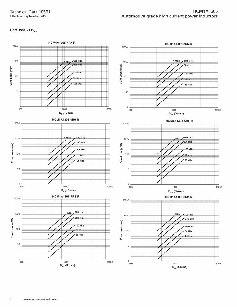
Core loss vs Bp-p
1
10
100
1000
10000
000010001001
Cor
e Lo
ss (m
W)
Bp-p (Gauss)
HCM1A1305-4R7-R
1 MHz 500 kHz300 kHz
100 kHz
50 kHz
25 kHz
1
10
100
1000
10000
000010001001
Cor
e Lo
ss (m
W)
Bp-p (Gauss)
HCM1A1305-5R6-R
1 MHz 500 kHz
300 kHz
100 kHz
50 kHz
25 kHz
1
10
100
1000
10000
000010001001
Cor
e Lo
ss (m
W)
Bp-p (Gauss)
HCM1A1305-6R0-R
1 MHz 500 kHz
300 kHz
100 kHz
50 kHz
25 kHz
1
10
100
1000
10000
000010001001
Cor
e Lo
ss (m
W)
Bp-p (Gauss)
HCM1A1305-6R8-R
1 MHz 500 kHz
300 kHz
100 kHz
50 kHz
25 kHz
1
10
100
1000
10000
000010001001
Cor
e Lo
ss (m
W)
Bp-p (Gauss)
HCM1A1305-7R8-R
1 MHz 500 kHz
300 kHz
100 kHz
50 kHz
25 kHz
1
10
100
1000
10000
000010001001
Cor
e Lo
ss (m
W)
Bp-p (Gauss)
HCM1A1305-8R2-R
1 MHz 500 kHz
300 kHz
100 kHz
50 kHz
25 kHz

7
Technical Data 10551Effective September 2016
HCM1A1305Automotive grade high current power inductors
www.eaton.com/electronics
1
10
100
1000
10000
000010001001
Cor
e Lo
ss (m
W)
Bp-p (Gauss)
HCM1A1305-330-R
1 MHz 500 kHz
300 kHz
100 kHz
50 kHz
25 kHz
1
10
100
1000
10000
000010001001
Cor
e Lo
ss (m
W)
Bp-p (Gauss)
HCM1A1305-100-R
1 MHz 500 kHz
300 kHz
100 kHz
50 kHz
25 kHz
1
10
100
1000
10000
000010001001
Cor
e Lo
ss (m
W)
Bp-p (Gauss)
HCM1A1305-120-R
1 MHz 500 kHz
300 kHz
100 kHz
50 kHz
25 kHz
1
10
100
1000
10000
000010001001
Cor
e Lo
ss (m
W)
Bp-p (Gauss)
HCM1A1305-150-R
1 MHz 500 kHz
300 kHz
100 kHz
50 kHz
25 kHz
1
10
100
1000
10000
000010001001
Cor
e Lo
ss (m
W)
Bp-p (Gauss)
HCM1A1305-220-R
1 MHz 500 kHz
300 kHz
100 kHz
50 kHz
25 kHz
Core loss vs Bp-p
8
Technical Data 10551Effective September 2016
HCM1A1305Automotive grade high current power inductors
www.eaton.com/electronics
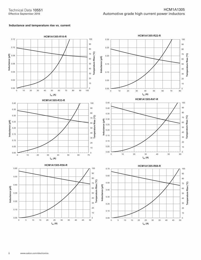
Inductance and temperature rise vs. current
0
10
20
30
40
50
60
70
80
90
100
0.00
0.02
0.04
0.06
0.08
0.10
0.12
0 10 20 30 40 50 60 70 80 90 100
Tem
pera
ture
Ris
e (°
C)
Indu
ctan
ce (μ
H)
Idc (A)
HCM1A1305-R10-R
0
10
20
30
40
50
60
70
80
90
100
0.00
0.05
0.10
0.15
0.20
0.25
0.30
0 10 20 30 40 50 60 70 80
Tem
pera
ture
Ris
e (°
C)
Indu
ctan
ce (μ
H)
Idc (A)
HCM1A1305-R22-R
0
10
20
30
40
50
60
70
80
90
100
0.00
0.05
0.10
0.15
0.20
0.25
0.30
0.35
0.40
0 10 20 30 40 50 60 70
Tem
pera
ture
Ris
e (°
C)
Indu
ctan
ce (μ
H)
Idc (A)
HCM1A1305-R33-R
0
10
20
30
40
50
60
70
80
90
100
0.00
0.05
0.10
0.15
0.20
0.25
0.30
0.35
0.40
0.45
0 10 20 30 40 50 60
Tem
pera
ture
Ris
e (°
C)
Indu
ctan
ce (μ
H)
Idc (A)
HCM1A1305-R47-R
0
10
20
30
40
50
60
70
80
90
100
0.00
0.10
0.20
0.30
0.40
0.50
0.60
0 5 10 15 20 25 30 35 40 45 50
Tem
pera
ture
Ris
e (°
C)
Indu
ctan
ce (μ
H)
Idc (A)
HCM1A1305-R56-R
0
10
20
30
40
50
60
70
80
90
100
0.00
0.10
0.20
0.30
0.40
0.50
0.60
0.70
0 5 10 15 20 25 30 35 40 45 50
Tem
pera
ture
Ris
e (°
C)
Indu
ctan
ce (μ
H)
Idc (A)
HCM1A1305-R68-R
9
Technical Data 10551Effective September 2016
HCM1A1305Automotive grade high current power inductors
www.eaton.com/electronics
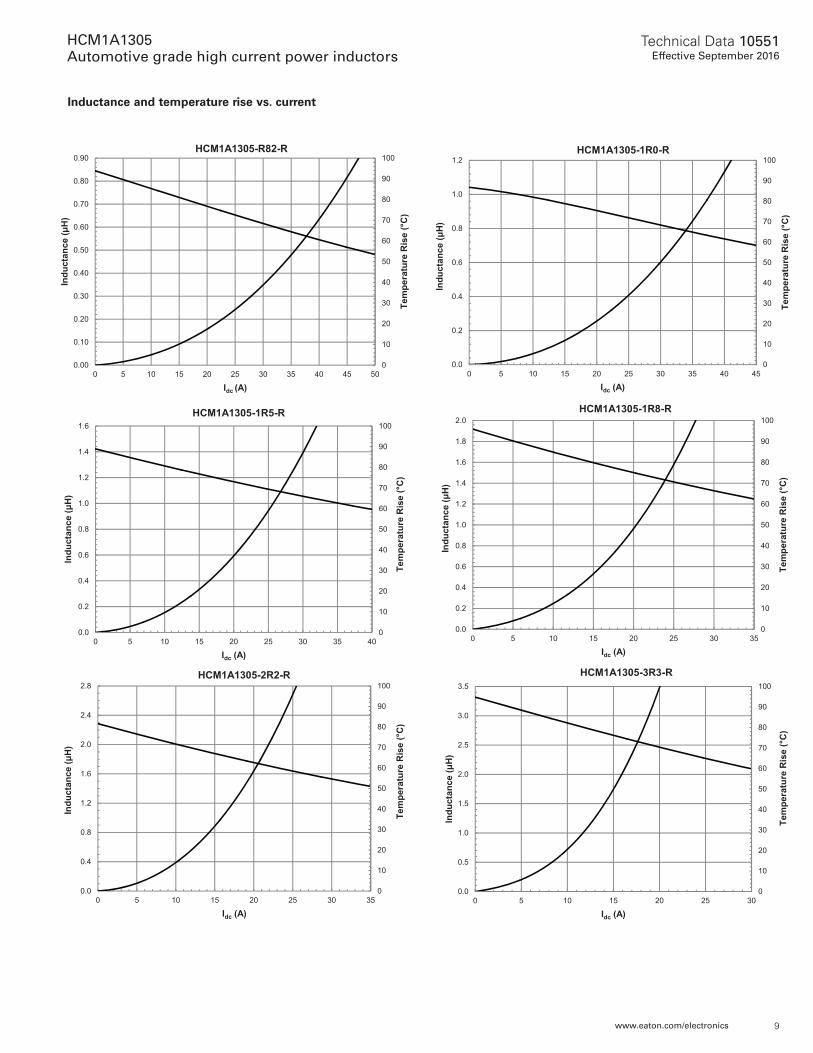
Inductance and temperature rise vs. current
0
10
20
30
40
50
60
70
80
90
100
0.00
0.10
0.20
0.30
0.40
0.50
0.60
0.70
0.80
0.90
0 5 10 15 20 25 30 35 40 45 50
Tem
pera
ture
Ris
e (°
C)
Indu
ctan
ce (μ
H)
Idc (A)
HCM1A1305-R82-R
0
10
20
30
40
50
60
70
80
90
100
0.0
0.2
0.4
0.6
0.8
1.0
1.2
0 5 10 15 20 25 30 35 40 45
Tem
pera
ture
Ris
e (°
C)
Indu
ctan
ce (μ
H)
Idc (A)
HCM1A1305-1R0-R
0
10
20
30
40
50
60
70
80
90
100
0.0
0.2
0.4
0.6
0.8
1.0
1.2
1.4
1.6
0 5 10 15 20 25 30 35 40
Tem
pera
ture
Ris
e (°
C)
Indu
ctan
ce (μ
H)
Idc (A)
HCM1A1305-1R5-R
0
10
20
30
40
50
60
70
80
90
100
0.0
0.2
0.4
0.6
0.8
1.0
1.2
1.4
1.6
1.8
2.0
0 5 10 15 20 25 30 35
Tem
pera
ture
Ris
e (°
C)
Indu
ctan
ce (μ
H)
Idc (A)
HCM1A1305-1R8-R
0
10
20
30
40
50
60
70
80
90
100
0.0
0.4
0.8
1.2
1.6
2.0
2.4
2.8
0 5 10 15 20 25 30 35
Tem
pera
ture
Ris
e (°
C)
Indu
ctan
ce (μ
H)
Idc (A)
HCM1A1305-2R2-R
0
10
20
30
40
50
60
70
80
90
100
0.0
0.5
1.0
1.5
2.0
2.5
3.0
3.5
0 5 10 15 20 25 30
Tem
pera
ture
Ris
e (°
C)
Indu
ctan
ce (μ
H)
Idc (A)
HCM1A1305-3R3-R
10
Technical Data 10551Effective September 2016
HCM1A1305Automotive grade high current power inductors
www.eaton.com/electronics
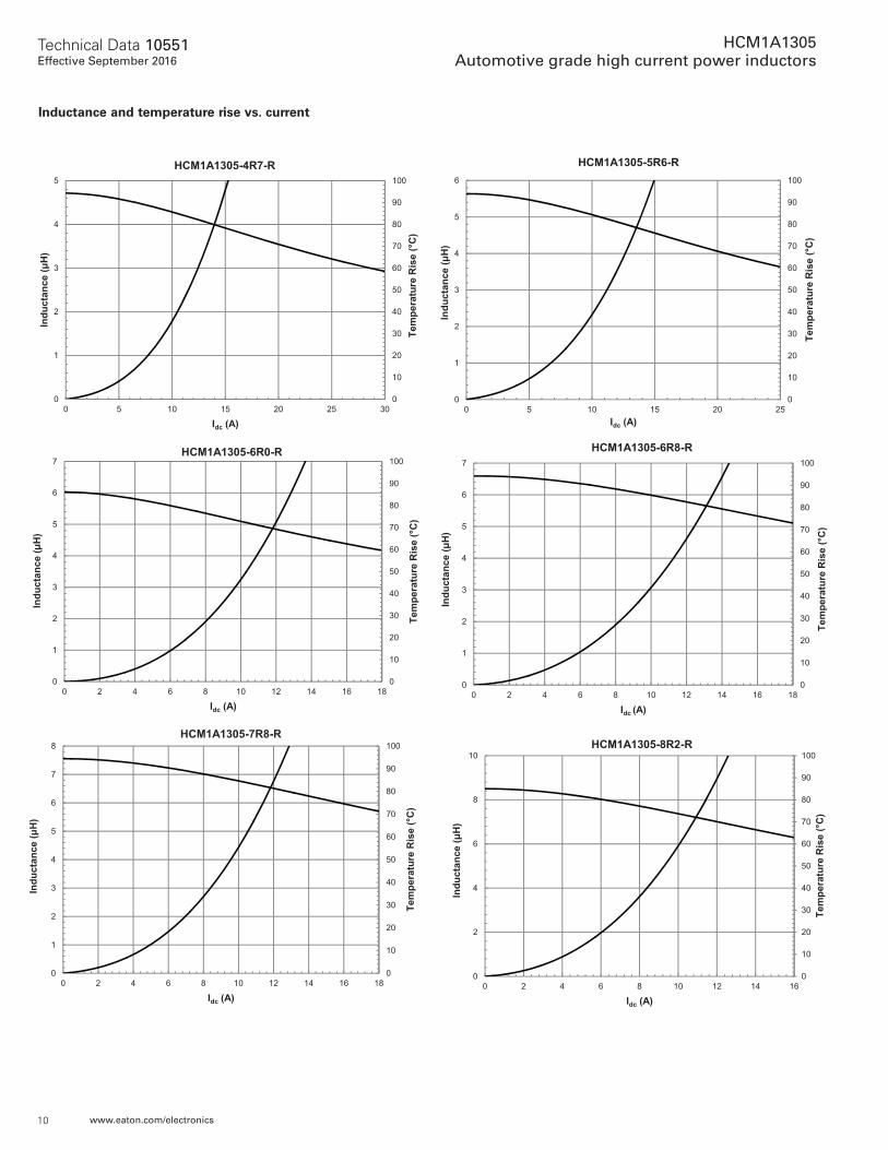
Inductance and temperature rise vs. current
0
10
20
30
40
50
60
70
80
90
100
0
1
2
3
4
5
0 5 10 15 20 25 30Te
mpe
ratu
re R
ise
(°C
)
Indu
ctan
ce (μ
H)
Idc (A)
HCM1A1305-4R7-R
0
10
20
30
40
50
60
70
80
90
100
0
1
2
3
4
5
6
0 5 10 15 20 25
Tem
pera
ture
Ris
e (°
C)
Indu
ctan
ce (μ
H)
Idc (A)
HCM1A1305-5R6-R
0
10
20
30
40
50
60
70
80
90
100
0
1
2
3
4
5
6
7
0 2 4 6 8 10 12 14 16 18
Tem
pera
ture
Ris
e (°
C)
Indu
ctan
ce (μ
H)
Idc (A)
HCM1A1305-6R0-R
0
10
20
30
40
50
60
70
80
90
100
0
1
2
3
4
5
6
7
0 2 4 6 8 10 12 14 16 18
Tem
pera
ture
Ris
e (°
C)
Indu
ctan
ce (μ
H)
Idc (A)
HCM1A1305-6R8-R
0
10
20
30
40
50
60
70
80
90
100
0
1
2
3
4
5
6
7
8
0 2 4 6 8 10 12 14 16 18
Tem
pera
ture
Ris
e (°
C)
Indu
ctan
ce (μ
H)
Idc (A)
HCM1A1305-7R8-R
0
10
20
30
40
50
60
70
80
90
100
0
2
4
6
8
10
0 2 4 6 8 10 12 14 16
Tem
pera
ture
Ris
e (°
C)
Indu
ctan
ce (μ
H)
Idc (A)
HCM1A1305-8R2-R
11
Technical Data 10551Effective September 2016
HCM1A1305Automotive grade high current power inductors
www.eaton.com/electronics
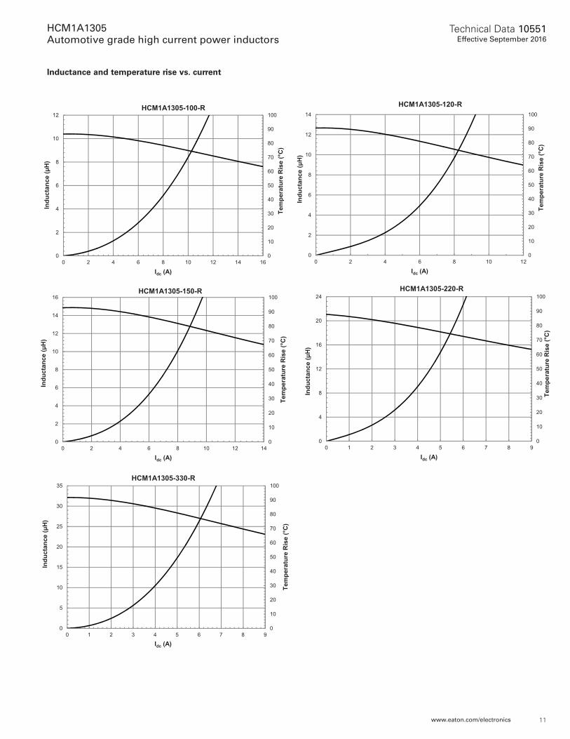
Inductance and temperature rise vs. current
0
10
20
30
40
50
60
70
80
90
100
0
2
4
6
8
10
12
0 2 4 6 8 10 12 14 16
Tem
pera
ture
Ris
e (°
C)
Indu
ctan
ce (μ
H)
Idc (A)
HCM1A1305-100-R
0
10
20
30
40
50
60
70
80
90
100
0
2
4
6
8
10
12
14
0 2 4 6 8 10 12
Tem
pera
ture
Ris
e (°
C)
Indu
ctan
ce (μ
H)
Idc (A)
HCM1A1305-120-R
0
10
20
30
40
50
60
70
80
90
100
0
2
4
6
8
10
12
14
16
0 2 4 6 8 10 12 14
Tem
pera
ture
Ris
e (°
C)
Indu
ctan
ce (μ
H)
Idc (A)
HCM1A1305-150-R
0
10
20
30
40
50
60
70
80
90
100
0
4
8
12
16
20
24
0 1 2 3 4 5 6 7 8 9
Tem
pera
ture
Ris
e (°
C)
Indu
ctan
ce (μ
H)
Idc (A)
HCM1A1305-220-R
0
10
20
30
40
50
60
70
80
90
100
0
5
10
15
20
25
30
35
0 1 2 3 4 5 6 7 8 9
Tem
pera
ture
Ris
e (°
C)
Indu
ctan
ce (μ
H)
Idc (A)
HCM1A1305-330-R
EatonElectronics Division1000 Eaton BoulevardCleveland, OH 44122United Stateswww.eaton.com/electronics
© 2016 EatonAll Rights ReservedPublication No. 10551 BU-MC16075September 2016
Eaton is a registered trademark.
All other trademarks are property of their respective owners.
Life Support Policy: Eaton does not authorize the use of any of its products for use in life support devices or systems without the express written approval of an officer of the Company. Life support systems are devices which support or sustain life, and whose failure to perform, when properly used in accordance with instructions for use provided in the labeling, can be reasonably expected to result in significant injury to the user.
Eaton reserves the right, without notice, to change design or construction of any products and to discontinue or limit distribution of any products. Eaton also reserves the right to change or update, without notice, any technical information contained in this bulletin.
Technical Data 10551Effective September 2016
HCM1A1305Automotive grade high current power inductors
Tem
pera
ture
t
tP
ts
TC -5°C
Time 25°C to Peak Time25°C
Tsmin
Tsmax
TL
TP
PreheatA
Max. Ramp Up Rate = 3°C/sMax. Ramp Down Rate = 6°C/s
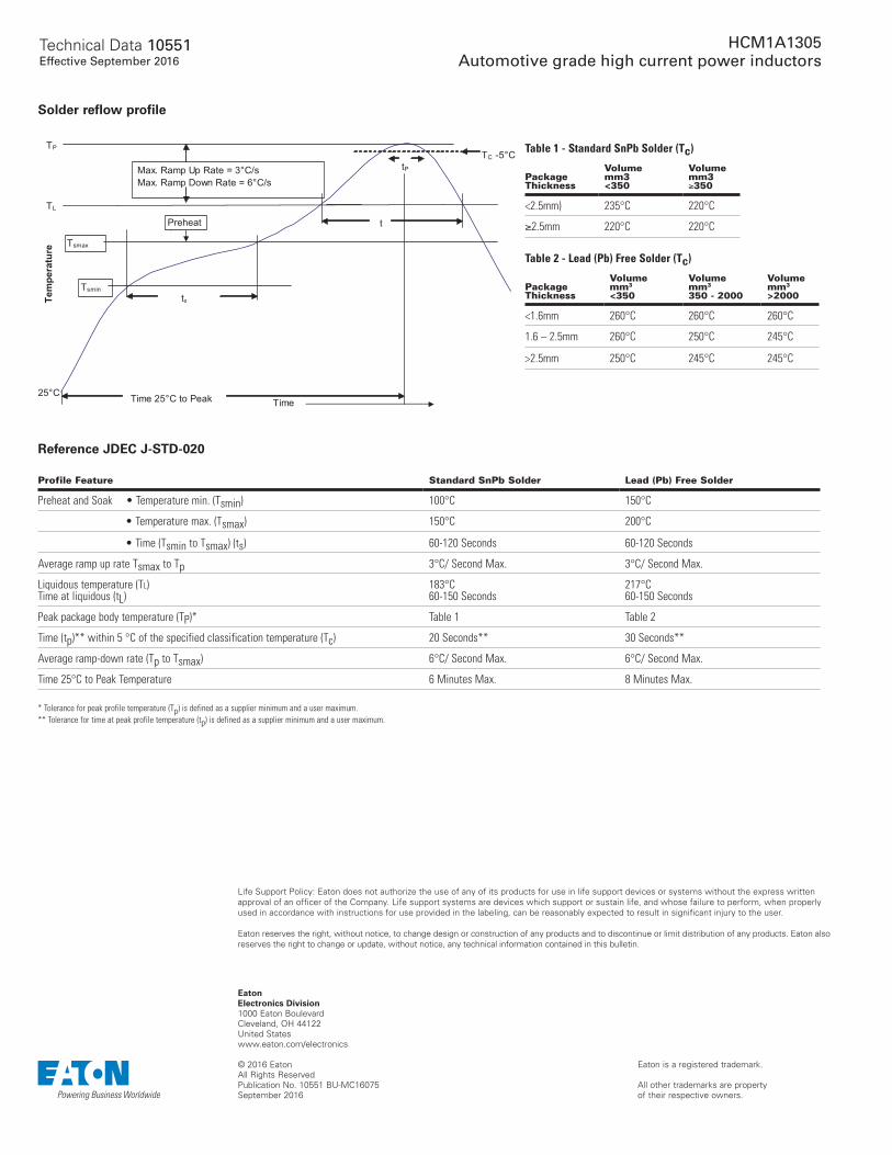
Solder reflow profile
Reference JDEC J-STD-020
Profile Feature Standard SnPb Solder Lead (Pb) Free Solder
Preheat and Soak • Temperature min. (Tsmin) 100°C 150°C
• Temperature max. (Tsmax) 150°C 200°C
• Time (Tsmin to Tsmax) (ts) 60-120 Seconds 60-120 Seconds
Average ramp up rate Tsmax to Tp 3°C/ Second Max. 3°C/ Second Max.
Liquidous temperature (Tl) Time at liquidous (tL)
183°C 60-150 Seconds
217°C 60-150 Seconds
Peak package body temperature (TP)* Table 1 Table 2
Time (tp)** within 5 °C of the specified classification temperature (Tc) 20 Seconds** 30 Seconds**
Average ramp-down rate (Tp to Tsmax) 6°C/ Second Max. 6°C/ Second Max.
Time 25°C to Peak Temperature 6 Minutes Max. 8 Minutes Max. * Tolerance for peak profile temperature (Tp) is defined as a supplier minimum and a user maximum.** Tolerance for time at peak profile temperature (tp) is defined as a supplier minimum and a user maximum.
Table 1 - Standard SnPb Solder (Tc)
Package Thickness
Volume mm3 <350
Volume mm3 ≥350
<2.5mm) 235°C 220°C
≥2.5mm 220°C 220°C
Table 2 - Lead (Pb) Free Solder (Tc)
Package Thickness
Volume mm3 <350
Volume mm3 350 - 2000
Volume mm3 >2000
<1.6mm 260°C 260°C 260°C
1.6 – 2.5mm 260°C 250°C 245°C
>2.5mm 250°C 245°C 245°C


![B C H B F P F U : ] $POUBDU XXX BUIFOTWJEFPBSUGFTUJWBM … · Κωνσταντίνος Καβάφης (∆7) και Κώστας Βάρναλης (Α8). Σύµβολο της το](https://static.fdocument.org/doc/165x107/5e472a07b68e936fc83a4dea/b-c-h-b-f-p-f-u-poubdu-xxx-buifotwjefpbsugftujwbm-f.jpg)