Artist Friendly Metallic Fresnel
9
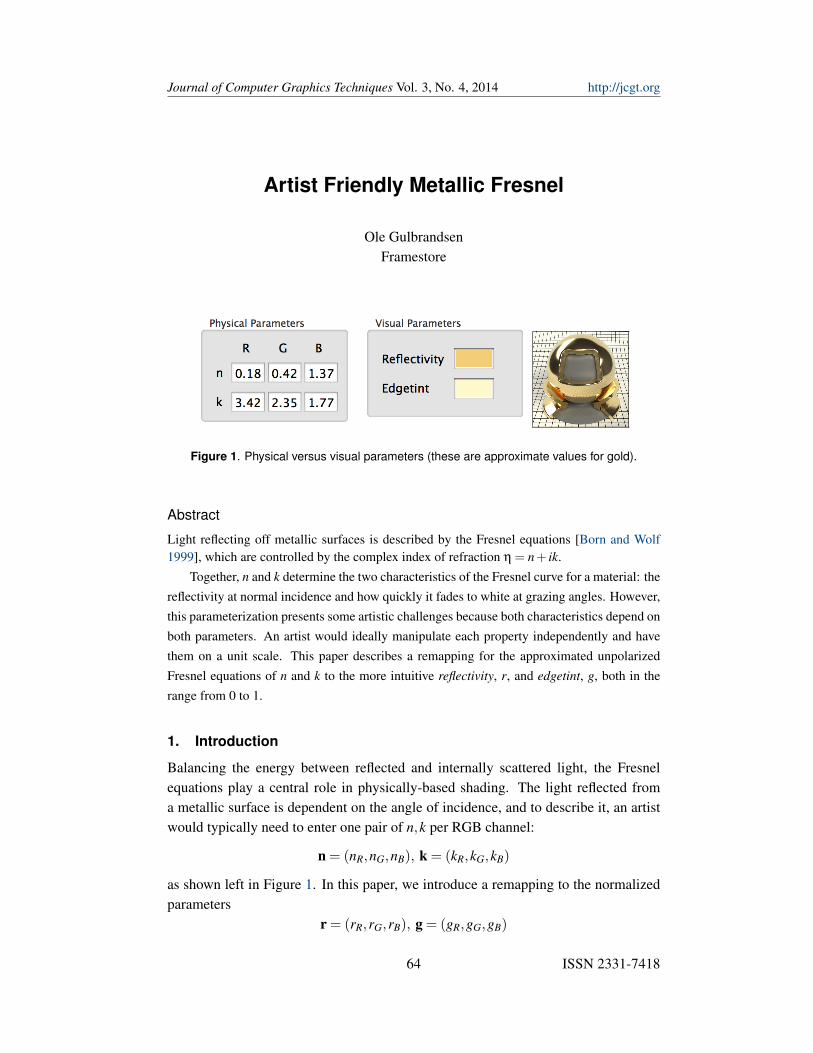
Journal of Computer Graphics Techniques Vol. 3, No. 4, 2014 http://jcgt.org Artist Friendly Metallic Fresnel Ole Gulbrandsen Framestore Figure 1. Physical versus visual parameters (these are approximate values for gold). Abstract Light reflecting off metallic surfaces is described by the Fresnel equations [Born and Wolf 1999], which are controlled by the complex index of refraction η = n + ik. Together, n and k determine the two characteristics of the Fresnel curve for a material: the reflectivity at normal incidence and how quickly it fades to white at grazing angles. However, this parameterization presents some artistic challenges because both characteristics depend on both parameters. An artist would ideally manipulate each property independently and have them on a unit scale. This paper describes a remapping for the approximated unpolarized Fresnel equations of n and k to the more intuitive reflectivity, r, and edgetint, g, both in the range from 0 to 1. 1. Introduction Balancing the energy between reflected and internally scattered light, the Fresnel equations play a central role in physically-based shading. The light reflected from a metallic surface is dependent on the angle of incidence, and to describe it, an artist would typically need to enter one pair of n, k per RGB channel: n =(n R , n G , n B ), k =(k R , k G , k B ) as shown left in Figure 1. In this paper, we introduce a remapping to the normalized parameters r =(r R , r G , r B ), g =(g R , g G , g B ) 64 ISSN 2331-7418
Transcript of Artist Friendly Metallic Fresnel
Journal of Computer Graphics Techniques Vol. 3, No. 4, 2014 http://jcgt.org
Artist Friendly Metallic Fresnel
Ole GulbrandsenFramestore
Figure 1. Physical versus visual parameters (these are approximate values for gold).
Abstract
Light reflecting off metallic surfaces is described by the Fresnel equations [Born and Wolf1999], which are controlled by the complex index of refraction η = n+ ik.
Together, n and k determine the two characteristics of the Fresnel curve for a material: thereflectivity at normal incidence and how quickly it fades to white at grazing angles. However,this parameterization presents some artistic challenges because both characteristics depend onboth parameters. An artist would ideally manipulate each property independently and havethem on a unit scale. This paper describes a remapping for the approximated unpolarizedFresnel equations of n and k to the more intuitive reflectivity, r, and edgetint, g, both in therange from 0 to 1.
1. Introduction
Balancing the energy between reflected and internally scattered light, the Fresnelequations play a central role in physically-based shading. The light reflected froma metallic surface is dependent on the angle of incidence, and to describe it, an artistwould typically need to enter one pair of n,k per RGB channel:
n = (nR,nG,nB), k = (kR,kG,kB)
as shown left in Figure 1. In this paper, we introduce a remapping to the normalizedparameters
r = (rR,rG,rB), g = (gR,gG,gB)
64 ISSN 2331-7418
Journal of Computer Graphics TechniquesArtist Friendly Metallic Fresnel
Vol. 3, No. 4, 2014http://jcgt.org
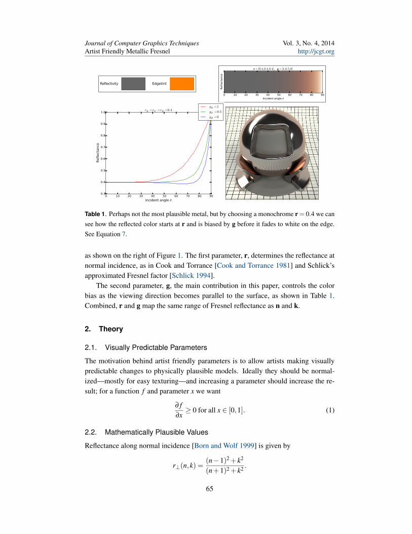
Reflectivity Edgetint
0 10 20 30 40 50 60 70 80 90Incident angle θ
Reflect
ance
r =[0.4,0.4,0.4], g =[1,0.5,0]
0 10 20 30 40 50 60 70 80 90
Incident angle θ
0.3
0.4
0.5
0.6
0.7
0.8
0.9
1.0
Reflect
ance
rR =rG =rB =0.4gR =1
gG =0.5
gB =0
Table 1. Perhaps not the most plausible metal, but by choosing a monochrome r = 0.4 we cansee how the reflected color starts at r and is biased by g before it fades to white on the edge.See Equation 7.
as shown on the right of Figure 1. The first parameter, r, determines the reflectance atnormal incidence, as in Cook and Torrance [Cook and Torrance 1981] and Schlick’sapproximated Fresnel factor [Schlick 1994].
The second parameter, g, the main contribution in this paper, controls the colorbias as the viewing direction becomes parallel to the surface, as shown in Table 1.Combined, r and g map the same range of Fresnel reflectance as n and k.
2. Theory
2.1. Visually Predictable Parameters
The motivation behind artist friendly parameters is to allow artists making visuallypredictable changes to physically plausible models. Ideally they should be normal-ized—mostly for easy texturing—and increasing a parameter should increase the re-sult; for a function f and parameter x we want
∂ f∂x≥ 0 for all x ∈ [0,1]. (1)
2.2. Mathematically Plausible Values
Reflectance along normal incidence [Born and Wolf 1999] is given by
r⊥(n,k) =(n−1)2 + k2
(n+1)2 + k2 .
65
Journal of Computer Graphics TechniquesArtist Friendly Metallic Fresnel
Vol. 3, No. 4, 2014http://jcgt.org
0 2 4 6 8 10 12
n
0
1
2
3
4
5
6
k
r=0.5
r=0.6
r=0.7
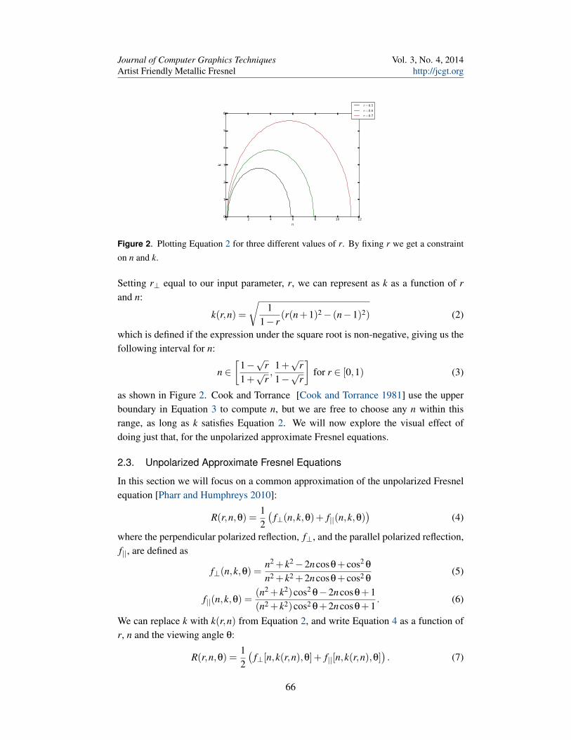
Figure 2. Plotting Equation 2 for three different values of r. By fixing r we get a constrainton n and k.
Setting r⊥ equal to our input parameter, r, we can represent as k as a function of rand n:
k(r,n) =
√1
1− r(r(n+1)2− (n−1)2) (2)
which is defined if the expression under the square root is non-negative, giving us thefollowing interval for n:
n ∈[
1−√
r1+√
r,1+√
r1−√
r
]for r ∈ [0,1) (3)
as shown in Figure 2. Cook and Torrance [Cook and Torrance 1981] use the upperboundary in Equation 3 to compute n, but we are free to choose any n within thisrange, as long as k satisfies Equation 2. We will now explore the visual effect ofdoing just that, for the unpolarized approximate Fresnel equations.
2.3. Unpolarized Approximate Fresnel Equations
In this section we will focus on a common approximation of the unpolarized Fresnelequation [Pharr and Humphreys 2010]:
R(r,n,θ) =12(
f⊥(n,k,θ)+ f||(n,k,θ))
(4)
where the perpendicular polarized reflection, f⊥, and the parallel polarized reflection,f||, are defined as
f⊥(n,k,θ) =n2 + k2−2ncosθ+ cos2 θ
n2 + k2 +2ncosθ+ cos2 θ(5)
f||(n,k,θ) =(n2 + k2)cos2 θ−2ncosθ+1(n2 + k2)cos2 θ+2ncosθ+1
. (6)
We can replace k with k(r,n) from Equation 2, and write Equation 4 as a function ofr, n and the viewing angle θ:
R(r,n,θ) =12(
f⊥[n,k(r,n),θ]+ f||[n,k(r,n),θ]). (7)
66
Journal of Computer Graphics TechniquesArtist Friendly Metallic Fresnel
Vol. 3, No. 4, 2014http://jcgt.org
2.3.1. Reflectivity and Edgetint
We want R to be monotonically increasing (Equation 1) with respect to both r and g.Starting with r; since we defined r as the reflectivity at normal incidence, we onlyneed to show that
∂R∂r≥ 0
for θ = 0, which is trivial, since
R(r,n,0) = r.
Hence r is a valid parameter. The next challenge is finding g. The idea is using g tointerpolate between the valid values of n. We can show that
∂R∂n
= 0 (8)
forn = 0 and n =
1− r1+ r
(9)
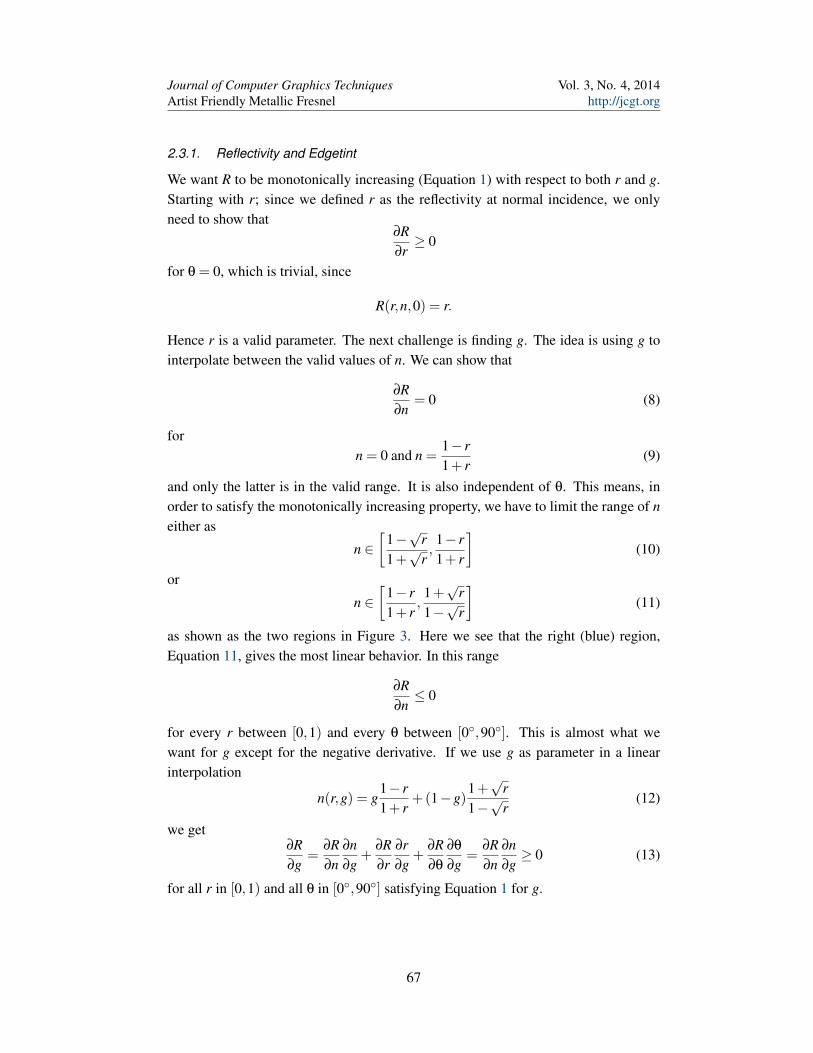
and only the latter is in the valid range. It is also independent of θ. This means, inorder to satisfy the monotonically increasing property, we have to limit the range of neither as
n ∈[
1−√
r1+√
r,1− r1+ r
](10)
or
n ∈[
1− r1+ r
,1+√
r1−√
r
](11)
as shown as the two regions in Figure 3. Here we see that the right (blue) region,Equation 11, gives the most linear behavior. In this range
∂R∂n≤ 0
for every r between [0,1) and every θ between [0◦,90◦]. This is almost what wewant for g except for the negative derivative. If we use g as parameter in a linearinterpolation
n(r,g) = g1− r1+ r
+(1−g)1+√
r1−√
r(12)
we get∂R∂g
=∂R∂n
∂n∂g
+∂R∂r
∂r∂g
+∂R∂θ
∂θ
∂g=
∂R∂n
∂n∂g≥ 0 (13)
for all r in [0,1) and all θ in [0◦,90◦] satisfying Equation 1 for g.
67
Journal of Computer Graphics TechniquesArtist Friendly Metallic Fresnel
Vol. 3, No. 4, 2014http://jcgt.org
0.0 0.5 1.0 1.5 2.0 2.5 3.0
n
0.205
0.210
0.215
0.220
0.225
0.230
R(0.2,n,π 4
)
n= 1−r1 +r
n= 1−√r
1 +√r
n=1 +√r
1−√r
r=0.2,θ=π/4
Figure 3. Plotting R as a function of n. We can use either the left or the right side, since R isthe same at n = 1−
√r
1+√
r and n = 1+√
r1−√
r .
2.3.2. Invertibility
Finally we want to make sure that for each (n,k) there is a unique (r,g) and vice versa.Since we have the inverse mapping
r(n,k) =(n−1)2 + k2
(n+1)2 + k2 (14)
and
g(n,k) =
1+√
r(n,k)
1−√
r(n,k)−n
1+√
r(n,k)
1−√
r(n,k)− 1−r(n,k)
1+r(n,k)
(15)
and the determinant of the Jacobian∣∣∣∣∣∂n∂r
∂n∂g
∂k∂r
∂k∂g
∣∣∣∣∣> 0
for all r,g ∈ (0,1), the map from (n,k) to (r,g) is a bijection.
2.3.3. Final Parameters
For the approximated Fresnel equations, we have the following remapping
n(r,g) = g1− r1+ r
+(1−g)1+√
r1−√
r
k(r,n(r,g)) =
√1
1− r(r(n(r,g)+1)2− (n(r,g)−1)2)
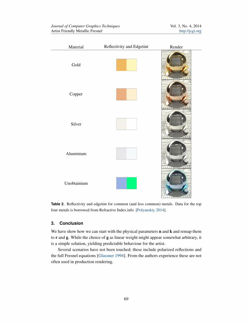
where r ∈ [0,1) and g ∈ [0,1]. Table 2 shows a list of common materials and theirreflectivity/edgetint parameters.
68
Journal of Computer Graphics TechniquesArtist Friendly Metallic Fresnel
Vol. 3, No. 4, 2014http://jcgt.org
Material Reflectivity and Edgetint Render
Gold
Copper
Silver
Aluminium
Unobtainium
Table 2. Reflectivity and edgetint for common (and less common) metals. Data for the topfour metals is borrowed from Refractive Index.info [Polyanskiy 2014].
3. Conclusion
We have show how we can start with the physical parameters n and k and remap themto r and g. While the choice of g as linear weight might appear somewhat arbitrary, itis a simple solution, yielding predictable behaviour for the artist.
Several scenarios have not been touched; these include polarized reflections andthe full Fresnel equations [Glassner 1994]. From the authors experience these are notoften used in production rendering.
69
Journal of Computer Graphics TechniquesArtist Friendly Metallic Fresnel
Vol. 3, No. 4, 2014http://jcgt.org
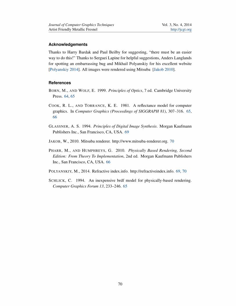
Acknowledgements
Thanks to Harry Bardak and Paul Beilby for suggesting, “there must be an easierway to do this!” Thanks to Serguei Lapine for helpful suggestions, Anders Langlandsfor spotting an embarrassing bug and Mikhail Polyanskiy for his excellent website[Polyanskiy 2014]. All images were rendered using Mitsuba [Jakob 2010].
References
BORN, M., AND WOLF, E. 1999. Principles of Optics, 7 ed. Cambridge UniversityPress. 64, 65
COOK, R. L., AND TORRANCE, K. E. 1981. A reflectance model for computergraphics. In Computer Graphics (Proceedings of SIGGRAPH 81), 307–316. 65,66
GLASSNER, A. S. 1994. Principles of Digital Image Synthesis. Morgan KaufmannPublishers Inc., San Francisco, CA, USA. 69
JAKOB, W., 2010. Mitsuba renderer. http://www.mitsuba-renderer.org. 70
PHARR, M., AND HUMPHREYS, G. 2010. Physically Based Rendering, SecondEdition: From Theory To Implementation, 2nd ed. Morgan Kaufmann PublishersInc., San Francisco, CA, USA. 66
POLYANSKIY, M., 2014. Refractive index.info. http://refractiveindex.info. 69, 70
SCHLICK, C. 1994. An inexpensive brdf model for physically-based rendering.Computer Graphics Forum 13, 233–246. 65
70
Journal of Computer Graphics TechniquesArtist Friendly Metallic Fresnel
Vol. 3, No. 4, 2014http://jcgt.org
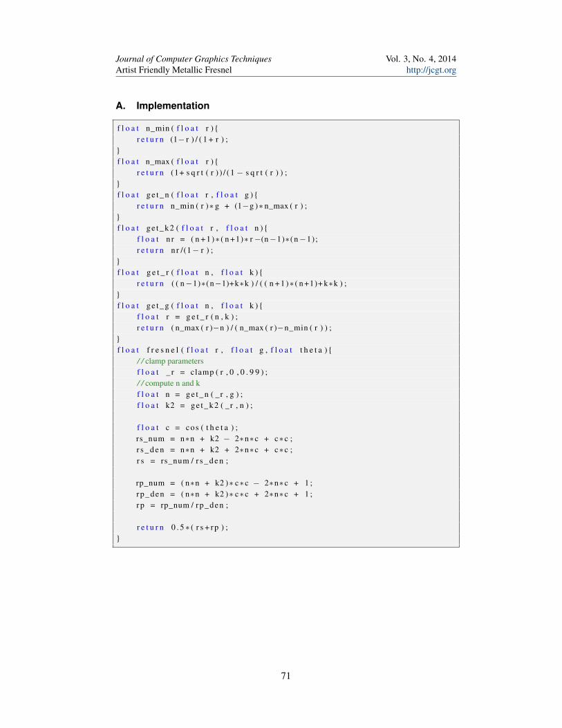
A. Implementation
f l o a t n_min ( f l o a t r ) {r e t u r n (1− r ) / ( 1 + r ) ;
}f l o a t n_max ( f l o a t r ) {
r e t u r n (1+ s q r t ( r ) ) / ( 1 − s q r t ( r ) ) ;}f l o a t g e t _ n ( f l o a t r , f l o a t g ) {
r e t u r n n_min ( r )∗ g + (1−g )∗ n_max ( r ) ;}f l o a t ge t_ k2 ( f l o a t r , f l o a t n ) {
f l o a t n r = ( n + 1 )∗ ( n +1)∗ r −(n−1)∗(n−1);r e t u r n n r /(1− r ) ;
}f l o a t g e t _ r ( f l o a t n , f l o a t k ) {
r e t u r n ( ( n−1)∗(n−1)+k∗k ) / ( ( n + 1 )∗ ( n +1)+ k∗k ) ;}f l o a t g e t _ g ( f l o a t n , f l o a t k ) {
f l o a t r = g e t _ r ( n , k ) ;r e t u r n ( n_max ( r )−n ) / ( n_max ( r )−n_min ( r ) ) ;
}f l o a t f r e s n e l ( f l o a t r , f l o a t g , f l o a t t h e t a ) {
/ / clamp parametersf l o a t _ r = clamp ( r , 0 , 0 . 9 9 ) ;/ / compute n and kf l o a t n = g e t _ n ( _r , g ) ;f l o a t k2 = ge t_ k2 ( _r , n ) ;
f l o a t c = cos ( t h e t a ) ;rs_num = n∗n + k2 − 2∗n∗c + c∗c ;r s _ d e n = n∗n + k2 + 2∗n∗c + c∗c ;r s = rs_num / r s _ d e n ;
rp_num = ( n∗n + k2 )∗ c∗c − 2∗n∗c + 1 ;rp_den = ( n∗n + k2 )∗ c∗c + 2∗n∗c + 1 ;rp = rp_num / rp_den ;
r e t u r n 0 . 5∗ ( r s + rp ) ;}
71
Journal of Computer Graphics TechniquesArtist Friendly Metallic Fresnel
Vol. 3, No. 4, 2014http://jcgt.org
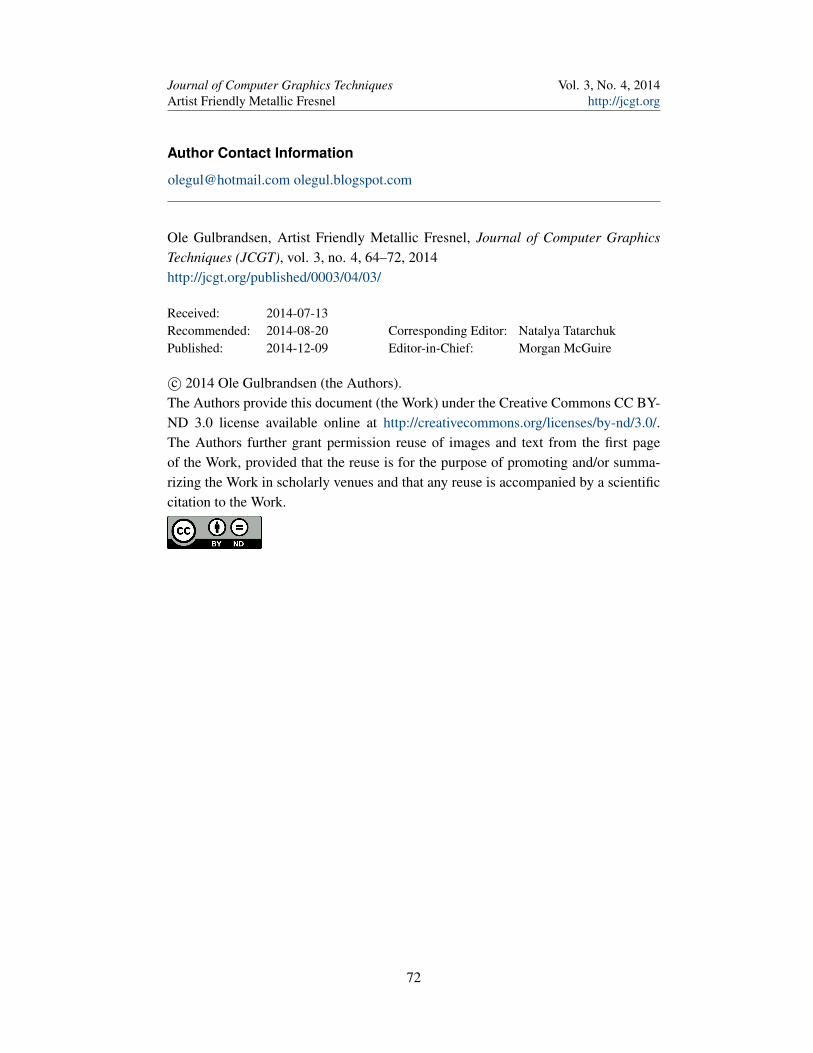
Author Contact Information
[email protected] olegul.blogspot.com
Ole Gulbrandsen, Artist Friendly Metallic Fresnel, Journal of Computer GraphicsTechniques (JCGT), vol. 3, no. 4, 64–72, 2014http://jcgt.org/published/0003/04/03/
Received: 2014-07-13Recommended: 2014-08-20 Corresponding Editor: Natalya TatarchukPublished: 2014-12-09 Editor-in-Chief: Morgan McGuire
c© 2014 Ole Gulbrandsen (the Authors).The Authors provide this document (the Work) under the Creative Commons CC BY-ND 3.0 license available online at http://creativecommons.org/licenses/by-nd/3.0/.The Authors further grant permission reuse of images and text from the first pageof the Work, provided that the reuse is for the purpose of promoting and/or summa-rizing the Work in scholarly venues and that any reuse is accompanied by a scientificcitation to the Work.
72