Huygens principle; young interferometer; Fresnel diffraction · 2019-08-15 · Phase delay from a...
26
Today • Interference – inadequacy of a single intensity measurement to determine the optical field – Michelson interferometer • measuring – distance – index of refraction – Mach-Zehnder interferometer • measuring – wavefront MIT 2.71/2.710 03/30/09 wk8-a- 1
Transcript of Huygens principle; young interferometer; Fresnel diffraction · 2019-08-15 · Phase delay from a...
Today
• Interference – inadequacy of a single intensity measurement to determine the
optical field – Michelson interferometer
• measuring – distance – index of refraction
– Mach-Zehnder interferometer • measuring
– wavefront
MIT 2.71/2.710 03/30/09 wk8-a- 1
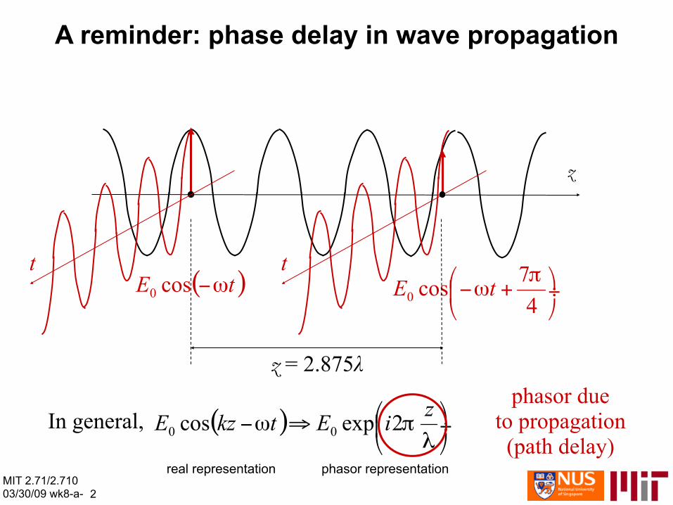
A reminder: phase delay in wave propagation
z
t
z = 2.875λ
t
phasor due In general, to propagation
(path delay)real representation phasor representation
MIT 2.71/2.710 03/30/09 wk8-a- 2
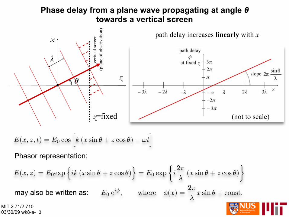
Phase delay from a plane wave propagating at angle θtowards a vertical screen
path delay increases linearly with x
verti
cal s
cree
n(p
lane
of o
bser
vatio
n)
z=fixed
x
θ z
λ
(not to scale)
Phasor representation:
MIT 2.71/2.710 03/30/09 wk8-a- 3
may also be written as:
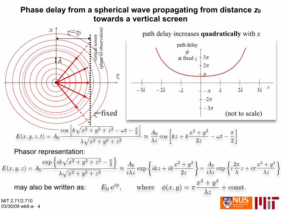
Phase delay from a spherical wave propagating from distance z0
towards a vertical screen
MIT 2.71/2.710 03/30/09 wk8-a- 4
path delay increases quadratically with x
Phasor representation:
may also be written as:
x
z
λ verti
cal s
cree
n(p
lane
of o
bser
vatio
n)
z=fixed
z=z0
(not to scale)

The significance of phase delays
• The intensity of plane and spherical waves, observed on a screen, is very similar so they cannot be reliably discriminated – note that the 1/(x2+y2+z2) intensity variation in the case of the
spherical wave is too weak in the paraxial case z>>|x|, |y| so in practice it cannot be measured reliably
• In many other cases, the phase of the field carries important information, for example
– the “history” of where the field has been through • distance traveled • materials in the path • generally, the “optical path length” is inscribed in the phase
– the evolution of the field beyond its present position (“diffraction”) • However, phase cannot be measured directly (e.g., with an oscillo-
scope, because the optical field varies too rapidly, f~1014-1015 Hz • Interferometry measures the phase by comparing two fields: the
unknown, or “signal” field with a known “reference” field MIT 2.71/2.710 03/30/09 wk8-a- 5

Michelson interferometer
reference mirror
signal mirror
unknown object or path
light source
lens
photo-detector
refe
renc
ear
m
signal arm
beam splitter
where Ar, As are the amplitudes and φr, φs the phase delaysintroduced after one round trip
in the reference and signal arms, respectively
The photo-detector receives the field sum of the waves arriving from the reference and signal arms:
wave fromsignal arm t
wave fromreference arm + =
t
t
reference and signal waves in phase: constructive interference
wave fromsignal arm t
wave from reference arm + =
t
t
reference and signal waves out of phase:destructive interference
MIT 2.71/2.710 03/30/09 wk8-a- 6
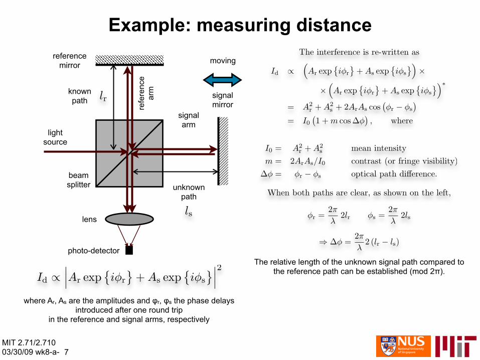
Example: measuring distance reference movingmirror
refe
renc
ear
m
The relative length of the unknown signal path compared to the reference path can be established (mod 2π).
known signalpath mirror
signal arm
light source
beamsplitter unknown
path
lens
photo-detector
where Ar, As are the amplitudes and φr, φs the phase delaysintroduced after one round trip
in the reference and signal arms, respectively
MIT 2.71/2.710 03/30/09 wk8-a- 7
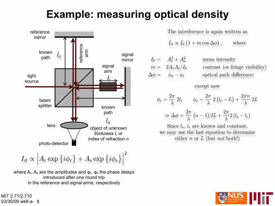
Example: measuring optical density
reference mirror
signal mirror
known path
beam splitter
light source
lens
refe
renc
ear
m
signal arm
known path
object of unknown thickness L or
index of refraction n photo-detector
where Ar, As are the amplitudes and φr, φs the phase delaysintroduced after one round trip
in the reference and signal arms, respectively
MIT 2.71/2.710 03/30/09 wk8-a- 8
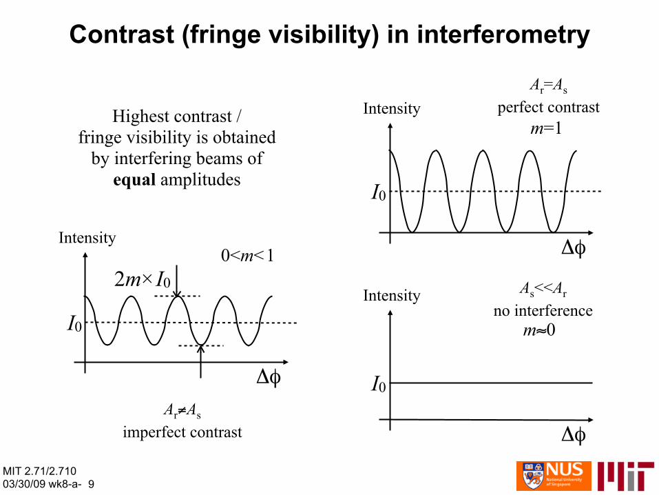
Contrast (fringe visibility) in interferometry
Ar=As
Highest contrast / Intensity perfect contrast
fringe visibility is obtained m=1
by interfering beams of equal amplitudes Ι0
Intensity 0<m<1 Δφ
2m×Ι0 A <<As rIntensity no interferenceΙ0 m≈0
Δφ Ι0 Ar≠As
imperfect contrast Δφ
MIT 2.71/2.710 03/30/09 wk8-a- 9
2.71/2.710/30/09 wk8-a-10
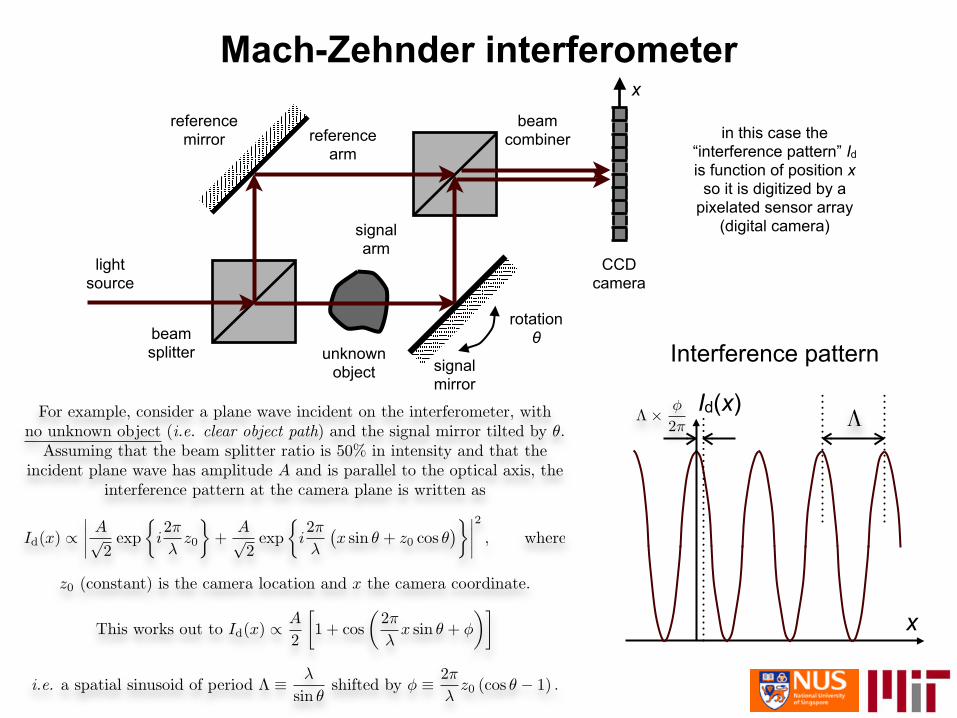
Mach-Zehnder interferometerx
Interference pattern
reference beam mirror
signal mirror
unknown object
light source
reference arm
signal arm
beam splitter
combiner
rotation θ
CCD camera
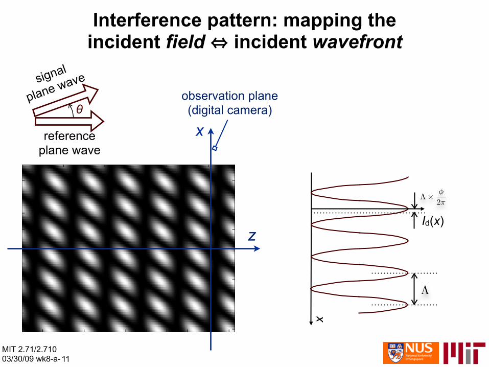
in this case the “interference pattern” Ιd is function of position x
so it is digitized by a pixelated sensor array
(digital camera)
MIT 03
x
Id(x)
signal
Interference pattern: mapping the incident field ⇔ incident wavefront
θplane wave
observation plane(digital camera)
MIT 2.71/2.710 03/30/09 wk8-a-11
xreference plane wave
z
x
Id(x)

Today
• Huygens principle • Young’s interferometer • Generalizing Young’s interferometer:
Huygens principle and thin transparencies ⇒
⇒ Fresnel diffraction integral
• Diffraction – Fresnel regime
Next week
– Fraunhofer regime • Spatial frequencies and Fourier transforms • Fraunhofer patterns of typical apertures
MIT 2.71/2.710 04/01/09 wk8-b- 1

Huygens principle
optical wavefront
Each point on the wavefront acts as a secondary light source emitting a spherical wave
The wavefront after a short propagation distance is the result of superimposing all these spherical waves, i.e. adding the corresponding phasors including the phase delay incurred due to propagation
MIT 2.71/2.710 04/01/09 wk8-b- 2

Example: hole in an opaque screen
x=x0
sphericalwave
incoming z =lplane wave opaque
(on-axis) screen
MIT 2.71/2.710 04/01/09 wk8-b- 3
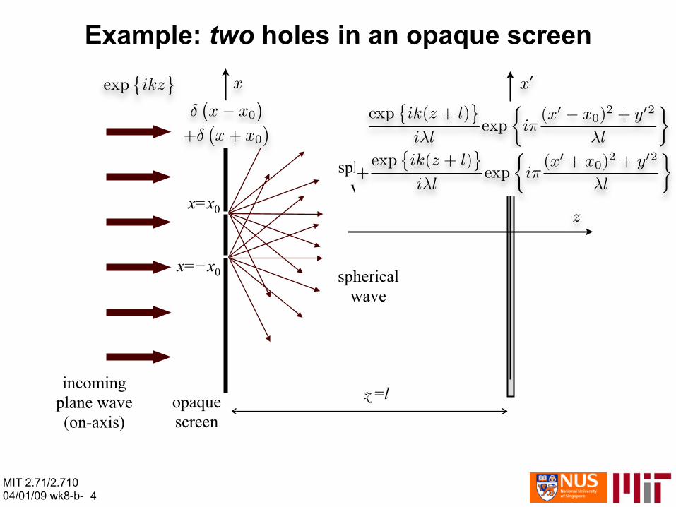
Example: two holes in an opaque screen
incoming plane wave opaque z =l
x=x0
spherical wave
spherical wave
x=−x0
(on-axis) screen
MIT 2.71/2.710 04/01/09 wk8-b- 4
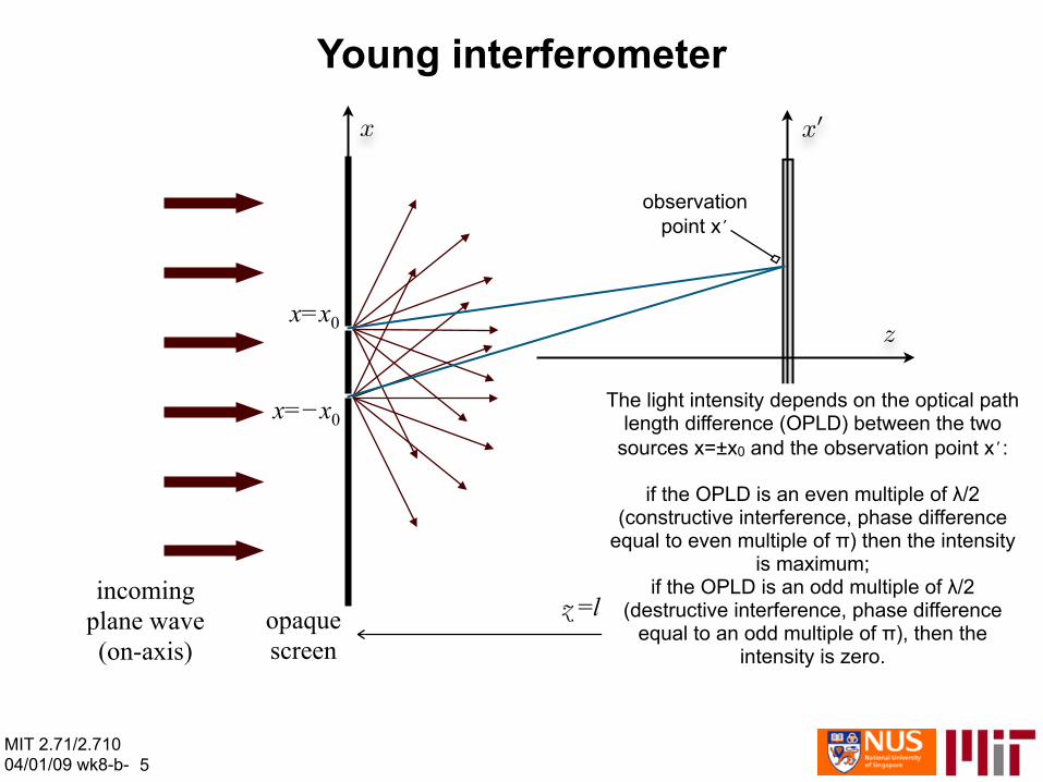
Young interferometer
x=x0
x=−x0
incoming plane wave opaque (on-axis) screen
z =l
The light intensity depends on the optical path length difference (OPLD) between the two
sources x=±x0 and the observation point x’:
if the OPLD is an even multiple of λ/2 (constructive interference, phase difference
equal to even multiple of π) then the intensity is maximum;
if the OPLD is an odd multiple of λ/2 (destructive interference, phase difference
equal to an odd multiple of π), then the intensity is zero.
observationpoint x’
MIT 2.71/2.710 04/01/09 wk8-b- 5
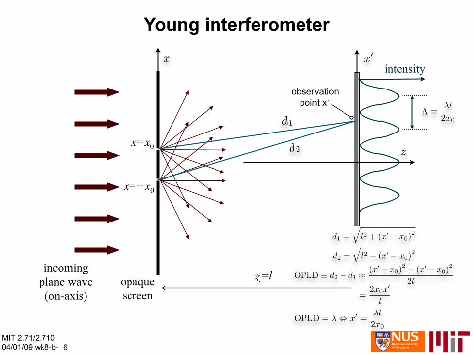
Young interferometer
x=x0
x=−x0
incoming plane wave opaque (on-axis) screen
z =l
observationpoint x’
intensity
MIT 2.71/2.710 04/01/09 wk8-b- 6

Derivation of Young’s interference pattern
inte
nsity
MIT 2.71/2.710 04/01/09 wk8-b- 7

Thin transparencyincident transmitted
wavefront wavefront
>~λ
<~50λ
Assumptions: ➡ features on the transparency are larger than ~λ ➡ thickness of the transparency may be neglected
The transparency has two effects on the incoming wavefront: ‣ attenuation, which is determined by the opacity of the transparency at a given location, and typically is
‣ binary (more common; transmission is either completely clear or completely opaque) or ‣ grayscale (at greater expense)
‣ phase delay, which is dependent on the optical path length (OPL) at the transmissive (or grayscale) locations, and is
‣ binary (more common; phase delay is one of two values); ‣ multi-level (at greater expense; phase delay is one of M values); or ‣ continuous (also known as surface relief)
The attenuation and phase delay imposed by the thin transparency are described together as a complex transmission function, whose ‣ modulus is the attenuation; and ‣ phase is the phase delay
MIT 2.71/2.710 04/01/09 wk8-b- 8

Thin transparency: generalized Young interferometerincident
wavefront,decomposed
intoHuygens
point sources
transmitted The thin transparency may also be thought of as awavefront, generalized Young’s interferometer in the following sense:
decomposed We decompose the incident wavefront into Huygens point into
sources; Huygens principle says that the transmittedHuygens wavefront may also be decomposed into point sources.point sources
If the transparency is sufficiently thin, the each Huygens point source in the incident wavefront is directly transmitted
to a Huygens point source in the outgoing wavefront, possibly with an attenuation and phase delay given by the
transparency’s complex transmission function.
The overall transmitted wavefront is the superposition of the Huygens point sources obtained by point-by-point
multiplication of the incident wavefront times the complex transmission function. Therefore, the overall transmitted
wavefront is obtained as a generalized Young’s interferometer with not just two, but a continuum of (infinite)
point sources.
Using the sifting property of delta functions we can express the incident and transmitted wavefronts as
MIT 2.71/2.710 04/01/09 wk8-b- 9

The Fresnel diffraction integralincident
wavefront, decomposed
into Huygens
point sources
transmitted wavefront, decomposed
into Huygens
point sources Each Huygens point source is a divergent spherical wave; therefore, after propagating by distance z in free space, it can be expressed as
The entire propagated wavefront is the superposition of the propagated Huygens point sources at the wavefront transmitted by the transparency, so it may be expressed as
This result is known asFresnel diffraction integral
(or simply Fresnel integral)
MIT 2.71/2.710 04/01/09 wk8-b-10
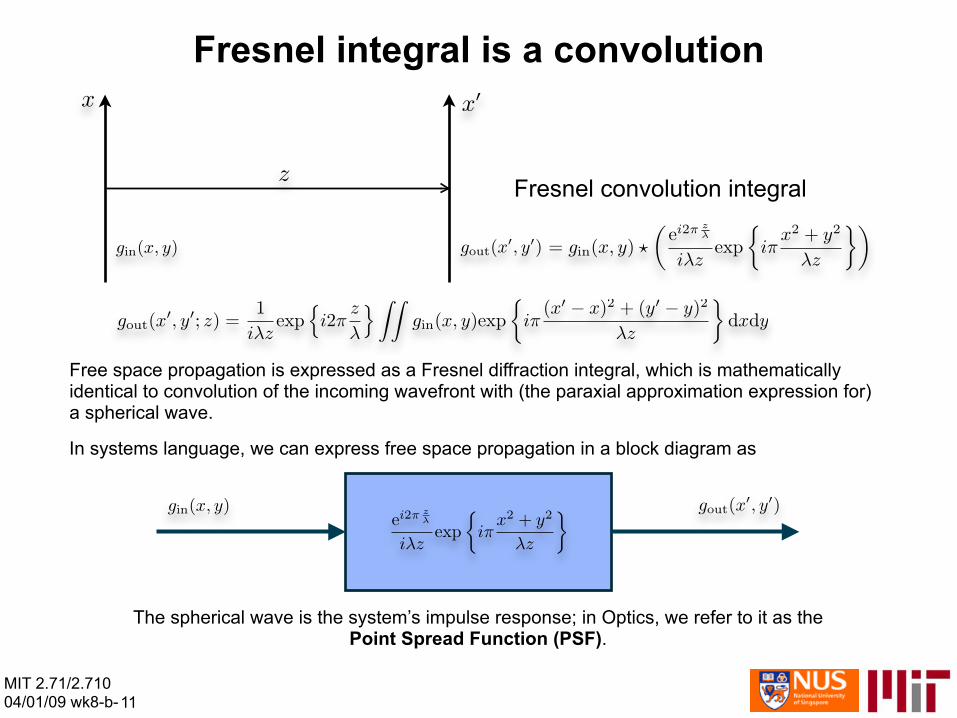
Fresnel integral is a convolution
Fresnel convolution integral
Free space propagation is expressed as a Fresnel diffraction integral, which is mathematically identical to convolution of the incoming wavefront with (the paraxial approximation expression for) a spherical wave.
In systems language, we can express free space propagation in a block diagram as
The spherical wave is the system’s impulse response; in Optics, we refer to it as thePoint Spread Function (PSF).
MIT 2.71/2.710 04/01/09 wk8-b-11
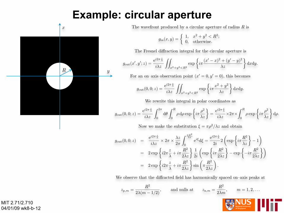
Example: circular aperture
MIT 2.71/2.710 04/01/09 wk8-b-12
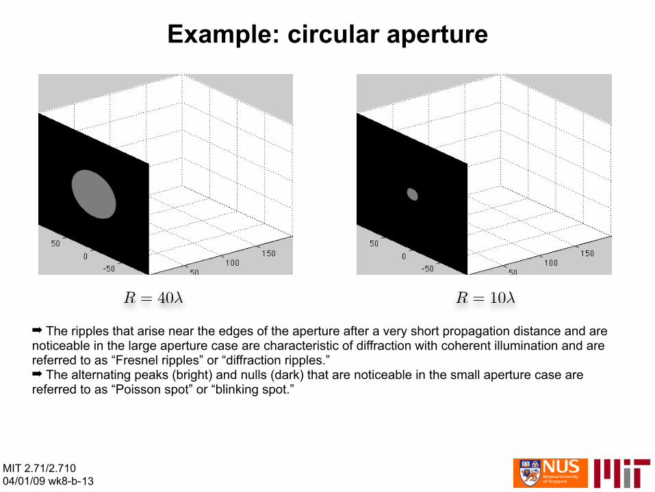
Example: circular aperture
➡ The ripples that arise near the edges of the aperture after a very short propagation distance and are noticeable in the large aperture case are characteristic of diffraction with coherent illumination and are referred to as “Fresnel ripples” or “diffraction ripples.” ➡ The alternating peaks (bright) and nulls (dark) that are noticeable in the small aperture case are referred to as “Poisson spot” or “blinking spot.”
MIT 2.71/2.710 04/01/09 wk8-b-13

Example: rectangular aperture
➡ Fresnel ripples are again noticeable in the large aperture case but produce a different ripple structure because of the rectangular geometry. ➡ The diffraction pattern from the small aperture changes qualitatively after some propagation distance; it begins to look like a sinc function, the Fourier transform of the boxcar function. We will explain this phenomenon quantitatively very soon; we refer to it as the Fraunhofer diffraction regime. ➡ Fraunhofer diffraction occurs in the case of the large aperture as well, but after a longer propagation distance (we will quantify that as well.)
MIT 2.71/2.710 04/01/09 wk8-b-14

MIT OpenCourseWarehttp://ocw.mit.edu
2.71 / 2.710 Optics Spring 2009
For information about citing these materials or our Terms of Use, visit: http://ocw.mit.edu/terms.