Air-Conditioners PUZ-ZM HA KA · interior antes de instalar o aparelho de ar condicionado. ......
16
TIL INSTALLATØREN FÖR INSTALLATÖREN PARA O INSTALADOR PER L’INSTALLATORE PARA EL INSTALADOR VOOR DE INSTALLATEUR POUR L’INSTALLATEUR FÜR INSTALLATEURE FOR INSTALLER ΓΙΑ ΑΥΤΟΝ ΠΟΥ ΚΑΝΕΙ ΤΗΝ ΕΓΚΑΤΑΣΤΑΣΗ INSTALLATION MANUAL For safe and correct use, read this manual and the indoor unit installation manual thoroughly before installing the air-conditioner unit. INSTALLATIONSHANDBUCH Aus Sicherheitsgründen und zur richtigen Verwendung vor der Installation die vorliegende Bedienungsanleitung und die Installationsanleitung der Innenanlage gründlich durchlesen die Klimaanlage. MANUEL D’INSTALLATION Avant d’installer le climatiseur, lire attentivement ce manuel, ainsi que le manuel d’installation de l’appareil intérieur pour une utilisation sûre et correcte. INSTALLATIEHANDLEIDING Lees deze handleiding en de installatiehandleiding van het binnenapparaat zorgvuldig door voordat u met het installeren van de airconditioner begint. MANUAL DE INSTALACIÓN Para un uso correcto y seguro, lea detalladamente este manual y el manual de instalación de la unidad interior antes de instalar la unidad de aire acondicionado. MANUALE DI INSTALLAZIONE Per un uso sicuro e corretto, leggere attentamente il presente manuale ed il manuale d’installazione dell’unità interna prima di installare il condizionatore d’aria. EΓΧEIPIΔIO OΔHΓIΩN EΓKATAΣTAΣHΣ Για σωστή και ασφαλή χρήση, διαβάστε προσεκτικά αυτό το εγχειρίδιο καθώς και το εγχειρίδιο εγκατάστασης της εσωτερικής μονάδας, προτού εγκαταστήσετε τη μονάδα του κλιματιστικού. MANUAL DE INSTALAÇÃO Para uma utilização segura e correcta, leia atentamente este manual e o manual de instalação da unidade interior antes de instalar o aparelho de ar condicionado. INSTALLATIONSMANUAL Læs af sikkerhedshensyn denne manual samt manualen til installation af indendørsenheden grundigt, før du installerer klimaanlægget. INSTALLATIONSMANUAL Läs bruksanvisningen och inomhusenhetens installationshandbok noga innan luftkonditioneringen installeras så att den används på ett säkert och korrekt sätt. INSTALLASJONSHÅNDBOK For å sikre trygg og riktig bruk skal denne håndboken samt installasjonshåndboken for innendørsenheten leses grundig gjennom før du installerer klimaanleggenheten. INSTRUKCJA MONTAŻU Aby zapewnić bezpieczne i prawidłowe korzystanie z urządzenia, przed montażem klimatyzatora należy dokładnie zapoznać się z treścią niniejszej instrukcji oraz instrukcji montażu jednostki wewnętrznej. English Deutsch Français Nederlands Español Italiano Eλληνικά Português Dansk Svenska Norsk Polski Air-Conditioners PUZ-ZM• HA PUZ-ZM• KA FOR MONTØR DLA INSTALATORA
Transcript of Air-Conditioners PUZ-ZM HA KA · interior antes de instalar o aparelho de ar condicionado. ......
TIL INSTALLATØREN
FÖR INSTALLATÖREN
PARA O INSTALADOR
PER L’INSTALLATORE
PARA EL INSTALADOR
VOOR DE INSTALLATEUR
POUR L’INSTALLATEUR
FÜR INSTALLATEURE
FOR INSTALLER
ΓΙΑ ΑΥΤΟΝ ΠΟΥ ΚΑΝΕΙ ΤΗΝ ΕΓΚΑΤΑΣΤΑΣΗ
INSTALLATION MANUALFor safe and correct use, read this manual and the indoor unit installation manual thoroughly before installing the air-conditioner unit.
INSTALLATIONSHANDBUCHAus Sicherheitsgründen und zur richtigen Verwendung vor der Installation die vorliegende Bedienungsanleitung und die Installationsanleitung der Innenanlage gründlich durchlesen die Klimaanlage.
MANUEL D’INSTALLATIONAvant d’installer le climatiseur, lire attentivement ce manuel, ainsi que le manuel d’installation de l’appareil intérieur pour une utilisation sûre et correcte.
INSTALLATIEHANDLEIDINGLees deze handleiding en de installatiehandleiding van het binnenapparaat zorgvuldig door voordat u met het installeren van de airconditioner begint.
MANUAL DE INSTALACIÓNPara un uso correcto y seguro, lea detalladamente este manual y el manual de instalación de la unidad interior antes de instalar la unidad de aire acondicionado.
MANUALE DI INSTALLAZIONEPer un uso sicuro e corretto, leggere attentamente il presente manuale ed il manuale d’installazione dell’unità interna prima di installare il condizionatore d’aria.
EΓΧEIPIΔIO OΔHΓIΩN EΓKATAΣTAΣHΣΓια σωστή και ασφαλή χρήση, διαβάστε προσεκτικά αυτό το εγχειρίδιο καθώς και το εγχειρίδιο εγκατάστασης της εσωτερικής μονάδας, προτού εγκαταστήσετε τη μονάδα του κλιματιστικού.
MANUAL DE INSTALAÇÃOPara uma utilização segura e correcta, leia atentamente este manual e o manual de instalação da unidade interior antes de instalar o aparelho de ar condicionado.
INSTALLATIONSMANUALLæs af sikkerhedshensyn denne manual samt manualen til installation af indendørsenheden grundigt, før du installerer klimaanlægget.
INSTALLATIONSMANUALLäs bruksanvisningen och inomhusenhetens installationshandbok noga innan luftkonditioneringen installeras så att den används på ett säkert och korrekt sätt.
INSTALLASJONSHÅNDBOKFor å sikre trygg og riktig bruk skal denne håndboken samt installasjonshåndboken for innendørsenheten leses grundig gjennom før du installerer klimaanleggenheten.
INSTRUKCJA MONTAŻUAby zapewnić bezpieczne i prawidłowe korzystanie z urządzenia, przed montażem klimatyzatora należy dokładnie zapoznać się z treścią niniejszej instrukcji oraz instrukcji montażu jednostki wewnętrznej.
English
Deutsch
Français
Nederlands
Español
Italiano
Eλληνικά
Português
Dansk
Svenska
Norsk
Polski
Air-ConditionersPUZ-ZM•HAPUZ-ZM•KA
FOR MONTØR
DLA INSTALATORA
BH79D314H06_EN.indd 1 2017/02/10 8:46:42
2
Contents
1. Safety precautions
After installation work has been completed, explain the “Safety Precautions,” use, and maintenance of the unit to the customer according to the information in the Operation Manual and perform the test run to ensure normal operation. Both the Installation Manual and Operation Manual must be given to the user for keeping. These manuals must be passed on to subsequent users.
: Indicates a part which must be grounded.
Warning:Carefully read the labels affixed to the main unit./ : Indicates warnings and cautions when using R32 refrigerant.
Warning:• The unit must not be installed by the user. Ask a dealer or an authorized techni-
cian to install and repair the unit. If the unit is installed incorrectly, water leakage, electric shock, or fire may result.
• For installation and relocation work, follow the instructions in the Installation Manual and use tools and pipe components specifically made for use with R32 refrigerant. If pipe components not designed for R32 refrigerant are used and the unit is not installed correctly, the pipes may burst and cause damage or injuries. In addition, water leakage, electric shock, or fire may result.
• The unit must be installed according to the instructions in order to minimize the risk of damage from earthquakes, typhoons, or strong winds. An incorrectly in-stalled unit may fall down and cause damage or injuries.
• The unit must be securely installed on a structure that can sustain its weight. If the unit is mounted on an unstable structure, it may fall down and cause damage or injuries.
• If the air conditioner is installed in a small room, measures must be taken to prevent the refrigerant concentration in the room from exceeding the safety limit in the event of refrigerant leakage. Consult a dealer regarding the appropriate measures to prevent the allowable concentration from being exceeded. Should the refrigerant leak and cause the concentration limit to be exceeded, hazards due to lack of oxygen in the room may result.
• Ventilate the room if refrigerant leaks during operation. If refrigerant comes into contact with a flame, poisonous gases will be released.
• All electric work must be performed by a qualified technician according to local regulations and the instructions given in this manual. The units must be powered by dedicated power lines and the correct voltage and circuit breakers must be used. Power lines with insufficient capacity or incorrect electrical work may result in electric shock or fire.
• Use C1220 copper phosphorus, for copper and copper alloy seamless pipes, to connect the refrigerant pipes. If the pipes are not connected correctly, the unit will not be properly grounded and electric shock may result.
• Use only specified cables for wiring. The wiring connections must be made se-curely with no tension applied on the terminal connections. Also, never splice the cables for wiring (unless otherwise indicated in this document).
Failure to observe these instructions may result in overheating or a fire.• If the supply cord is damaged, it must be replaced by the manufacturer, its service
agent or similarly qualified persons in order to avoid hazard.• The appliance shall be installed in accordance with national wiring regulations.• The terminal block cover panel of the outdoor unit must be firmly attached. If the
cover panel is mounted incorrectly and dust and moisture enter the unit, electric shock or fire may result.
• When installing or relocating, or servicing the air conditioner, use only the speci-fied refrigerant (R32) to charge the refrigerant lines. Do not mix it with any other refrigerant and do not allow air to remain in the lines.
If air is mixed with the refrigerant, then it can be the cause of abnormal high pres-sure in the refrigerant line, and may result in an explosion and other hazards.
The use of any refrigerant other than that specified for the system will cause me-chanical failure or system malfunction or unit breakdown. In the worst case, this could lead to a serious impediment to securing product safety.
• Use only accessories authorized by Mitsubishi Electric and ask a dealer or an au-thorized technician to install them. If accessories are incorrectly installed, water leakage, electric shock, or fire may result.
• Do not alter the unit. Consult a dealer for repairs. If alterations or repairs are not performed correctly, water leakage, electric shock, or fire may result.
• The user should never attempt to repair the unit or transfer it to another location. If the unit is installed incorrectly, water leakage, electric shock, or fire may result. If the air conditioner must be repaired or moved, ask a dealer or an authorized technician.
• After installation has been completed, check for refrigerant leaks. If refrigerant leaks into the room and comes into contact with the flame of a heater or portable cooking range, poisonous gases will be released.
• Do not use means to accelerate the defrosting process or to clean, other than those recommended by the manufacturer.
• The appliance shall be stored in a room without continuously operating ignition sources (for example: open flames, an operating gas appliance or an operating electric heater).
• Do not pierce or burn.• Be aware that refrigerants may not contain an odour./ Pipe-work shall be protected from physical damage.• The installation of pipe-work shall be kept to a minimum.• Compliance with national gas regulations shall be observed.• Keep any required ventilation openings clear of obstruction./ Do not use low temperature solder alloy in case of brazing the refrigerant pipes./ When performing brazing work, be sure to ventilate the room sufficiently. Make sure that there are no hazardous or flammable materials nearby. When performing the work in a closed room, small room, or similar location, make
sure that there are no refrigerant leaks before performing the work. If refrigerant leaks and accumulates, it may ignite or poisonous gases may be
released./ The appliance shall be stored in a well-ventilated area where the room size cor-
responds to the room area as specified for operation./ Keep gas-burning appliances, electric heaters, and other fire sources (ignition
sources) away from the location where installation, repair, and other air condi-tioner work will be performed.
If refrigerant comes into contact with a flame, poisonous gases will be released./ Do not smoke during work and transportation.
Warning:Describes precautions that must be observed to prevent danger of injury or death to the user.
Caution:Describes precautions that must be observed to prevent damage to the unit.
Note: This symbol mark is for EU countries only.This symbol mark is according to the directive 2012/19/EU Article 14 Information for users and Annex IX.Your MITSUBISHI ELECTRIC product is designed and manufactured with high quality materials and components which can be recycled and reused.This symbol means that electrical and electronic equipment, at their end-of-life, should be disposed of separately from your household waste.Please, dispose of this equipment at your local community waste collection/recycling centre.In the European Union there are separate collection systems for used electrical and electronic product.Please, help us to conserve the environment we live in!
Caution:• Do not vent R32 into the atmosphere.
Before installing the unit, make sure you read all the “Safety precautions”.
1. Safety precautions . . . . . . . . . . . . . . . . . . . . . . . . . . . . . . . . . . . . . . . . . . . . . . . . 22. Installation location . . . . . . . . . . . . . . . . . . . . . . . . . . . . . . . . . . . . . . . . . . . . . . . 33. Installing the outdoor unit . . . . . . . . . . . . . . . . . . . . . . . . . . . . . . . . . . . . . . . . . . 74. Installing the refrigerant piping . . . . . . . . . . . . . . . . . . . . . . . . . . . . . . . . . . . . . . 75. Drainage piping work . . . . . . . . . . . . . . . . . . . . . . . . . . . . . . . . . . . . . . . . . . . . . 11
6. Electrical work . . . . . . . . . . . . . . . . . . . . . . . . . . . . . . . . . . . . . . . . . . . . . . . . . . 127. Test run . . . . . . . . . . . . . . . . . . . . . . . . . . . . . . . . . . . . . . . . . . . . . . . . . . . . . . . 148. Special functions . . . . . . . . . . . . . . . . . . . . . . . . . . . . . . . . . . . . . . . . . . . . . . . . 159. System control (Fig. 9-1) . . . . . . . . . . . . . . . . . . . . . . . . . . . . . . . . . . . . . . . . . . 1510. Specifications . . . . . . . . . . . . . . . . . . . . . . . . . . . . . . . . . . . . . . . . . . . . . . . . . 15
MEANINGS OF SYMBOLS DISPLAYED ON THE UNITWARNING
(Risk of fire)
This mark is for R32 refrigerant only. Refrigerant type is written on nameplate of outdoor unit.In case that refrigerant type is R32, this unit uses a flammable refrigerant.If refrigerant leaks and comes in contact with fire or heating part, it will create harmful gas and there is risk of fire.
Read the OPERATION MANUAL carefully before operation.
Service personnel are required to carefully read the OPERATION MANUAL and INSTALLATION MANUAL before operation.
Further information is available in the OPERATION MANUAL, INSTALLATION MANUAL, and the like.
BH79D314H06_EN.indd 2 2017/02/10 8:46:43
950
330+30
94
3 (
13
50
)
175600
370
3
1.1. Before installation Caution:
• Do not use the unit in an unusual environment. If the air conditioner is installed in areas exposed to steam, volatile oil (including machine oil), or sulfuric gas, areas exposed to high salt content such as the seaside, or areas where the unit will be covered by snow, the performance can be significantly reduced and the internal parts can be damaged.
• Do not install the unit where combustible gases may leak, be produced, flow, or accumulate. If combustible gas accumulates around the unit, fire or explosion may result.
1. Safety precautions
• The outdoor unit produces condensation during the heating operation. Make sure to provide drainage around the outdoor unit if such condensation is likely to cause damage.
• When installing the unit in a hospital or communications office, be prepared for noise and electronic interference. Inverters, home appliances, high-frequency medical equipment, and radio communications equipment can cause the air con-ditioner to malfunction or breakdown. The air conditioner may also affect medical equipment, disturbing medical care, and communications equipment, harming the screen display quality.
1.2. Before installation (relocation) Caution:
• Be extremely careful when transporting or installing the units. Two or more per-sons are needed to handle the unit, as it weighs 20 kg or more. Do not grasp the packaging bands. Wear protective gloves to remove the unit from the packaging and to move it, as you can injure your hands on the fins or the edge of other parts.
• Be sure to safely dispose of the packaging materials. Packaging materials, such as nails and other metal or wooden parts may cause stabs or other injuries.
• The base and attachments of the outdoor unit must be periodically checked for looseness, cracks or other damage. If such defects are left uncorrected, the unit may fall down and cause damage or injuries.
• Do not clean the air conditioner unit with water. Electric shock may result.• Tighten all flare nuts to specification using a torque wrench. If tightened too
much, the flare nut can break after an extended period and refrigerant can leak out.
1.3. Before electric work Caution:
• Be sure to install circuit breakers. If not installed, electric shock may result.• For the power lines, use standard cables of sufficient capacity. Otherwise, a short
circuit, overheating, or fire may result.• When installing the power lines, do not apply tension to the cables. If the con-
nections are loosened, the cables can snap or break and overheating or fire may result.
• Be sure to ground the unit. Do not connect the ground wire to gas or water pipes, lightning rods, or telephone grounding lines. If the unit is not properly grounded, electric shock may result.
• Use circuit breakers (ground fault interrupter, isolating switch (+B fuse), and molded case circuit breaker) with the specified capacity. If the circuit breaker capacity is larger than the specified capacity, breakdown or fire may result.
1.4. Before starting the test run Caution:
• Turn on the main power switch more than 12 hours before starting operation. Starting operation just after turning on the power switch can severely damage the internal parts. Keep the main power switch turned on during the operation season.
• Before starting operation, check that all panels, guards and other protective parts are correctly installed. Rotating, hot, or high voltage parts can cause injuries.
• Do not touch any switch with wet hands. Electric shock may result.• Do not touch the refrigerant pipes with bare hands during operation. The refriger-
ant pipes are hot or cold depending on the condition of the flowing refrigerant. If you touch the pipes, burns or frostbite may result.
• After stopping operation, be sure to wait at least five minutes before turning off the main power switch. Otherwise, water leakage or breakdown may result.
1.5. Using R32 refrigerant air conditioners Caution:
• Use C1220 copper phosphorus, for copper and copper alloy seamless pipes, to connect the refrigerant pipes. Make sure the insides of the pipes are clean and do not contain any harmful contaminants such as sulfuric compounds, oxidants, debris, or dust. Use pipes with the specified thickness. (Refer to 4.1.) Note the following if reusing existing pipes that carried R22 refrigerant.
- Replace the existing flare nuts and flare the flared sections again. - Do not use thin pipes. (Refer to 4.1.)• Store the pipes to be used during installation indoors and keep both ends of the
pipes sealed until just before brazing. (Leave elbow joints, etc. in their packag-ing.) If dust, debris, or moisture enters the refrigerant lines, oil deterioration or compressor breakdown may result.
• Use ester oil, ether oil, alkylbenzene oil (small amount) as the refrigeration oil applied to the flared sections. If mineral oil is mixed in the refrigeration oil, oil deterioration may result.
• Do not use refrigerant other than R32 refrigerant.
• Servicing shall be performed only as recommended by the manufacturer.• Use the following tools specifically designed for use with R32 refrigerant. The following tools are necessary to use R32 refrigerant. Contact your nearest
dealer for any questions.
Tools (for R32)Gauge manifold Flare tool
Charge hose Size adjustment gaugeGas leak detector Vacuum pump adapter
Torque wrench Electronic refrigerant charging scale
• Be sure to use the correct tools. If dust, debris, or moisture enters the refrigerant lines, refrigeration oil deterioration may result.
2. Installation location
Fig. 2-1
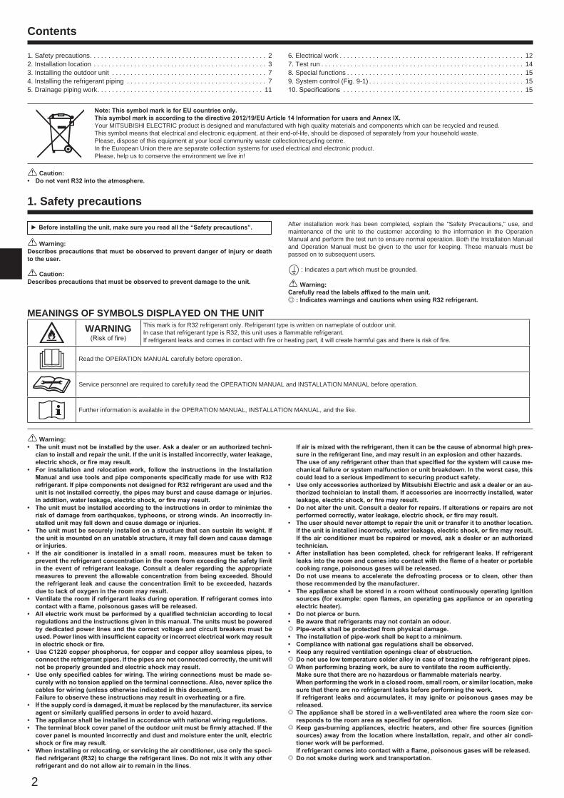
2.1. Refrigerant pipe (Fig. 2-1) Check that the difference between the heights of the indoor and outdoor
units, the length of refrigerant pipe, and the number of bends in the pipe are within the limits shown below.
Models A Pipe length (one way)
B Height difference
C Number of bends (one way)
ZM35, 50 Max. 50 m Max. 30 m Max. 15ZM60, 71 Max. 55 m Max. 30 m Max. 15
• Height difference limitations are binding regardless of which unit, indoor or out-door, is positioned higher.
D Indoor unit E Outdoor unit
A
B
E
D
C
BH79D314H06_EN.indd 3 2017/02/10 8:46:43
4
B
2. Installation location
Fig. 2-5
Fig. 2-4
Fig. 2-6
Fig. 2-3
Fig. 2-2
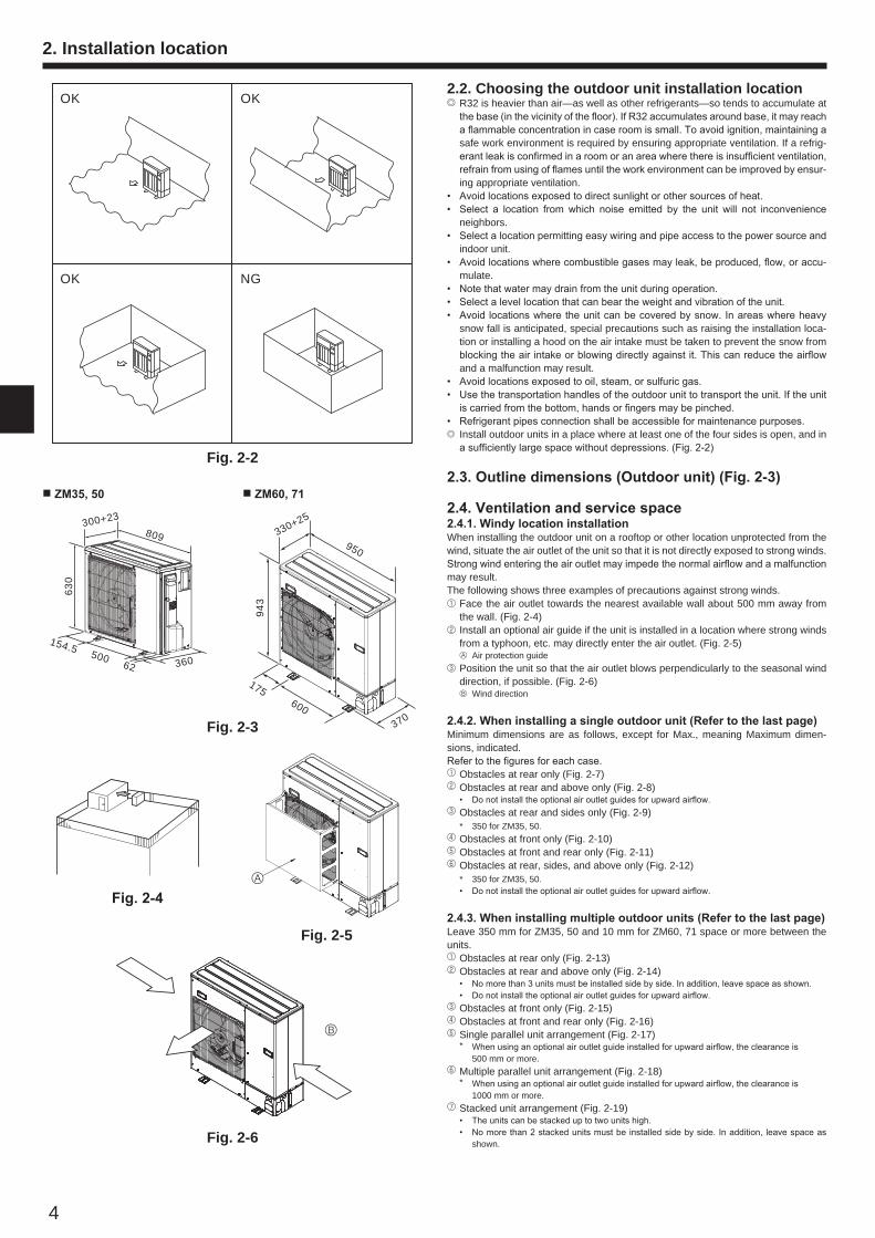
2.2. Choosing the outdoor unit installation location/R32 is heavier than air—as well as other refrigerants—so tends to accumulate at
the base (in the vicinity of the floor). If R32 accumulates around base, it may reach a flammable concentration in case room is small. To avoid ignition, maintaining a safe work environment is required by ensuring appropriate ventilation. If a refrig-erant leak is confirmed in a room or an area where there is insufficient ventilation, refrain from using of flames until the work environment can be improved by ensur-ing appropriate ventilation.
• Avoid locations exposed to direct sunlight or other sources of heat.• Select a location from which noise emitted by the unit will not inconvenience
neighbors.• Select a location permitting easy wiring and pipe access to the power source and
indoor unit.• Avoid locations where combustible gases may leak, be produced, flow, or accu-
mulate.• Note that water may drain from the unit during operation.• Select a level location that can bear the weight and vibration of the unit.• Avoid locations where the unit can be covered by snow. In areas where heavy
snow fall is anticipated, special precautions such as raising the installation loca-tion or installing a hood on the air intake must be taken to prevent the snow from blocking the air intake or blowing directly against it. This can reduce the airflow and a malfunction may result.
• Avoid locations exposed to oil, steam, or sulfuric gas.• Use the transportation handles of the outdoor unit to transport the unit. If the unit
is carried from the bottom, hands or fingers may be pinched.• Refrigerant pipes connection shall be accessible for maintenance purposes./ Install outdoor units in a place where at least one of the four sides is open, and in
a sufficiently large space without depressions. (Fig. 2-2)
2.3. Outline dimensions (Outdoor unit) (Fig. 2-3)
2.4. Ventilation and service space2.4.1. Windy location installationWhen installing the outdoor unit on a rooftop or other location unprotected from the wind, situate the air outlet of the unit so that it is not directly exposed to strong winds. Strong wind entering the air outlet may impede the normal airflow and a malfunction may result.The following shows three examples of precautions against strong winds.1 Face the air outlet towards the nearest available wall about 500 mm away from
the wall. (Fig. 2-4)2 Install an optional air guide if the unit is installed in a location where strong winds
from a typhoon, etc. may directly enter the air outlet. (Fig. 2-5) A Air protection guide3 Position the unit so that the air outlet blows perpendicularly to the seasonal wind
direction, if possible. (Fig. 2-6) B Wind direction
2.4.2. When installing a single outdoor unit (Refer to the last page)Minimum dimensions are as follows, except for Max., meaning Maximum dimen-sions, indicated.Refer to the figures for each case.1 Obstacles at rear only (Fig. 2-7)2 Obstacles at rear and above only (Fig. 2-8) • Do not install the optional air outlet guides for upward airflow.3 Obstacles at rear and sides only (Fig. 2-9) * 350 for ZM35, 50.4 Obstacles at front only (Fig. 2-10)5 Obstacles at front and rear only (Fig. 2-11)6 Obstacles at rear, sides, and above only (Fig. 2-12) * 350 for ZM35, 50. • Do not install the optional air outlet guides for upward airflow.
2.4.3. When installing multiple outdoor units (Refer to the last page)Leave 350 mm for ZM35, 50 and 10 mm for ZM60, 71 space or more between the units.1 Obstacles at rear only (Fig. 2-13)2 Obstacles at rear and above only (Fig. 2-14) • No more than 3 units must be installed side by side. In addition, leave space as shown. • Do not install the optional air outlet guides for upward airflow.3 Obstacles at front only (Fig. 2-15)4 Obstacles at front and rear only (Fig. 2-16)5 Single parallel unit arrangement (Fig. 2-17) * When using an optional air outlet guide installed for upward airflow, the clearance is 500 mm or more.6 Multiple parallel unit arrangement (Fig. 2-18) * When using an optional air outlet guide installed for upward airflow, the clearance is 1000 mm or more.7 Stacked unit arrangement (Fig. 2-19) • The units can be stacked up to two units high. • No more than 2 stacked units must be installed side by side. In addition, leave space as
shown.
ZM35, 50 ZM60, 71
A
950
330+25
943
175600
370
809
500 62
154.5
300+23
630
360
OK OK
OK NG
BH79D314H06_EN.indd 4 2017/02/10 8:46:50
5
2. Installation location
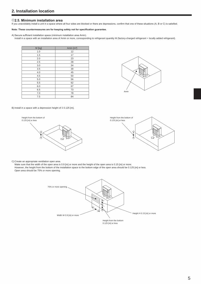
/ 2.5. Minimum installation areaIf you unavoidably install a unit in a space where all four sides are blocked or there are depressions, confirm that one of these situations (A, B or C) is satisfied.
Note: These countermeasures are for keeping safety not for specification guarantee.
A) Secure sufficient installation space (minimum installation area Amin). Install in a space with an installation area of Amin or more, corresponding to refrigerant quantity M (factory-charged refrigerant + locally added refrigerant).
C) Create an appropriate ventilation open area. Make sure that the width of the open area is 0.9 [m] or more and the height of the open area is 0.15 [m] or more. However, the height from the bottom of the installation space to the bottom edge of the open area should be 0.125 [m] or less. Open area should be 75% or more opening.
B) Install in a space with a depression height of [ 0.125 [m].
Amin
Height from the bottom of 0.125 [m] or less
75% or more opening
Height from the bottom of 0.125 [m] or less
Width W 0.9 [m] or more
Height from the bottom 0.125 [m] or less
Height H 0.15 [m] or more
M [kg] Amin [m²]1.0 121.5 172.0 232.5 283.0 343.5 394.0 454.5 505.0 565.5 626.0 676.5 737.0 787.5 84
BH79D314H06_EN.indd 5 2017/02/10 8:46:51
6
2. Installation location
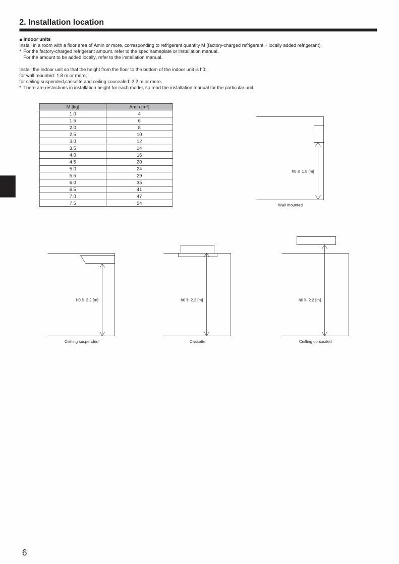
Indoor unitsInstall in a room with a floor area of Amin or more, corresponding to refrigerant quantity M (factory-charged refrigerant + locally added refrigerant).* For the factory-charged refrigerant amount, refer to the spec nameplate or installation manual. For the amount to be added locally, refer to the installation manual.
Install the indoor unit so that the height from the floor to the bottom of the indoor unit is h0; for wall mounted: 1.8 m or more; for ceiling suspended,cassette and ceiling coucealed: 2.2 m or more.* There are restrictions in installation height for each model, so read the installation manual for the particular unit.
M [kg] Amin [m²]1.0 41.5 62.0 82.5 103.0 123.5 144.0 164.5 205.0 245.5 296.0 356.5 417.0 477.5 54 Wall mounted
h0 ] 1.8 [m]
Ceilling concealedCassetteCeilling suspended
h0 ] 2.2 [m]h0 ] 2.2 [m]h0 ] 2.2 [m]
BH79D314H06_EN.indd 6 2017/02/10 8:46:51
7
Fig. 3-1
3. Installing the outdoor unit
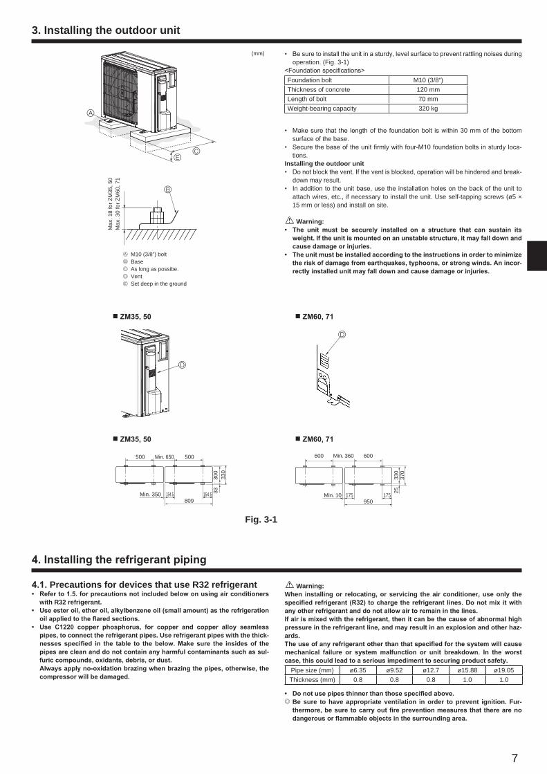
• Be sure to install the unit in a sturdy, level surface to prevent rattling noises during operation. (Fig. 3-1)
<Foundation specifications>Foundation bolt M10 (3/8")Thickness of concrete 120 mmLength of bolt 70 mmWeight-bearing capacity 320 kg
• Make sure that the length of the foundation bolt is within 30 mm of the bottom surface of the base.
• Secure the base of the unit firmly with four-M10 foundation bolts in sturdy loca-tions.
Installing the outdoor unit• Do not block the vent. If the vent is blocked, operation will be hindered and break-
down may result.• In addition to the unit base, use the installation holes on the back of the unit to
attach wires, etc., if necessary to install the unit. Use self-tapping screws (ø5 × 15 mm or less) and install on site.
Warning:• The unit must be securely installed on a structure that can sustain its
weight. If the unit is mounted on an unstable structure, it may fall down and cause damage or injuries.
• The unit must be installed according to the instructions in order to minimize the risk of damage from earthquakes, typhoons, or strong winds. An incor-rectly installed unit may fall down and cause damage or injuries.
(mm)
B
D
Min. 10
600 600Min. 360
175 175950
2533
037
0
4. Installing the refrigerant piping
4.1. Precautions for devices that use R32 refrigerant• Refer to 1.5. for precautions not included below on using air conditioners
with R32 refrigerant.• Use ester oil, ether oil, alkylbenzene oil (small amount) as the refrigeration
oil applied to the flared sections.• Use C1220 copper phosphorus, for copper and copper alloy seamless
pipes, to connect the refrigerant pipes. Use refrigerant pipes with the thick-nesses specified in the table to the below. Make sure the insides of the pipes are clean and do not contain any harmful contaminants such as sul-furic compounds, oxidants, debris, or dust.
Always apply no-oxidation brazing when brazing the pipes, otherwise, the compressor will be damaged.
Warning:When installing or relocating, or servicing the air conditioner, use only the specified refrigerant (R32) to charge the refrigerant lines. Do not mix it with any other refrigerant and do not allow air to remain in the lines. If air is mixed with the refrigerant, then it can be the cause of abnormal high pressure in the refrigerant line, and may result in an explosion and other haz-ards.The use of any refrigerant other than that specified for the system will cause mechanical failure or system malfunction or unit breakdown. In the worst case, this could lead to a serious impediment to securing product safety.
Pipe size (mm) ø6.35 ø9.52 ø12.7 ø15.88 ø19.05Thickness (mm) 0.8 0.8 0.8 1.0 1.0
• Do not use pipes thinner than those specified above./ Be sure to have appropriate ventilation in order to prevent ignition. Fur-
thermore, be sure to carry out fire prevention measures that there are no dangerous or flammable objects in the surrounding area.
ZM60, 71 ZM35, 50
ZM60, 71 ZM35, 50
500 Min. 650 500
300
330
33Min. 350 154.5 154.5809
A
CE
Max
. 18
for Z
M35
, 50
Max
. 30
for Z
M60
, 71
A M10 (3/8”) boltB BaseC As long as possibe.D VentE Set deep in the ground
D
BH79D314H06_EN.indd 7 2017/02/10 8:46:52
90°
± 0.
5°ø
A
R0.4~R
0.8
45°± 2 °
90°
± 0.
5°øA
R0.4 - R0.8
45°± 2 °
8
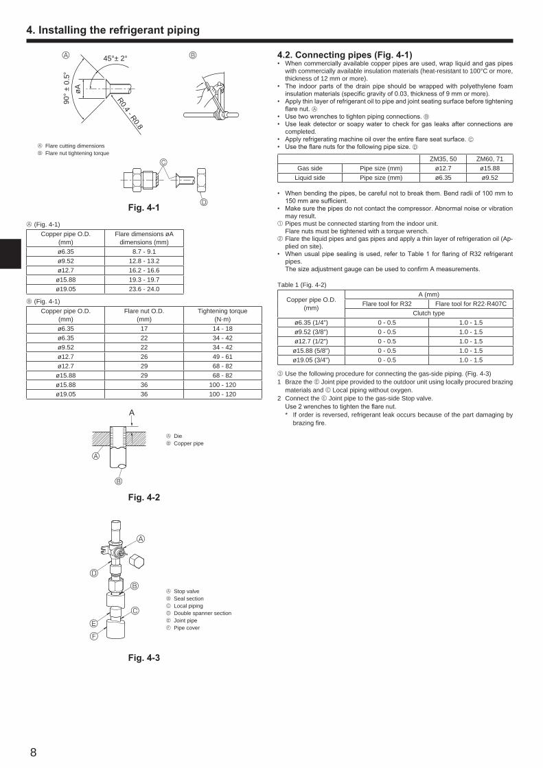
4.2. Connecting pipes (Fig. 4-1)• When commercially available copper pipes are used, wrap liquid and gas pipes
with commercially available insulation materials (heat-resistant to 100°C or more, thickness of 12 mm or more).
• The indoor parts of the drain pipe should be wrapped with polyethylene foam insulation materials (specific gravity of 0.03, thickness of 9 mm or more).
• Apply thin layer of refrigerant oil to pipe and joint seating surface before tightening flare nut. A
• Use two wrenches to tighten piping connections. B• Use leak detector or soapy water to check for gas leaks after connections are
completed.• Apply refrigerating machine oil over the entire flare seat surface. C• Use the flare nuts for the following pipe size. D
ZM35, 50 ZM60, 71Gas side Pipe size (mm) ø12.7 ø15.88
Liquid side Pipe size (mm) ø6.35 ø9.52
• When bending the pipes, be careful not to break them. Bend radii of 100 mm to 150 mm are sufficient.
• Make sure the pipes do not contact the compressor. Abnormal noise or vibration may result.
1 Pipes must be connected starting from the indoor unit. Flare nuts must be tightened with a torque wrench.2 Flare the liquid pipes and gas pipes and apply a thin layer of refrigeration oil (Ap-
plied on site).• When usual pipe sealing is used, refer to Table 1 for flaring of R32 refrigerant
pipes. The size adjustment gauge can be used to confirm A measurements.
Table 1 (Fig. 4-2)
Copper pipe O.D. (mm)
A (mm)Flare tool for R32 Flare tool for R22·R407C
Clutch typeø6.35 (1/4") 0 - 0.5 1.0 - 1.5ø9.52 (3/8") 0 - 0.5 1.0 - 1.5ø12.7 (1/2") 0 - 0.5 1.0 - 1.5
ø15.88 (5/8") 0 - 0.5 1.0 - 1.5ø19.05 (3/4") 0 - 0.5 1.0 - 1.5
3 Use the following procedure for connecting the gas-side piping. (Fig. 4-3)1 Braze the E Joint pipe provided to the outdoor unit using locally procured brazing
materials and C Local piping without oxygen.2 Connect the E Joint pipe to the gas-side Stop valve. Use 2 wrenches to tighten the flare nut. * If order is reversed, refrigerant leak occurs because of the part damaging by
brazing fire.
A (Fig. 4-1)Copper pipe O.D.
(mm)Flare dimensions øA
dimensions (mm)ø6.35 8.7 - 9.1ø9.52 12.8 - 13.2ø12.7 16.2 - 16.6ø15.88 19.3 - 19.7ø19.05 23.6 - 24.0
B (Fig. 4-1)Copper pipe O.D.
(mm)Flare nut O.D.
(mm)Tightening torque
(N·m)ø6.35 17 14 - 18ø6.35 22 34 - 42ø9.52 22 34 - 42ø12.7 26 49 - 61ø12.7 29 68 - 82
ø15.88 29 68 - 82ø15.88 36 100 - 120ø19.05 36 100 - 120
A Flare cutting dimensionsB Flare nut tightening torque
A B
C
A DieB Copper pipe
A
B
A
4. Installing the refrigerant piping
Fig. 4-3
Fig. 4-2
Fig. 4-1
A
B
C
D
E
F
A Stop valveB Seal sectionC Local pipingD Double spanner sectionE Joint pipeF Pipe cover
D
BH79D314H06_EN.indd 8 2017/02/10 8:46:52
9
4. Installing the refrigerant piping
Fig. 4-4
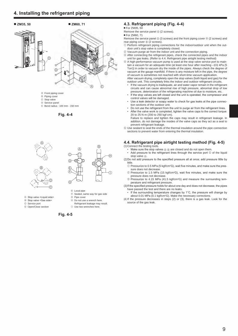
A Front piping coverB Piping coverC Stop valveD Service panelE Bend radius : 100 mm - 150 mm
4.3. Refrigerant piping (Fig. 4-4) For ZM35, 50
Remove the service panel D (2 screws). For ZM60, 71
Remove the service panel D (3 screws) and the front piping cover A (2 screws) and rear piping cover B (2 screws).1 Perform refrigerant piping connections for the indoor/outdoor unit when the out-
door unit’s stop valve is completely closed.2 Vacuum-purge air from the indoor unit and the connection piping.3 After connecting the refrigerant pipes, check the connected pipes and the indoor
unit for gas leaks. (Refer to 4.4. Refrigerant pipe airtight testing method)4 A high-performance vacuum pump is used at the stop valve service port to main-
tain a vacuum for an adequate time (at least one hour after reaching –101 kPa (5 Torr)) in order to vacuum dry the inside of the pipes. Always check the degree of vacuum at the gauge manifold. If there is any moisture left in the pipe, the degree of vacuum is sometimes not reached with short-time vacuum application.
After vacuum drying, completely open the stop valves (both liquid and gas) for the outdoor unit. This completely links the indoor and outdoor refrigerant circuits.
• If the vacuum drying is inadequate, air and water vapor remain in the refrigerant circuits and can cause abnormal rise of high pressure, abnormal drop of low pressure, deterioration of the refrigerating machine oil due to moisture, etc.
• If the stop valves are left closed and the unit is operated, the compressor and control valves will be damaged.
• Use a leak detector or soapy water to check for gas leaks at the pipe connec-tion sections of the outdoor unit.
• Do not use the refrigerant from the unit to purge air from the refrigerant lines. • After the valve work is completed, tighten the valve caps to the correct torque:
20 to 25 N·m (200 to 250 kgf·cm). Failure to replace and tighten the caps may result in refrigerant leakage. In
addition, do not damage the insides of the valve caps as they act as a seal to prevent refrigerant leakage.
5 Use sealant to seal the ends of the thermal insulation around the pipe connection sections to prevent water from entering the thermal insulation.
4.4. Refrigerant pipe airtight testing method (Fig. 4-5)(1) Connect the testing tools. • Make sure the stop valves A B are closed and do not open them. • Add pressure to the refrigerant lines through the service port C of the liquid
stop valve A.(2) Do not add pressure to the specified pressure all at once; add pressure little by
little. 1 Pressurize to 0.5 MPa (5 kgf/cm2G), wait five minutes, and make sure the pres-
sure does not decrease. 2 Pressurize to 1.5 MPa (15 kgf/cm2G), wait five minutes, and make sure the
pressure does not decrease. 3 Pressurize to 4.15 MPa (41.5 kgf/cm2G) and measure the surrounding tem-
perature and refrigerant pressure.(3) If the specified pressure holds for about one day and does not decrease, the pipes
have passed the test and there are no leaks. • If the surrounding temperature changes by 1°C, the pressure will change by
about 0.01 MPa (0.1 kgf/cm2G). Make the necessary corrections.(4) If the pressure decreases in steps (2) or (3), there is a gas leak. Look for the
source of the gas leak.
D
A
A Stop valve <Liquid side>B Stop valve <Gas side>C Service portD Open/Close section
E Local pipeF Sealed, same way for gas sideG Pipe coverH Do not use a wrench here. Refrigerant leakage may result.I Use two wrenches here.
D
B
C
G
FE
D
C
A
Fig. 4-5
I
H
B
ZM35, 50 ZM60, 71
D
A E
C
B
BH79D314H06_EN.indd 9 2017/02/10 8:46:53
10
4. Installing the refrigerant piping
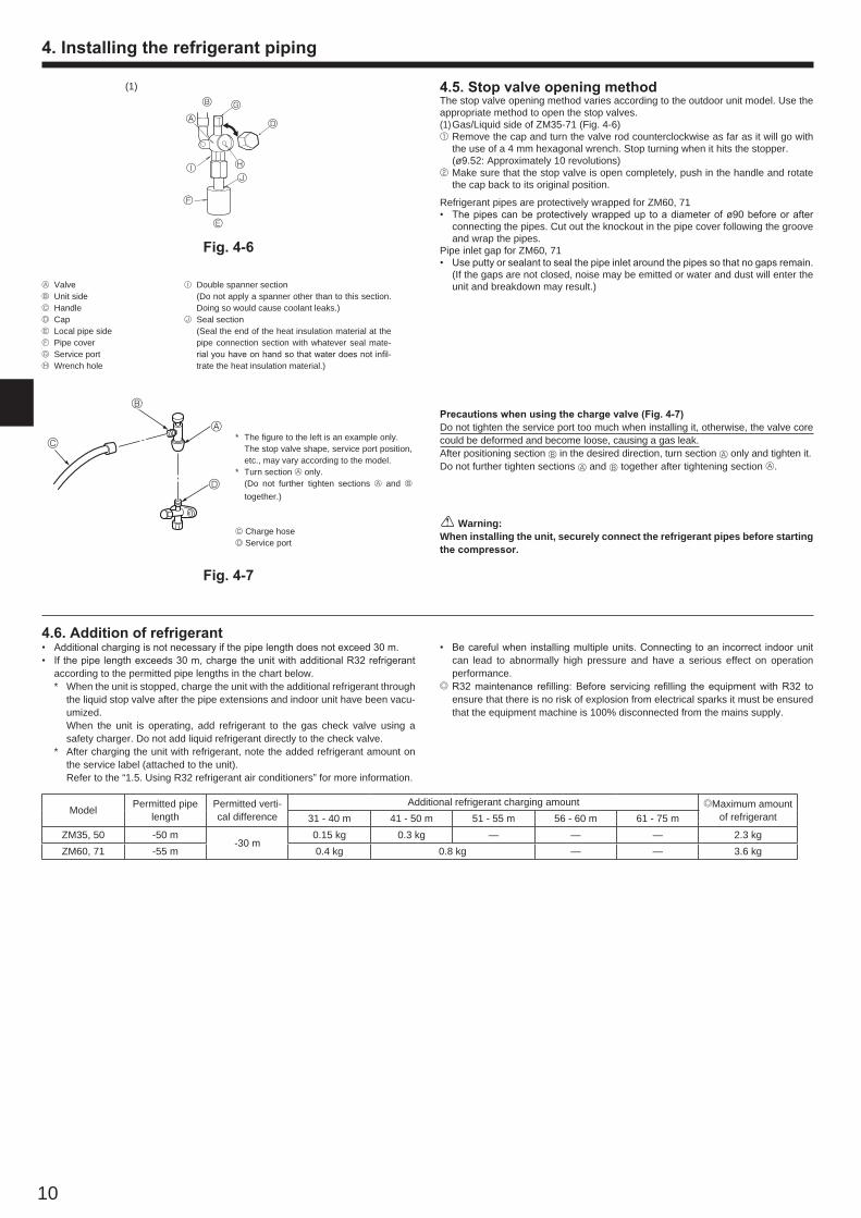
Fig. 4-6
4.5. Stop valve opening methodThe stop valve opening method varies according to the outdoor unit model. Use the appropriate method to open the stop valves.(1) Gas/Liquid side of ZM35-71 (Fig. 4-6)1 Remove the cap and turn the valve rod counterclockwise as far as it will go with
the use of a 4 mm hexagonal wrench. Stop turning when it hits the stopper. (ø9.52: Approximately 10 revolutions)2 Make sure that the stop valve is open completely, push in the handle and rotate
the cap back to its original position.
Refrigerant pipes are protectively wrapped for ZM60, 71• The pipes can be protectively wrapped up to a diameter of ø90 before or after
connecting the pipes. Cut out the knockout in the pipe cover following the groove and wrap the pipes.
Pipe inlet gap for ZM60, 71• Use putty or sealant to seal the pipe inlet around the pipes so that no gaps remain.
(If the gaps are not closed, noise may be emitted or water and dust will enter the unit and breakdown may result.)
4.6. Addition of refrigerant• Additional charging is not necessary if the pipe length does not exceed 30 m.• If the pipe length exceeds 30 m, charge the unit with additional R32 refrigerant
according to the permitted pipe lengths in the chart below. * When the unit is stopped, charge the unit with the additional refrigerant through
the liquid stop valve after the pipe extensions and indoor unit have been vacu-umized.
When the unit is operating, add refrigerant to the gas check valve using a safety charger. Do not add liquid refrigerant directly to the check valve.
* After charging the unit with refrigerant, note the added refrigerant amount on the service label (attached to the unit).
Refer to the “1.5. Using R32 refrigerant air conditioners” for more information.
• Be careful when installing multiple units. Connecting to an incorrect indoor unit can lead to abnormally high pressure and have a serious effect on operation performance.
/ R32 maintenance refilling: Before servicing refilling the equipment with R32 to ensure that there is no risk of explosion from electrical sparks it must be ensured that the equipment machine is 100% disconnected from the mains supply.
I Double spanner section (Do not apply a spanner other than to this section.
Doing so would cause coolant leaks.)J Seal section (Seal the end of the heat insulation material at the
pipe connection section with whatever seal mate-rial you have on hand so that water does not infil-trate the heat insulation material.)
A ValveB Unit sideC HandleDCapE Local pipe sideF Pipe coverG Service portH Wrench hole
Precautions when using the charge valve (Fig. 4-7)Do not tighten the service port too much when installing it, otherwise, the valve core could be deformed and become loose, causing a gas leak.After positioning section B in the desired direction, turn section A only and tighten it.Do not further tighten sections A and B together after tightening section A.
* The figure to the left is an example only. The stop valve shape, service port position,
etc., may vary according to the model.* Turn section A only. (Do not further tighten sections A and B
together.)
C Charge hoseD Service port
A
B
C
D
Fig. 4-7
(1)B G
H
E
DA
F
IJ
Warning:When installing the unit, securely connect the refrigerant pipes before starting the compressor.
Model Permitted pipe length
Permitted verti-cal difference
Additional refrigerant charging amount /Maximum amount of refrigerant31 - 40 m 41 - 50 m 51 - 55 m 56 - 60 m 61 - 75 m
ZM35, 50 -50 m-30 m
0.15 kg 0.3 kg — — — 2.3 kgZM60, 71 -55 m 0.4 kg 0.8 kg — — 3.6 kg
BH79D314H06_EN.indd 10 2017/02/10 8:46:53
11
Perform the airtight test, vacuum air purging, additional refrigerant charging (if necessary), and gas leak check.
4.7. Precautions when reusing existing R22 refrigerant pipes• Refer to the flowchart below to determine if the existing pipes can be used and if it is necessary to use a filter dryer.• If the diameter of the existing pipes is different from the specified diameter, refer to technological data materials to confirm if the pipes can be used.
Measure the existing pipe thickness and check for damage.
The existing pipe thickness meets specifica-tions and the pipes are not damaged.
Check if the existing air conditioner can operate.
After operating the cooling system for about 30minutes, do a pump down work.
Disconnect the existing air conditioner from thepipes.
Attach the new air conditioner
Test run
* Refer to 7.2.
The existing pipes cannot be reused.Use new pipes.
* If the existing air conditioner cannot operate, use a refrigerant recovery device to collect the refrigerant.
* In case existing pipes were used for gas or oil heat pump systems, be sure to use new pipes for ZM35-71 models.
The existing pipe thickness does not meetspecifications or the pipes are damaged.
4. Installing the refrigerant piping
5. Drainage piping work
Outdoor unit drainage pipe connectionWhen drain piping is necessary, use the drain socket or the drain pan (option).
ZM35, 50 ZM60, 71Drain socket PAC-SJ08DS-E PAC-SH71DS-EDrain pan PAC-SG63DP-E PAC-SG64DP-E
<Limits of refrigerant piping installation>
A Indoor unitB Outdoor unitC Multi distribution pipe (option)DHeight difference (Indoor unit-
Outdoor unit) Max. 30 mE Height difference (Indoor unit-
Indoor unit) Max. 1 mA: Main pipingB, C, D: Branch piping
ZM71 : A+B+C 55 m * “D” is for triple.
4.8. For twin/triple combination (Fig. 4-8)• When this unit is used as a FREE COMPO MULTI unit, install the refrigerant
piping with the restrictions indicated in the drawing on the left. In addition, if the restrictions are going to be exceeded, or if there are going to be combinations of indoor and outdoor units, refer to installation instructions for the indoor unit for details about the installation.
Outdoor unitPermissible total
piping lengthA+B+C+D
A+B or A+Cor
A+D
Charge-less piping length
A+B+C+DZM71 55 m and less – 30 m and less
Outdoor unit B-C or B-Dor C-D No. of bendsZM71 8 m and less Within 15
Fig. 4-8
BH79D314H06_EN.indd 11 2017/02/10 8:46:53
S3
S3S2S1
S2S1L N
12
6. Electrical work
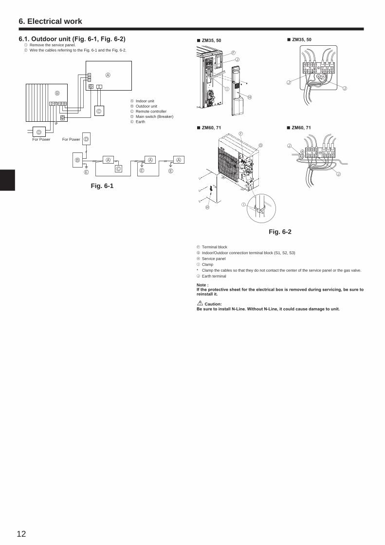
6.1. Outdoor unit (Fig. 6-1, Fig. 6-2) 1 Remove the service panel. 2 Wire the cables referring to the Fig. 6-1 and the Fig. 6-2.
C
Fig. 6-1
A Indoor unitB Outdoor unitC Remote controllerD Main switch (Breaker)E Earth
Fig. 6-2
A
B
D
D
AAAB
C EEE
For Power For Power
L N S1 S2 S3
J
J
FTerminal blockGIndoor/Outdoor connection terminal block (S1, S2, S3)HService panelIClamp* Clamp the cables so that they do not contact the center of the service panel or the gas valve.JEarth terminal
J
J
ZM35, 50
Note : If the protective sheet for the electrical box is removed during servicing, be sure to reinstall it.
Caution:Be sure to install N-Line. Without N-Line, it could cause damage to unit.
ZM60, 71F
G
HI
ZM35, 50
ZM60, 71
F
J
H
I
BH79D314H06_EN.indd 12 2017/02/10 8:46:55
S1
S2
S3
S1
S2
S3
13
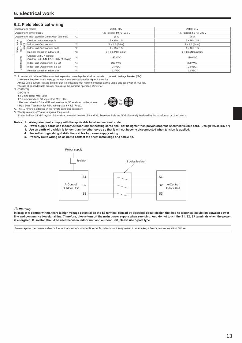
6.2. Field electrical wiringOutdoor unit model ZM35, 50V ZM60, 71VOutdoor unit power supply ~/N (single), 50 Hz, 230 V ~/N (single), 50 Hz, 230 VOutdoor unit input capacity Main switch (Breaker) *1 16 A 25 A
Wiri
ng W
ire
No.
× s
ize
(mm
²)
Outdoor unit power supply 3 × Min. 1.5 3 × Min. 2.5Indoor unit-Outdoor unit *2 3 × 1.5 (Polar) 3 × 1.5 (Polar)Indoor unit-Outdoor unit earth *2 1 × Min. 1.5 1 × Min. 1.5Remote controller-Indoor unit *3 2 × 0.3 (Non-polar) 2 × 0.3 (Non-polar)
Circ
uit r
atin
g Outdoor unit L-N (single)Outdoor unit L1-N, L2-N, L3-N (3 phase)
*4 230 VAC 230 VAC
Indoor unit-Outdoor unit S1-S2 *4 230 VAC 230 VACIndoor unit-Outdoor unit S2-S3 *4 24 VDC 24 VDCRemote controller-Indoor unit *4 12 VDC 12 VDC
*1. A breaker with at least 3.0 mm contact separation in each poles shall be provided. Use earth leakage breaker (NV). Make sure that the current leakage breaker is one compatible with higher harmonics. Always use a current leakage breaker that is compatible with higher harmonics as this unit is equipped with an inverter. The use of an inadequate breaker can cause the incorrect operation of inverter.*2. (ZM35-71) Max. 45 m If 2.5 mm2 used, Max. 50 m If 2.5 mm2 used and S3 separated, Max. 80 m
• Use one cable for S1 and S2 and another for S3 as shown in the picture.• Max. 50 m Total Max. for PEA. Wiring size 3 × 1.5 (Polar).
*3. The 10 m wire is attached in the remote controller accessory.*4. The figures are NOT always against the ground. S3 terminal has 24 VDC against S2 terminal. However between S3 and S1, these terminals are NOT electrically insulated by the transformer or other device.
Notes: 1. Wiring size must comply with the applicable local and national code. 2. Power supply cords and Indoor/Outdoor unit connecting cords shall not be lighter than polychloroprene sheathed flexible cord. (Design 60245 IEC 57) 3. Use an earth wire which is longer than the other cords so that it will not become disconnected when tension is applied. 4. Use self-extinguishing distribution cables for power supply wiring. 5. Properly route wiring so as not to contact the sheet metal edge or a screw tip.
A-Control Outdoor Unit
3 poles isolator
Power supply
Isolator
A-Control Indoor Unit
Warning:In case of A-control wiring, there is high voltage potential on the S3 terminal caused by electrical circuit design that has no electrical insulation between power line and communication signal line. Therefore, please turn off the main power supply when servicing. And do not touch the S1, S2, S3 terminals when the power is energized. If isolator should be used between indoor unit and outdoor unit, please use 3-pole type.
6. Electrical work
Never splice the power cable or the indoor-outdoor connection cable, otherwise it may result in a smoke, a fire or communication failure.
BH79D314H06_EN.indd 13 2017/02/10 8:46:55
14
7. Test run
7.1. Before test run After completing installation and the wiring and piping of the indoor and
outdoor units, check for refrigerant leakage, looseness in the power supply or control wiring, wrong polarity, and no disconnection of one phase in the supply.
Use a 500-volt megohmmeter to check that the resistance between the pow-er supply terminals and ground is at least 1 MΩ.
Do not carry out this test on the control wiring (low voltage circuit) termi-nals. Warning:
Do not use the air conditioner if the insulation resistance is less than 1 MΩ.
Insulation resistanceAfter installation or after the power source to the unit has been cut for an extended period, the insulation resistance will drop below 1 M" due to refrigerant accumulat-ing in the compressor. This is not a malfunction. Perform the following procedures.1. Remove the wires from the compressor and measure the insulation resistance of
the compressor.2. If the insulation resistance is below 1 M", the compressor is faulty or the resist-
ance dropped due the accumulation of refrigerant in the compressor.3. After connecting the wires to the compressor, the compressor will start to warm
up after power is supplied. After supplying power for the times indicated below, measure the insulation resistance again.
• The insulation resistance drops due to accumulation of refrigerant in the com-pressor. The resistance will rise above 1 M" after the compressor is warmed up for 12 hours.
(The time necessary to warm up the compressor varies according to atmos-pheric conditions and refrigerant accumulation.)
• To operate the compressor with refrigerant accumulated in the compressor, the compressor must be warmed up at least 12 hours to prevent breakdown.
4. If the insulation resistance rises above 1 M", the compressor is not faulty.
Caution:• The compressor will not operate unless the power supply phase connection
is correct.• Turn on the power at least 12 hours before starting operation.- Starting operation immediately after turning on the main power switch can result
in severe damage to internal parts. Keep the power switch turned on during the operational season.
The followings must be checked as well.• The outdoor unit is not faulty. LED1 and LED2 on the control board of the outdoor
unit flash when the outdoor unit is faulty.• Both the gas and liquid stop valves are completely open.• A protective sheet covers the surface of the DIP switch panel on the control board
of the outdoor unit. Remove the protective sheet to operate the DIP switches eas-ily.
7.2. Test run7.2.1. Using SW4 in outdoor unit
SW4-1 ONCooling operation
SW4-2 OFFSW4-1 ON
Heating operationSW4-2 ON
* After performing the test run, set SW4-1 to OFF.• After power is supplied, a small clicking noise may be heard from the inside of the
outdoor unit. The electronic expansion valve is opening and closing. The unit is not faulty.
• A few seconds after the compressor starts, a clanging noise may be heard from the inside of the outdoor unit. The noise is coming from the check valve due to the small difference in pressure in the pipes. The unit is not faulty.
The test run operation mode cannot be changed by DIP switch SW4-2 during the test run. (To change the test run operation mode during the test run, stop the test run by DIP switch SW4-1. After changing the test run operation mode, resume the test run by switch SW4-1.)
7.2.2. Using remote controllerRefer to the indoor unit installation manual.
Note :Occasionally, vapor that is made by the defrost operation may seem as if smoke come up from the outdoor unit.
BH79D314H06_EN.indd 14 2017/02/10 8:46:55
15
1 2 3 4 5 6
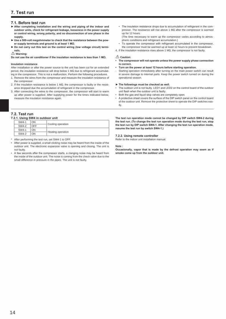
8.1. Low noise mode (on-site modification) (Fig. 8-1)By performing the following modification, operation noise of the outdoor unit can bereduced by about 3-4 dB.The low noise mode will be activated when a commercially available timer or thecontact input of an ON/OFF switch is added to the CNDM connector (option) on thecontrol board of the outdoor unit.• The ability varies according to the outdoor temperature and conditions, etc.1 Complete the circuit as shown when using the external input adapter
(PAC-SC36NA-E). (Option)2 SW7-1 (Outdoor unit control board): OFF3 SW1 ON: Low noise mode SW1 OFF: Normal operation
A Circuit diagram example (low noise mode)B On-site arrangementC External input adapter (PAC-SC36NA-E)X: Relay
D Outdoor unit control boardE Max. 10 mF Power supply for relay
8.3. Refrigerant collecting (pump down)Perform the following procedures to collect the refrigerant when moving the indoor unit or the outdoor unit.1 Supply power (circuit breaker). * When power is supplied, make sure that “CENTRALLY CONTROLLED” is not
displayed on the remote controller. If “CENTRALLY CONTROLLED” is dis-played, the refrigerant collecting (pump down) cannot be completed normally.
* Start-up of the indoor-outdoor communication takes about 3 minutes after the power (circuit breaker) is turned on. Start the pump-down operation 3 to 4 minutes after the power (circuit breaker) is turned ON.
2 After the liquid stop valve is closed, set the SWP switch on the control board of the outdoor unit to ON. The compressor (outdoor unit) and ventilators (indoor and outdoor units) start operating and refrigerant collecting operation begins. LED1 and LED2 on the control board of the outdoor unit are lit.
* Only set the SWP switch (push-button type) to ON if the unit is stopped. However, even if the unit is stopped and the SWP switch is set to ON less than 3 minutes after the compressor stops, the refrigerant collecting operation cannot be performed. Wait until compressor has been stopped for 3 minutes and then set the SWP switch to ON again.
* Set the refrigerant address using the DIP switch of the outdoor unit.1 Wiring from the Remote ControlThis wire is connected to TB5 (terminal board for remote controller) of the indoor unit (non-polar).2 When a Different Refrigerant System Grouping is Used.Up to 16 refrigerant systems can be controlled as one group using the slim MA remote controller.
Note:In single refrigerant system (twin/triple), there is no need of wiring 2.
A Outdoor unitB Indoor unitC Master remote controllerD Subordinate remote controllerE Standard 1:1 (Refrigerant address = 00)F Simultaneous twin (Refrigerant address = 01)G Simultaneous triple (Refrigerant address = 02)
E SW 1 - 3 ~ 6
F SW 1 - 3 ~ 6
G SW 1 - 3 ~ 6
A
Fig. 8-1
3 Because the unit automatically stops in about 2 to 3 minutes when the refrigerant collecting operation is completed (LED1 off, LED2 lit), be sure to quickly close the gas stop valve. If LED1 is lit and LED2 is off and the outdoor unit is stopped, refrig-erant collection is not properly performed. Open the liquid stop valve completely, and then repeat step 2 after 3 minutes have passed.
* If the refrigerant collecting operation has been completed normally (LED1 off, LED2 lit), the unit will remain stopped until the power supply is turned off.
4 Turn off the power supply (circuit breaker). * Note that when the extension piping is very long with large refrigerant amount,
it may not be possible to perform a pump-down operation. When performing the pump-down operation, make sure that the low pressure is lowered to near 0 MPa (gauge).
Warning:When pumping down the refrigerant, stop the compressor before disconnect-ing the refrigerant pipes. The compressor may burst if air etc. get into it.
9. System control (Fig. 9-1)
Fig. 9-1
SW1Function table
<SW1>
FunctionOperation according to
switch settingON OFF
SW1function settings
1 Compulsory de-frosting Start Normal
2 Error history clear Clear Normal3456
Refrigerant system address setting
Settings for outdoor unit addresses 0 to 15
TB1
A GFAA E
B B B B B B
DC
TB1 TB1
TB4
TB5
TB4
TB5
TB4 TB4
TB5
TB4 TB4
1
1
2
ON OFF
ON OFF
ON OFF
3 4 5 6
3 4 5 6
3 4 5 6
ON OFF
2
A Circuit diagram example (Demand function)B On-site arrangementX, Y: Relay
C External input adapter (PAC-SC36NA-E)D Outdoor unit control boardE Max. 10 mF Power supply for relay
8.2. Demand function (on-site modification) (Fig. 8-2)By performing the following modification, energy consumption can be reduced to 0–100% of the normal consumption.The demand function will be activated when a commercially available timer or thecontact input of an ON/OFF switch is added to the CNDM connector (option) on thecontrol board of the outdoor unit.1 Complete the circuit as shown when using the external input adapter
(PAC-SC36NA-E). (Option)2 By setting SW7-1 on the control board of the outdoor unit, the energy consump-
tion (compared to the normal consumption) can be limited as shown below.SW7-1 SW2 SW3 Energy consumption
Demand function ON
OFF OFF 100%ON OFF 75%ON ON 50%OFF ON 0% (Stop)
A
Fig. 8-2
8. Special functions
SW1
1
3
EB
F
CNDM
XX
SW2 SW3
1
3
CNDM
Y
XX Y
F
B E
C D
C D
10. Specifications
Outdoor model PUZ-ZM35VKA PUZ-ZM50VKA PUZ-ZM60VHA PUZ-ZM71VHAPower supply (V / Phase / Hz) 230 / Single / 50Dimensions (H × W × D) mm 630 × 809 × 300 943 × 950 × 330(+30)
Sound level *1Cooling
dB(A)44 44 47 47
Heating 46 46 49 49
*1 Measured under rated operation frequency.
Brown
Red
Orange
Brown
Red
Orange
BH79D314H06_EN.indd 15 2017/02/10 8:46:55
BH79D314H06 Printed in Japan
HEAD OFFICE: TOKYO BUILDING, 2-7-3, MARUNOUCHI, CHIYODA-KU, TOKYO 100-8310, JAPAN
This product is designed and intended for use in the residential,commercial and light-industrial environment.
Importer:
Mitsubishi Electric Europe B.V.Capronilaan 46, 1119 NS, Schiphol Rijk, The Netherlands
French Branch25, Boulevard des Bouvets, 92741 Nanterre Cedex, France
German BranchMitsubishi-Electric-Platz 1, 40882 Ratingen, Germany
Belgian BranchAutobaan 2, 8210 Loppem, Belgium
Irish BranchWestgate Business Park, Ballymount, Dublin 24, Ireland
Italian BranchCentro Direzionale Colleoni, Palazzo Sirio-Ingresso 1 Viale Colleoni 7, 20864 Agrate Brianza(MB), Italy
Norwegian BranchGneisveien 2D, 1914 Ytre Enebakk, Norway
Portuguese BranchAvda. do Forte, 10, 2799-514, Carnaxide, Lisbon, Portugal
Spanish BranchCarretera de Rubi 76-80 - Apdo. 420 08173 Sant Cugat del Valles (Barcelona), Spain
Scandinavian BranchHammarbacken 14, P.O. Box 750 SE-19127, Sollentuna, Sweden
UK BranchTravellers Lane, Hatfield, Herts., AL10 8XB, England, U.K.
Polish BranchKrakowska 50, PL-32-083 Balice, Poland
Please be sure to put the contact address/telephone number on this manual before handing it to the customer.
BH79D314H06_backcover.indd 4 2017/02/10 8:46:25


![h^< µ P u ] Z ( î ì í ô - info.usk-gifhorn.de · USK Zugmeisterschaft Finale und Sonderpokal 2018 11.10.2018 - 11.10.2019 Schützenheim Gifhorm ERGEBNISSE AUSWERTUNG ZM FINALE](https://static.fdocument.org/doc/165x107/5d63f85788c993c1628b83e4/h-p-u-z-i-i-i-o-infousk-usk-zugmeisterschaft-finale-und-sonderpokal.jpg)