Adiabatic Shear Localization || Shear Localization in Deep Geological Layers During Seismic Slip
28
10 Shear Localization in Deep Geological Layers During Seismic Slip Jean Sulem CERMES, Laboratoire Navier, Ecole des Ponts Paris Tech, IFSTTAR, Universite ´ Paris-Est, Marne-la-Valle ´e, France Nomenclature p pressure T temperature n porosity ρ density of the porous medium ρ f density of the saturating fluid σ n normal stress τ shear stress p pore fluid pressure ε volumetric strain γ shear strain ε p plastic volumetric strain γ p plastic shear strain ω c Cosserat rotation R Cosserat internal length G elastic shear modulus G c Cosserat elastic shear modulus K elastic bulk modulus of the porous medium K s bulk modulus of the solid matrix b Biot coefficient H plastic hardening modulus μ friction coefficient β dilatancy coefficient β f pore fluid compressibility λ f pore fluid thermal expansion coefficient β n pore volume compressibility β f pore volume thermal expansion β storage coefficient Λ undrained thermo-elastic pressurization coefficient k f permeability Adiabatic Shear Localization. DOI: http://dx.doi.org/10.1016/B978-0-08-097781-2.00010-1 © 2012 Elsevier Ltd. All rights reserved.
Transcript of Adiabatic Shear Localization || Shear Localization in Deep Geological Layers During Seismic Slip

10Shear Localization in DeepGeological Layers DuringSeismic Slip
Jean Sulem
CERMES, Laboratoire Navier, Ecole des Ponts Paris Tech, IFSTTAR,Universite Paris-Est, Marne-la-Vallee, France
Nomenclature
p pressure
T temperature
n porosity
ρ density of the porous medium
ρf density of the saturating fluid
σn normal stress
τ shear stress
p pore fluid pressure
ε volumetric strain
γ shear strain
εp plastic volumetric strain
γp plastic shear strain
ωc Cosserat rotation
R Cosserat internal length
G elastic shear modulus
Gc Cosserat elastic shear modulus
K elastic bulk modulus of the porous medium
Ks bulk modulus of the solid matrix
b Biot coefficient
H plastic hardening modulus
μ friction coefficient
β dilatancy coefficient
βf pore fluid compressibility
λf pore fluid thermal expansion coefficient
βn pore volume compressibility
βf pore volume thermal expansion
β�storage coefficient
Λ undrained thermo-elastic pressurization coefficient
kf permeability
Adiabatic Shear Localization. DOI: http://dx.doi.org/10.1016/B978-0-08-097781-2.00010-1
© 2012 Elsevier Ltd. All rights reserved.

chy hydraulic diffusivity
cth thermal diffusivity
ρC specific heat per unit volume of the material
ΔrH0T enthalpy change of the chemical reaction for calcite decomposition
Ea activation energy of the chemical reaction for calcite decomposition
10.1 Introduction
In the past 30 years, the study of earthquake mechanisms has emphasized the major
role of rock friction. Earthquakes appear to be the result of a frictional instability
and occur by sudden slippage along a pre-existing fault because the frictional resis-
tance to slip on the fault walls decreases with increasing slip, causing an accelera-
tion of sliding. Field observations of mature faults, i.e. faults that have experienced
a large slip, show a generally broad zone of damaged rock, but nevertheless suggest
that shear in individual earthquakes occurs in very narrow localized zones of a
few millimetres thick or even less. Field observations reveal that the fault material
inside the localized shear zone is a finely granulated gouge that has usually under-
gone mechano-chemical degradation (intense grain comminution, gelification,
decarbonation and dehydration reactions, melting) [1]. The actual thickness of the
zone over which the shear is localized is a key parameter for the evaluation of the
energy budget during earthquake rupture. It is generally estimated that more than
90% of the frictional work is converted into heat [2]. Thus, it is expected that
weakening mechanisms from thermal origin are of major importance. Fault zones
commonly exhibit the presence of fluid interacting with the rock. Recent theoretical
studies have emphasized the role of thermal pore fluid pressurization as an impor-
tant cause of slip weakening [3]. The principle of slip weakening by thermal pres-
surization is based on the fact that pore fluids trapped inside the fault zone are put
under pressure by shear heating, thus inducing a reduction of the effective mean
stress and of the shearing resistance of the fault plane [4�7]. This mechanism has
also been suggested for weakening in catastrophic landslides [8�15]. The presence
of clay material in fault zones also affects thermal pressurization as possible col-
lapse of the clay under thermal loading may activate fluid pressurization [7,16].
Thermo-poro-mechanical couplings due to shear heating can also be associated
with chemical effects such as dehydration of minerals or decomposition of carbo-
nates [17�20]. Such reactions induce two competing effects: a direct increase in
pore pressure because they release fluid in the system and a limit in temperature
increase because these reactions are endothermic so that part of the frictional heat
is actually absorbed in the chemical reactions.
In this chapter, we first present the thermo-poro-mechanical background used to
analyse the effect of pore fluid and temperature in the strain localization process as
the result of instability of undrained adiabatic shearing of a rock layer. In particu-
lar, we analyse the possibility of a selection of a preferred wavelength of the insta-
bility mode (i.e. the one corresponding to the fastest growth), which could control
the width of the localized zone. The undrained adiabatic limit is applicable as soon
400 Adiabatic Shear Localization

as the slip event is sufficiently rapid and the shear zone broad enough to effectively
preclude heat or fluid transfer as is the case during an earthquake. Then we will
consider a particular example of chemical couplings during seismic slip by taking
into account the possibility for some parts of the fault zone to reach the threshold
temperature at which mineral decomposition can be triggered.
10.2 Position of the Problem and Governing Equations
We consider a layer of saturated rock of thickness h that is sheared in plane strain
(Figure 10.1) in such a way that there is no extensional strain in the x-direction and dis-
placements ux, and uz of material points vary only with z (and time t). The stress state
in the layer is a shear stress τ and a normal stress σ in the y-direction. The only non-
zero strains, a shear strain γ and a normal strain ε, are related to the displacements by
γ5@ux@z
; ε5@uz@z
ð10:1Þ
Because the normal strains in the other directions are zero, the volumetric strain
is equal to ε.The equilibrium equations during quasi-static deformation reduce to
@τ@z
5 0;@σ@z
5 0 ð10:2Þ
so that the stresses must be spatially uniform and vary only with time during the
deformation.
10.2.1 Constitutive Equations
The rate thermo-poro elasto-plastic relationships for the rock layer are expressed as
_γ51
G_τ1 _γp; _ε5
1
Kð _σ2 b _pÞ2αs
_T 1 _εp ð10:3Þ
p,T
τ
σ
h
qhqf
z
x
uy(z,t)
ux(z,t)
Figure 10.1 Model of a deforming shear
band with heat and fluid fluxes.
401Shear Localization in Deep Geological Layers During Seismic Slip

where G and K are the elastic shear and bulk modulus, respectively, of the empty
porous solid, p is the pore pressure, T is the temperature, b is the Biot coefficient,
and αs is the thermal dilatation coefficient of the empty porous solid. The Biot
coefficient is related to the bulk modulus of the solid matrix Ks according to the
following equation:
b5 12K
Ks
ð10:4Þ
The rate of plastic deformation is written as [21]
_γp 51
Hð_τ2μð _σ2 _pÞÞ
_εp 5 β _γpð10:5Þ
where H(γp) is the plastic-hardening modulus and is related to the tangent modulus
Htan of the τ versus γ curve by (Figure 10.2)
Htan 5H
11H=Gð10:6Þ
and is either positive or negative according to whether τ versus γ curve is rising
(hardening) or falling (softening), although the falling portion may never be
observed as homogeneous deformation in a drained test. In Eq. (10.5), β is the
dilatancy coefficient.
1 + H/G
H
H + μβ/β*
1+ (H + μβ/β*)/G1
γ
τ
Drained
Undrained
1
Figure 10.2 Stress�strain curve for a
saturated rock in drained or undrained
conditions.
402 Adiabatic Shear Localization

10.2.2 Mass Balance Equation
Conservation of fluid mass is expressed by
@mf
@t52
@qf@z
ð10:7Þ
where mf is the total fluid mass per unit volume of porous medium (in the reference
state) and qf is the flux of fluid. The total fluid mass per unit volume of porous
medium is written as mf5 ρfn, where n is the pore volume fraction (Lagrangian
porosity) and ρf is the density of the saturating fluid. The left-hand side of
Eq. (10.7) is obtained by differentiating this product:
@mf
@t5 n
@ρf@t
1 ρf@n
@tð10:8Þ
The derivatives of the right-hand side of Eq. (10.8) are given by
@ρf@t
5 ρfβf
@p
@t2 ρfλf
@T
@tð10:9Þ
and
@n
@t5 nβn
@p
@t1 nλn
@T
@t1
@np
@tð10:10Þ
where βf 51ρf
@ρf@p
� �Tis the pore fluid compressibility, λf 52 1
ρf@ρfT
� �Pp
is the pore
fluid thermal-expansion coefficient, βn 51n
@n@p
� �Tis the pore volume compressibility
and λn 51n
@n@T
� �Pp
is the elastic thermal-expansion coefficient of the pore volume,
which is equal to the elastic thermal-expansion coefficient of the solid fraction,
λn5αs.
The expression of the pore volume compressibility is obtained from poro-elasticity
theory and is given by [3,22]
βn 51
n
1
K2
11 n
Ks
� �ð10:11Þ
In Eq. (10.10), @np
@t is the rate of plastic porosity change.
Using Eqs (10.2)�(10.4), the left-hand side of Eq. (10.7) is thus evaluated as
@mf
@t5 nρfðβn 1βfÞ
@p
@t2 ρfnðλf 2λnÞ
@T
@t1 ρf
@np
@tð10:12Þ
403Shear Localization in Deep Geological Layers During Seismic Slip

The flux term in Eq. (10.7) is evaluated assuming Darcy’s law for fluid flow
with viscosity ηf through a material with permeability kf:
qf 52ρfηf
kf@p
@zð10:13Þ
Substituting Eqs (10.12) and (10.13) into Eq. (10.7) gives the equation that gov-
erns the pore fluid production and diffusion:
@p
@t5 chy
@2p
@z21Λ
@T
@t2
1
β�@np
@tð10:14Þ
where
Λ5λf 2λn
βn 1βf
ð10:15Þ
is the thermo-elastic pressurization coefficient under undrained conditions [3]. This
coefficient is pressure and temperature dependent because the compressibility and
the thermal-expansion coefficients of the fluid vary with pressure and temperature
and also because the compressibility of the pore space of the rock can change with
the effective stress [22]. In Eq. (10.14), β�5 n(βn1 βf) is the storage capacity of
the rock and chy5 kf/(βηf) is the hydraulic diffusivity. For incompressible solid
phase and fluid, β�5 1/K.
If we assume that the solid matrix is plastically incompressible,
@np
@t5
@εp
@tð10:16Þ
10.2.3 Energy Balance Equation
Let EF be the rate of frictional heat produced during shearing. The equation of con-
servation of energy is expressed as
ρC@T
@t5EF 2
@qh@z
ð10:17Þ
where ρC is the specific heat per unit volume of the material in its reference state and qhis the heat flux. It is assumed here that all of the plastic work is converted into heat and,
thus, EF 5 τ _γp: The heat flux is related to the temperature gradient by Fourier’s law:
qh 52kT@T
@zð10:18Þ
404 Adiabatic Shear Localization

where kT is the thermal conductivity of the saturated material. Substituting
Eq. (10.18) into Eq. (10.19) gives the energy conservation equation
@T
@t5 cth
@2T
@z21
1
ρCτ _γp ð10:19Þ
where cth5 kT/ρC is the thermal diffusivity.
Undrained Adiabatic Limit
We assume that the drainage and the heat flux are prohibited at the boundaries of
the layer (qf5 0 and qh5 0). This corresponds to the situation when the slip event
is sufficiently rapid and the shear zone broad enough to effectively preclude heat or
fluid transfer as is the case during an earthquake or a landslide. We also assume
that the normal stress σ acting on the sheared layer is constant ( _σ5 0). From Eqs
(10.5), (10.14), (10.16) and (10.19), we obtain the following relationship between
the pore pressure rate and the shear stress rate:
_p5ΛτρC 2 β
β�
H2μ ΛτρC 2 β
β�
� � _τ ð10:20Þ
Substituting Eq. (10.20) into Eq. (10.3), we get
_γ51
G1
1
H1μβ=β� 2μΛτ=ρC
� �_τ ð10:21Þ
or
_τ5H1μβ=β� 2μΛτ=ρC
11ðH1μβ=β� 2μΛτ=ρCÞ=G
� �_γ ð10:22Þ
If we neglect the thermal effect (Λ5 0), the expression for dilatant hardening
effect as proposed by Rice [21] is retrieved (Figure 10.2):
_τ5H1μβ=β�
11ðH1μβ=β�Þ=G
� �_γ ð10:23Þ
Equation (10.22) has to be compared with the drained case for which
_τ5H
11H=G
� �_γ ð10:24Þ
405Shear Localization in Deep Geological Layers During Seismic Slip

For dilatant material (β. 0), we identify in Eq. (10.22) a hardening effect
due to dilatancy with the term μβ/β�and a thermal-softening effect with the
term 2μΛτ/ρC. When thermal softening prevails against strain hardening, plastic
localization in the form of adiabatic shear banding can occur.
10.3 Stability of Analysis of Undrained Adiabatic Shearingof a Rock Layer
We consider again the shearing of the layer while drainage and heat fluxes are pre-
vented at its boundaries. The pertinent variables are written in the form
γ5 γ0 1 ~γ; ε5 ε0 1 ~ε; σ5σ0 1 ~σ; τ5 τ0 1 ~τ; p5 p0 1 ~p; T 5 T0 1 ~T
ð10:25Þ
where the quantities γ0, τ0 and so on represent the solution of the last section for
homogeneous deformation, and ~γ; ~τ and so on are perturbation quantities.
Specifically, the layer is sheared by application of a monotonically increasing shear
stress τ05 τ0(t) to its boundary while the normal stress is held constant at σ0.From the equilibrium equation (10.2), the stress field is uniform within the layer,
and thus ~σ5 0 and ~τ5 0: This problem is similar to the one addressed by Rice
[21] with the introduction here of the thermal effect. From the conservation equa-
tions (10.14) and (10.19), and by keeping only the first-order terms, we get the
same type of rate equations for the perturbation terms
@ ~p
@t5 chy
@2 ~p
@z21Λ
@ ~T
@t2
1
β�@~εp
@t
@ ~T
@t5 cth
@2 ~T
@z21
1
ρCτ0
@ ~γp
@t
ð10:26Þ
with the following from the constitutive equation (10.5):
@ ~γp
@t5
μH
@ ~p
@t;
@~εp
@t5β
@ ~γp
@t5 β
μH
@ ~p
@tð10:27Þ
The spatial dependence of the perturbations is decomposed into Fourier modes
with wavelength λ. Perturbations of the form
~p5Pð0Þest cos 2πzλ
� �; ~T 5 Tð0Þest cos 2πz
λ
� �ð10:28Þ
406 Adiabatic Shear Localization

with λ5 h/n and n equal to an integer satisfy the zero heat and fluid flux boundary
conditions at y5 0, h. In Eq. (10.28), s is the growth coefficient in time of the per-
turbation. By substituting the perturbations field (Eq. (10.28)) into Eq. (10.26), we
obtain a homogeneous algebraic system for the coefficients P(0) and T(0). Thus, a
non-zero solution is possible only if the determinant of the coefficients vanishes:
det
s 11βμβ�H
0@
1A1 chy
2πλ
0@
1A2
2Λs
μρCH
τ0s 2 cth2πλ
0@
1A2
1 s
0@
1A
0BBBBBBB@
1CCCCCCCA
5 0 ð10:29Þ
The preceding condition yields a quadratic equation for the growth coefficient s:
ΛμρC
τ0 2βμβ� 2H
� �λ4s2 2 ðcth 1 chyÞH1
βμβ�
� �λ2s2 cthchyH5 0 ð10:30Þ
If a solution of Eq. (10.30) has a positive real part, then the corresponding per-
turbation grows exponentially in time.
If we do not consider the thermal effect, i.e. Λ5 0, the condition for stability is
simply H. 0. Thus, the result of Rice [21] is retrieved that undrained shearing is
stable only in those circumstances for which the underlying drained deformation
would be stable. This problem has also been examined by Vardoulakis [23,24] who
proposed a regularization of the mathematically ill-posed problem in the softening
regime by resorting to a second-grade extension of plasticity theory.
If we now take into account the thermal effect (Λ. 0), we observe that if
H. 0, the stability condition is
ΛμρC
τ0 ,βμβ� 1H ð10:31Þ
Consequently, the condition of stability of undrained adiabatic shearing is
H. 0 andΛμρC
τ0 ,βμβ� 1H ð10:32Þ
and the system is always unstable in the softening regime.
Obviously, this condition is more restrictive than the one for undrained shearing.
This result demonstrates the destabilizing effect of thermal fluid pressurization:
undrained adiabatic shearing of a material with positive strain hardening is
stable only when the thermal pressurization is not too high.
407Shear Localization in Deep Geological Layers During Seismic Slip

10.4 Wavelength Selection and Thickness of theShear Band
The stability analysis performed as described earlier for a classical Cauchy contin-
uum does not reveal any wavelength selection of the instability mode because
the change of sign from negative to positive values of the growth coefficient s
occurs for the same value of the hardening modulus independent of the considered
particular wavelength λ. Consequently, the width of the localized zone is actually
indeterminate. Moreover, we observe that at the onset of the instability, i.e. forΛμρC τ0 5
βμβ� 1H; there is a sharp transition from infinitely stable to infinitely
unstable behaviour, which indicates that the solution of the considered initial-value
problem does not exist and consequently that the corresponding problem is mathe-
matically ill-posed. The origin of this undesirable situation can be traced back to the
fact that conventional constitutive models do not contain material parameters with
dimension of length, so that the shear-band thickness (i.e. the extent of the plasti-
cally softening region) is undetermined. Rudnicki [25] proposed an ad hoc regulari-
zation by introducing a zone of finite thickness corresponding to a layer that has
already weakened due to past faulting. In doing so, inhomogeneous deformation is
prohibited over scales shorter than some prescribed length. Vardoulakis [24,26,27]
showed that by introducing viscous effects combined with second-gradient depen-
dency of the friction in strain may alleviate the ill-posedness of the problem. More
generally, it appears necessary to resort to continuum models with microstructure to
describe correctly localization phenomena. These generalized continua usually con-
tain additional kinematical degrees of freedom (Cosserat continuum) and/or higher
deformation gradients (higher grade continuum). Cosserat continua and higher grade
continua belong to a general class of constitutive models, which account for the
materials microstructure. The contemporary formulation of these models is based on
the work of Mindlin [28] and Germain [29,30]. Rotation gradients and higher veloc-
ity gradients introduce a material length scale into the problem, which, as already
mentioned, is necessary for the correct modelling of localization phenomena. This
idea was widely publicized by the paper of Muhlhaus and Vardoulakis [31] who
have resorted to concepts from Cosserat continuum mechanics to determine the
thickness of the shear band. Thus, by allowing both particle displacements and parti-
cle rotations, they accounted for the angularities of the grains and enriched the clas-
sical continuum with additional kinematic and static fields. For dry sand, they
obtained the shear-band thickness of about 16d50, where d50 is the mean grain diam-
eter. Considering the non-cohesive character of the cataclastic fault gouge inside the
slip zone, we follow the same idea and allow for additional rotational degrees of
freedom for the fault material within the frame of the Cosserat continuum theory.
10.4.1 Constitutive Equations
The incremental constitutive equations for the considered 2D Cosserat continuum
are derived from the Muhlhaus�Vardoulakis plasticity model. The main feature of
408 Adiabatic Shear Localization

the model is that a 2D flow theory of plasticity for granular media with Cosserat
microstructure can be derived by keeping the same definitions for the yield surface
and the plastic potential as in the classical theory and by generalizing appropriately
the stress and strain invariants involved in these definitions.
In a 2D Cosserat continuum, each material point has two translational degrees
of freedom (v1, v2) and one rotational degree of freedom ( _ωc). The four components
of the rate of the non-symmetric deformation tensor are given by
_ε11 5 @v1=@x1; _ε12 5 @v1=@x2 1 _ωc
_ε22 5 @v2=@x2; _ε21 5 @v2=@x1 1 _ωc ð10:33Þ
and the two components of the ‘curvature’ of the deformation rate (gradient of the
Cosserat rotation rate) are given by
_κ1 5 @ _ωc=@x1; _κ2 5 @ _ωc=@x2 ð10:34Þ
Besides the four components of the non-symmetric stress tensor σij, there are
two couple stresses, mk (k5 1,2). The convention used here for the stress tensor fol-
lows Vardoulakis and Sulem [32], i.e. the first index denotes the direction of the
force and the second index, the face with which a stress component is associated
(Figure 10.3).
As in classical small-strain plasticity theory, the deformation is decomposed into
elastic and plastic parts:
_εij 5 _εeij 1 _εpij; _κk 5 _κek 1 _κp
k ðk5 1; 2Þ ð10:35Þ
p,T
u1(x2, t)
u2(x2, t)m2
m1
ωc
σn
σ22σ21
σ12σ11
τ
x1
x2
qfqh
D
Figure 10.3 Cosserat stresses and couple stresses.
409Shear Localization in Deep Geological Layers During Seismic Slip

Moreover, the stress and the deformation are decomposed into spherical and
deviatoric parts:
σij 5 sij 1σkkδij=2_εij 5 _eij 1 _εkkδij=2
ð10:36Þ
where δij is the Kronecker delta.The generalized stress and strain invariants are utilized
σ5σii=2; τ5ffiffiffiffiffiffiffiffiffiffiffiffiffiffiffiffiffiffiffiffiffiffiffiffiffiffiffiffiffiffiffiffiffiffiffiffiffiffiffiffiffiffiffiffiffiffiffiffiffiffiffiffiffiffiffiffiffiffih1sijsij 1 h2sijsji 1 h3mkmk=R2
p_εp 5 _εpkk; _γp 5
ffiffiffiffiffiffiffiffiffiffiffiffiffiffiffiffiffiffiffiffiffiffiffiffiffiffiffiffiffiffiffiffiffiffiffiffiffiffiffiffiffiffiffiffiffiffiffiffiffiffiffiffiffiffiffiffig1 _e
pij _e
pij 1 g2 _e
pij _e
pji 1 g3R2 _κp
k _κpk
q ð10:37Þ
where {hi}5 {3/4,2 1/4,1} and {gi}5 {3/2,1/2,1} for the so-called static Cosserat
model, and R is the internal length of the material [32].
As in the previous section, we assume a Coulomb yield surface and plastic
potential
F5 τ2μðσ2 pÞ; Q5 τ2βðσ2 pÞ ð10:38Þ
where the mobilized friction and dilatancy coefficients μ and β, respectively, areonly functions of the accumulated plastic strain γp.
The strain-rate thermo-poro elasto-plastic relationships are formally unchanged and
are expressed by Eq. (10.3). The rate of plastic deformation is given by Eq. (10.5).
For the considered 2D Cosserat continuum and the configuration of Figure 10.3,
the local equilibrium equations are
@σ12
@x25 0
@σ22
@x25 0
@m
@x21σ21 2σ12 5 0
ð10:39Þ
with m5m2 and m1� 0. It is assumed that no couple stress is imposed at the
boundary. Prior to localization, the state of stress and strain is uniform and consid-
ering the couple-free boundary condition, the couple stress is identically zero in the
410 Adiabatic Shear Localization

sheared layer. Therefore, the rock layer behaves as a classical Cauchy continuum
prior to localization.
10.4.2 Stability of Analysis of Undrained Adiabatic Shearingfor a Cosserat Layer
The detailed analysis of the stability analysis of a Cosserat layer under shear is
presented in Ref. [33]. The main steps are recalled in the following. The small per-
turbations considered herein are defined as follows:
u1ðx2; tÞ5 u01ðx2; tÞ1 ~u1ðx2; tÞu2ðx2; tÞ5 u02ðx2; tÞ1 ~u2ðx2; tÞωcðx2; tÞ5ω0
cðx2; tÞ1 ~ωcðx2; tÞTðx2; tÞ5 T0ðx2; tÞ1 ~Tðx2; tÞpðx2; tÞ5 p0ðx2; tÞ1 ~pðx2; tÞ
ð10:40Þ
Dimensionless quantities are defined as
x5x1
R; z5
x2
R; ui 5
ui
R; i5 1; 2
p5p
σn
; σij 5σij
σn
; t5cth
R2t; T 5
Λσn
Tð10:41Þ
To simplify the notations, in the following and in the rest of the text, the line
over the symbols for the dimensionless variables is omitted: t � t; p � p; etc:The dimensionless form of the fluid mass balance equation (10.14) and the
energy conservation (10.19) is
@p
@t2
@T
@t2 η
@2p
@z21 δ
@γp
@t5 0
@T
@t2
@2T
@z22α
@γp
@t5 0
ð10:42Þ
where the dimensionless parameters α, δ and η are given by
α5Λτ0ρCσn
; δ5β
β�σn
; η5chy
cthð10:43Þ
411Shear Localization in Deep Geological Layers During Seismic Slip

and
@γ@t
p
51
2H
@σ12
@t1
@σ21
@t1μ
@σ011
@t1
@σ022
@t
0@
1A
0@
1A
H5H
σn
5 hσ0
σn
ð10:44Þ
The dimensionless form of the balance of linear momentum with inertia and
micro-inertia terms is as follows:
@σ12
@z2 I
@2u1@t2
5 0
@σ022
@z2
@p
@z2 I
@2u2@t2
5 0
@m
@z1 σ21 2σ12 2
1
2I@2ωc
@t25 0
ð10:45Þ
where the dimensionless inertia parameter is I5c2thρR2σn
: The moment of inertia of
the considered Cosserat continuum is ρR2/2 [32].
For the considered simple shear initial state of stress, the (dimensionless) incre-
mental thermo-poro elasto-plastic constitutive equations are given by
Δσ011
Δσ022
Δσ012
Δσ021
Δm
8>>>>>><>>>>>>:
9>>>>>>=>>>>>>;
5
a b c c 0
b a c c 0
f f d e 0
f f e d 0
0 0 0 0 g
0BBBBBB@
1CCCCCCA
Δγ11Δγ22Δγ12Δγ21Δκ
8>>>>>><>>>>>>:
9>>>>>>=>>>>>>;
2αs
ða1 bÞ=2ða1 bÞ=20
0
0
8>>>>>><>>>>>>:
9>>>>>>=>>>>>>;ΔT ð10:46Þ
where Δσ0ij 5Δσij 2Δpδij is the increment of dimensionless (Terzaghi) effective
stress:
Δγ11 5@Δu1
@x5 0; Δγ22 5
@Δu2
@z;
Δγ12 5@Δu1
@z1Δωc; Δγ21 5
@Δu2
@x2Δωc 52Δωc
Δκ5@Δωc
@z
ð10:47Þ
412 Adiabatic Shear Localization

and the dimensionless incremental constitutive coefficients are given by
a51
σn
K1G2βμK2
G1H1 βμK
0@
1A; b5
1
σn
K2G2βμK2
G1H1βμK
0@
1A
c51
σn
2GKβ
G1H1βμK
0@
1A; f 5
1
σn
2GKμ
G1H1βμK
0@
1A
d51
σn
G1Gc 2G2
G1H1βμK
0@
1A; e5
1
σn
G2Gc 2G2
G1H1βμK
0@
1A
g5G
σn
αs 5αs
σn
Λ
ð10:48Þ
Inserting the constitutive equations (10.46) in the governing equations (10.42)
and (10.45), we get
d@2 ~u1@z2
1 f@2 ~u2@z2
1ðd2 eÞ @ ~ωc
@z2 I
@2 ~u1@t2
5 0
c@2 ~u1@z2
1 a@2 ~u2@z2
2 I@2 ~u2@t2
2@ ~p
@z2αs
a1 b
2
@ ~T
@z5 0
ðd2 eÞ @ ~u1@z
1 g@2 ~ωc
@z21 2ðd2 eÞ @ ~ωc
@z2
1
2I@2ωc
@t25 0
δH
d1 e
21μc
0@
1A @2 ~u1
@z@t1
δH
f 1μa1 b
2
0@
1A @2 ~u2
@z@t2 η
@2 ~p
@z2
1@ ~p
@t2 11
δHμαs
a1 b
2
0@
1A @ ~T
@t5 0
2αH
d1 e
21μc
0@
1A @2 ~u1
@z@t2
αH
f 1μa1 b
2
0@
1A @2 ~u2
@z@t2
@2 ~T
@z2
1 11αHμαs
a1 b
2
0@
1A @ ~T
@t5 0
ð10:49Þ
413Shear Localization in Deep Geological Layers During Seismic Slip

The spatial dependence of the perturbations is again decomposed into Fourier
modes with wavelength λ. We consider perturbations of the form
~u1ðz; tÞ5U1 est sin
z
λ
0@1A
~u2ðz; tÞ5U2 est sin
z
λ
0@1A
~ωcðz; tÞ5Ω est cosz
λ
0@1A
~pðz; tÞ5Π est cosz
λ
0@1A
~T 5Θ est cosz
λ
0@1A
ð10:50Þ
By substituting the perturbation field (Eq. (10.50)) into the governing equations
(10.49), we obtain a homogeneous algebraic system for the coefficients {U1, U2, Ω,Θ, Π}. Thus, a non-zero solution is possible only if the determinant of the linear
system vanishes. The resulting characteristic polynomial equation is of degree 8 for
the growth coefficient s. As before, if a root has a positive real part, then the corre-
sponding perturbation grows exponentially in time.
10.4.3 Numerical Example
We refer here to a deep rock layer at a 7 km depth with the following values for
the initial state of stress and thermo-mechanical parameters:
ρ5 2500 kg=m3; σn 5 200 MPa; p5 66 MPa
μ5 0:5; β5 0 ðat great depthÞτ0 5μðσn 2 pÞ5 67 MPa
Λ5 0:5 MPa=�C; ρC5 2:8 MPa=�CG5 10; 000 MPa; K5 20; 000 MPa
Gc 5 5000 MPa; R5 0:01 mm
cth 5 1 mm2=s; chy 5 10 mm2=s; αs 5 2:53 1025=�C
ð10:51Þ
With these numerical values, it is obtained that there exists a critical value for
the hardening modulus hcr5 0.015 (i.e. in the hardening regime of the stress�strain
curve) such that for h$ hcr, all of the real roots of the polynomial equation are neg-
ative. For h, hcr, positive real roots exist. It is worth mentioning that from these
numerical computations, it is found that the root with the greatest positive real part
414 Adiabatic Shear Localization

is real (Figure 10.4). In other words, the instability mode with the fastest growth
coefficient is not a so-called flutter instability.
For a given value of the hardening modulus h, hcr, it is possible to plot the
greatest root (i.e. corresponding to the instability mode with the fastest growth in
time) as a function of the wavelength λ. This curve exhibits a maximum for
λ5λm so that a wavelength with the fastest growth in time appears (Figure 10.4).
In Figure 10.5, the selected wavelength is plotted versus the hardening modulus.
We observe that the selected wavelength tends to infinity for h ! h2cr: This selectedwavelength decreases with decreasing hardening modulus and reaches a minimum
(for h5 0.007, λm5 186.7) and then increases again and tends to infinity for h!0
(maximum shear stress). Muhlhaus and Vardoulakis [31] similarly obtained that at
bifurcation state, the shear-band thickness for dry granular materials is infinite and
decreases beyond the bifurcation state as the strain localization process evolves.
With R5 10 μm, which is an average grain size for a highly finely granulated
(ultra-cataclastic) fault core, the obtained minimum selected wavelength is about
2 mm, which is compatible with field observations of localized shear zones in
broader damaged fault zones.
0.0000
100
200
300
400
500
600
0.002 0.004 0.006 0.008
h
λ
0.010 0.012 0.014
Figure 10.5 Wavelength
selection.
Source: After Ref. [33].
Real part of polynomial roots for h = 0.0148
0.1
0.0
–0.1
Re(
s)
λ
–0.2
–0.30 200 400 600 800 1000 1200 1400
Figure 10.4 Real part of the
roots of the characteristic
equation (growth coefficient)
for h, hcr. The red, dashed
curves represent the real part
of the roots that are complex
(non-zero imaginary part),
while the thick, black curves
depict the real roots (zero
imaginary part). (For
interpretation of the references
to color in this figure legend,
the reader is referred to the
web version of this book.)
Source: After Ref. [33].
415Shear Localization in Deep Geological Layers During Seismic Slip

It is important to emphasize that the wavelength selection is not obtained if
Cosserat microstructure is not considered in the analysis. The critical hardening
modulus for instability is unchanged (hcr5 0.015), but the growth coefficient tends
to infinity for the infinitely small wavelength limit, which indicates that the con-
sidered problem is mathematically ill-posed. Moreover, it should be mentioned
that even if a Cosserat microstructure is considered, the mathematical problem
remains ill-posed without the inertia terms. The main point is that the inertia
terms remedy the ill-posedness of the mathematical problem, resulting in a finite
growth coefficient for the instability.
10.5 Effect of Chemical Couplings During RapidFault Shearing
In the preceding analysis, we have emphasized the role of shear heating and
fluid pressurization. The underlying assumption was that no fluid is produced
or consumed during seismic slip. There is, however, growing evidence that
temperature-induced decomposition of minerals may be a significant source of
fluids in faulted rocks, which may enhance the generation of pore-pressure excess.
This production of fluid is in competition with the change of porosity induced
by the reduction of solid volume during mineral decomposition. Obviously, the
competing effects of temperature rise (due to shear heating), thermal fluid pressuri-
zation, mineral decomposition and porosity/permeability increase induce strong
non-linearities in the problem of pore pressure and temperature evolution of a rap-
idly sheared fault zone. The kinetics of the chemical reaction of mineral decompo-
sition is also a major factor that competes with heat- and fluid-diffusion processes.
The endothermic character of the mineral decomposition reactions also plays a role
in the energy balance of the system. Therefore, the effect of thermal mineral
decomposition brings a very interesting chemical coupling to the problem under
consideration.
As an example, in this section, we will focus on the kinetics of chemical decom-
position of calcite (decarbonation) CaCO3!CaO1CO2, which is triggered when
the temperature reaches about 700�C. Carbonates are present in every fault zone
from the ductile�brittle transition (B15 km) to the subsurface, and there is evi-
dence of CO2 release in several active crustal faults. In the Corinth rift (Greece),
e.g. chemical analysis of water springs near the seismogenic Heliki and Aegion
faults revealed an anomalously high content of dissolved CO2 compared with the
regional values [34]. The surface trace of the San Andreas Fault also displays a positive
anomaly of CO2 fluxes [35], and this CO2 comes from a shallow source, not from
the mantle [36]. Moreover, there is growing evidence that CO2 release coincides
with seismic slip in crustal faults, active and/or exhumed. In the vicinity of the
Nojima fault (Japan), Sato and Takahashi [37] reported that the HCO32 concentration
of springs increased by 30 wt% immediately after the 1995 Kobe earthquake. This
carbon discharge, together with other co-seismic geochemical anomalies, decreased
416 Adiabatic Shear Localization

gradually to normal values in the following 10 months. A micro-infrared analysis of
exhumed pseudotachylites (i.e. friction-induced melts produced by seismic slip)
from the Nojima fault revealed that shear melting destroyed the carbonates within
the fault zone and released CO2, thus providing an explanation to the co-seismic
CO2 spikes in springs [38]. The quantity of CO2 released by friction melting during
the 1995 Kobe earthquake was evaluated as 1.8�3.43 103 tons. As for the San
Andreas Fault, the carbon isotopic signature of springs and fault rocks from Nojima
is consistent with a decomposition of biogenic carbonates, not from a mantle origin
[39,40]. In the Central Apennines, Italiano et al. [41] also reported enhanced fluxes
of crustal CO2 (i.e. not from the mantle) during the 1997�1998 seismic crisis of
major faults and proposed that co-seismic decarbonation was responsible for the
CO2 emission. Recent studies of the Chelungpu Fault (Taiwan) responsible for
the 1999 ChiChi earthquake also showed that the fault core was depleted in carbon
relative to the damage zone, and the depletion was attributed to decarbonation
induced by frictional heat [42,43]. In addition, recent high-velocity friction experi-
ments on Carrara marble have shown that thermal decomposition of calcite due
to frictional heating induces a pronounced fault weakening [44]. The production of
co-seismic CO2 is therefore attested by various field and experimental techniques,
thus making the thermal decomposition of carbonates an important additional
mechanism to be investigated among possible fault-weakening processes as recently
proposed by Sulem and Famin [19].
10.5.1 Modelling
The rate of emitted CO2 is evaluated using the kinetics of the chemical reaction of
calcite thermal decomposition:
CaCO3 ! CaO1CO2 ð10:52Þ
The reacted fraction, α (0#α# 1; α5 1 if the entire substance is reacted), is
expressed by the Arrhenius equation [45]:
@α@t
5 f ðαÞA exp 2Ea
RT
� �ð10:53Þ
where f(α) is a kinetic function determined by the reaction mechanism, A is a con-
stant (pre-exponential term of the Arrhenius law), Ea is the activation energy of the
reaction and R is the gas constant (8.31447 J/K/mol). For calcite decomposition,
Ea5 319,000 J/mol and A5 2.953 1015 s21 [46].
Thus, the mass of emitted CO2 (per unit volume) is expressed as
@md
@t5χρCaCO3
ð12 nÞA exp 2Ea
RT
� �ð10:54Þ
417Shear Localization in Deep Geological Layers During Seismic Slip

where χ is the ratio between the molar mass MCO2of CO2 (44 g/mol) and the molar
mass MCaCO3of calcite (100 g/mol) if we assume that the total amount of calcite
can be decomposed. The corresponding change of porosity due to the decomposi-
tion of the solid phase is expressed as
@nd@t
521
ρCaCO3
@mCaCO3
@t2
1
ρCaCO
@mCaO
@t5
1
ρCaCO3
MCaCO3
MCO2
21
ρCaCO
MCaO
MCO2
!@md
@t
ð10:55Þ
where ρCaCO3(resp. ρCaO) and MCaCO3
(resp. MCaO) are the density and the molar
mass of CaCO3 (resp. CaO). The heat for calcite decomposition is calculated by
EC 5ΔrH
0T
χMCaCO3
@md
@tð10:56Þ
where ΔrH0T is the enthalpy change of the reaction (i.e. the energy consumed by
the reaction), which for calcite decomposition is equal to the activation energy Ea
in the isobaric mode [19].
Thus, the coupled system of production/diffusion equations (Eqs (10.14) and
(10.19)) are modified as:
@p
@t5 chy
@2p
@z21Λ
@T
@t2
1
β�@np
@t1
12 ρfζ=ρCaCO3
β�ρf
@md
@t
@T
@t5 cth
@2T
@z21
1
ρCτ _γp 2
ð12 nÞρC
ΔrH0T
MCaCO3
ρCaCO3A exp 2
Ea
RT
0@
1A ð10:57Þ
where ζ5 MCaCO3
MCO2
2ρCaCO3ρCaCO
MCaO
MCO2
: With MCaCO35 100 g=mol; MCaO5 56 g/mol,
MCO25 44 g=mol; ρCaCO3
5 2:71 g=cm3 and ρCaO 5 3:35 g=cm3; ζ5 1.24.
10.5.2 Numerical Example
For the pore pressure and temperature range considered here for which the
decarbonation of CO2 is active (T. 700�C, Pp. 70 MPa), water and carbon
dioxide are in a supercritical state. They are miscible, and their compressibility,
viscosity, density and thermal-expansion coefficient are nearly equal. Thus, it is
assumed in the computations that the fault zone is saturated with a unique fluid
and with the thermodynamical properties of water.
The decomposition of carbonate can induce substantial change in the porosity of
the rock, which affects the permeability. It is known that there is no unique
418 Adiabatic Shear Localization

relationship between porosity and permeability applicable to all porous media and that
the geological evolution process of the pore space influences the permeability�porosity relationship. The commonly used cubic Carman Kozeny permeability law
is assumed here to take into account the effect of porosity change due to mineral
decomposition on the permeability of the rock:
kf 5 kf012 n0
12n
� �2n
n0
� �3ð10:58Þ
where kf0 is the reference permeability corresponding to the reference porosity n0.
The assumed permeability law has a strong effect on the numerical results, and
there is a need for experimental data on permeability changes resulting from the
particular process of carbonate decomposition.
The initial porosity of the rock is taken to be equal to 0.03. The recent high-velocity
shear experiments on Carrara marble of Han et al. [44] have shown that the friction
coefficient f decreases rapidly to values as low as 0.06 due to the thermal decompo-
sition of calcite induced by frictional heating. Here, we take f5 0.1.
We assume here that the initial permeability of the intact medium is
kf5 10218 m2.
The computed results are presented in Figure 10.6. The evolution in time of the
temperature and the pore pressure in the centre of the band is plotted in
Figure 10.6A. Considering the constant slip velocity of 1 m/s, this graph can also
be seen as the evolution of temperature and pore pressure with accumulated slip.
The corresponding shear stress is plotted in Figure 10.6B. These results show the
coupling effect of heat, which induces first a pore pressure increase. When the
decomposition of the carbonate rock begins at about 700�C, the temperature
increase is drastically slowed due to the energy consumed in the endothermic
chemical reaction. Two competing effects act on the evolution of the pore pressure:
on the one hand, the production of CO2 induces an additional fluid mass and thus a
pressurization of the pore fluid; on the other hand, the increase of porosity due to
the solid decomposition induces an increase of the permeability of the medium,
which limits the pressurization. The pore pressure in the centre of the band exhibits
a maximum of about 145 MPa, which does not exceed the total normal stress acting
(180 MPa) on the band so full liquefaction is not reached. As mentioned earlier,
through the friction law, the shear stress is related to the mean effective stress
inside the band (Figure 10.6B). Consequently, the shear stress decreases rapidly
during initial pressurization and then increases again. Thus, the mineral decomposi-
tion of the rock can be seen as a mechanism of fault weakening in a first stage and
then fault re-strengthening in a second stage.
The accumulated mass per unit area of the fault plane of emitted CO2 is plotted
on Figure 10.6C. After 1 s, the temperature reaches a quasi-constant state, and the
production rate is almost constant. These results show that the mass of emitted CO2
after 2 s is about 0.018 g/cm2. The corresponding rate of emitted CO2 is about
419Shear Localization in Deep Geological Layers During Seismic Slip

180 t/s/km2 of the fault zone. The corresponding solid mass change is shown
through the evolution of the porosity in the centre of the shear band
(Figure 10.6D).
The temperature field around the centre of the band is shown in Figure 10.7 for
t5 2 s with the corresponding value of the porosity. These plots show that the tem-
perature increase is localized in the central zone of the band. The porosity is
affected only in zones where the temperature exceeds 700�C, which for the compu-
tation considered corresponds to a width of about 4 mm.
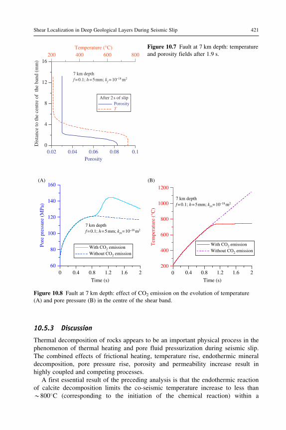
The effect of mineral decomposition is also shown in Figure 10.8 where the
results of the preceding computation are compared to the ones obtained without
CO2 emission. In this latter case, only thermal pressurization occurs. If no mineral
decomposition occurs, the pore pressure increase is slower, and for the parameters
considered, the maximum pore pressure is about 120 MPa. Consequently, the tem-
perature increase is much stronger, and melting of the rock can eventually occur
(the melting temperature is about 1600�C for calcite).
0 0.4 0.8 1.2 1.6 2
Time (s)
0 0.4 0.8 1.2 1.6 2
Time (s)
0 0.4 0.8 1.2 1.6 2
Time (s)
0 0.4 0.8 1.2 1.6 2
Time (s)
200
400
600
800
Tem
pera
ture
(°C
)
200
400
600
800
Tem
pera
ture
(°C
)
60
80
100
120
140
160
TPp Pp
τ
7 km depthf=0.1; kf0=10–18 m2
h=5mm
7 km depthf=0.1; kf0=10–18 m2
h=5mm
7 km depthf=0.1; kf0=10–18 m2
h=5mm
7 km depthf=0.1; kf0=10–18 m2
h=5mm
(A) (B)
(C) (D)
2
4
6
8
10
12
Shea
r st
ress
(M
Pa)
60
80
100
120
140
160
Pore pressure (MPa)
Pore pressure (MPa)
0
0.004
0.008
0.012
0.016
0.02M
ass of emitted C
O2 per unit area (g/cm
2)
Tmd
200
400
600
800T
empe
ratu
re (
°C)
0.02
0.04
0.06
0.08
0.1
Porosity
TPorosity
Figure 10.6 Fault at 7 km depth: (A) evolution of temperature and pore pressure in the
centre of the shear band, (B) evolution of the shear stress, (C) evolution of the mass of
emitted CO2 and (D) evolution of the porosity in the centre of the band.
420 Adiabatic Shear Localization
10.5.3 Discussion
Thermal decomposition of rocks appears to be an important physical process in the
phenomenon of thermal heating and pore fluid pressurization during seismic slip.
The combined effects of frictional heating, temperature rise, endothermic mineral
decomposition, pore pressure rise, porosity and permeability increase result in
highly coupled and competing processes.
A first essential result of the preceding analysis is that the endothermic reaction
of calcite decomposition limits the co-seismic temperature increase to less than
B800�C (corresponding to the initiation of the chemical reaction) within a
0.02 0.04 0.06 0.08 0.1Porosity
0
4
8
12
16
Dis
tanc
e to
the
cent
re o
f th
e ba
nd (
mm
)
200 400 600 800Temperature (°C)
After 2 s of slipPorosityT
7 km depthf=0.1; h=5mm; kf =10–18 m2
Figure 10.7 Fault at 7 km depth: temperature
and porosity fields after 1.9 s.
0 0.4 0.8 1.2 1.6 2
Time (s)0 0.4 0.8 1.2 1.6 2
Time (s)
60
80
100
120
140
160
Pore
pre
ssur
e (M
Pa)
200
400
600
800
1000
1200
Tem
pera
ture
(°C
)
With CO2 emissionWithout CO2 emission
With CO2 emission
(A) (B)
Without CO2 emission
7 km depthf=0.1; h=5mm; kf0=10–18 m2
7 km depthf=0.1; h=5mm; kf0=10–18 m2
Figure 10.8 Fault at 7 km depth: effect of CO2 emission on the evolution of temperature
(A) and pore pressure (B) in the centre of the shear band.
421Shear Localization in Deep Geological Layers During Seismic Slip

carbonate shear band under rapid slip. Decarbonation is only one of the possible
thermal reactions of mineral decomposition. Phyllosilicates are common secondary
minerals in faults, and their thermal dehydration is also endothermic. Therefore, it
is likely that the reaction-induced temperature limitation obtained in our model
may apply qualitatively to most fault zones. In this case, mature faults with a long
history of slip and a large cumulated displacement are likely to be more prone to
reaction-induced temperature limitation than recent faults because of their larger
content of volatile-rich secondary minerals. This would provide another explana-
tion for the notorious absence of a positive heat flow anomaly on active crustal
faults such as San Andreas [47]: a large part of the heat produced by friction would
be consumed by endothermic reactions. Another consequence is that friction melt-
ing is hampered by endothermic calcite decomposition in carbonate fault rocks and
probably in other faults containing a sufficiently high proportion of volatile-rich
secondary minerals. This is consistent with the relative scarcity of pseudotachylytes
in mature faults.
The second essential implication of the preceding analysis is that decarbonation
is a source of CO2 that significantly increases the slip-weakening effect of thermal
pressurization. The pore fluid pressure exhibits an initial phase of increase due to
thermal pressurization, then a sudden acceleration of pore pressure generated when
solid decomposition is activated. However, the increase of permeability limits the
pore pressure so that it reaches a maximum and then decreases. The numerical
results reproduce this pore pressure pulse and the initial fault weakening followed
by a re-strengthening of the shear stress.
10.6 Conclusion
In the first part of this chapter, we have analysed the undrained adiabatic shearing
of a saturated rock layer and shown the destabilizing effect of shear heating.
Instability can occur even in the hardening regime of the underlying drained
stress�strain response if dilatant hardening cannot compensate for the thermal
pressurization of the pore fluid. This result confirms that thermal effects play a
major role in the formation and evolution of the localized zone. A remarkable
result is that if we do not take into account the effect of microstructure and micro-
inertia, the underlying mathematical problem is ill-posed, i.e. for a hardening mod-
ulus lower than the critical hardening modulus at instability, the growth coefficient
of the instability is infinite. The complete dynamic analysis for a Cosserat contin-
uum leads to a wavelength selection of the instability mode as the growth coeffi-
cient in time is maximum and finite for a particular wavelength. The selected
wavelength is compatible with observed shear-band thickness in fault zones.
In the second part of the chapter, we analysed the effect of temperature-induced
mineral decomposition as it is a major slip-weakening process. Such chemical reac-
tions induce two competing effects: a direct increase in pore pressure because they
release fluid and a limit to the temperature increase because part of the frictional
422 Adiabatic Shear Localization

heat is absorbed in the endothermic reactions. The combined effects of frictional
heating, temperature rise, endothermic mineral decomposition, pore pressure rise,
porosity and permeability increase result in highly coupled and competing
processes.
In this chapter, we have emphasized the weakening effects of thermal pressuri-
zation and thermal decomposition of minerals. However, other important weaken-
ing mechanisms could also be included in the modelling. Flash heating and shear
weakening of frictional micro-asperity contacts is a mechanism that has been first
proposed for dry-metal friction and recently been applied to rock friction [3,48].
From the microscopic point of view, the contact between two rough surfaces is
effective on micro-asperities with an area that is much smaller than the nominal
contact area. The stresses supported by these asperities are much higher than the
macroscopic applied stresses so that the local rate of heat production and conse-
quently the local temperature rise during sliding is large and may be sufficient to
activate thermal weakening of the contacts. Other mechanisms responsible for fault
lubrication involve a number of physicochemical processes [1], such as the lubrica-
tion of the contact zone with the formation of silica gels [49] or the production of
very fine particles with nanometric size [50], and also the formation of a molten
layer along the sliding interface that also lubricates the contact zone and reduces
the friction resistance
Acknowledgements
The author wishes to recall the memory of Ioannis Vardoulakis as recognition for an inspir-
ing collaboration and a deep friendship. He gratefully acknowledges the fruitful collaboration
with N. Brantut, V. Famin, A. Schubnel, I. Stefanou and E. Veveakis. He also thanks J. Rice
for inspiring discussions.
References
1. Di Toro, G., Han, R., Hirose, T., De Paola, N., Nielsen, S., Mizoguchi, K., Ferri, F.,
Cocco, M., and Shimamoto, T. (2011). Fault lubrication during earthquakes, Nature 471,
494�498.
2. Cocco, M., Spudich, P., and Tinti, E. (2006). On the mechanical work absorbed on
faults during earthquake ruptures. In “Radiated Energy and the Physics of Faulting,” R.
Abercrombie et al. (Eds.), Geophysical Monograph Series, 170, pp. 237�254, AGU,
Washington, DC.
3. Rice, J. R. (2006). Heating and weakening of faults during earth-quake slip, Journal of
Geophysical Research 111, B05311.
4. Lachenbruch, A. H. (1980). Frictional heating, fluid pressure and the resistance to fault
motion, Journal of Geophysical Research 85, 6097�6112.
5. Mase, C. W. and Smith, L. (1985). Pore-fluid pressures and frictional heating on a fault
surface, Pure and Applied Geophysics 122, 583�607.
423Shear Localization in Deep Geological Layers During Seismic Slip

6. Sulem, J., Vardoulakis, I., Ouffroukh, H., and Perdikatsis, V. (2005). Thermo-poro-
mechanical properties of the Aigion fault clayey gouge � application to the analysis of
shear heating and fluid pressurization, Soils and Foundations 45(2), 97�108.
7. Sulem, J., Lazar, P., and Vardoulakis, I. (2007). Thermo-poro-mechanical properties
of clayey gouge and application to rapid fault shearing, International Journal of
Numerical and Analytical Methods in Geomechanics 31(3), 523�540.
8. Habib, P. (1967). Sur un mode de glissement des massifs rocheux, Comptes Rendus a
l’Academie des Sciences, Paris 264, 151�153.
9. Habib, P. (1976). Production of gaseous pore pressure during rock slides, Rock
Mechanics 7, 193�197.
10. Anderson, D. L. (1980). An earthquake induced heat mechanism to explain the loss of
strength of large rock and earth slides. In “Engineering for Protection from Natural
Disasters” P. Karasudhi et al. (Eds.), pp. 569�580, Wiley, New York, NY.
11. Voight, B. and Faust, C. (1982). Frictional heat and strength loss in some rapid
landslides, Geotechnique 32, 43�54.
12. Vardoulakis, I. (2002). Dynamic thermo-poro-mechanical analysis of catastrophic
landslides, Geotechnique 52(3), 157�171.
13. Goren, L. and Aharonov, E. (2007). Long runout landslides: the role of frictional
heating and hydraulic diffusivity, Geophysical Research Letters 34, L07301.
14. Veveakis, E., Vardoulakis, I., and Di Toro, G. (2007). Thermoporomechanics of
creeping landslides: the 1963 Vaiont slide, northern Italy, Journal of Geophysical
Research 112, F03026.
15. Pinyol, N. and Alonso, E. (2010). Criteria for rapid sliding. II. Thermo-hydro-mechanical
and scale effects in Vaiont case, Engineering Geology 114, 211�227.
16. Sulem, J., Vardoulakis, I., Ouffroukh, H., Boulon, M., and Hans, J. (2004).
Experimental characterization of the thermo-poro-mechanical properties of the Aegion
fault gouge, Comptes Rendus Geosciences 336(4�5), 455�466.
17. Brantut, N., Schubnel, A., Corvisier, J., and Sarout, J. (2010). Thermochemical pressurization
of faults during coseismic slip, Journal of Geophysical Research 115, B05314.
18. Brantut, N., Sulem, J., and Schubnel, A. (2011). Effect of dehydration reactions
on earthquake nucleation: stable sliding, slow transients and unstable slip, Journal of
Geophysical Research 116, B05304.
19. Sulem, J. and Famin, V. (2009). Thermal decomposition of carbonates in fault zones:
slip-weakening and temperature-limiting effects, Journal of Geophysical Research 114,
B03309.
20. Veveakis, E., Alevizos, S., and Vardoulakis, I. (2010). Chemical reaction capping of
thermal instabilities during shear of frictional faults, Journal of Mechanics and Physics
of Solids 58, 1175�1194.
21. Rice, J. R. (1975). On the stability of dilatant hardening for saturated rock masses,
Journal of Geophysical Research 80(11), 1531�1536.
22. Ghabezloo, S. and Sulem, J. (2009). Stress dependent thermal pressurization of a fluid-
saturated rock, Rock Mechanics and Rock Engineering 42, 1�24.
23. Vardoulakis, I. (1996). Deformation of water-saturated sand. I. Uniform undrained
deformation and shear banding, Geotechnique 46(3), 441�456.
24. Vardoulakis, I. (1996). Deformation of water-saturated sand. II. Effect of pore water
flow and shear banding, Geotechnique 46(3), 457�472.
25. Rudnicki, J. W. (1984). Effects of dilatant hardening on the development of concen-
trated shear deformation in fissured rock masses, Journal of Geophysical Research 89
(B11), 9259�9270.
424 Adiabatic Shear Localization

26. Vardoulakis, I. (1985). Stability and bifurcation of undrained, plane rectilinear deforma-
tions on water-saturated granular soils, International Journal of Numerical and
Analytical Methods in Geomechanics 9, 339�414.
27. Vardoulakis, I. (1986). Dynamic stability of undrained simple shear on water-saturated
granular soils, International Journal of Numerical and Analytical Methods in
Geomechanics 10, 177�190.
28. Mindlin, R. (1964). Micro-structure in linear elasticity, Archive for Rational Mechanics
and Analysis 16, 51�78.
29. Germain, P. (1973). La methode des puissances virtuelle en mecanique des milieux conti-
nus. Premiere partie: theorie du second gradient, Journal de Mecanique 12, 235�274.
30. Germain, P. (1973). The method of virtual power in continuum mechanics. Part 2:
Microstructure, SIAM Journal of Applied Mathematics 25, 556�575.
31. Muhlhaus, H.-B., and Vardoulakis, I. (1987). The thickness of shear bands in granular
materials, Geotechnique 37, 271�283.
32. Vardoulakis, I. and Sulem, J. (1995). Bifurcation Analysis in Geomechanics, Blackie
Academic and Professional, Glasgow.
33. Sulem, J., Stefanou, I., and Veveakis, E. (2011). Stability analysis of undrained adiabatic
shearing of a rock layer with Cosserat microstructure, Granular Matter 13, 261�268.
34. Pizzino, L., Quattrochi, F., Cinti, D., and Galli, G. (2004). Fluid geochemistry along the
Eliki and Aigion seismogenic segments (Gulf of Corinth, Greece), Comptes Rendus
Geosciences 336(4�5), 367�374.
35. Lewicki, J. L. and Brantley, S. L. (2000). CO2 degassing along the San Andreas fault,
Parkfield, California, Geophysical Research Letters 27(1), 5�8.
36. Lewicki, J. L., Evans, W. C., Hilley, G. E., Sorey, M. L., Rogie, J. D., and Brantley,
S. L. (2003). Shallow soil CO2 flow along the San Andreas and Calaveras faults,
California, Journal of Geophysical Research 108(B4), 2187.
37. Sato, T. and Takahashi, M. (1997). Geochemical changes in anomalously discharged
groundwater in Awaji Island after the 1995 Kobe earthquake, Chikyukagaku 31, 89�98.
38. Famin, V., Nakashima, S., Boullier, A.-M., Fujimoto, K., and Hirono, T. (2008).
Earthquake produce carbon dioxide in crustal faults, Earth and Planetary Science
Letters 265(3�4), 487�497.
39. Arai, T., Tsukahara, H., and Morikiyo, T. (2003). Sealing process with calcite in the
Nojima active fault zone revealed from isotope analysis of calcite, Journal of
Geography 112(6), 915�925.
40. Lin, A., Tanaka, N., Ueda, S., and Satish-Kumar, M. (2003). Repeated coseismic
infiltration of meteoric and seawater into deep fault zones: a case study of the Nojima
fault zone, Japan, Chemical Geology 202(1�2), 139�153.
41. Italiano, F., Martinelli, G., and Plescia, P. (2008). CO2 degassing over seismic areas:
the role of mechano-chemical production at the study case of central Apennines, Pure
and Applied Geophysics 165, 75�94.
42. Hirono, T., Ikehara, M., Otsuki, K., Mishima, T., Sakaguchi, M., Soh, W., Omori, M.,
Lin, W., Yeh, E., Tanikawa, W., and Wang, C. Y. (2006). Evidence of frictional
melting from disk-shaped black material, discovered within the Taiwan Chelungpu fault
system, Geophysical Research Letters 33, L19311.
43. Hirono, T., Yokohama, T., Hamada, Y., Tanikawa, W., Mishima, T., Ikehara, M.,
Famin, V., Tanimizu, M., Lin, W., Soh, W., and Song, S.-R. (2007). A chemical kinetic
approach to estimate dynamic shear stress during the 1999 Taiwan Chi-Chi earthquake,
Geophysical Research Letters 34, L19308.
425Shear Localization in Deep Geological Layers During Seismic Slip

44. Han, R., Shimamoto, T., Hirose, T., Ree, J.-H., and Ando, J. (2007). Ultralow friction
of carbonate faults caused by thermal decomposition, Science 316, 878�881.
45. L’vov, B. V. (2002). Mechanism and kinetics of thermal decomposition of carbonates,
Thermochimica Acta 386, 1�16.
46. Dollimore, D., Tong, P., and Alexander, K. S. (1996). The kinetic interpretation of the
decomposition of calcium carbonate by use of relationships other than the Arrhenius
equation, Thermochimica Acta 282/283, 13�27.
47. Lachenbruch, A. H., and Sass, J. H. (1980). Heat flow and energetics of the San
Andreas fault zone, Journal of Geophysical Research 85, 6185�6223.
48. Noda, H. E., Dunham, M., and Rice, J. R. (2009). Earthquake ruptures with thermal
weakening and the operation of major faults at low overall stress levels, Journal of
Geophysical Research 14, B07302.
49. Di Toro, G., Goldsby, D. L., and Tullis, T. E. (2004). Friction falls toward zero in
quartz rock as slip velocity approaches seismic rates, Nature 427, 436�439.
50. De Paola, N., Hirose, T., Mitchell, T., Di Toro, G., Togo, T., and Shimamoto, T.
(2011). Fault lubrication and earthquake propagation in thermally unstable rocks,
Geology 39, 35�38.
426 Adiabatic Shear Localization