ACCELERATOR FAST KICKER R&D WITH ULTRA COMPACT …
7
ACCELERATOR FAST KICKER R&D WITH ULTRA COMPACT 50MVA NANO-SECOND FID PULSE GENERATOR ∗ W. Zhang ξ Collider-Accelerator Department, Brookhaven National Laboratory , W. Fischer, H. Hahn, C.J. Liaw, J. Sandberg, J. Tuozzolo Upton, New York, USA ∗ Work supported by Brookhaven Science Associates, LLC under Contract No. DE-AC02-98CH10886 with the U.S. Department of Energy. ξ email: [email protected] Abstract We present in this paper our research and development of accelerator fast kicker with a solid state FID pulse generator. This is the first attempt to test a high strength fast kicker with a nano-second high pulse power generator for large hadron accelerators and colliders. The FID pulse generator features a 10 ns pulse rise time (2% – 98%), 30ns pulse fall time, 50 ns flat top pulse duration, 100 Hz repetition rate, and peak amplitude of 50 kV and 1.0 kA. We have successfully tested the system with long length transmission cable, RHIC injection kicker magnet, matched and mismatched resistive load. The pulse generator is ultra compact and its size is comparable to a digital oscilloscope. The existing RHIC injection kicker system has four oil filled tri-axial Blumlein generators occupying a floor space of about 1000 square feet. A set of four FID pulse generators would fit into a single rack. It has a potential space saving of 50 to 100 times. Another advantage is its ultra fast current slew rate surpassing the thyratron and traditional modulator system. The technology is impressive and results are encouraging. I. INTRODUCTION The Relativistic Heavy Ion Collider (RHIC) has the unique capability to accelerate and collide a variety of particles at a wide range of operation energies. RHIC has two rings, Blue and Yellow, filled with bunched beams travelling in opposite directions. The two beams collide at interaction regions. RHIC injection kicker systems inject a beam bunch into every third RF bucket in each ring. There are 360 RF buckets, so the present 120 bunch pattern could fill at most one third of the buckets ignoring the beam gap. To increase RHIC luminosity and to serve future eRHIC, an increase in the number of hadron bunches is planned, such as to fill every other RF buckets, for a 180 bunch pattern. The current rise time is marginal in existing systems, in particular for the long proton bunches and is incompatible with eRHIC. , We plan to use the same kicker location with the same overall length of magnet or deflector. This demands a faster kicker system. To inject a 24 GeV beam into RHIC, the rise time of the kicker electromagnetic field must be less than the adjacent beam bunch space. To determine the kicker field rise time, we have to consider the beam bunch magnet transit time, the electrical pulse rise time, and the magnet filling time. Both the kicker magnet filling time and the beam transit time depend on the kicker magnet or deflector length. In order to maintaining the same overall strength, six kicker modules, instead of four, will be used with shorter individual kicker magnets or deflector length. This reduces the electrical pulse rise time constraint. The main parameters of injection kicker upgrade are listed in Table 1. Table 1. Main Parameters Deflection Angle 1.86 m-radian Machine Magnetic Rigidity 80.0 T-M Deflection Strength 0.1488 T-M Total Effective Magnetic Length 4.48 M Magnetic Field Strength 0.03321 Tesla Window Height and Width 0.048 M Magnet Current 1.28 kA Revolution Time 12800 ns Number of Bucket 180-360 Beam Bunch Length 15 ns Kicker Field Rise Time 56-21 ns Field Flat-top Duration >15 ns II. TECHNICAL CHALLENGES To fill a 180 bunch injection pattern, the bunch center- to-center time would be 71 ns. We expect the eRHIC beam bunch length to be 15 ns, but assume a 21ns beam length for a conservative estimate. If using six kicker magnet modules in each ring, each one would have a mechanical length of 0.747 m. For a 25 Ω travelling wave 1336 U.S. Government work not protected by U.S. copyright
Transcript of ACCELERATOR FAST KICKER R&D WITH ULTRA COMPACT …

ACCELERATOR FAST KICKER R&D WITH ULTRA COMPACT 50MVA
NANO-SECOND FID PULSE GENERATOR∗
W. Zhangξ
Collider-Accelerator Department, Brookhaven National Laboratory , W. Fischer, H. Hahn, C.J. Liaw, J. Sandberg, J. Tuozzolo
Upton, New York, USA
∗ Work supported by Brookhaven Science Associates, LLC under Contract No. DE-AC02-98CH10886 with the U.S. Department of Energy. ξ email: [email protected]
Abstract We present in this paper our research and development of accelerator fast kicker with a solid state FID pulse generator. This is the first attempt to test a high strength fast kicker with a nano-second high pulse power generator for large hadron accelerators and colliders. The FID pulse generator features a 10 ns pulse rise time (2% – 98%), 30ns pulse fall time, 50 ns flat top pulse duration, 100 Hz repetition rate, and peak amplitude of 50 kV and 1.0 kA. We have successfully tested the system with long length transmission cable, RHIC injection kicker magnet, matched and mismatched resistive load. The pulse generator is ultra compact and its size is comparable to a digital oscilloscope. The existing RHIC injection kicker system has four oil filled tri-axial Blumlein generators occupying a floor space of about 1000 square feet. A set of four FID pulse generators would fit into a single rack. It has a potential space saving of 50 to 100 times. Another advantage is its ultra fast current slew rate surpassing the thyratron and traditional modulator system. The technology is impressive and results are encouraging.
I. INTRODUCTION The Relativistic Heavy Ion Collider (RHIC) has the unique capability to accelerate and collide a variety of particles at a wide range of operation energies. RHIC has two rings, Blue and Yellow, filled with bunched beams travelling in opposite directions. The two beams collide at interaction regions. RHIC injection kicker systems inject a beam bunch into every third RF bucket in each ring. There are 360 RF buckets, so the present 120 bunch pattern could fill at most one third of the buckets ignoring the beam gap. To increase RHIC luminosity and to serve future eRHIC, an increase in the number of hadron bunches is planned, such as to fill every other RF buckets, for a 180 bunch pattern.
The current rise time is marginal in existing systems, in particular for the long proton bunches and is incompatible with eRHIC. , We plan to use the same kicker location with the same overall length of magnet or deflector. This demands a faster kicker system. To inject a 24 GeV beam into RHIC, the rise time of the kicker electromagnetic field must be less than the adjacent beam bunch space. To determine the kicker field rise time, we have to consider the beam bunch magnet transit time, the electrical pulse rise time, and the magnet filling time. Both the kicker magnet filling time and the beam transit time depend on the kicker magnet or deflector length. In order to maintaining the same overall strength, six kicker modules, instead of four, will be used with shorter individual kicker magnets or deflector length. This reduces the electrical pulse rise time constraint. The main parameters of injection kicker upgrade are listed in Table 1.
Table 1. Main Parameters Deflection Angle 1.86 m-radian Machine Magnetic Rigidity 80.0 T-M Deflection Strength 0.1488 T-M Total Effective Magnetic Length 4.48 M Magnetic Field Strength 0.03321 Tesla Window Height and Width 0.048 M Magnet Current 1.28 kA Revolution Time 12800 ns Number of Bucket 180-360 Beam Bunch Length 15 ns Kicker Field Rise Time 56-21 ns Field Flat-top Duration >15 ns
II. TECHNICAL CHALLENGES To fill a 180 bunch injection pattern, the bunch center-to-center time would be 71 ns. We expect the eRHIC beam bunch length to be 15 ns, but assume a 21ns beam length for a conservative estimate. If using six kicker magnet modules in each ring, each one would have a mechanical length of 0.747 m. For a 25 Ω travelling wave
1336U.S. Government work not protected by U.S. copyright
Report Documentation Page Form ApprovedOMB No. 0704-0188
Public reporting burden for the collection of information is estimated to average 1 hour per response, including the time for reviewing instructions, searching existing data sources, gathering andmaintaining the data needed, and completing and reviewing the collection of information. Send comments regarding this burden estimate or any other aspect of this collection of information,including suggestions for reducing this burden, to Washington Headquarters Services, Directorate for Information Operations and Reports, 1215 Jefferson Davis Highway, Suite 1204, ArlingtonVA 22202-4302. Respondents should be aware that notwithstanding any other provision of law, no person shall be subject to a penalty for failing to comply with a collection of information if itdoes not display a currently valid OMB control number.
1. REPORT DATE JUN 2013
2. REPORT TYPE N/A
3. DATES COVERED -
4. TITLE AND SUBTITLE Accelerator Fast Kicker R&D With Ultra Compact 50mva Nano-SecondFid Pulse Generator
5a. CONTRACT NUMBER
5b. GRANT NUMBER
5c. PROGRAM ELEMENT NUMBER
6. AUTHOR(S) 5d. PROJECT NUMBER
5e. TASK NUMBER
5f. WORK UNIT NUMBER
7. PERFORMING ORGANIZATION NAME(S) AND ADDRESS(ES) Collider-Accelerator Department, Brookhaven National Laboratory , W.Upton, New York, USA
8. PERFORMING ORGANIZATIONREPORT NUMBER
9. SPONSORING/MONITORING AGENCY NAME(S) AND ADDRESS(ES) 10. SPONSOR/MONITOR’S ACRONYM(S)
11. SPONSOR/MONITOR’S REPORT NUMBER(S)
12. DISTRIBUTION/AVAILABILITY STATEMENT Approved for public release, distribution unlimited
13. SUPPLEMENTARY NOTES See also ADM002371. 2013 IEEE Pulsed Power Conference, Digest of Technical Papers 1976-2013, andAbstracts of the 2013 IEEE International Conference on Plasma Science. IEEE International Pulsed PowerConference (19th). Held in San Francisco, CA on 16-21 June 2013., The original document contains color images.
14. ABSTRACT We present in this paper our research and development of accelerator fast kicker with a solid state FIDpulse generator. This is the first attempt to test a high strength fast kicker with a nano-second high pulsepower generator for large hadron accelerators and colliders. The FID pulse generator features a 10 nspulse rise time (2% 98%), 30ns pulse fall time, 50 ns flat top pulse duration, 100 Hz repetition rate, andpeak amplitude of 50 kV and 1.0 kA. We have successfully tested the system with long length transmissioncable, RHIC injection kicker magnet, matched and mismatched resistive load. The pulse generator is ultracompact and its size is comparable to a digital oscilloscope. The existing RHIC injection kicker system hasfour oil filled tri-axial Blumlein generators occupying a floor space of about 1000 square feet. A set of fourFID pulse generators would fit into a single rack. It has a potential space saving of 50 to 100 times. Anotheradvantage is its ultra fast current slew rate surpassing the thyratron and traditional modulator system.The technology is impressive and results are encouraging.
15. SUBJECT TERMS
16. SECURITY CLASSIFICATION OF: 17. LIMITATION OF ABSTRACT
SAR
18. NUMBEROF PAGES
5
19a. NAME OFRESPONSIBLE PERSON
a. REPORT unclassified
b. ABSTRACT unclassified
c. THIS PAGE unclassified

Standard Form 298 (Rev. 8-98) Prescribed by ANSI Std Z39-18
magnet with a fill time of 37.5 ns, the available electrical pulse rise time is less than 12.5 ns. The time required for a single particle beam to travel through each magnet is 2.5 ns. Hence the electromagnetic field flat top must be longer than 23.5 ns. The electrical pulse flat top has to be longer than 61 ns. The primary choice of kicker deflector is a 25 Ω impedance travelling wave magnet. The CERN type vacuum plate capacitor and ferrite plate inductor interleaved design is being considered at this time. This would lead to a 32 kV kicker voltage at 1.28 kA output current, for the required peak current to inject 24 GeV beam into RHIC. Most pulse parameters are within reach. The pulsed current rise time and fall time are rather challenging. The traditional thyratron based pulse generators would have difficulties to achieve the specified pulse rise time and fall time. Thus, using solid state technology is a necessary choice. The solid state pulse generator topology based on multistage and multi-branch adder such as Marx generator and inductive voltage adder require simultaneous conduction of many switches. The pulse rise time and fall time have dependency of switching speed, number of stages, parasitic capacitance and inductance of each stage, etc. The best designed and build inductive voltage adder can achieve the technical requirements, but the Marx generator design would have difficulty to meet pulse rise time and fall time requirements. They have advantage of pulse waveform flexibility, high reliability, longer pulse lifetime, and etc. The construction and operation of multistage and multi-branch system are much more expensive and complex than single switch system. The Fast Ionization Dynistor (FID) pulse generator has the potential to achieve the RHIC injection kicker pulse parameter requirements. Its reliability and pulse lifetime are of serious concern. Its single switch circuit makes operation much easier than multistage multi-branch system. The eRHIC conceptual design has been evolving and the injection kicker parameter requirements have been changing. We have contacted FID and obtained several versions of budgetary quotes based on various parameters. We believe a 60 kV, 2.4 kA, 80 ns pulse width, 10 ns rise time, and 30 ns fall time fast pulse generator shall give sufficient design and operation safety margin.
III. FEASIBILITY EVALUATION
Brookhaven bought a customized FID pulse generator for feasibility study in 2011. This pulse generator is rated for 50 kV and 1.0 kA peak current at 100 Hz repetition rate. The pulse shape is 10 ns rise time, 50 ns flat top duration, and 30 ns fall time. Additional requirements include adaptation to the existing RHIC injection kicker
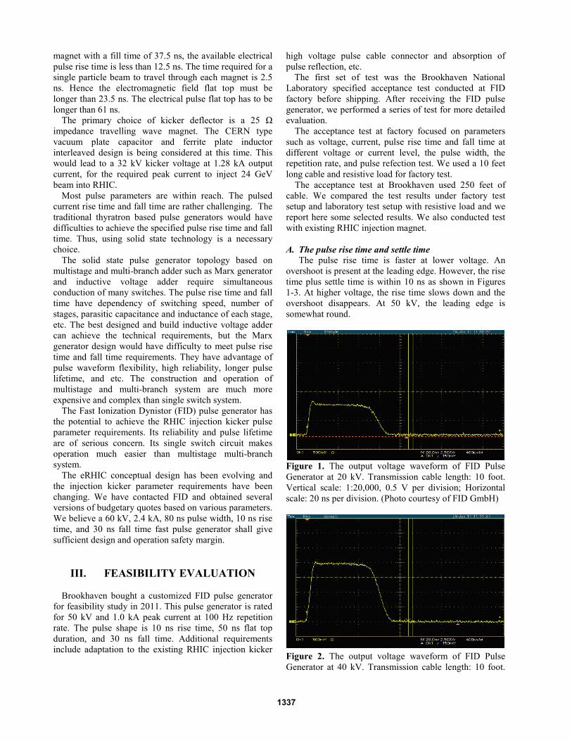
high voltage pulse cable connector and absorption of pulse reflection, etc. The first set of test was the Brookhaven National Laboratory specified acceptance test conducted at FID factory before shipping. After receiving the FID pulse generator, we performed a series of test for more detailed evaluation. The acceptance test at factory focused on parameters such as voltage, current, pulse rise time and fall time at different voltage or current level, the pulse width, the repetition rate, and pulse refection test. We used a 10 feet long cable and resistive load for factory test. The acceptance test at Brookhaven used 250 feet of cable. We compared the test results under factory test setup and laboratory test setup with resistive load and we report here some selected results. We also conducted test with existing RHIC injection magnet. A. The pulse rise time and settle time The pulse rise time is faster at lower voltage. An overshoot is present at the leading edge. However, the rise time plus settle time is within 10 ns as shown in Figures 1-3. At higher voltage, the rise time slows down and the overshoot disappears. At 50 kV, the leading edge is somewhat round.
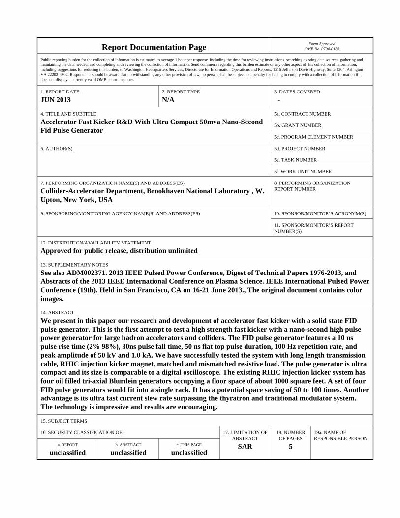
Figure 1. The output voltage waveform of FID Pulse Generator at 20 kV. Transmission cable length: 10 foot. Vertical scale: 1:20,000, 0.5 V per division; Horizontal scale: 20 ns per division. (Photo courtesy of FID GmbH)
Figure 2. The output voltage waveform of FID Pulse Generator at 40 kV. Transmission cable length: 10 foot.
1337
Vertical scale: 1:20,000, 0.5 V per division; Horizontal scale: 20 ns per division. (Photo courtesy of FID GmbH)
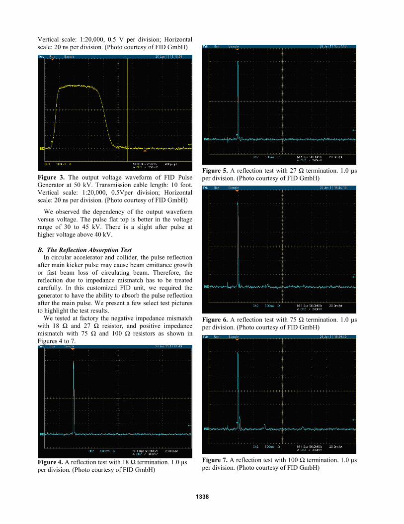
Figure 3. The output voltage waveform of FID Pulse Generator at 50 kV. Transmission cable length: 10 foot. Vertical scale: 1:20,000, 0.5Vper division; Horizontal scale: 20 ns per division. (Photo courtesy of FID GmbH)
We observed the dependency of the output waveform versus voltage. The pulse flat top is better in the voltage range of 30 to 45 kV. There is a slight after pulse at higher voltage above 40 kV. B. The Reflection Absorption Test In circular accelerator and collider, the pulse reflection after main kicker pulse may cause beam emittance growth or fast beam loss of circulating beam. Therefore, the reflection due to impedance mismatch has to be treated carefully. In this customized FID unit, we required the generator to have the ability to absorb the pulse reflection after the main pulse. We present a few select test pictures to highlight the test results. We tested at factory the negative impedance mismatch with 18 Ω and 27 Ω resistor, and positive impedance mismatch with 75 Ω and 100 Ω resistors as shown in Figures 4 to 7.
Figure 4. A reflection test with 18 Ω termination. 1.0 μs per division. (Photo courtesy of FID GmbH)
Figure 5. A reflection test with 27 Ω termination. 1.0 μs per division. (Photo courtesy of FID GmbH)
Figure 6. A reflection test with 75 Ω termination. 1.0 μs per division. (Photo courtesy of FID GmbH)
Figure 7. A reflection test with 100 Ω termination. 1.0 μs per division. (Photo courtesy of FID GmbH)
1338
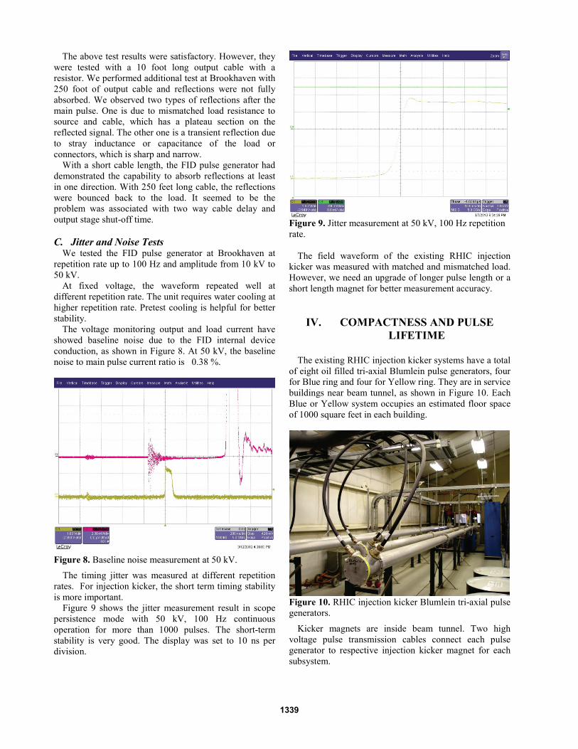
The above test results were satisfactory. However, they were tested with a 10 foot long output cable with a resistor. We performed additional test at Brookhaven with 250 foot of output cable and reflections were not fully absorbed. We observed two types of reflections after the main pulse. One is due to mismatched load resistance to source and cable, which has a plateau section on the reflected signal. The other one is a transient reflection due to stray inductance or capacitance of the load or connectors, which is sharp and narrow. With a short cable length, the FID pulse generator had demonstrated the capability to absorb reflections at least in one direction. With 250 feet long cable, the reflections were bounced back to the load. It seemed to be the problem was associated with two way cable delay and output stage shut-off time. C. Jitter and Noise Tests We tested the FID pulse generator at Brookhaven at repetition rate up to 100 Hz and amplitude from 10 kV to 50 kV. At fixed voltage, the waveform repeated well at different repetition rate. The unit requires water cooling at higher repetition rate. Pretest cooling is helpful for better stability. The voltage monitoring output and load current have showed baseline noise due to the FID internal device conduction, as shown in Figure 8. At 50 kV, the baseline noise to main pulse current ratio is 0.38 %.
Figure 8. Baseline noise measurement at 50 kV.
The timing jitter was measured at different repetition rates. For injection kicker, the short term timing stability is more important. Figure 9 shows the jitter measurement result in scope persistence mode with 50 kV, 100 Hz continuous operation for more than 1000 pulses. The short-term stability is very good. The display was set to 10 ns per division.
Figure 9. Jitter measurement at 50 kV, 100 Hz repetition rate. The field waveform of the existing RHIC injection kicker was measured with matched and mismatched load. However, we need an upgrade of longer pulse length or a short length magnet for better measurement accuracy.
IV. COMPACTNESS AND PULSE LIFETIME
The existing RHIC injection kicker systems have a total of eight oil filled tri-axial Blumlein pulse generators, four for Blue ring and four for Yellow ring. They are in service buildings near beam tunnel, as shown in Figure 10. Each Blue or Yellow system occupies an estimated floor space of 1000 square feet in each building.
Figure 10. RHIC injection kicker Blumlein tri-axial pulse generators.
Kicker magnets are inside beam tunnel. Two high voltage pulse transmission cables connect each pulse generator to respective injection kicker magnet for each subsystem.
1339
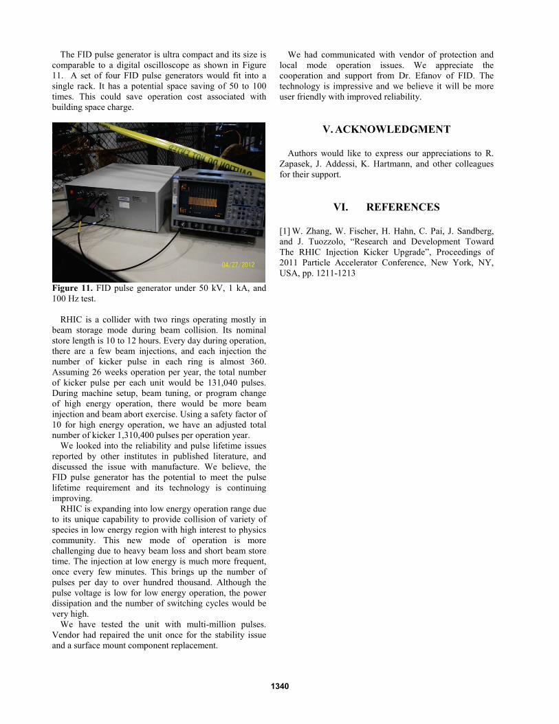
The FID pulse generator is ultra compact and its size is comparable to a digital oscilloscope as shown in Figure 11. A set of four FID pulse generators would fit into a single rack. It has a potential space saving of 50 to 100 times. This could save operation cost associated with building space charge.
Figure 11. FID pulse generator under 50 kV, 1 kA, and 100 Hz test. RHIC is a collider with two rings operating mostly in beam storage mode during beam collision. Its nominal store length is 10 to 12 hours. Every day during operation, there are a few beam injections, and each injection the number of kicker pulse in each ring is almost 360. Assuming 26 weeks operation per year, the total number of kicker pulse per each unit would be 131,040 pulses. During machine setup, beam tuning, or program change of high energy operation, there would be more beam injection and beam abort exercise. Using a safety factor of 10 for high energy operation, we have an adjusted total number of kicker 1,310,400 pulses per operation year. We looked into the reliability and pulse lifetime issues reported by other institutes in published literature, and discussed the issue with manufacture. We believe, the FID pulse generator has the potential to meet the pulse lifetime requirement and its technology is continuing improving. RHIC is expanding into low energy operation range due to its unique capability to provide collision of variety of species in low energy region with high interest to physics community. This new mode of operation is more challenging due to heavy beam loss and short beam store time. The injection at low energy is much more frequent, once every few minutes. This brings up the number of pulses per day to over hundred thousand. Although the pulse voltage is low for low energy operation, the power dissipation and the number of switching cycles would be very high. We have tested the unit with multi-million pulses. Vendor had repaired the unit once for the stability issue and a surface mount component replacement.
We had communicated with vendor of protection and local mode operation issues. We appreciate the cooperation and support from Dr. Efanov of FID. The technology is impressive and we believe it will be more user friendly with improved reliability.
V. ACKNOWLEDGMENT Authors would like to express our appreciations to R. Zapasek, J. Addessi, K. Hartmann, and other colleagues for their support.
VI. REFERENCES [1] W. Zhang, W. Fischer, H. Hahn, C. Pai, J. Sandberg, and J. Tuozzolo, “Research and Development Toward The RHIC Injection Kicker Upgrade”, Proceedings of 2011 Particle Accelerator Conference, New York, NY, USA, pp. 1211-1213
1340