A MATLAB-SIMULINK APPROACH TO SHUNT ACTIVE …scs-europe.net/conf/ecms2011/ecms2011 accepted... ·...
6
A MATLAB-SIMULINK APPROACH TO SHUNT ACTIVE POWER FILTERS George Adam, Alina G. Stan (Baciu) and Gheorghe Livinţ Department of Electrical Engineering Technical University of Iaşi 700050, Iaşi, Romania E-mail: [email protected] KEYWORDS Active Power Filters, Computer Simulation, Current Harmonics, Reactive Power, Unbalance ABSTRACT Due to the wide spread of power electronics equipment in modern electrical systems, the increase of the harmonics disturbance in the ac mains currents has became a major concern due to the adverse effects on all equipment. This paper presents the analysis and simulation using Matlab Simulink of a three-phase four wire neutral clamped active power filter (APF) compensating the harmonics and reactive power created by nonlinear balanced and unbalanced low power loads in steady state and in transients. The usefulness of the simulation approach to APF is demonstrated so APF designers have a better insight using Matlab Simulink in order to develop new APFs. INTRODUCTION Modern electrical systems, due to wide spread of power conversion units and power electronics equipments, causes an increasing harmonics disturbance in the ac mains currents. These harmonics currents causes adverse effects in power systems such as overheating, perturbation of sensitive control and communication equipment, capacitor blowing, motor vibration, excessive neutral currents, resonances with the grid and low power factor (Maswood and Haque 2002). As a result, effective harmonic reduction from the system has become important both to the utilities and to the users. The total harmonic distortion is the ratio between the RMS value of the sum of all harmonic components and the RMS value of the fundamental component, for both current and voltage, as in equation (1): [%] = 100 ∙ ℎ 1 2 ∞ ℎ =2 (1) where h is the order of the harmonic. Traditionally, the simplest method to eliminate current harmonics is the usage of passive LC filters, but they have many drawbacks such as large size, tuning problems, resonance and fixed compensation characteristics. The solution over passive filters for compensating the harmonic distortion and unbalance is the shunt active power filter (APF). In order to compensate the distorted currents the APF injects currents equal but opposite with the harmonic components, thus only the fundamental components flows in the point of common coupling (PCC) as in equation (2): = ℎ ∞ ℎ =2 (2) where h is the order of the harmonic i l is the load current. The APF, connected in parallel to the disturbing loads, unbalanced and non-linear, as seen in figure 1, causes the supply currents to be near sinusoidal and balanced. Figure 1 : Active filter principle For the design of active power filters, simulation has been proved a very useful tool, using different programs, like Matlab (Zamora et al. 2003; Singh et al., 1999), RT-LAB (Balan et al.) or PSCAD (Iyer et al, 2005). The usage of computer in the design phase has a great impact in understanding the APF behavior, selection of components, tuning controllers and optimizing. Proceedings 25th European Conference on Modelling and Simulation ©ECMS Tadeusz Burczynski, Joanna Kolodziej Aleksander Byrski, Marco Carvalho (Editors) ISBN: 978-0-9564944-2-9 / ISBN: 978-0-9564944-3-6 (CD)
Transcript of A MATLAB-SIMULINK APPROACH TO SHUNT ACTIVE …scs-europe.net/conf/ecms2011/ecms2011 accepted... ·...
A MATLAB-SIMULINK APPROACH TO SHUNT ACTIVE POWER
FILTERS
George Adam, Alina G. Stan (Baciu) and Gheorghe Livinţ
Department of Electrical Engineering
Technical University of Iaşi
700050, Iaşi, Romania
E-mail: [email protected]
KEYWORDS
Active Power Filters, Computer Simulation, Current
Harmonics, Reactive Power, Unbalance
ABSTRACT
Due to the wide spread of power electronics equipment
in modern electrical systems, the increase of the
harmonics disturbance in the ac mains currents has
became a major concern due to the adverse effects on
all equipment. This paper presents the analysis and
simulation using Matlab Simulink of a three-phase four
wire neutral clamped active power filter (APF)
compensating the harmonics and reactive power
created by nonlinear balanced and unbalanced low
power loads in steady state and in transients. The
usefulness of the simulation approach to APF is
demonstrated so APF designers have a better insight
using Matlab Simulink in order to develop new APFs.
INTRODUCTION
Modern electrical systems, due to wide spread of
power conversion units and power electronics
equipments, causes an increasing harmonics
disturbance in the ac mains currents. These harmonics
currents causes adverse effects in power systems such
as overheating, perturbation of sensitive control and
communication equipment, capacitor blowing, motor
vibration, excessive neutral currents, resonances with
the grid and low power factor (Maswood and Haque
2002). As a result, effective harmonic reduction from
the system has become important both to the utilities
and to the users.
The total harmonic distortion is the ratio between the
RMS value of the sum of all harmonic components and
the RMS value of the fundamental component, for both
current and voltage, as in equation (1):
𝑇𝐻𝐷[%] = 100 ∙ 𝐼ℎ𝐼1
2∞
ℎ=2
(1)
where h is the order of the harmonic.
Traditionally, the simplest method to eliminate current
harmonics is the usage of passive LC filters, but they
have many drawbacks such as large size, tuning
problems, resonance and fixed compensation
characteristics. The solution over passive filters for
compensating the harmonic distortion and unbalance is
the shunt active power filter (APF). In order to
compensate the distorted currents the APF injects
currents equal but opposite with the harmonic
components, thus only the fundamental components
flows in the point of common coupling (PCC) as in
equation (2):
𝑖𝑓 = 𝑖𝑙ℎ
∞
ℎ=2
(2)
where h is the order of the harmonic
il is the load current.
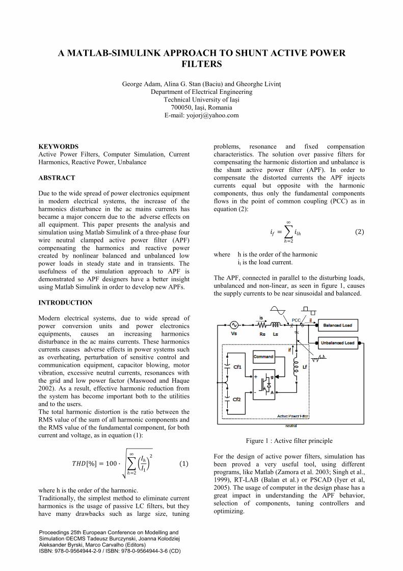
The APF, connected in parallel to the disturbing loads,
unbalanced and non-linear, as seen in figure 1, causes
the supply currents to be near sinusoidal and balanced.
Figure 1 : Active filter principle
For the design of active power filters, simulation has
been proved a very useful tool, using different
programs, like Matlab (Zamora et al. 2003; Singh et al.,
1999), RT-LAB (Balan et al.) or PSCAD (Iyer et al,
2005). The usage of computer in the design phase has a
great impact in understanding the APF behavior,
selection of components, tuning controllers and
optimizing.
Proceedings 25th European Conference on Modelling andSimulation ©ECMS Tadeusz Burczynski, Joanna KolodziejAleksander Byrski, Marco Carvalho (Editors)ISBN: 978-0-9564944-2-9 / ISBN: 978-0-9564944-3-6 (CD)
The studied APF in this paper by using the Matlab
Simulink environment is a three-phase four wire
neutral clamped APF compensating harmonics,
unbalance and reactive power created first by a
nonlinear balanced load and then by a nonlinear
unbalanced load based on the Instantaneous Reactive
Power Theory (IRPT).
REACTIVE POWER CONTROL
This theory was proposed by (Akagi et al. 1983) for
three-phase systems with or without neutral wire, and it
is valid for both steady state and transients. It consists
in the algebraic transformation of the current and
voltage of the system from the abc system to αβ0
system using the Clarke transformation as in equation
(3) and (4).
𝑖𝛼𝑖𝛽𝑖0
= 2
3
1 − 1
2 − 12
0 32
− 32
22
22
22
𝑖𝐿𝑎𝑖𝐿𝑏𝑖𝐿𝑐
(3)
𝑣𝛼
𝑣𝛽
𝑣0
= 2
3
1 − 1
2 − 12
0 32
− 32
22
22
22
𝑣𝐿𝑎
𝑣𝐿𝑏
𝑣𝐿𝑐
(4)
where iLa, iLb, iLc are the load currents and vLa, vLb and
vLc are the load voltages.
According to the p-q theory, the active, reactive and
zero-sequence powers are defined as in equations (5a
and 5b) and (6):
𝑝 = 𝑣𝛼 𝑖𝛼 + 𝑣𝛽 𝑖𝛽 (5𝑎)
𝑞 = 𝑣𝛼 𝑖𝛽 − 𝑣𝛽 𝑖𝛼 (5𝑏)
𝑝0 = 𝑣0𝑖0 (6)
The currents, voltages and powers in the α-β system
can be decomposed in mean and alternating values,
corresponding to the fundamental and harmonic
components, as in equation (7).
𝑥 = 𝑥 + 𝑥 (7)
where x can be currents, voltages or powers.
The power components have the following physical
meaning (Afonso J.L. et al., 2003):
p0 zero sequence power. It only exists in three-phase
systems with neutral wire. Since it is an undesired
power component because it only exchanges energy
with the load, it must be compensated. From
equation (6) it can be seen that p0=v0i0, but
i0*=p0/v0=i0, so there is no need for computing p0.
𝑝 mean value of the instantaneous real power. It is the
only desired power component to be supplied by
the source because it corresponds to the energy
transferred from the source to the load.
𝑝 alternating value of instantaneous real power. Since
it does not involve any energy transfer from the
source to the load, it must be compensated.
𝑞 mean value of imaginary power. It corresponds to
the power exchanged between the phases of the
load and is responsable for the existence of
undesired current. It must be compensated.
𝑞 alternating value of imaginary power. It
corresponds to the conventional reactive power. It
can be compensated by the APF, depending on the
requirements of the system.
Since in the p-q theory the voltages are assumed
sinusoidal, the power components must be computed
using sinusoidal voltages. In the α-β voltage system,
the AC components of the voltage are eliminated in
order to the IRPT to provide good performance.
Conventionally, in IRPT control, are used High Pass
(HP) and Low Pass (LP) Filters, but this method has a
high error in the phase and magnitude of the harmonics
and also is sensitive to high-frequency noise. Even
worse, there is a need of five HP or LP filters – for α-β
voltage components, and for p,q and p0 power
components.
This paper presents a control scheme based on the
usage of only two self-tuning filters.
The powers required to be compensated by the APF are
calculated as in equation (8):
𝑝 𝑞 =
𝑣𝛼 𝑣𝛽
0 0
𝑖𝛼 𝑖𝛽
+ 0 0
−𝑣𝛽 𝑣𝛼
𝑖𝛼𝑖𝛽
(8)
After adding the active power required to regulate the
DC bus voltage, ploss to the alternative value of
instantaneous real power, the reference currents iαβ* are
calculated by equation (9):
𝑖𝛼∗
𝑖𝛽∗ =
1
Δ𝑇
0𝑞 +
1
Δ𝑇
𝑝 + 𝑝𝑙𝑜𝑠𝑠
𝑞 (9)
where:
Δ = 𝑣𝛼 2 + 𝑣𝛽
2
𝑇 = 𝑣𝛼 −𝑣𝛽
𝑣𝛽 𝑣𝛼
From equation (8) it can be seen that the APF
computes 𝑝 using the harmonic components of the
currents while 𝑞 = 𝑞 + 𝑞 are computed using the load
current, including AC and DC components, according
to figure 2.
The load currents are transformed from three-phase abc
to αβ0 components using Clarke transformation, as in
equation (10):
𝑖𝑎∗
𝑖𝑏∗
𝑖𝑐∗ =
2
3
1 0 2
2
− 12
32
22
− 12 − 3
2 2
2
𝑖𝛼∗
𝑖𝛽∗
𝑖0∗
(10)
Proceedings 25th European Conference on Modelling andSimulation ©ECMS Tadeusz Burczynski, Joanna KolodziejAleksander Byrski, Marco Carvalho (Editors)ISBN: 978-0-9564944-2-9 / ISBN: 978-0-9564944-3-6 (CD)
The compensation strategy based on the p-q theory of
all undesired power components (p , p0 and q) can be
accomplished with the use of the shunt active power
filter.
Figure 2: Proposed power control strategy
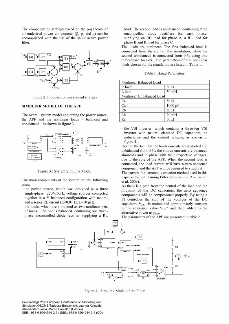
SIMULINK MODEL OF THE APF
The overall system model containing the power source,
the APF and the nonlinear loads – balanced and
unbalanced – is shown in figure 3.
Figure 3 : System Simulink Model
The main components of the system are the following
ones:
- the power source, which was designed as a three
single-phase 220V/50Hz voltage sources connected
together in a Y balanced configuration with neutral
and a series RL circuit (R=0.01 Ω, L=10 μH).
- the loads, which are simulated as two nonlinear sets
of loads. First one is balanced, containing one three-
phase uncontrolled diode rectifier supplying a RL
load. The second load is unbalanced, containing three
uncontrolled diode rectifiers for each phase,
supplying an RC load for phase A, a RL load for
phase B and R load for phase C.
The loads are nonlinear. The first balanced load is
connected from the start of the simulation, while the
second unbalanced is connected from 0.6s using one
three-phase breaker. The parameters of the nonlinear
loads chosen for the simulation are listed in Table 1.
Table 1 : Load Parameters
Nonlinear Balanced Load
R load 30 Ω
L load 30 mH
Nonlinear Unbalanced Load
Ra 50 Ω
Ca 1000 μF
Rb 50 Ω
Lb 20 mH
Rc 50 Ω
- the VSI inverter, which contains a three-leg VSI
inverter with neutral clamped DC capacitors, an
inductance and the control scheme, as shown in
figure 4.
Despite the fact that the loads currents are distorted and
unbalanced from 0.6s, the source currents are balanced
sinusoids and in phase with their respective voltages,
due to the role of the APF. When the second load is
connected, the load current will have a zero sequence
component and the APF will be required to supply it.
The current fundamental extraction method used in this
paper is the Self Tuning Filter proposed in (Abdusalam
et al. 2009).
As there is a path from the neutral of the load and the
midpoint of the DC capacitors, the zero sequence
components will be compensated properly. By using a
PI controller the sum of the voltages of the DC
capacitors VDC is maintained approximately constant
to the reference value VDC* and then added to the
alternative power as ploss.
The parameters of the APF are presented in table 2.
Figure 4 : Simulink Model of the Filter
vabc vαβ
iabc iαβ
+
-
+
+
+
-
vαβ
iαβ
vDC*
vDC
i0* ploss
q + q
p iαβ* iabc*
PI
(4)
(3)
(8)
(8) (9) (10)
~/=
~/=
Proceedings 25th European Conference on Modelling andSimulation ©ECMS Tadeusz Burczynski, Joanna KolodziejAleksander Byrski, Marco Carvalho (Editors)ISBN: 978-0-9564944-2-9 / ISBN: 978-0-9564944-3-6 (CD)
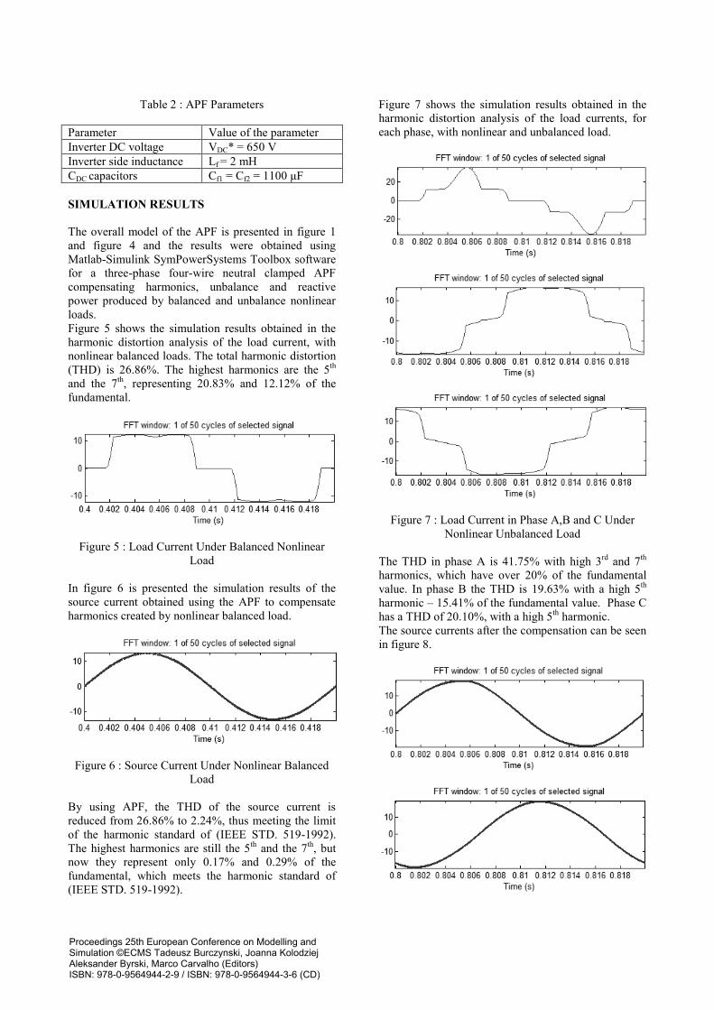
Table 2 : APF Parameters
Parameter Value of the parameter
Inverter DC voltage VDC* = 650 V
Inverter side inductance Lf = 2 mH
CDC capacitors Cf1 = Cf2 = 1100 μF
SIMULATION RESULTS
The overall model of the APF is presented in figure 1
and figure 4 and the results were obtained using
Matlab-Simulink SymPowerSystems Toolbox software
for a three-phase four-wire neutral clamped APF
compensating harmonics, unbalance and reactive
power produced by balanced and unbalance nonlinear
loads.
Figure 5 shows the simulation results obtained in the
harmonic distortion analysis of the load current, with
nonlinear balanced loads. The total harmonic distortion
(THD) is 26.86%. The highest harmonics are the 5th
and the 7th
, representing 20.83% and 12.12% of the
fundamental.
Figure 5 : Load Current Under Balanced Nonlinear
Load
In figure 6 is presented the simulation results of the
source current obtained using the APF to compensate
harmonics created by nonlinear balanced load.
Figure 6 : Source Current Under Nonlinear Balanced
Load
By using APF, the THD of the source current is
reduced from 26.86% to 2.24%, thus meeting the limit
of the harmonic standard of (IEEE STD. 519-1992).
The highest harmonics are still the 5th
and the 7th
, but
now they represent only 0.17% and 0.29% of the
fundamental, which meets the harmonic standard of
(IEEE STD. 519-1992).
Figure 7 shows the simulation results obtained in the
harmonic distortion analysis of the load currents, for
each phase, with nonlinear and unbalanced load.
Figure 7 : Load Current in Phase A,B and C Under
Nonlinear Unbalanced Load
The THD in phase A is 41.75% with high 3rd
and 7th
harmonics, which have over 20% of the fundamental
value. In phase B the THD is 19.63% with a high 5th
harmonic – 15.41% of the fundamental value. Phase C
has a THD of 20.10%, with a high 5th
harmonic.
The source currents after the compensation can be seen
in figure 8.
Proceedings 25th European Conference on Modelling andSimulation ©ECMS Tadeusz Burczynski, Joanna KolodziejAleksander Byrski, Marco Carvalho (Editors)ISBN: 978-0-9564944-2-9 / ISBN: 978-0-9564944-3-6 (CD)
Figure 8 : Source Current in Phase A,B and C Under
Nonlinear Unbalanced Load
In phase A the THD is now 2.66%, and the magnitude
of the 3rd
harmonic is now only 1.79% of the
fundamental. In phase B the THD is 2.11% and in
phase C the THD is 2.28%, thus meeting the harmonic
standard of (IEEE STD. 519-1992).
In order to be effective, APF must also eliminate the
neutral current from three-phase unbalanced loads.
Figure 9 shows that even when connecting at 0.6s the
unbalanced load the neutral current is close to 0A.
Figure 9 : Neutral Current Elimination
The following figure shows the simulation results of
the APF under transient state. Since the start of the
simulation the balanced load is connected. Since 0.3s,
the APF is connected and since 0.6s the unbalanced
load. Figure 10 shows the source current in phase A
under transients.
Figure 10 : Overall Source Current in Phase A
It can be seen that when connecting the filter it takes
only 0.025s for the APF to compensate. When the
second load is connected, it takes only 0.025s for the
APF to follow the change of the load current.
The THD levels and harmonic magnitudes of the
source currents with and without APF are shown in
table 3 and table 4.
Table 3 : THD Levels of Source Currents
THD level
without APF [%]
THD level with
APF [%]
Balanced load
26.86 2.24
Unbalanced load
phase A 41.75 2.66
phase B 19.63 2.11
phase C 20.10 2.28
It can be seen from table 4 and figure 11 that under
only unbalanced load without the APF, the
fundamental has 3 different values. Using the APF the
new fundamental on each phase has close to the same
value of 19A, which prove that the APF also make the
source currents symmetrical.
Table 4 : 1,3 and 5 Harmonic Magnitudes
1st
[A] 3
rd [A] 5
th [A]
- + - + - +
Balanced load
13.23 13.27 0 0.18 20.83 0.17
Unbalanced load
A 21.56 18.98 32.75 1.81 10.92 0.7
B 17.53 18.88 0.45 0.87 15.41 0.54
C 17.66 19.26 0.46 1.27 15.88 0.63
where : “-“ means without APF
“+” means with APF
Figure 11 : Source Current Without and With APF
Under Unbalanced Load
Figure 12 shows that when connecting the APF at 0.3s
the reactive power decreases close to zero, even when
the unbalanced load is connected at 0.6s, proven that
the APF is a very effective tool to compensate reactive
power.
C A B
Proceedings 25th European Conference on Modelling andSimulation ©ECMS Tadeusz Burczynski, Joanna KolodziejAleksander Byrski, Marco Carvalho (Editors)ISBN: 978-0-9564944-2-9 / ISBN: 978-0-9564944-3-6 (CD)
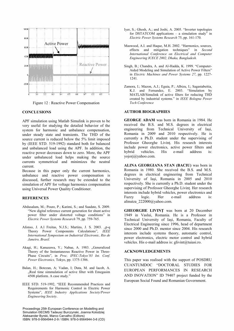
Figure 12 : Reactive Power Compensation
CONCLUSIONS
APF simulation using Matlab Simulink is proven to be
very useful for studying the detailed behavior of the
system for harmonic and unbalance compensation,
under steady state and transients. The THD of the
source current is reduced below the 5% limit imposed
by (IEEE STD. 519-1992) standard both for balanced
and unbalanced load using the APF. In addition, the
reactive power decreases down to zero. More, the APF
under unbalanced load helps making the source
currents symmetrical and minimizes the neutral
current.
Because in this paper only the current harmonics,
unbalance and reactive power compensation is
discussed, further research may be extended to the
simulation of APF for voltage harmonics compensation
using Universal Power Quality Conditioner.
REFERENCES
Abdusalam, M.; Poure, P.; Karimi, S.; and Saadate, S. 2009.
“New digital reference current generation for shunt active
power filter under distorted voltage conditions” in
Electric Power Systems Research 79, pp. 759-765.
Afonso, J. A.l Freitas, N.J.S.; Martins, J. S. 2003. „p-q
Theory Power Components Calculations”, IEEE
International Symposium on Industrial Electronic, Rio de
Janeiro, Brasil.
Akagi, H.; Kanazawa, Y.; Nabae, A. 1983. „Generalized
Theory of the Instantaneous Reactive Power in Three-
Phase Circuits”, in Proc. IPEC-Tokyo’83 Int. Conf.
Power Electronics, Tokyo, pp. 1375-1386.
Balan, H.; Botezan, A; Vadan, I; Duta, M. and Iacob, A.
„Real time simmulation of active filter with Emegasim
4508 platform. A case study.”
IEEE STD. 519-1992, “IEEE Recommended Practices and
Requirements for Harmonic Control in Electric Power
Systems”, IEEE Industry Applications Society/Power
Engineering Society.
Iyer, S.; Ghosh, A.; and Joshi, A. 2005. “Inverter topologies
for DSTATCOM applications – a simulation study” in
Electric Power Systems Research 75, pp. 161-170.
Maswood, A.I. and Haque, M.H. 2002. “Harmonics, sources,
effects and mitigation techniques” in Second
International Conference on Electrical and Computer
Engineering ICECE 2002, Dhaka, Bangladesh.
Singh, B.; Chandra, A. and Al-Hadda, K. 1999. “Computer-
Aided Modeling and Simulation of Active Power Filters”
in Electric Machines and Power Systems 27, pp. 1227-
1241.
Zamora, I.; Mazon, A.J.; Eguia, P.; Albizu, I.; Sagastabeitia,
K.J. and Fernandez, E. 2003. “Simulation by
MATLAB/Simulink of active filters for reducing THD
created by industrial systems.” in IEEE Bologna Power
Tech Conference
AUTHOR BIOGRAPHIES
GEORGE ADAM was born in Romania in 1984. He
received the B.S. and M.S. degrees in electrical
engineering from Technical University of Iaşi,
Romania in 2009 and 2010 respectively. He is
currently a Ph.D. student under the supervising of
Professor Gheorghe Livinţ. His research interests
include power electronics, active power filters and
hybrid vehicles. His e-mail address is:
ALINA GEORGIANA STAN (BACIU) was born in
Romania in 1980. She received the B.S. and M.S.
degrees in electrical engineering from Technical
University of Iaşi, Romania in 2005 and 2010
respectively. She is currently a Ph.D. student under the
supervising of Professor Gheorghe Livinţ. Her research
interests include hybrid vehicles, power electronics and
Fuzzy logic. Her e-mail address is:
GHEORGHE LIVINŢ was born at 20 December
1949 in Vaslui, Romania. He is a Professor in
Technical University of Iaşi, Romania, Faculty of
Electrical Engineering since 1996, head of department
since 2000 and Ph.D. mentor since 2004. His research
interests include systems theory, automatic control,
power electronics, electric motor control and hybrid
vehicles. His e-mail address is: [email protected].
ACKNOWLEDGEMENTS
This paper was realised with the support of POSDRU
CUANTUMDOC “DOCTORAL STUDIES FOR
EUROPEAN PERFORMANCES IN RESEARCH
AND INOVATION” ID 79407 project funded by the
European Social Found and Romanian Government.
Active Power
Reactive Power
Proceedings 25th European Conference on Modelling andSimulation ©ECMS Tadeusz Burczynski, Joanna KolodziejAleksander Byrski, Marco Carvalho (Editors)ISBN: 978-0-9564944-2-9 / ISBN: 978-0-9564944-3-6 (CD)