A σ lim A 0 . Dimensions of force per unit area...2 Can do stress rotation problems in your head....
12
GG711c 1/15/10 1 Stephen Martel 4-1 University of Hawaii STRESS AT A POINT I Main Topics A Stress vector (traction) on a plane B Stress at a point C Principal stresses D Stress transformation equations II Stress vector (traction) on a particular plane : σ → A σ → = lim A→0 F → / A . Dimensions of force per unit area B Traction vectors can be added vectorially. C A traction vector can be resolved into normal and shear components. C A traction vector can be resolved into normal and shear components. 1 A normal traction τ → n acts perpendicular to a plane 2 A shear traction τ → s acts parallel to a plane D The magnitudes of tractions depend on the orientation of the plane III Stress at a point A Stresses refer to balanced internal "forces (per unit area)". They differ from force vectors, which, if unbalanced, cause accelerations B "On -in convention": The stress component σ ij acts on the plane normal to the i-direction and acts in the j-direction 1 Normal stresses: i=j 2 Shear stresses: i≠j
Transcript of A σ lim A 0 . Dimensions of force per unit area...2 Can do stress rotation problems in your head....
GG711c 1/15/10 1
Stephen Martel 4-1 University of Hawaii
STRESS AT A POINT I Main Topics
A Stress vector (traction) on a plane B Stress at a point C Principal stresses D Stress transformation equations
II Stress vector (traction) on a particular plane: σ→
A σ→
= limA→0 F→/ A . Dimensions of force per unit area
B Traction vectors can be added vectorially. C A traction vector can be resolved into normal and shear components. C A traction vector can be resolved into normal and shear components.
1 A normal traction
€
τ→
n acts perpendicular to a plane
2 A shear traction
€
τ→
s acts parallel to a plane D The magnitudes of tractions depend on the orientation of the plane
III Stress at a point
A Stresses refer to balanced internal "forces (per unit area)". They differ
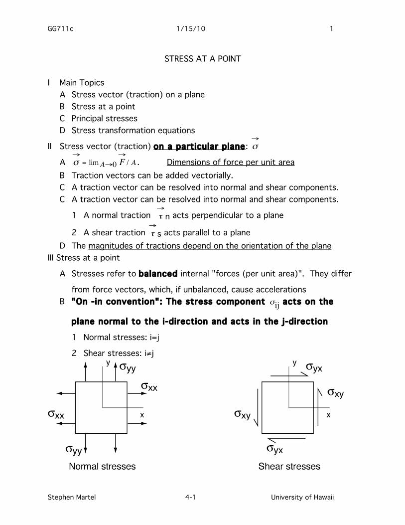
from force vectors, which, if unbalanced, cause accelerations B "On -in convention": The stress component
€
σij acts on the
plane normal to the i-direction and acts in the j-direction
1 Normal stresses: i=j
2 Shear stresses: i≠j
GG711c 1/15/10 2
Stephen Martel 4-2 University of Hawaii
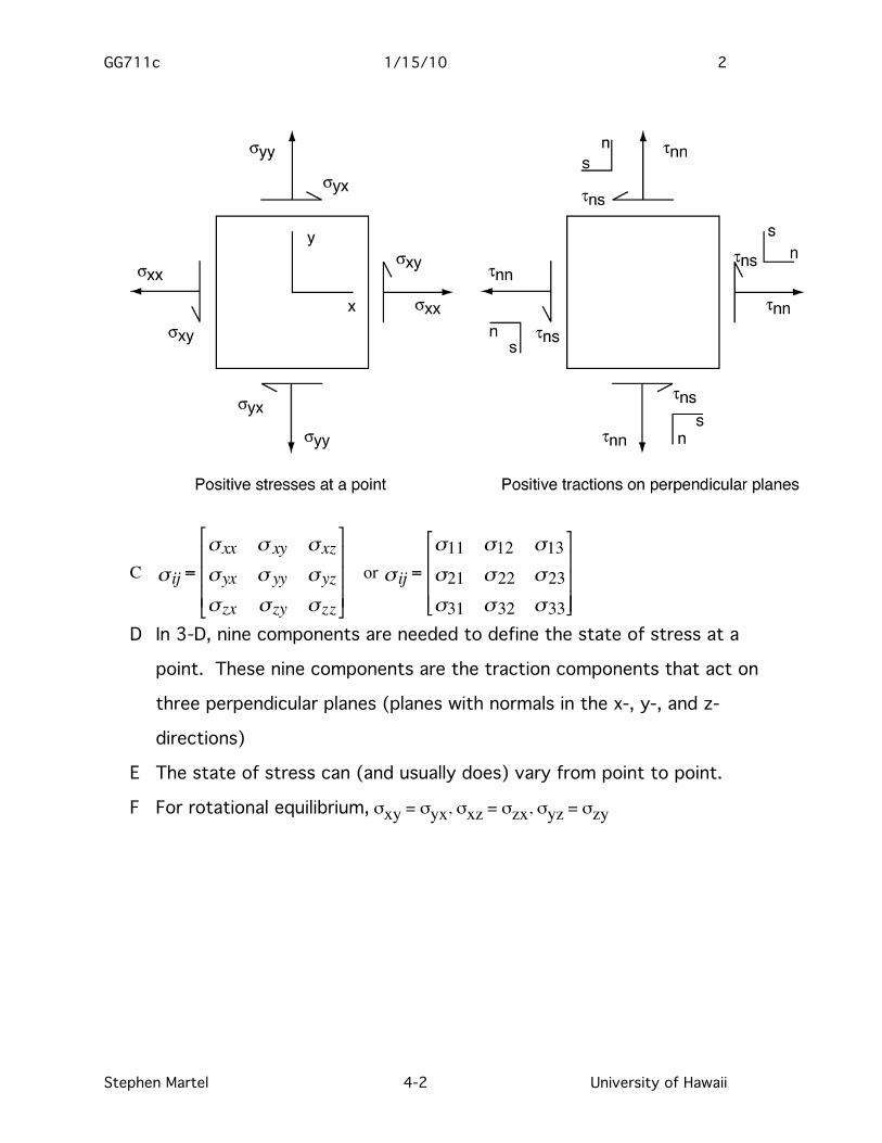
C ijσ =xxσ xyσ xzσ
yxσ yyσ yzσ
zxσ zyσ zzσ
or ijσ =11σ 12σ 13σ
21σ 22σ 23σ
31σ 32σ 33σ
D In 3-D, nine components are needed to define the state of stress at a
point. These nine components are the traction components that act on
three perpendicular planes (planes with normals in the x-, y-, and z-
directions)
E The state of stress can (and usually does) vary from point to point.
F For rotational equilibrium, σxy = σyx, σxz = σzx, σyz = σzy
GG711c 1/15/10 3
Stephen Martel 4-3 University of Hawaii
IV Principal Stresses (these have magnitudes and orientations)
A Principal stresses act on planes which feel no shear stress
B The principal stresses are normal stresses.
C Principal stresses act on perpendicular planes
D The maximum, intermediate, and minimum principal stresses are usually designated σ1, σ2, and σ3, respectively. Note that the principal stresses
have a single subscript.
E The principal stresses represent the stress state most simply.
F σij =
σ1 0 00 σ2 00 0 σ3
3-D or σij =σ1 00 σ2
2-D
V Tensor transformation of stresses between planes of arbitrary orientation
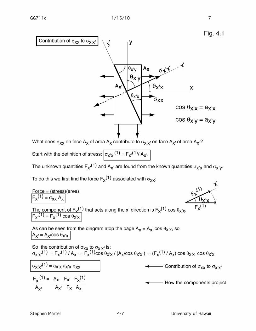
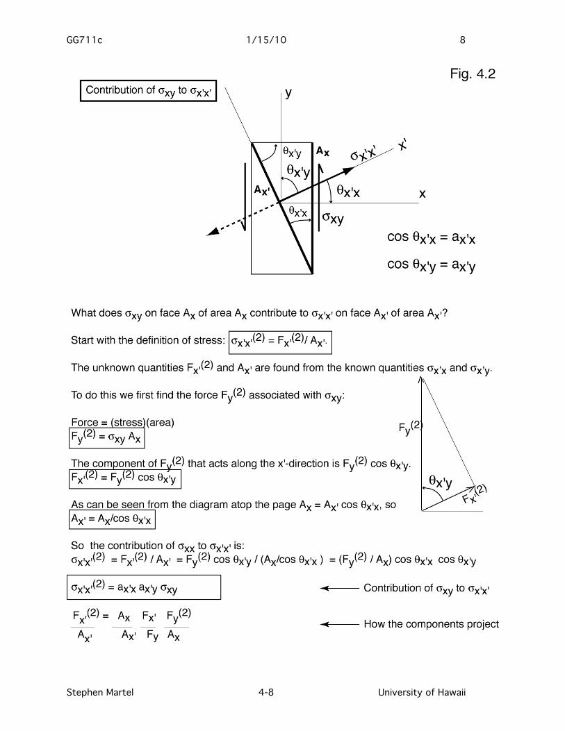
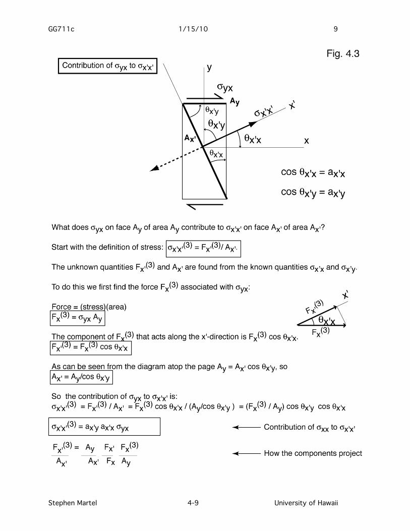
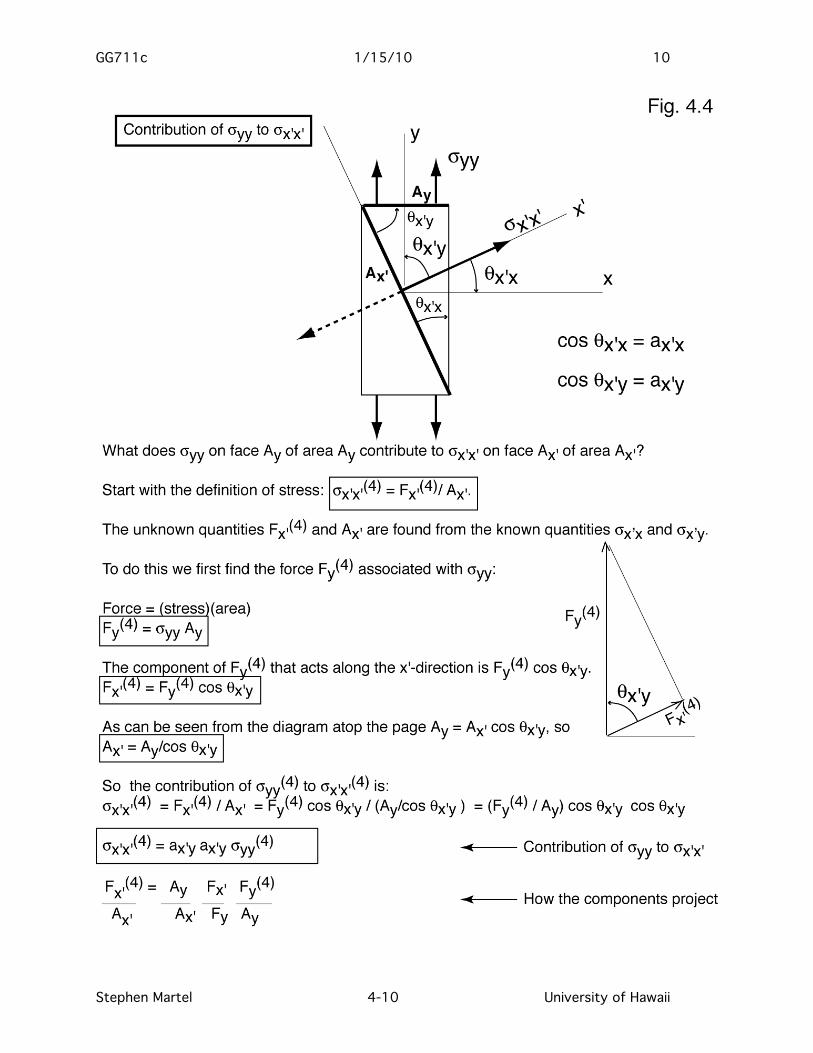
In the 2-D example of lecture 16, the normal and shear stresses (tractions) were found on one arbitrarily oriented plane in the n,s reference frame. Here we consider two perpendicular (but otherwise arbitrarily oriented) planes, one perpendicular to the x’-axis, and the other perpendicular to the y’-axis and seek to find the normal and shear stress acting on them. In lecture 16 we considered the case where no shear stresses acted on the planes perpendicular to the x- and y-axes. We address here the more general case where shear stresses might exist, but still apply the strategy of lecture 16. The key concept is that the total value of each stress component in one reference frame is the sum of the weighted contributions from all the components in another frame (see Figures 4.1 – 4.4). We start with a two-dimensional example:
€
σ ′ x ′ x = w(1)σ xx + w(2)σ xy + w(3)σ yx + w(4)σ yy (4.1)
All four stress components are needed to completely describe stresses at a point in the x,y reference must be known. The w terms are the weighting factors. In order for the equation to be dimensionally consistent, all the
GG711c 1/15/10 4
Stephen Martel 4-4 University of Hawaii
weighting factors must be dimensionless. Figures 4.1 – 4.4 show that the weighting factors describe as dimensionless ratios how a force in one direction projects into another direction (here the x’ direction), and how the ratio of an area with a normal in one direction projects to an area with a normal in another direction (here the x’ direction). Algebraically, we can write this as
€
F ′ x A ′ x
=AxA ′ x
F ′ x Fx
FxAx
+AxA ′ x
F ′ x Fy
FyAx
+AyA ′ x
F ′ x Fx
FxAy
+AyA ′ x
F ′ x Fy
FyAy (4.2)
Each term in parentheses weights the following x,y stress component to give
a weighted contribution to the stress term in the x’,y’ reference frame.
Each ratio in parentheses equals the direction cosine between the
reference frame axes of the numerator and denominator, so:
€
σ ′ x ′ x = a ′ x x a ′ x xσ xx + a ′ x x a ′ x yσ xy + a ′ x y a ′ x x σ yx + a ′ x y a ′ x y σ yy (4.3)
GG711c 1/15/10 5
Stephen Martel 4-5 University of Hawaii
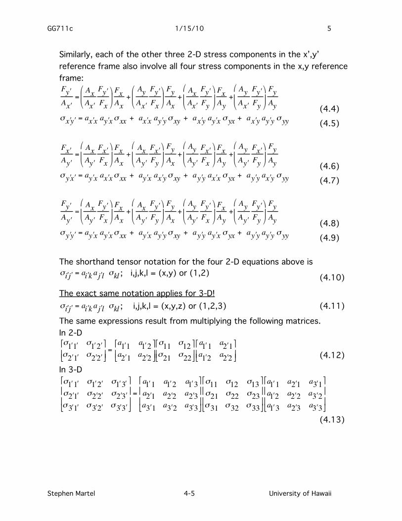
Similarly, each of the other three 2-D stress components in the x’,y’ reference frame also involve all four stress components in the x,y reference frame:
€
F ′ y A ′ x
=AxA ′ x
F ′ y Fx
FxAx
+AyA ′ x
F ′ y Fx
FyAx
+AxA ′ x
F ′ y Fy
FxAy
+AyA ′ x
F ′ y Fy
FyAy (4.4)
€
σ ′ x ′ y = a ′ x x a ′ y xσ xx + a ′ x x a ′ y yσ xy + a ′ x y a ′ y x σ yx + a ′ x y a ′ y y σ yy (4.5)
€
F ′ x A ′ y
=AxA ′ y
F ′ x Fx
FxAx
+AxA ′ y
F ′ x Fy
FyAx
+AyA ′ y
F ′ x Fx
FxAy
+AyA ′ y
F ′ x Fy
FyAy (4.6)
€
σ ′ y ′ x = a ′ y x a ′ x xσ xx + a ′ y x a ′ x yσ xy + a ′ y y a ′ x x σ yx + a ′ y y a ′ x y σ yy (4.7)
€
F ′ y A ′ y
=AxA ′ y
F ′ y Fx
FxAx
+AxA ′ y
F ′ y Fy
FyAx
+AyA ′ y
F ′ y Fx
FxAy
+AyA ′ y
F ′ y Fy
FyAy (4.8)
€
σ ′ y ′ y = a ′ y x a ′ y xσ xx + a ′ y x a ′ y yσ xy + a ′ y y a ′ y x σ yx + a ′ y y a ′ y y σ yy (4.9)
The shorthand tensor notation for the four 2-D equations above is
€
σ ′ i ′ j = a ′ i k a ′ j l σkl ; i,j,k,l = (x,y) or (1,2) (4.10)
The exact same notation applies for 3-D!
€
σ ′ i ′ j = a ′ i k a ′ j l σkl ; i,j,k,l = (x,y,z) or (1,2,3) (4.11) The same expressions result from multiplying the following matrices. In 2-D
€
σ ′ 1 ′ 1 σ ′ 1 ′ 2 σ ′ 2 ′ 1 σ ′ 2 ′ 2
=
a ′ 1 1 a ′ 1 2a ′ 2 1 a ′ 2 2
σ11 σ12σ21 σ22
a ′ 1 1 a ′ 2 1a ′ 1 2 a ′ 2 2
(4.12)
In 3-D
€
σ ′ 1 ′ 1 σ ′ 1 ′ 2 σ ′ 1 ′ 3 σ ′ 2 ′ 1 σ ′ 2 ′ 2 σ ′ 2 ′ 3 σ ′ 3 ′ 1 σ ′ 3 ′ 2 σ ′ 3 ′ 3
=
a ′ 1 1 a ′ 1 2 a ′ 1 3a ′ 2 1 a ′ 2 2 a ′ 2 3a ′ 3 1 a ′ 3 2 a ′ 3 3
σ11 σ12 σ13σ21 σ22 σ23σ31 σ32 σ33
a ′ 1 1 a ′ 2 1 a ′ 3 1a ′ 1 2 a ′ 2 2 a ′ 3 2a ′ 1 3 a ′ 2 3 a ′ 3 3
(4.13)
GG711c 1/15/10 6
Stephen Martel 4-6 University of Hawaii
In general
€
σ ′ i ′ j [ ] = a[ ] σ[ ] a[ ]T Works for either 2-D or 3-D! (4.14)
Advantages of Mohr circle approach over tensor/matrix approach
1 Gives a geometric meaning to stress relationships. 2 Can do stress rotation problems in your head.
Advantages of tensor or matrix approach over Mohr circle approach
1 The physical underpinning behind how stresses transform is explicit; it is not obvious with a Mohr circle construction. First, the notion that all members of a stress tensor are involved in the transformation is more straightforward than with a Mohr circle. Second, the two rotation terms ai’k and aj’l reflect (a) the rotation of the area that the stress components act on, and (b) the rotation of the direction that the components act in, so the tendency to incorrectly consider stress as a force is reduced; the tensor quality of stresses is more apparent.
2 The double angle expressions in Mohr circle, which can be difficult to remember and work with, are not present here.
3 Easier to address with a computer or a calculator. 4 Can apply just as easy to 3-D as 2-D; far more useful for 3-D problems
than Mohr diagrams. 5 Powerful methods of linear algebra exist for finding the magnitudes of the
principal stresses ("eigenvalues") and the direction of the principal stresses ("eigenvectors), so the underlying nature of the stress field is easier to identify; this is especially important in 3-D.
GG711c 1/15/10 7
Stephen Martel 4-7 University of Hawaii
GG711c 1/15/10 8
Stephen Martel 4-8 University of Hawaii
GG711c 1/15/10 9
Stephen Martel 4-9 University of Hawaii
GG711c 1/15/10 10
Stephen Martel 4-10 University of Hawaii
GG711c 1/15/10 11
Stephen Martel 4-11 University of Hawaii
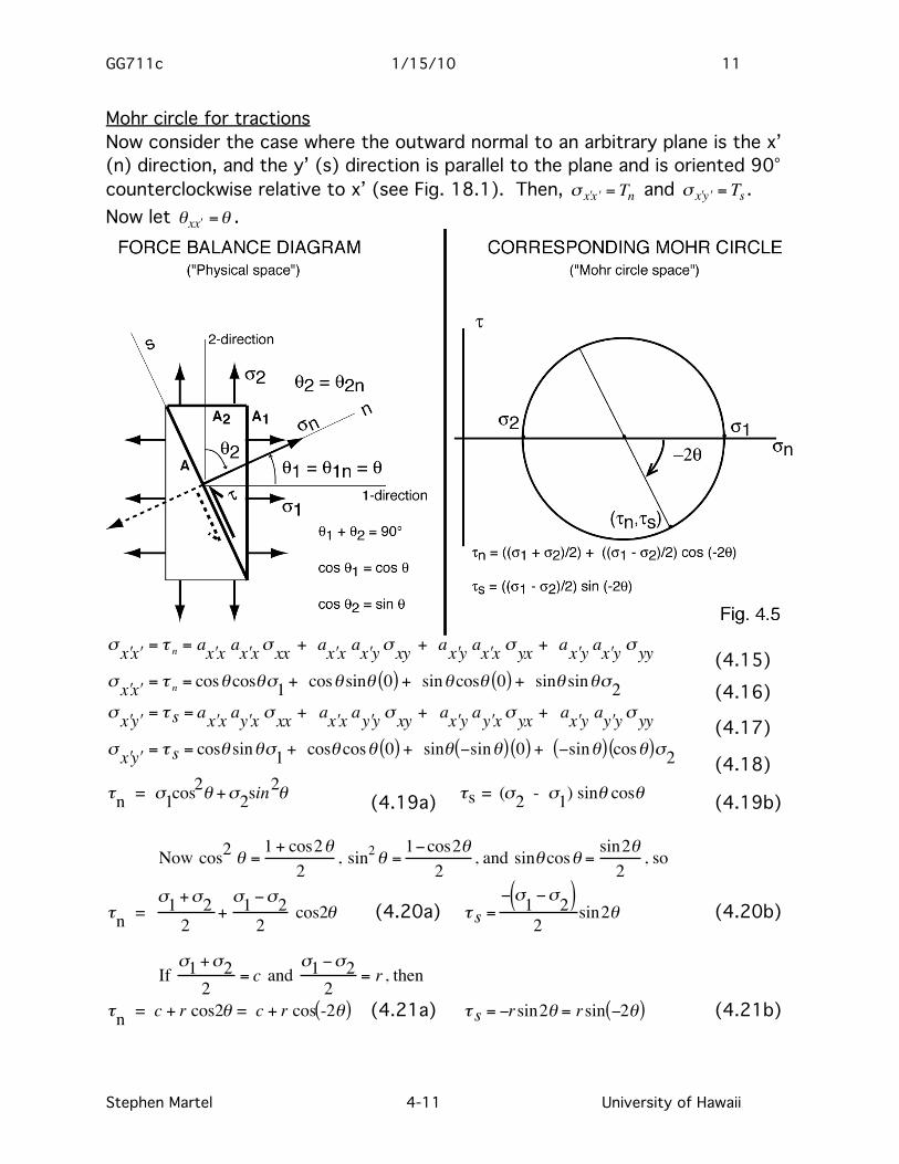
Mohr circle for tractions Now consider the case where the outward normal to an arbitrary plane is the x’ (n) direction, and the y’ (s) direction is parallel to the plane and is oriented 90° counterclockwise relative to x’ (see Fig. 18.1). Then,
€
σ ′ x ′ x = Tn and
€
σ ′ x ′ y = Ts . Now let
€
θx ′ x =θ .
€
σ ′ x ′ x = τ n = a ′ x x a ′ x xσ xx + a ′ x x a ′ x yσ xy + a ′ x y a ′ x x σ yx + a ′ x y a ′ x y σ yy (4.15)
€
σ ′ x ′ x = τ n = cosθ cosθσ1 + cosθ sinθ 0( ) + sinθ cosθ 0( ) + sinθ sinθσ2 (4.16)
€
σ ′ x ′ y = τ s = a ′ x x a ′ y x σ xx + a ′ x x a ′ y y σ xy + a ′ x y a ′ y xσ yx + a ′ x y a ′ y yσ yy (4.17)
€
σ ′ x ′ y = τ s = cosθ sinθσ1 + cosθ cosθ 0( ) + sinθ −sinθ( ) 0( ) + −sinθ( ) cosθ( )σ2 (4.18)
€
τn = σ1cos2θ +σ2sin2θ (4.19a)
€
τs = (σ2 - σ1) sinθ cosθ (4.19b)
Now cos2 θ = 1 + cos2θ2
,
€
sin2θ =1−cos2θ
2, and
€
sinθ cosθ =sin2θ2
, so
€
τn = σ1 +σ2
2+σ1 −σ2
2 cos2θ (4.20a)
€
τ s =− σ1 −σ2( )
2sin2θ (4.20b)
If
€
σ1 +σ22
= c and
€
σ1 −σ22
= r , then
€
τn = c + r cos2θ = c + r cos -2θ( ) (4.21a)
€
τ s = −rsin2θ = rsin −2θ( ) (4.21b)
GG711c 1/15/10 12
Stephen Martel 4-12 University of Hawaii
These are the equations of a Mohr circle for tractions that relates the tractions on planes of different orientation. Its center “c” is the mean normal stress, and the absolute value of “r” is the magnitude of the maximum shear stress (the circle radius). The term
€
σ1 is the most tensile stress. If in "physical space" we measure angle +θ about the z-axis using a right-hand rule, then on a Mohr circle relying on a tensor stress convention we use double angles of -2θ. As θ goes counterclockwise from 0 to 180°, -2θ goes from 0 to -360°; one complete clockwise circuit is made around the Mohr circle.
B Key points
1 θ = θ1 = θ1n = is the angle between the normal to the plane
€
σ1 acts on and the normal to the plane of interest.
2 The maximum shear stress is at θ = ±45° from
€
σ1
€
−2θ = 90o( )
3 The normal stress maximum is at θ = 0° from
€
σ1 (-2θ = 0°)
4 The normal stress minimum is at θ = 90° from
€
σ1 (-2θ = -180°)