6.776 High Speed Communication Circuits Lecture 2 ... · Balanced modulator Balanced modulator-90o...
46
6.776 High Speed Communication Circuits Lecture 2 Transceiver Architectures Massachusetts Institute of Technology February 3, 2005 Copyright © 2005 by H.-S. Lee and M. H. Perrott
Transcript of 6.776 High Speed Communication Circuits Lecture 2 ... · Balanced modulator Balanced modulator-90o...
6.776High Speed Communication Circuits
Lecture 2Transceiver Architectures
Massachusetts Institute of TechnologyFebruary 3, 2005
Copyright © 2005 by H.-S. Lee and M. H. Perrott
H.-S. Lee & M.H. Perrott MIT OCW
Transceivers for Amplitude Modulation
H.-S. Lee & M.H. Perrott MIT OCW
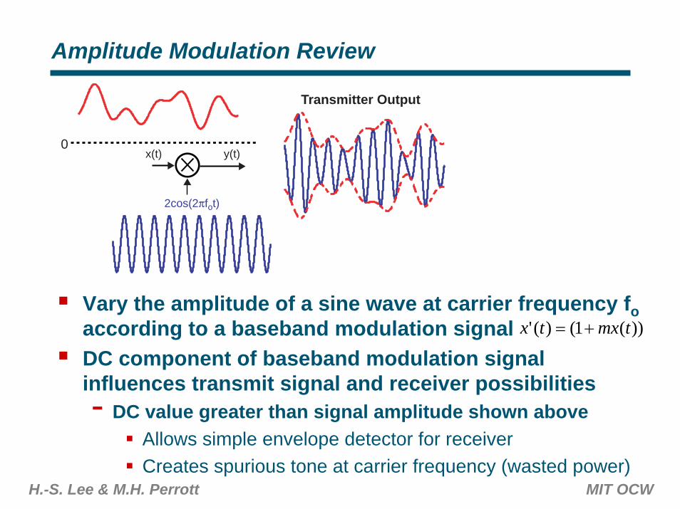
Amplitude Modulation Review
2cos(2πfot)
y(t)
Transmitter Output
x(t)0
Vary the amplitude of a sine wave at carrier frequency foaccording to a baseband modulation signal DC component of baseband modulation signal influences transmit signal and receiver possibilities- DC value greater than signal amplitude shown above
Allows simple envelope detector for receiverCreates spurious tone at carrier frequency (wasted power)
))(1()(' tmxtx +=
H.-S. Lee & M.H. Perrott MIT OCW
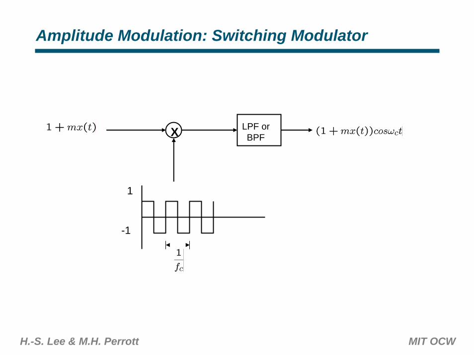
Amplitude Modulation: Switching Modulator
X LPF orBPF
1
-1
H.-S. Lee & M.H. Perrott MIT OCW
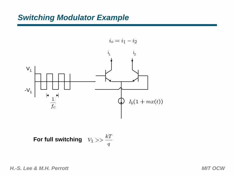
Switching Modulator Example
i1 i2
V1
-V1
For full switching
H.-S. Lee & M.H. Perrott MIT OCW
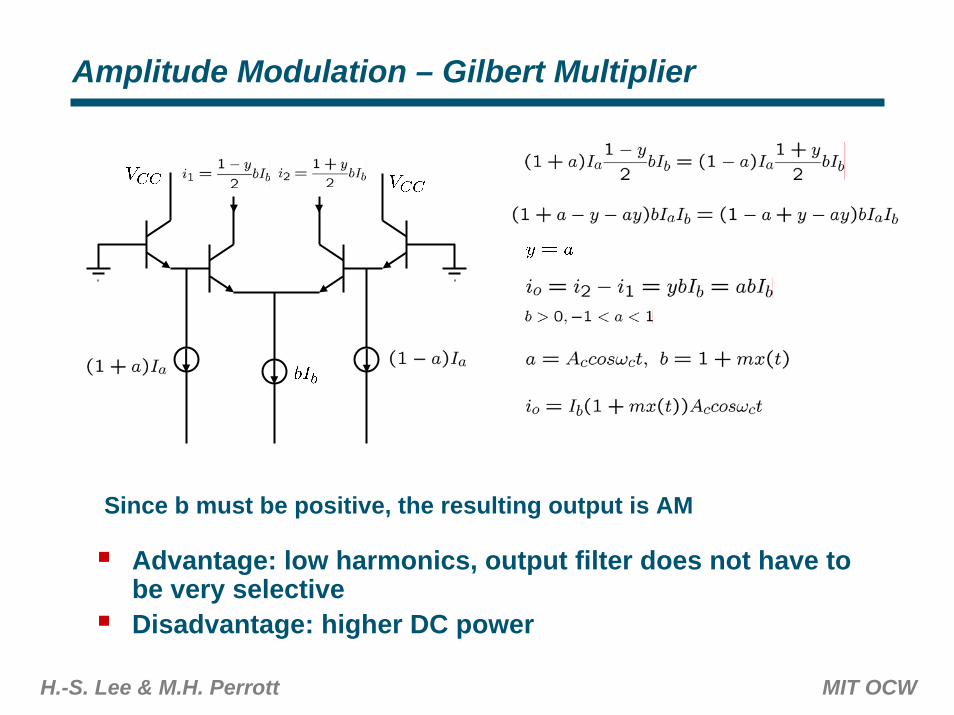
Amplitude Modulation – Gilbert Multiplier
Since b must be positive, the resulting output is AM
Advantage: low harmonics, output filter does not have to be very selectiveDisadvantage: higher DC power
H.-S. Lee & M.H. Perrott MIT OCW
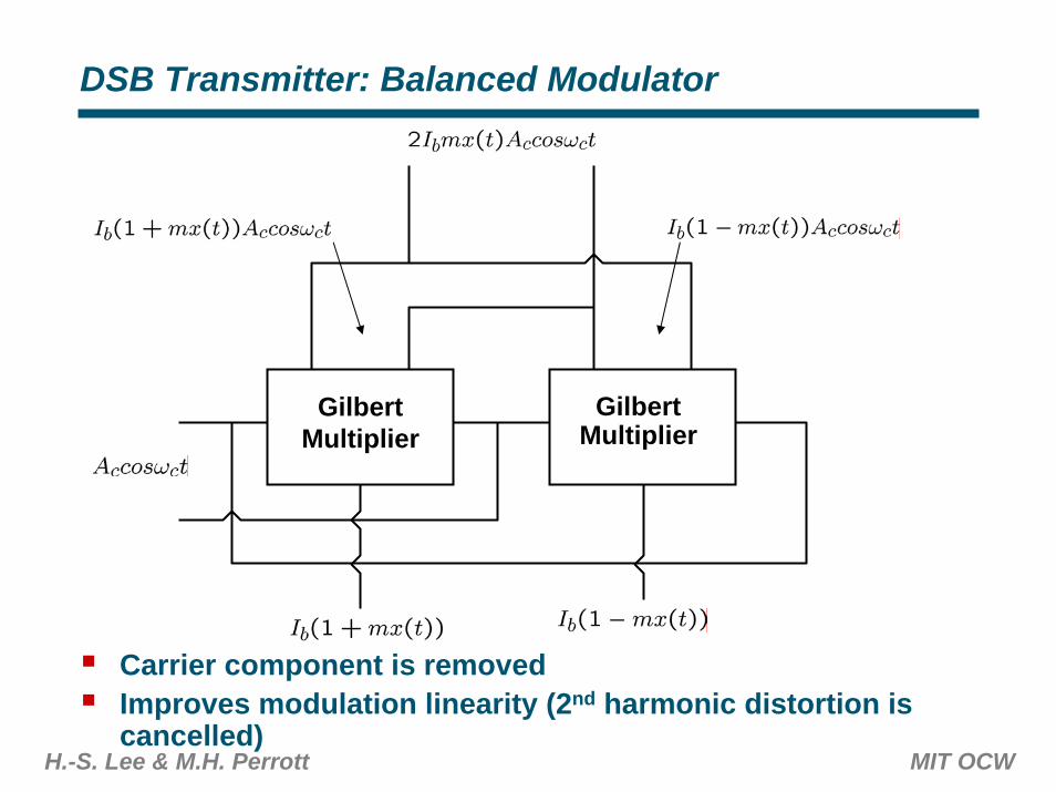
DSB Transmitter: Balanced Modulator
GilbertMultiplier
GilbertMultiplier
Carrier component is removedImproves modulation linearity (2nd harmonic distortion is cancelled)
H.-S. Lee & M.H. Perrott MIT OCW
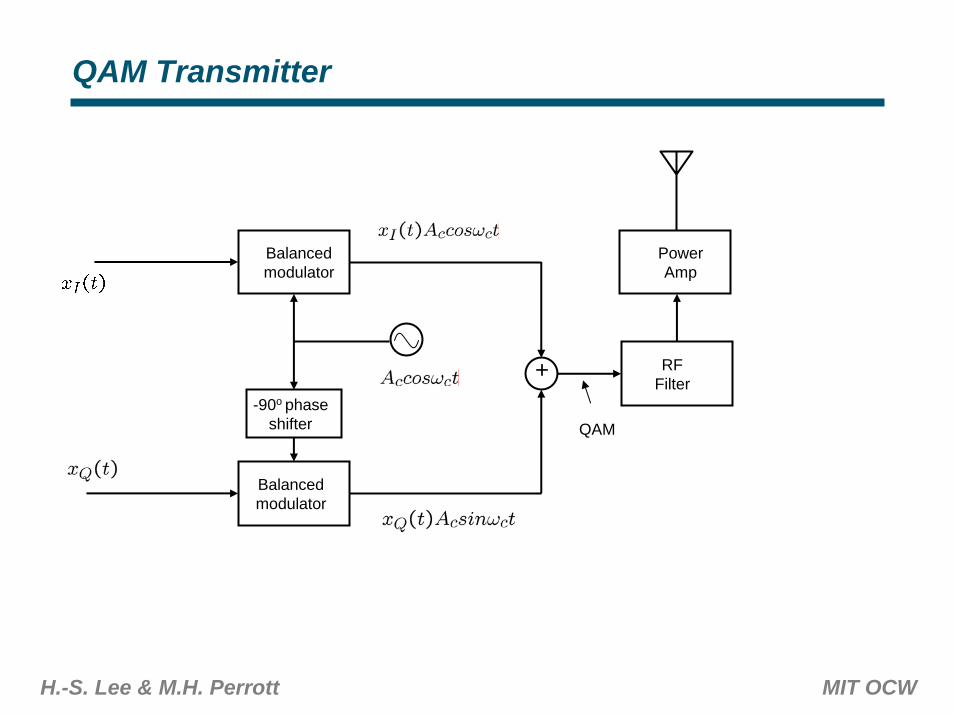
QAM Transmitter
Balancedmodulator
Balancedmodulator
-90o phaseshifter
RFFilter
PowerAmp
+
QAM
H.-S. Lee & M.H. Perrott MIT OCW
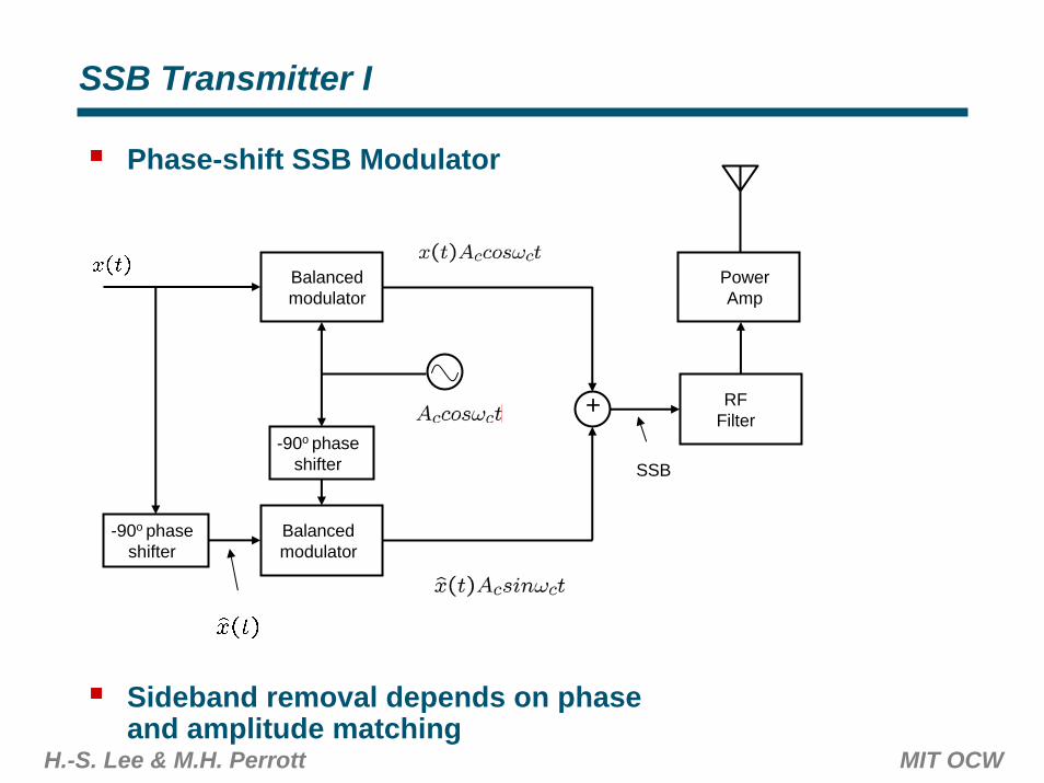
SSB Transmitter I
Phase-shift SSB Modulator
Sideband removal depends on phase and amplitude matching
Balancedmodulator
Balancedmodulator
-90o phaseshifter
-90o phaseshifter
RFFilter
PowerAmp
+
SSB
H.-S. Lee & M.H. Perrott MIT OCW
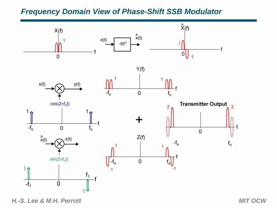
Frequency Domain View of Phase-Shift SSB Modulator
H.-S. Lee & M.H. Perrott MIT OCW
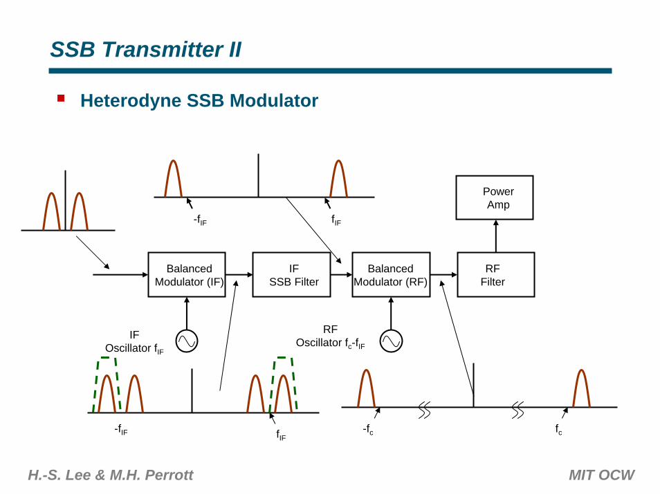
SSB Transmitter II
Heterodyne SSB Modulator
BalancedModulator (IF)
BalancedModulator (RF)
IFSSB Filter
RFFilter
PowerAmp
IFOscillator fIF
RFOscillator fc-fIF
fIFfc
fIF-fIF
-fIF -fc
H.-S. Lee & M.H. Perrott MIT OCW
Heterodyne Transmitter
Sideband filtering requires high selectivitySideband filtering is thus easier at lower IF frequency than at RF freqeuency (for example, at IF frequencies, SAW filters offer very high selectivity, low insertion loss, and low noise figure. They are relatively cheap, too)Same issues apply to receivers (not just for SSB receiever for that matter). ‘Superheterodyne’ receivers have been dominant for decades for the same reason.Requires two oscillators
H.-S. Lee & M.H. Perrott MIT OCW
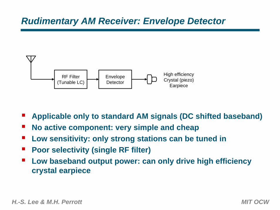
Rudimentary AM Receiver: Envelope Detector
RF Filter(Tunable LC)
EnvelopeDetector
High efficiencyCrystal (piezo)
Earpiece
Applicable only to standard AM signals (DC shifted baseband)No active component: very simple and cheapLow sensitivity: only strong stations can be tuned inPoor selectivity (single RF filter)Low baseband output power: can only drive high efficiency crystal earpiece
H.-S. Lee & M.H. Perrott MIT OCW
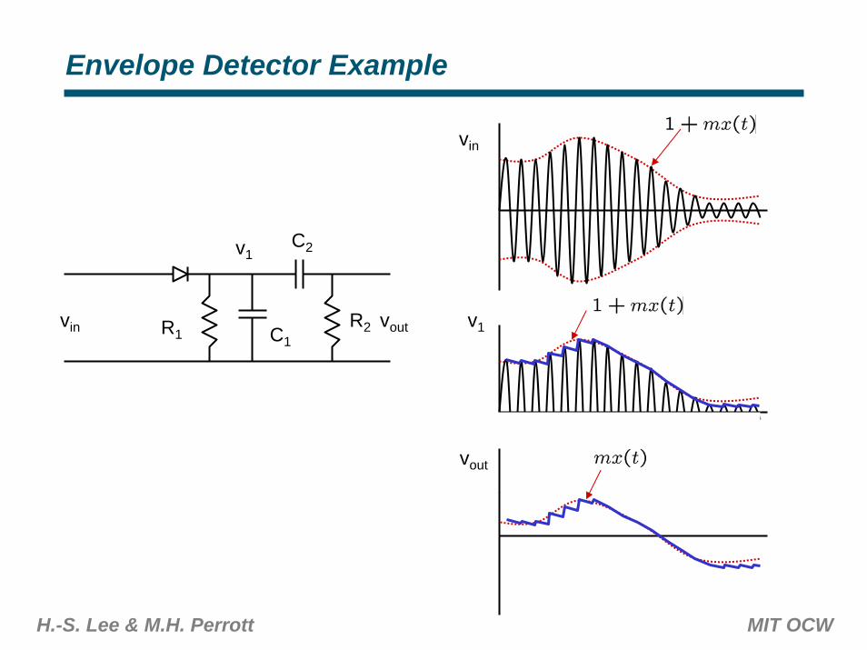
Envelope Detector Example
vin
vout
v1
C2v1
vin R2 voutR1 C1
H.-S. Lee & M.H. Perrott MIT OCW
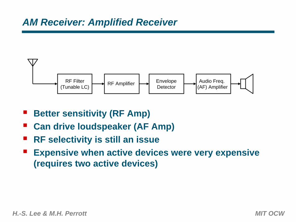
AM Receiver: Amplified Receiver
RF Filter(Tunable LC)
EnvelopeDetector
RF Amplifier Audio Freq. (AF) Amplifier
Better sensitivity (RF Amp)Can drive loudspeaker (AF Amp)RF selectivity is still an issueExpensive when active devices were very expensive (requires two active devices)
H.-S. Lee & M.H. Perrott MIT OCW
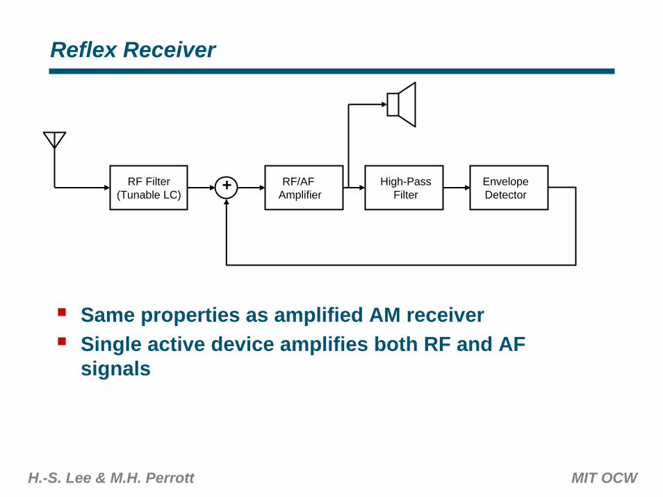
Reflex Receiver
RF Filter(Tunable LC)
EnvelopeDetector
RF/AFAmplifier
High-PassFilter
+
Same properties as amplified AM receiverSingle active device amplifies both RF and AF signals
H.-S. Lee & M.H. Perrott MIT OCW
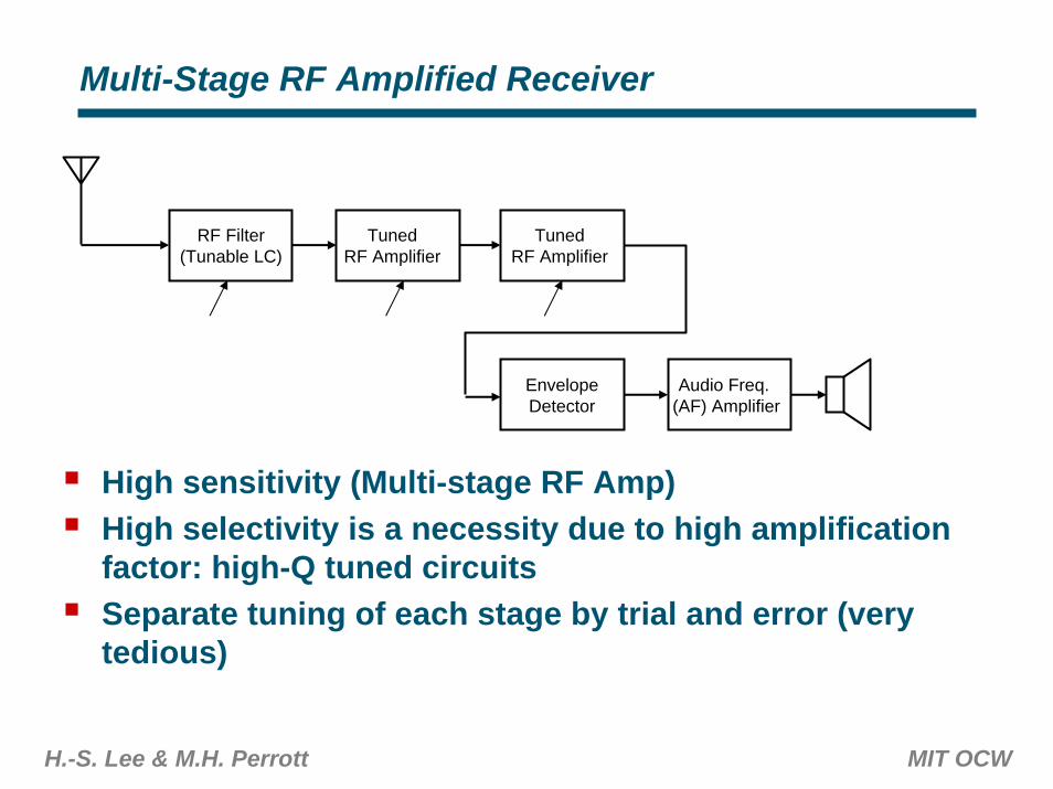
Multi-Stage RF Amplified Receiver
RF Filter(Tunable LC)
EnvelopeDetector
TunedRF Amplifier
Audio Freq. (AF) Amplifier
TunedRF Amplifier
High sensitivity (Multi-stage RF Amp)High selectivity is a necessity due to high amplification factor: high-Q tuned circuitsSeparate tuning of each stage by trial and error (very tedious)
H.-S. Lee & M.H. Perrott MIT OCW
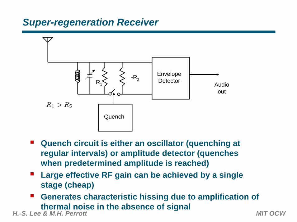
Super-regeneration Receiver
EnvelopeDetectorR1
-R2
Quench
Audioout
Quench circuit is either an oscillator (quenching at regular intervals) or amplitude detector (quenches when predetermined amplitude is reached)Large effective RF gain can be achieved by a single stage (cheap)Generates characteristic hissing due to amplification of thermal noise in the absence of signal
H.-S. Lee & M.H. Perrott MIT OCW
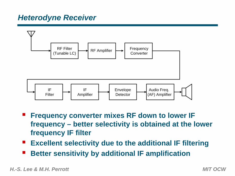
Heterodyne Receiver
RF Filter(Tunable LC)
EnvelopeDetector
RF Amplifier
Audio Freq. (AF) Amplifier
FrequencyConverter
IFFilter
IFAmplifier
Frequency converter mixes RF down to lower IF frequency – better selectivity is obtained at the lower frequency IF filterExcellent selectivity due to the additional IF filteringBetter sensitivity by additional IF amplification
H.-S. Lee & M.H. Perrott MIT OCW
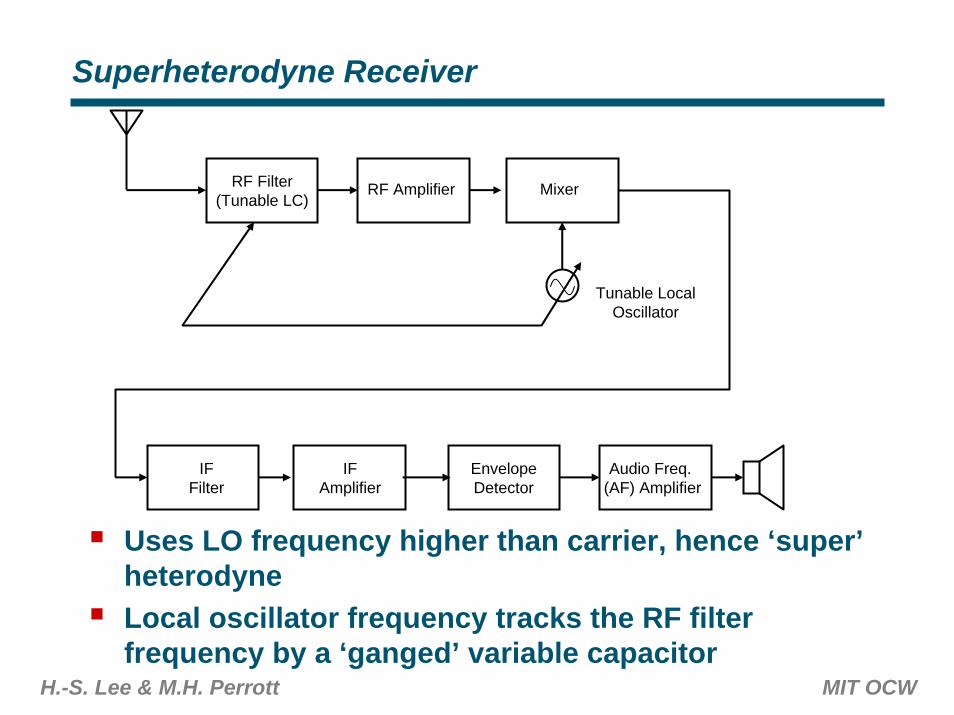
Superheterodyne Receiver
RF Filter(Tunable LC)
EnvelopeDetector
RF Amplifier
Audio Freq. (AF) Amplifier
Mixer
IFFilter
Tunable LocalOscillator
IFAmplifier
Uses LO frequency higher than carrier, hence ‘super’heterodyneLocal oscillator frequency tracks the RF filter frequency by a ‘ganged’ variable capacitor
H.-S. Lee & M.H. Perrott MIT OCW
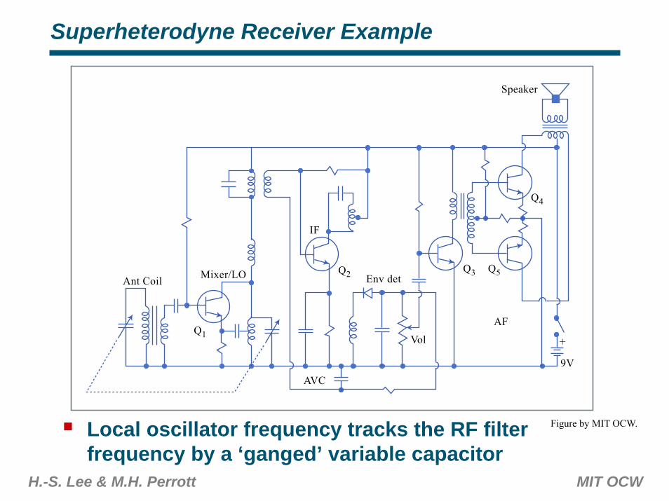
Superheterodyne Receiver Example
Local oscillator frequency tracks the RF filter frequency by a ‘ganged’ variable capacitor
Ant Coil
AVC
Mixer/LO
IF
AF
9V
+Vol
Env det
Speaker
Q1
Q2 Q3
Q4
Q5
Figure by MIT OCW.
H.-S. Lee & M.H. Perrott MIT OCW
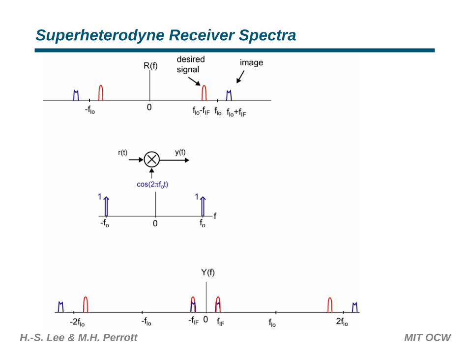
Superheterodyne Receiver Spectra
H.-S. Lee & M.H. Perrott MIT OCW
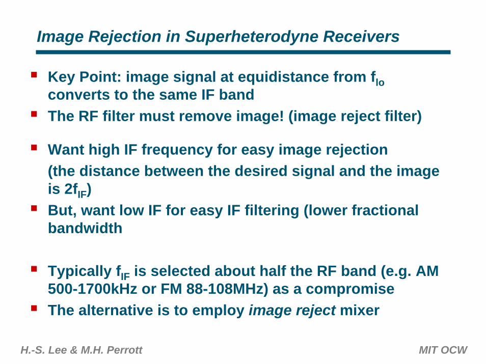
Image Rejection in Superheterodyne Receivers
Key Point: image signal at equidistance from floconverts to the same IF bandThe RF filter must remove image! (image reject filter)
Want high IF frequency for easy image rejection(the distance between the desired signal and the image is 2fIF)But, want low IF for easy IF filtering (lower fractional bandwidth
Typically fIF is selected about half the RF band (e.g. AM 500-1700kHz or FM 88-108MHz) as a compromiseThe alternative is to employ image reject mixer
H.-S. Lee & M.H. Perrott MIT OCW
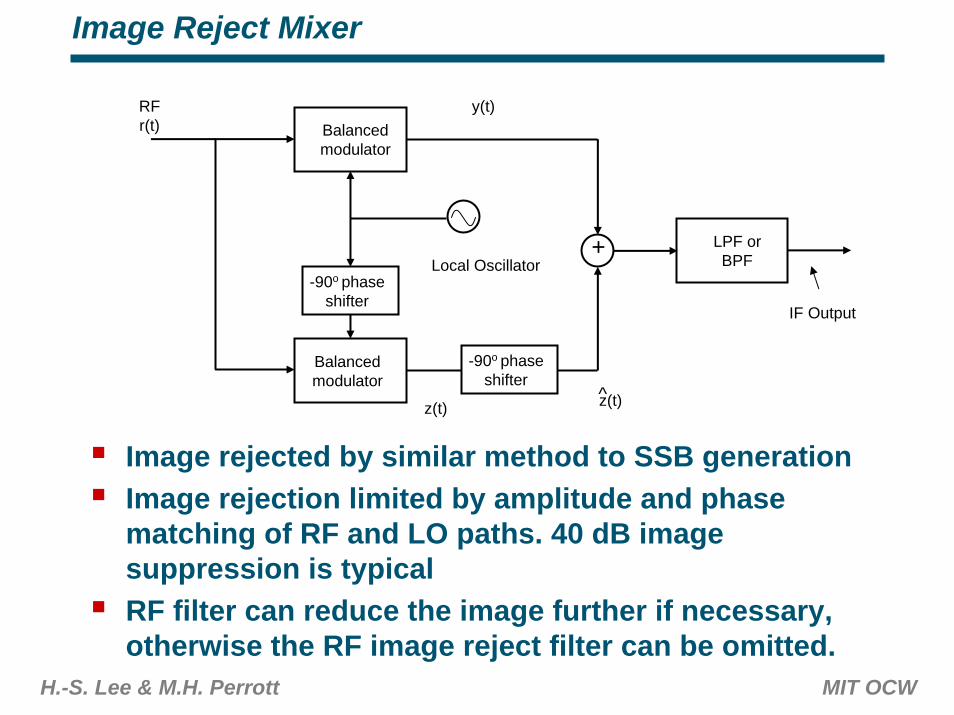
Image Reject Mixer
Balancedmodulator
Balancedmodulator
-90o phaseshifter
-90o phaseshifter
+
RF r(t)
Image rejected by similar method to SSB generationImage rejection limited by amplitude and phase matching of RF and LO paths. 40 dB image suppression is typicalRF filter can reduce the image further if necessary, otherwise the RF image reject filter can be omitted.
IF Output
Local OscillatorLPF orBPF
y(t)
z(t) z(t)^
H.-S. Lee & M.H. Perrott MIT OCW
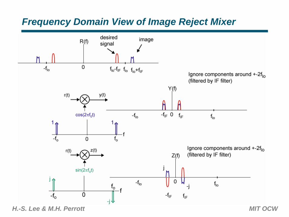
Frequency Domain View of Image Reject Mixer
H.-S. Lee & M.H. Perrott MIT OCW
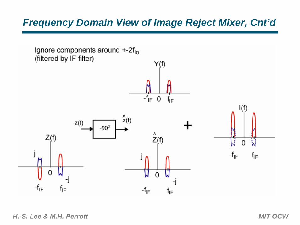
Frequency Domain View of Image Reject Mixer, Cnt’d
H.-S. Lee & M.H. Perrott MIT OCW
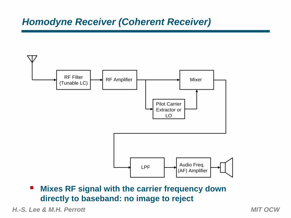
Homodyne Receiver (Coherent Receiver)
RF Filter(Tunable LC)
LPF
RF Amplifier
Audio Freq. (AF) Amplifier
Mixer
Pilot CarrierExtractor or
LO
Mixes RF signal with the carrier frequency down directly to baseband: no image to reject
H.-S. Lee & M.H. Perrott MIT OCW
Homodyne Receiver Cont’d
No local oscillator if pilot carrier is present – carrier extracted from the transmitted signal (carrier needs to be inserted in DSB or SSB, so not compatible with standard DSB or SSB transmission)Otherwise, a local oscillator at carrier frequency is needed (see direct conversion receiver later)Carrier extractor can be a narrowband filter, PLL, or an oscillator synchronized by the carrier signalA form of a direct conversion receiver: same advantages and issues
H.-S. Lee & M.H. Perrott MIT OCW
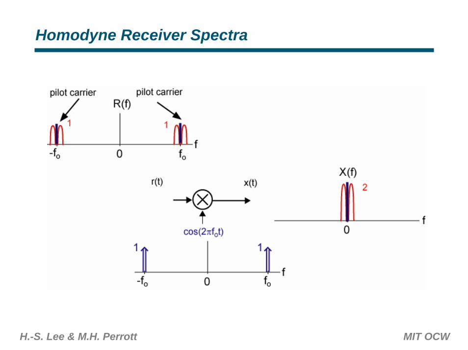
Homodyne Receiver Spectra
H.-S. Lee & M.H. Perrott MIT OCW
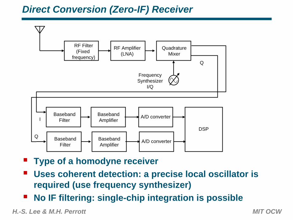
Direct Conversion (Zero-IF) Receiver
RF Filter(Fixed
frequency)
A/D converter
RF Amplifier(LNA)
DSP
QuadratureMixer
BasebandFilter
FrequencySynthesizer
I/Q
BasebandAmplifier
A/D converterBasebandFilter
BasebandAmplifier
I
Q
Q
Type of a homodyne receiverUses coherent detection: a precise local oscillator is required (use frequency synthesizer)No IF filtering: single-chip integration is possible
H.-S. Lee & M.H. Perrott MIT OCW
Direct Conversion (Zero-IF) Receiver
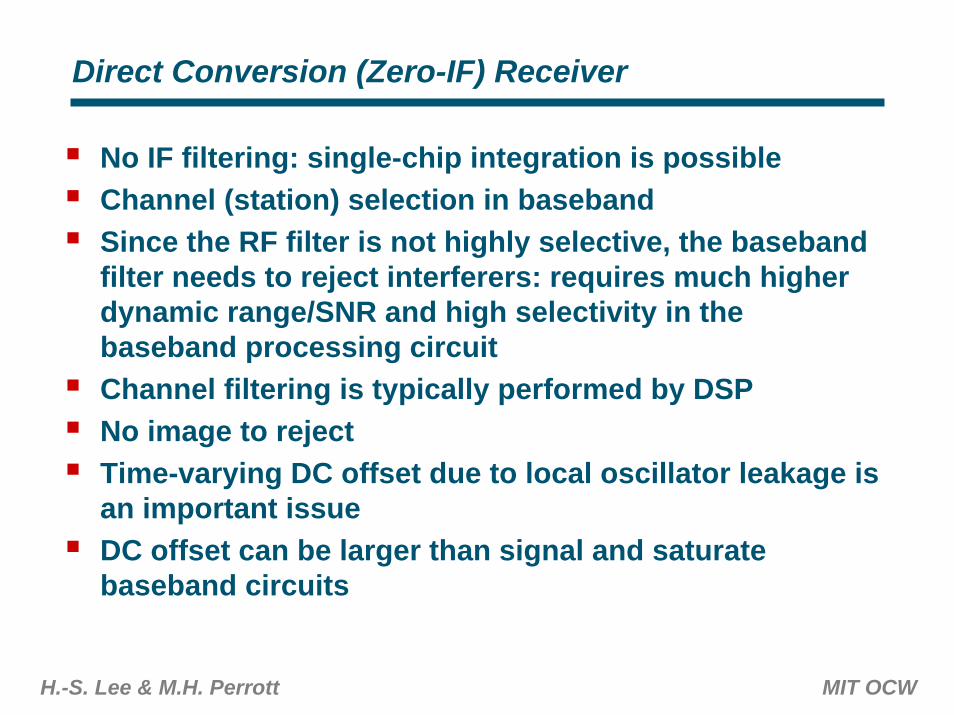
No IF filtering: single-chip integration is possibleChannel (station) selection in basebandSince the RF filter is not highly selective, the basebandfilter needs to reject interferers: requires much higher dynamic range/SNR and high selectivity in the baseband processing circuitChannel filtering is typically performed by DSPNo image to rejectTime-varying DC offset due to local oscillator leakage is an important issueDC offset can be larger than signal and saturate baseband circuits
H.-S. Lee & M.H. Perrott MIT OCW
Double Conversion Receiver
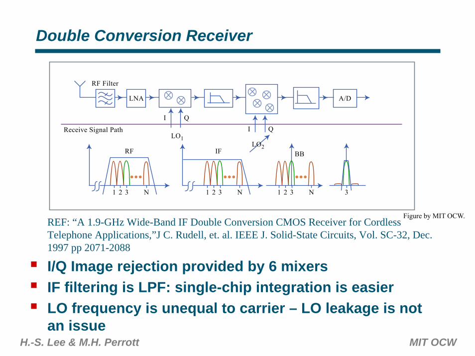
REF: “A 1.9-GHz Wide-Band IF Double Conversion CMOS Receiver for Cordless Telephone Applications,”J C. Rudell, et. al. IEEE J. Solid-State Circuits, Vol. SC-32, Dec. 1997 pp 2071-2088
I/Q Image rejection provided by 6 mixersIF filtering is LPF: single-chip integration is easierLO frequency is unequal to carrier – LO leakage is not an issue
LNA
RF Filter
RF
1 2 3 N
Receive Signal Path
A/D
I QI Q
LO1LO2
IF
1 2 3 N
BB
1 2 3 N 3
Figure by MIT OCW.
H.-S. Lee & M.H. Perrott MIT OCW
Image Rejection in Double Conversion Receiver
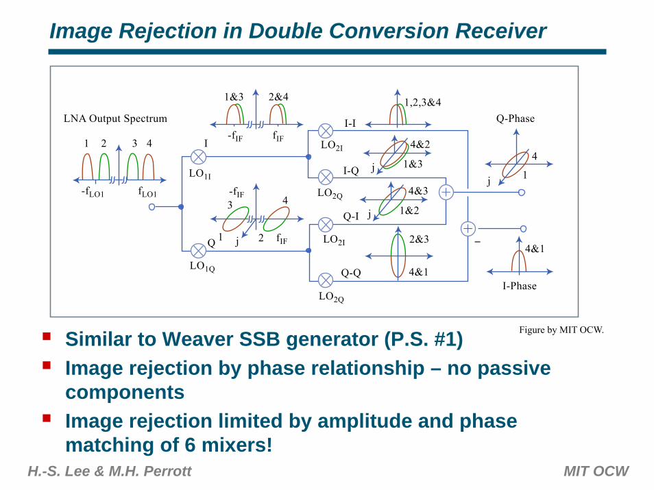
Similar to Weaver SSB generator (P.S. #1)Image rejection by phase relationship – no passive componentsImage rejection limited by amplitude and phase matching of 6 mixers!
1 2 3 4
LNA Output Spectrum
-fLO1
LO1Q
LO1I
LO2Q
LO2I -
LO2I
LO2QfLO1
1&3 2&4
-fIF
-fIF
fIF
fIF
1,2,3&4
I-I
I-Q
Q-I
Q-Q
Q-Phase
4&1
1
4
j
I-Phase
4&2
1&3j
4&3
1&24
2
3
1
I
Q
j
j 2&3
4&1
+
+
Figure by MIT OCW.
H.-S. Lee & M.H. Perrott MIT OCW
Low-IF Receiver
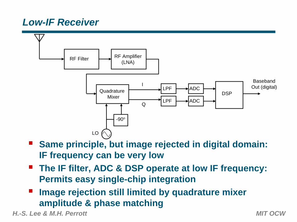
Same principle, but image rejected in digital domain: IF frequency can be very lowThe IF filter, ADC & DSP operate at low IF frequency: Permits easy single-chip integrationImage rejection still limited by quadrature mixer amplitude & phase matching
RF Filter RF Amplifier(LNA)
QuadratureMixer
-90o
I
Q
LPF
LPF
ADC
ADCDSP
BasebandOut (digital)
LO
Transceivers for Constant Envelope Modulation
H.-S. Lee & M.H. Perrott MIT OCW
H.-S. Lee & M.H. Perrott MIT OCW
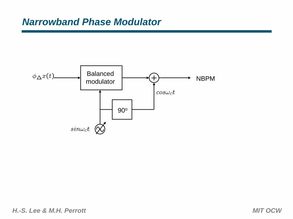
Narrowband Phase Modulator
Balancedmodulator
90o
NBPM
H.-S. Lee & M.H. Perrott MIT OCW
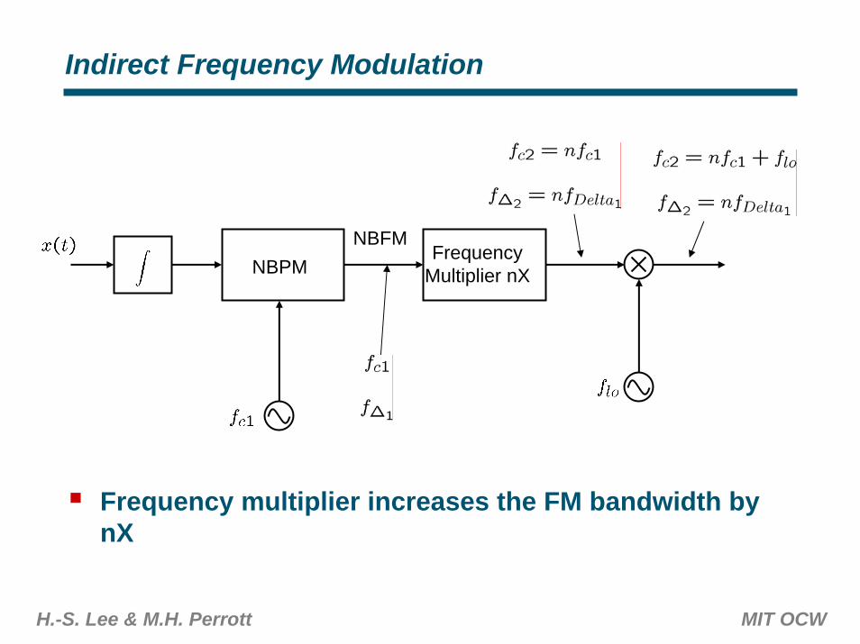
Indirect Frequency Modulation
NBPMFrequency
Multiplier nX
NBFM
Frequency multiplier increases the FM bandwidth by nX
H.-S. Lee & M.H. Perrott MIT OCW
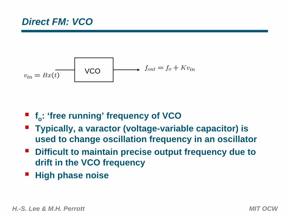
Direct FM: VCO
VCO
fo: ‘free running’ frequency of VCOTypically, a varactor (voltage-variable capacitor) is used to change oscillation frequency in an oscillatorDifficult to maintain precise output frequency due to drift in the VCO frequencyHigh phase noise
H.-S. Lee & M.H. Perrott MIT OCW
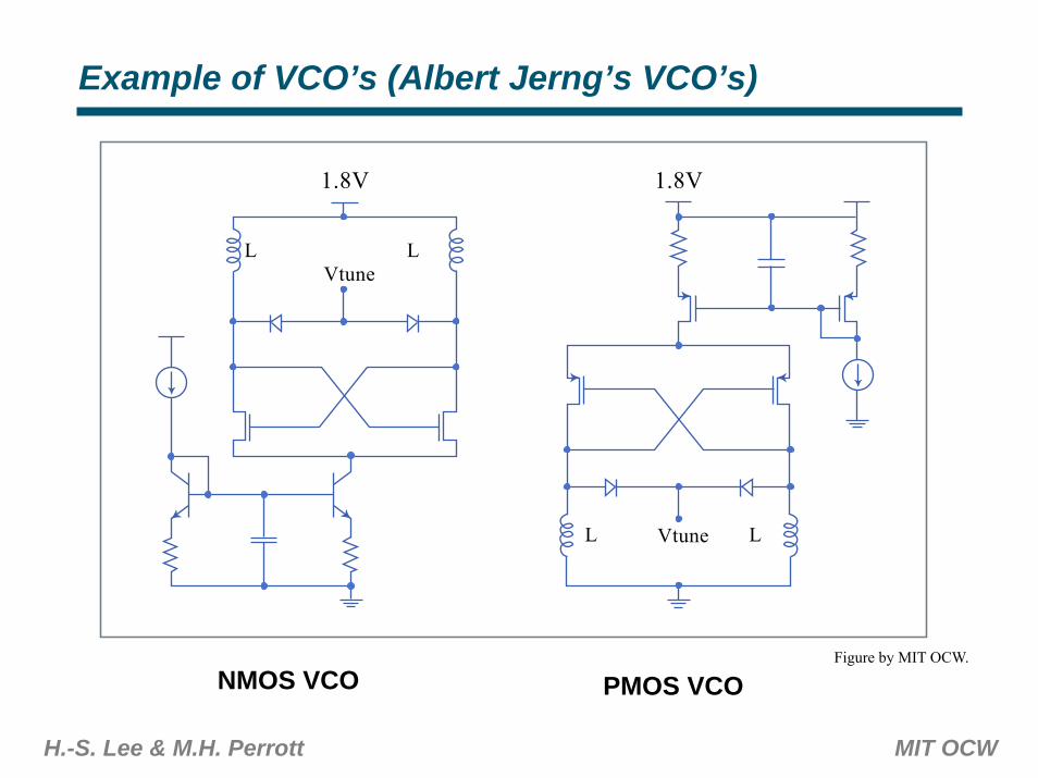
Example of VCO’s (Albert Jerng’s VCO’s)
NMOS VCO PMOS VCOFigure by MIT OCW.
1.8V 1.8V
L
L L
LVtune
Vtune
H.-S. Lee & M.H. Perrott MIT OCW
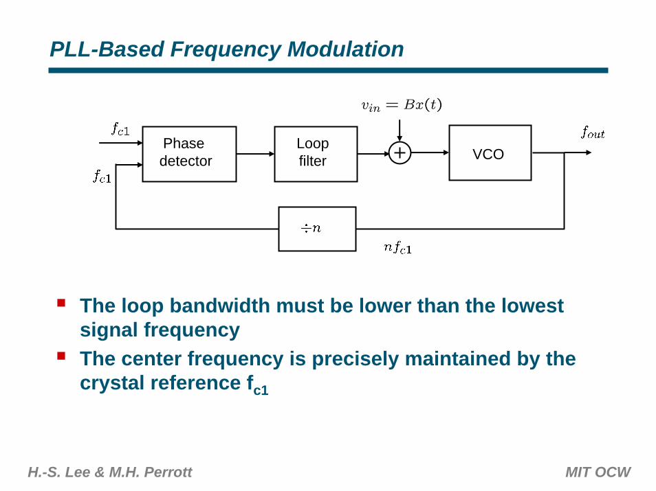
PLL-Based Frequency Modulation
Phase detector
Loopfilter VCO
The loop bandwidth must be lower than the lowest signal frequencyThe center frequency is precisely maintained by the crystal reference fc1

H.-S. Lee & M.H. Perrott MIT OCW
Digital Frequency Modulation Using Fractional-N Synthesizer
Phase detector
Loopfilter VCO
Digital ∆Σmodulator
(digital)
1-bitoutput
Modulo n/n+1 divider is duty-cycle modulated by the signalInput signal is ∆Σ modulated to push quantization noise out of loop bandwidth
H.-S. Lee & M.H. Perrott MIT OCW
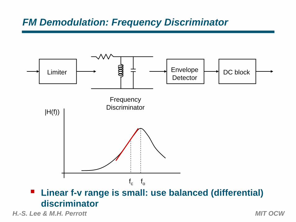
FM Demodulation: Frequency Discriminator
Limiter EnvelopeDetector
DC block
FrequencyDiscriminator
|H(f))
Linear f-v range is small: use balanced (differential) discriminator
fc fo
H.-S. Lee & M.H. Perrott MIT OCW
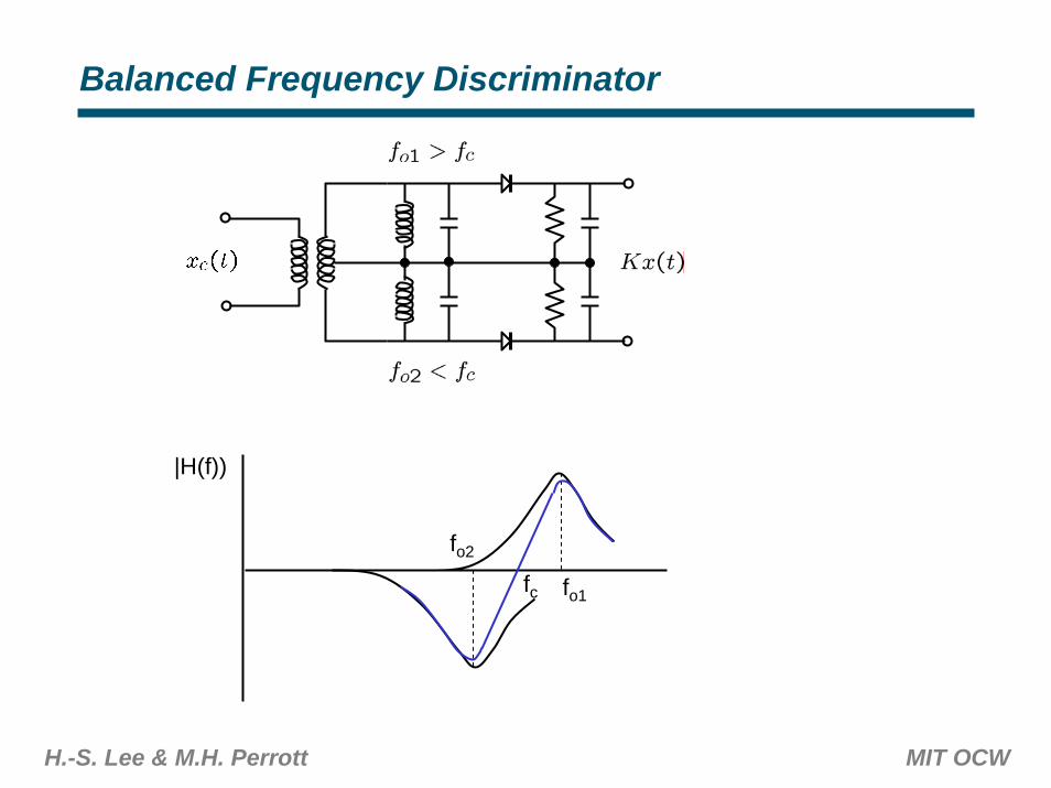
Balanced Frequency Discriminator
|H(f))
fo1fc
fo2
H.-S. Lee & M.H. Perrott MIT OCW
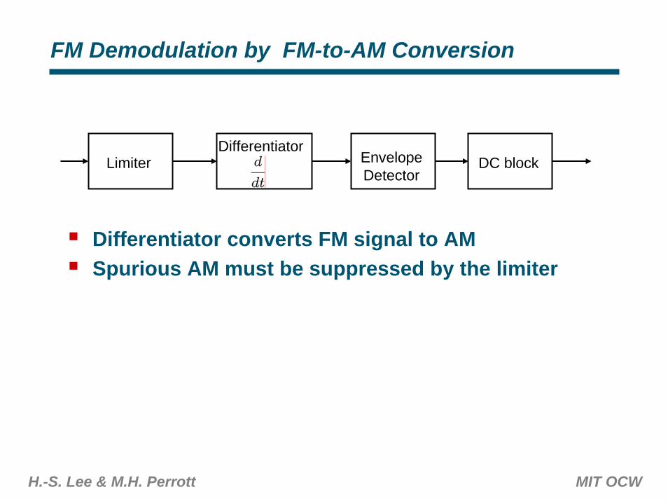
FM Demodulation by FM-to-AM Conversion
LimiterDifferentiator
EnvelopeDetector
DC block
Differentiator converts FM signal to AMSpurious AM must be suppressed by the limiter
H.-S. Lee & M.H. Perrott MIT OCW
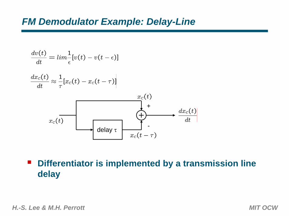
FM Demodulator Example: Delay-Line
delay τ
+
-
Differentiator is implemented by a transmission line delay
H.-S. Lee & M.H. Perrott MIT OCW
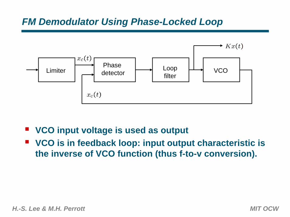
FM Demodulator Using Phase-Locked Loop
LimiterPhase detector
Loopfilter
VCO
VCO input voltage is used as outputVCO is in feedback loop: input output characteristic is the inverse of VCO function (thus f-to-v conversion).

![AComparisonofthe α2/3/5SelectivePositiveAllosteric ...downloads.hindawi.com/journals/aps/2011/608912.pdfand the efficacy of the α2/3/5 selective positive allosteric modulator(PAM)L-838,417[5]inaratchronicconstriction](https://static.fdocument.org/doc/165x107/6053dedfab49ec0dcb5f2bfc/acomparisonofthe-235selectivepositiveallosteric-and-the-eifcacy-of-the.jpg)