2 ai rtd hf analog electronic module (6es7134 4nb51-0ab0) - 2ai rtd hf analog electronic module...
8
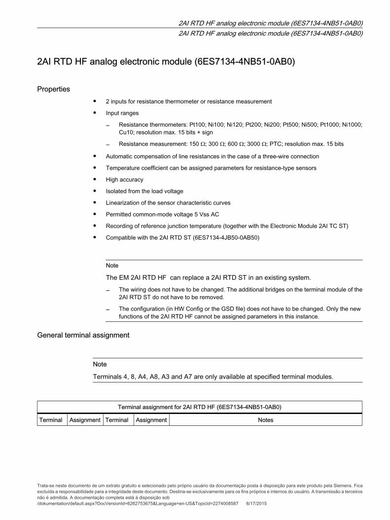
2AI RTD HF analog electronic module (6ES7134-4NB51-0AB0) Properties • 2 inputs for resistance thermometer or resistance measurement • Input ranges ― Resistance thermometers: Pt100; Ni100; Ni120; Pt200; Ni200; Pt500; Ni500; Pt1000; Ni1000; Cu10; resolution max. 15 bits + sign ― Resistance measurement: 150 Ω; 300 Ω; 600 Ω; 3000 Ω; PTC; resolution max. 15 bits • Automatic compensation of line resistances in the case of a three-wire connection • Temperature coefficient can be assigned parameters for resistance-type sensors • High accuracy • Isolated from the load voltage • Linearization of the sensor characteristic curves • Permitted common-mode voltage 5 Vss AC • Recording of reference junction temperature (together with the Electronic Module 2AI TC ST) • Compatible with the 2AI RTD ST (6ES7134-4JB50-0AB50) Note The EM 2AI RTD HF can replace a 2AI RTD ST in an existing system. ― The wiring does not have to be changed. The additional bridges on the terminal module of the 2AI RTD ST do not have to be removed. ― The configuration (in HW Config or the GSD file) does not have to be changed. Only the new functions of the 2AI RTD HF cannot be assigned parameters in this instance. General terminal assignment Note Terminals 4, 8, A4, A8, A3 and A7 are only available at specified terminal modules. Terminal assignment for 2AI RTD HF (6ES7134-4NB51-0AB0) Terminal Assignment Terminal Assignment Notes 2AI RTD HF analog electronic module (6ES7134-4NB51-0AB0) 2AI RTD HF analog electronic module (6ES7134-4NB51-0AB0) Trata-se neste documento de um extrato gratuito e selecionado pelo próprio usuário da documentação posta à disposição para este produto pela Siemens. Fica excluída a responsabilidade para a integridade deste documento. Destina-se exclusivamente para os fins próprios e internos do usuário. A transmissão a terceiros não é admitida. A documentação completa está à disposição sob /dokumentation/default.aspx?DocVersionId=6262753675&Language=en-US&TopicId=2274008587 6/17/2015
-
Upload
joao-luiz-vilimavicius -
Category
Data & Analytics
-
view
190 -
download
2
Transcript of 2 ai rtd hf analog electronic module (6es7134 4nb51-0ab0) - 2ai rtd hf analog electronic module...
2AI RTD HF analog electronic module (6ES7134-4NB51-0AB0)
Properties
• 2 inputs for resistance thermometer or resistance measurement
• Input ranges
― Resistance thermometers: Pt100; Ni100; Ni120; Pt200; Ni200; Pt500; Ni500; Pt1000; Ni1000;Cu10; resolution max. 15 bits + sign
― Resistance measurement: 150 Ω; 300 Ω; 600 Ω; 3000 Ω; PTC; resolution max. 15 bits
• Automatic compensation of line resistances in the case of a three-wire connection
• Temperature coefficient can be assigned parameters for resistance-type sensors
• High accuracy
• Isolated from the load voltage
• Linearization of the sensor characteristic curves
• Permitted common-mode voltage 5 Vss AC
• Recording of reference junction temperature (together with the Electronic Module 2AI TC ST)
• Compatible with the 2AI RTD ST (6ES7134-4JB50-0AB50)
Note
The EM 2AI RTD HF can replace a 2AI RTD ST in an existing system.
― The wiring does not have to be changed. The additional bridges on the terminal module of the2AI RTD ST do not have to be removed.
― The configuration (in HW Config or the GSD file) does not have to be changed. Only the newfunctions of the 2AI RTD HF cannot be assigned parameters in this instance.
General terminal assignment
Note
Terminals 4, 8, A4, A8, A3 and A7 are only available at specified terminal modules.
Terminal assignment for 2AI RTD HF (6ES7134-4NB51-0AB0)
Terminal Assignment Terminal Assignment Notes
2AI RTD HF analog electronic module (6ES7134-4NB51-0AB0)2AI RTD HF analog electronic module (6ES7134-4NB51-0AB0)
Trata-se neste documento de um extrato gratuito e selecionado pelo próprio usuário da documentação posta à disposição para este produto pela Siemens. Ficaexcluída a responsabilidade para a integridade deste documento. Destina-se exclusivamente para os fins próprios e internos do usuário. A transmissão a terceirosnão é admitida. A documentação completa está à disposição sob/dokumentation/default.aspx?DocVersionId=6262753675&Language=en-US&TopicId=2274008587 6/17/2015
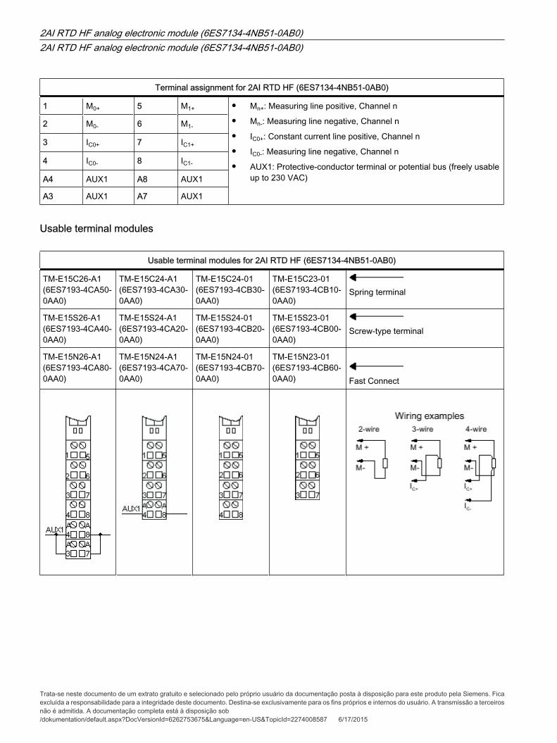
Terminal assignment for 2AI RTD HF (6ES7134-4NB51-0AB0)
1 M0+ 5 M1+ • Mn+: Measuring line positive, Channel n
• Mn-: Measuring line negative, Channel n
• IC0+: Constant current line positive, Channel n
• IC0-: Measuring line negative, Channel n
• AUX1: Protective-conductor terminal or potential bus (freely usableup to 230 VAC)
2 M0- 6 M1-
3 IC0+ 7 IC1+
4 IC0- 8 IC1-
A4 AUX1 A8 AUX1
A3 AUX1 A7 AUX1
Usable terminal modules
Usable terminal modules for 2AI RTD HF (6ES7134-4NB51-0AB0)
TM-E15C26-A1 (6ES7193-4CA50-0AA0)
TM-E15C24-A1 (6ES7193-4CA30-0AA0)
TM-E15C24-01 (6ES7193-4CB30-0AA0)
TM-E15C23-01 (6ES7193-4CB10-0AA0)
Spring terminal
TM-E15S26-A1 (6ES7193-4CA40-0AA0)
TM-E15S24-A1 (6ES7193-4CA20-0AA0)
TM-E15S24-01 (6ES7193-4CB20-0AA0)
TM-E15S23-01 (6ES7193-4CB00-0AA0)
Screw-type terminal
TM-E15N26-A1 (6ES7193-4CA80-0AA0)
TM-E15N24-A1 (6ES7193-4CA70-0AA0)
TM-E15N24-01 (6ES7193-4CB70-0AA0)
TM-E15N23-01 (6ES7193-4CB60-0AA0) Fast Connect
2AI RTD HF analog electronic module (6ES7134-4NB51-0AB0)2AI RTD HF analog electronic module (6ES7134-4NB51-0AB0)
Trata-se neste documento de um extrato gratuito e selecionado pelo próprio usuário da documentação posta à disposição para este produto pela Siemens. Ficaexcluída a responsabilidade para a integridade deste documento. Destina-se exclusivamente para os fins próprios e internos do usuário. A transmissão a terceirosnão é admitida. A documentação completa está à disposição sob/dokumentation/default.aspx?DocVersionId=6262753675&Language=en-US&TopicId=2274008587 6/17/2015
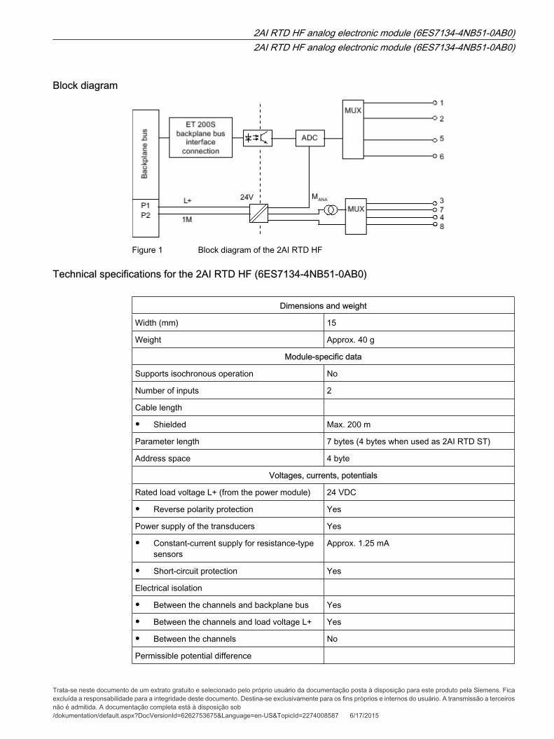
Block diagram
Figure 1 Block diagram of the 2AI RTD HF
Technical specifications for the 2AI RTD HF (6ES7134-4NB51-0AB0)
Dimensions and weight
Width (mm) 15
Weight Approx. 40 g
Module-specific data
Supports isochronous operation No
Number of inputs 2
Cable length
• Shielded Max. 200 m
Parameter length 7 bytes (4 bytes when used as 2AI RTD ST)
Address space 4 byte
Voltages, currents, potentials
Rated load voltage L+ (from the power module) 24 VDC
• Reverse polarity protection Yes
Power supply of the transducers Yes
• Constant-current supply for resistance-typesensors
Approx. 1.25 mA
• Short-circuit protection Yes
Electrical isolation
• Between the channels and backplane bus Yes
• Between the channels and load voltage L+ Yes
• Between the channels No
Permissible potential difference
2AI RTD HF analog electronic module (6ES7134-4NB51-0AB0)2AI RTD HF analog electronic module (6ES7134-4NB51-0AB0)
Trata-se neste documento de um extrato gratuito e selecionado pelo próprio usuário da documentação posta à disposição para este produto pela Siemens. Ficaexcluída a responsabilidade para a integridade deste documento. Destina-se exclusivamente para os fins próprios e internos do usuário. A transmissão a terceirosnão é admitida. A documentação completa está à disposição sob/dokumentation/default.aspx?DocVersionId=6262753675&Language=en-US&TopicId=2274008587 6/17/2015
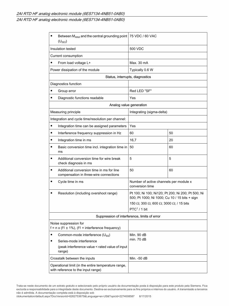
• Between MANA and the central grounding point(UISO)
75 VDC / 60 VAC
Insulation tested 500 VDC
Current consumption
• From load voltage L+ Max. 30 mA
Power dissipation of the module Typically 0.6 W
Status, interrupts, diagnostics
Diagnostics function
• Group error Red LED "SF"
• Diagnostic functions readable Yes
Analog value generation
Measuring principle Integrating (sigma-delta)
Integration and cycle time/resolution per channel:
• Integration time can be assigned parameters Yes
• Interference frequency suppression in Hz 60 50
• Integration time in ms 16,7 20
• Basic conversion time incl. integration time inms
50 60
• Additional conversion time for wire breakcheck diagnosis in ms
5 5
• Additional conversion time in ms for linecompensation in three-wire connections
50 60
• Cycle time in ms Number of active channels per module xconversion time
• Resolution (including overshoot range) Pt 100; Ni 100; Ni120; Pt 200; Ni 200; Pt 500; Ni500; Pt 1000; Ni 1000; Cu 10 / 15 bits + sign150 Ω; 300 Ω; 600 Ω; 3000 Ω; / 15 bitsPTC1 / 1 bit
Suppression of interference, limits of error
Noise suppression for f = n x (f1 ± 1%), (f1 = interference frequency)
• Common-mode interference (USS)
• Series-mode interference(peak interference value < rated value of inputrange)
Min. 90 dB min. 70 dB
Crosstalk between the inputs Min. -50 dB
Operational limit (in the entire temperature range,with reference to the input range)
2AI RTD HF analog electronic module (6ES7134-4NB51-0AB0)2AI RTD HF analog electronic module (6ES7134-4NB51-0AB0)
Trata-se neste documento de um extrato gratuito e selecionado pelo próprio usuário da documentação posta à disposição para este produto pela Siemens. Ficaexcluída a responsabilidade para a integridade deste documento. Destina-se exclusivamente para os fins próprios e internos do usuário. A transmissão a terceirosnão é admitida. A documentação completa está à disposição sob/dokumentation/default.aspx?DocVersionId=6262753675&Language=en-US&TopicId=2274008587 6/17/2015
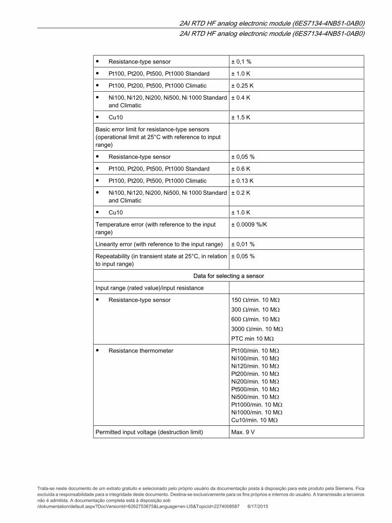
• Resistance-type sensor ± 0,1 %
• Pt100, Pt200, Pt500, Pt1000 Standard ± 1.0 K
• Pt100, Pt200, Pt500, Pt1000 Climatic ± 0.25 K
• Ni100, Ni120, Ni200, Ni500, Ni 1000 Standardand Climatic
± 0.4 K
• Cu10 ± 1.5 K
Basic error limit for resistance-type sensors(operational limit at 25°C with reference to inputrange)
• Resistance-type sensor ± 0,05 %
• Pt100, Pt200, Pt500, Pt1000 Standard ± 0.6 K
• Pt100, Pt200, Pt500, Pt1000 Climatic ± 0.13 K
• Ni100, Ni120, Ni200, Ni500, Ni 1000 Standardand Climatic
± 0.2 K
• Cu10 ± 1.0 K
Temperature error (with reference to the inputrange)
± 0.0009 %/K
Linearity error (with reference to the input range) ± 0,01 %
Repeatability (in transient state at 25°C, in relationto input range)
± 0,05 %
Data for selecting a sensor
Input range (rated value)/input resistance
• Resistance-type sensor 150 Ω/min. 10 MΩ300 Ω/min. 10 MΩ600 Ω/min. 10 MΩ3000 Ω/min. 10 MΩPTC min 10 MΩ
• Resistance thermometer Pt100/min. 10 MΩ Ni100/min. 10 MΩ Ni120/min. 10 MΩ Pt200/min. 10 MΩ Ni200/min. 10 MΩ Pt500/min. 10 MΩ Ni500/min. 10 MΩ Pt1000/min. 10 MΩ Ni1000/min. 10 MΩ Cu10/min. 10 MΩ
Permitted input voltage (destruction limit) Max. 9 V
2AI RTD HF analog electronic module (6ES7134-4NB51-0AB0)2AI RTD HF analog electronic module (6ES7134-4NB51-0AB0)
Trata-se neste documento de um extrato gratuito e selecionado pelo próprio usuário da documentação posta à disposição para este produto pela Siemens. Ficaexcluída a responsabilidade para a integridade deste documento. Destina-se exclusivamente para os fins próprios e internos do usuário. A transmissão a terceirosnão é admitida. A documentação completa está à disposição sob/dokumentation/default.aspx?DocVersionId=6262753675&Language=en-US&TopicId=2274008587 6/17/2015
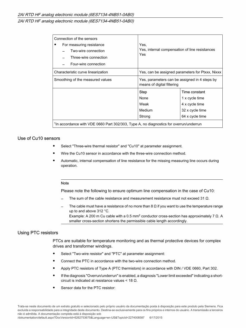
Connection of the sensors
• For measuring resistance― Two-wire connection
― Three-wire connection
― Four-wire connection
Yes, Yes, internal compensation of line resistances Yes
Characteristic curve linearization Yes, can be assigned parameters for Ptxxx, Nixxx
Smoothing of the measured values Yes, parameters can be assigned in 4 steps bymeans of digital filtering
StepNoneWeakMediumStrong
Time constant1 x cycle time4 x cycle time32 x cycle time64 x cycle time
1In accordance with VDE 0660 Part 302/303, Type A, no diagnostics for overrun/underrun
Use of Cu10 sensors
• Select "Three-wire thermal resistor" and "Cu10" at parameter assignment.
• Wire the Cu10 sensor in accordance with the three-wire connection method.
• Automatic, internal compensation of line resistance for the missing measuring line occurs duringoperation.
Note
Please note the following to ensure optimum line compensation in the case of Cu10:
― The sum of the cable resistance and measurement resistance must not exceed 31 Ω.
― The cable must have a resistance of no more than 8 Ω if you want to use the temperature rangeup to and above 312 °C. Example: A 200 m Cu cable with a 0.5 mm2 conductor cross-section has approximately 7 Ω. Asmaller cross-section shortens the permissible cable length accordingly.
Using PTC resistorsPTCs are suitable for temperature monitoring and as thermal protective devices for complexdrives and transformer windings.
• Select "Two-wire resistor" and "PTC" at parameter assignment:
• Connect the PTC in accordance with the two-wire connection method.
• Apply PTC resistors of Type A (PTC thermistors) in accordance with DIN / VDE 0660, Part 302.
• If the diagnosis "Overrun/underrun" is enabled, a diagnosis "Lower limit exceeded" indicating a short-circuit is indicated at resistance values < 18 Ω.
• Sensor data for the PTC resistor:
2AI RTD HF analog electronic module (6ES7134-4NB51-0AB0)2AI RTD HF analog electronic module (6ES7134-4NB51-0AB0)
Trata-se neste documento de um extrato gratuito e selecionado pelo próprio usuário da documentação posta à disposição para este produto pela Siemens. Ficaexcluída a responsabilidade para a integridade deste documento. Destina-se exclusivamente para os fins próprios e internos do usuário. A transmissão a terceirosnão é admitida. A documentação completa está à disposição sob/dokumentation/default.aspx?DocVersionId=6262753675&Language=en-US&TopicId=2274008587 6/17/2015
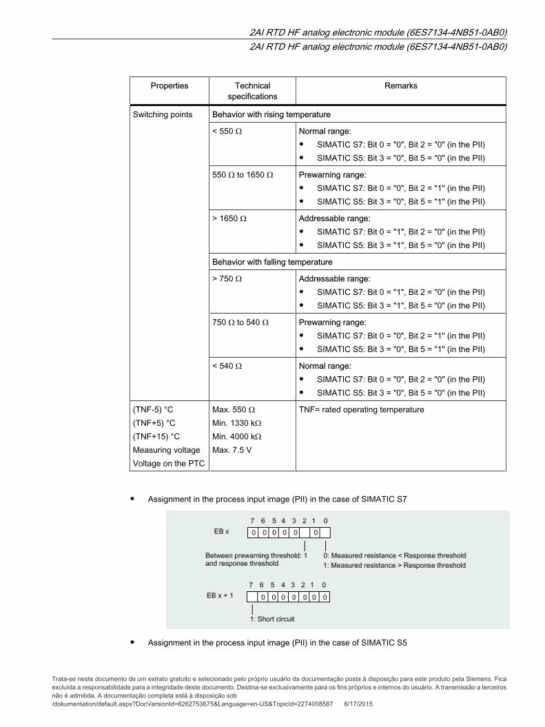
Properties Technicalspecifications
Remarks
Switching points Behavior with rising temperature
< 550 Ω Normal range:
• SIMATIC S7: Bit 0 = "0", Bit 2 = "0" (in the PII)
• SIMATIC S5: Bit 3 = "0", Bit 5 = "0" (in the PII)
550 Ω to 1650 Ω Prewarning range:
• SIMATIC S7: Bit 0 = "0", Bit 2 = "1" (in the PII)
• SIMATIC S5: Bit 3 = "0", Bit 5 = "1" (in the PII)
> 1650 Ω Addressable range:
• SIMATIC S7: Bit 0 = "1", Bit 2 = "0" (in the PII)
• SIMATIC S5: Bit 3 = "1", Bit 5 = "0" (in the PII)
Behavior with falling temperature
> 750 Ω Addressable range:
• SIMATIC S7: Bit 0 = "1", Bit 2 = "0" (in the PII)
• SIMATIC S5: Bit 3 = "1", Bit 5 = "0" (in the PII)
750 Ω to 540 Ω Prewarning range:
• SIMATIC S7: Bit 0 = "0", Bit 2 = "1" (in the PII)
• SIMATIC S5: Bit 3 = "0", Bit 5 = "1" (in the PII)
< 540 Ω Normal range:
• SIMATIC S7: Bit 0 = "0", Bit 2 = "0" (in the PII)
• SIMATIC S5: Bit 3 = "0", Bit 5 = "0" (in the PII)
(TNF-5) °C(TNF+5) °C(TNF+15) °CMeasuring voltageVoltage on the PTC
Max. 550 ΩMin. 1330 kΩMin. 4000 kΩMax. 7.5 V
TNF= rated operating temperature
• Assignment in the process input image (PII) in the case of SIMATIC S7
• Assignment in the process input image (PII) in the case of SIMATIC S5
2AI RTD HF analog electronic module (6ES7134-4NB51-0AB0)2AI RTD HF analog electronic module (6ES7134-4NB51-0AB0)
Trata-se neste documento de um extrato gratuito e selecionado pelo próprio usuário da documentação posta à disposição para este produto pela Siemens. Ficaexcluída a responsabilidade para a integridade deste documento. Destina-se exclusivamente para os fins próprios e internos do usuário. A transmissão a terceirosnão é admitida. A documentação completa está à disposição sob/dokumentation/default.aspx?DocVersionId=6262753675&Language=en-US&TopicId=2274008587 6/17/2015
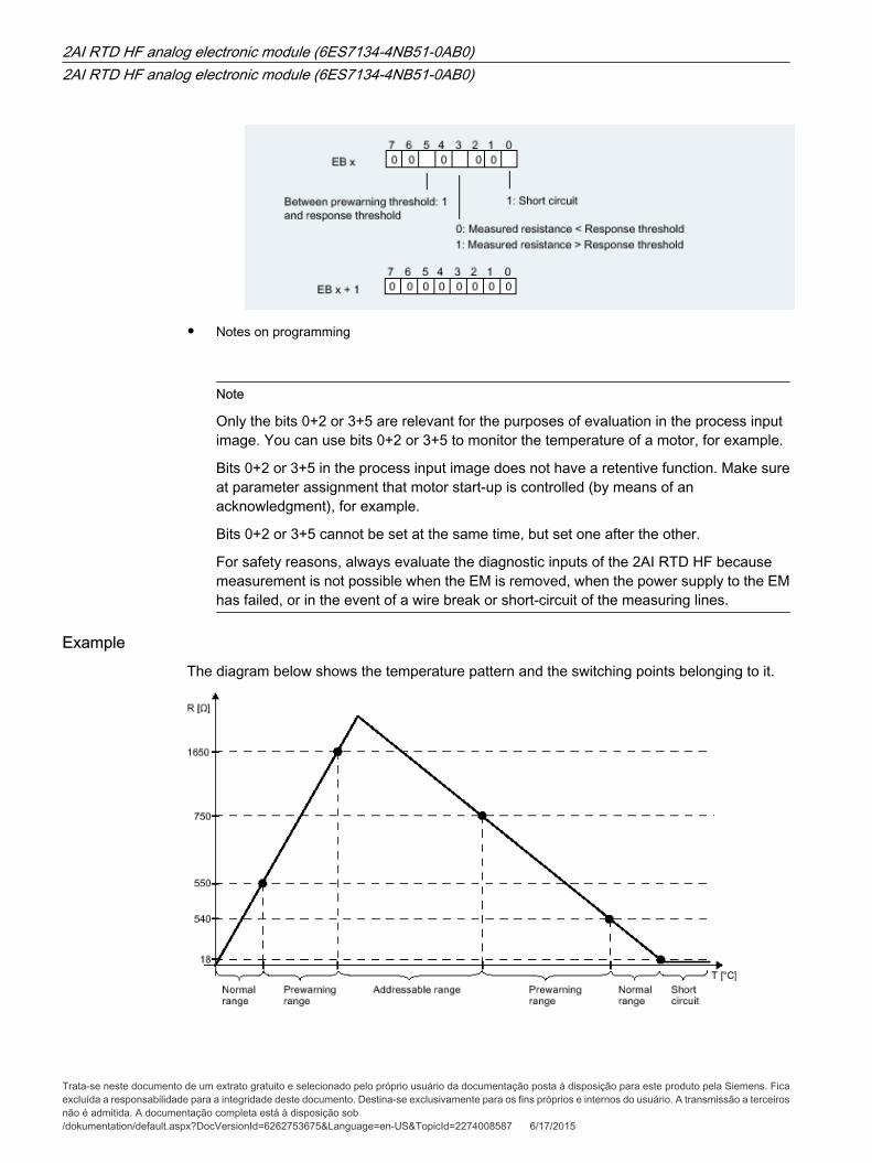
• Notes on programming
Note
Only the bits 0+2 or 3+5 are relevant for the purposes of evaluation in the process inputimage. You can use bits 0+2 or 3+5 to monitor the temperature of a motor, for example.
Bits 0+2 or 3+5 in the process input image does not have a retentive function. Make sureat parameter assignment that motor start-up is controlled (by means of anacknowledgment), for example.
Bits 0+2 or 3+5 cannot be set at the same time, but set one after the other.
For safety reasons, always evaluate the diagnostic inputs of the 2AI RTD HF becausemeasurement is not possible when the EM is removed, when the power supply to the EMhas failed, or in the event of a wire break or short-circuit of the measuring lines.
ExampleThe diagram below shows the temperature pattern and the switching points belonging to it.
2AI RTD HF analog electronic module (6ES7134-4NB51-0AB0)2AI RTD HF analog electronic module (6ES7134-4NB51-0AB0)
Trata-se neste documento de um extrato gratuito e selecionado pelo próprio usuário da documentação posta à disposição para este produto pela Siemens. Ficaexcluída a responsabilidade para a integridade deste documento. Destina-se exclusivamente para os fins próprios e internos do usuário. A transmissão a terceirosnão é admitida. A documentação completa está à disposição sob/dokumentation/default.aspx?DocVersionId=6262753675&Language=en-US&TopicId=2274008587 6/17/2015