18.01.06J. Jones (Imperial College London), Alt. GCT Mini-Meeting GCT Source Card.
11
18.01.06 J. Jones (Imperial College London), Alt. GCT Mini-M eeting GCT Source Card
-
Upload
janae-rushworth -
Category
Documents
-
view
232 -
download
0
Transcript of 18.01.06J. Jones (Imperial College London), Alt. GCT Mini-Meeting GCT Source Card.
18.01.06 J. Jones (Imperial College London), Alt. GCT Mini-Meeting
GCT Source Card
J. Jones (Imperial College London), Alt. GCT Mini-Meeting 218.01.06
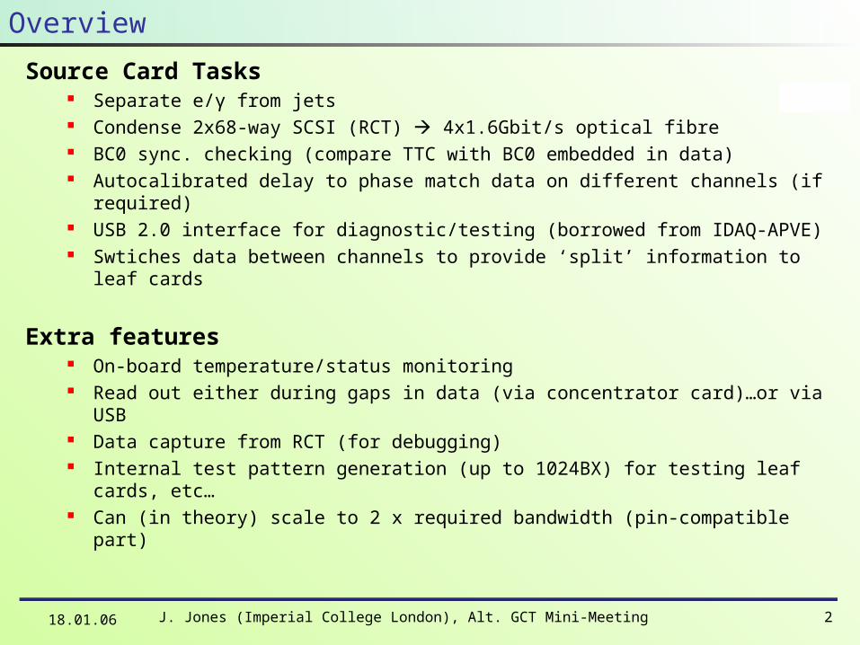
Overview
Source Card Tasks Separate e/γ from jets Condense 2x68-way SCSI (RCT) 4x1.6Gbit/s optical fibre BC0 sync. checking (compare TTC with BC0 embedded in data) Autocalibrated delay to phase match data on different channels (if required) USB 2.0 interface for diagnostic/testing (borrowed from IDAQ-APVE) Swtiches data between channels to provide ‘split’ information to leaf cards
Extra features On-board temperature/status monitoring Read out either during gaps in data (via concentrator card)…or via USB Data capture from RCT (for debugging) Internal test pattern generation (up to 1024BX) for testing leaf cards, etc… Can (in theory) scale to 2 x required bandwidth (pin-compatible part)
J. Jones (Imperial College London), Alt. GCT Mini-Meeting 318.01.06
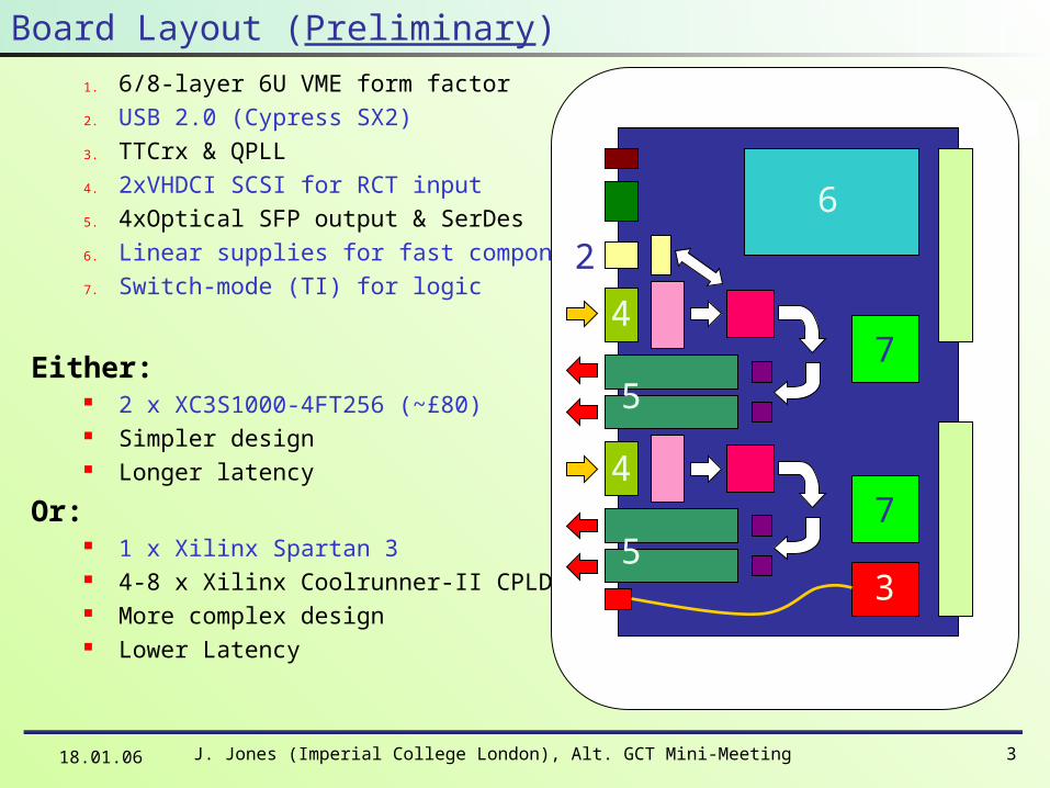
1. 6/8-layer 6U VME form factor
2. USB 2.0 (Cypress SX2)
3. TTCrx & QPLL
4. 2xVHDCI SCSI for RCT input
5. 4xOptical SFP output & SerDes
6. Linear supplies for fast components
7. Switch-mode (TI) for logic
Either: 2 x XC3S1000-4FT256 (~£80) Simpler design Longer latency
Or: 1 x Xilinx Spartan 3 4-8 x Xilinx Coolrunner-II CPLD More complex design Lower Latency
Board Layout (Preliminary)
2
3
4
4
5
5
6
7
7
J. Jones (Imperial College London), Alt. GCT Mini-Meeting 418.01.06
Functional Issues (To Be Discussed)
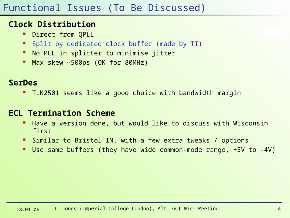
Clock Distribution Direct from QPLL Split by dedicated clock buffer (made by TI) No PLL in splitter to minimise jitter Max skew ~500ps (OK for 80MHz)
SerDes TLK2501 seems like a good choice with bandwidth margin
ECL Termination Scheme Have a version done, but would like to discuss with Wisconsin first Similar to Bristol IM, with a few extra tweaks / options Use same buffers (they have wide common-mode range, +5V to -4V)
J. Jones (Imperial College London), Alt. GCT Mini-Meeting 518.01.06
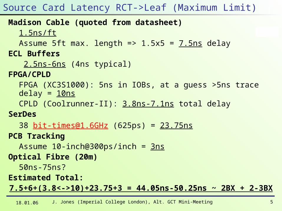
Source Card Latency RCT->Leaf (Maximum Limit)
Madison Cable (quoted from datasheet)1.5ns/ftAssume 5ft max. length => 1.5x5 = 7.5ns delay
ECL Buffers 2.5ns-6ns (4ns typical)
FPGA/CPLDFPGA (XC3S1000): 5ns in IOBs, at a guess >5ns trace delay = 10nsCPLD (Coolrunner-II): 3.8ns-7.1ns total delay
SerDes38 [email protected] (625ps) = 23.75ns
PCB TrackingAssume 10-inch@300ps/inch = 3ns
Optical Fibre (20m)50ns-75ns?
Estimated Total:7.5+6+(3.8<->10)+23.75+3 = 44.05ns-50.25ns ~ 2BX + 2-3BX
J. Jones (Imperial College London), Alt. GCT Mini-Meeting 618.01.06
Source Card Skew (Maximum Limit)
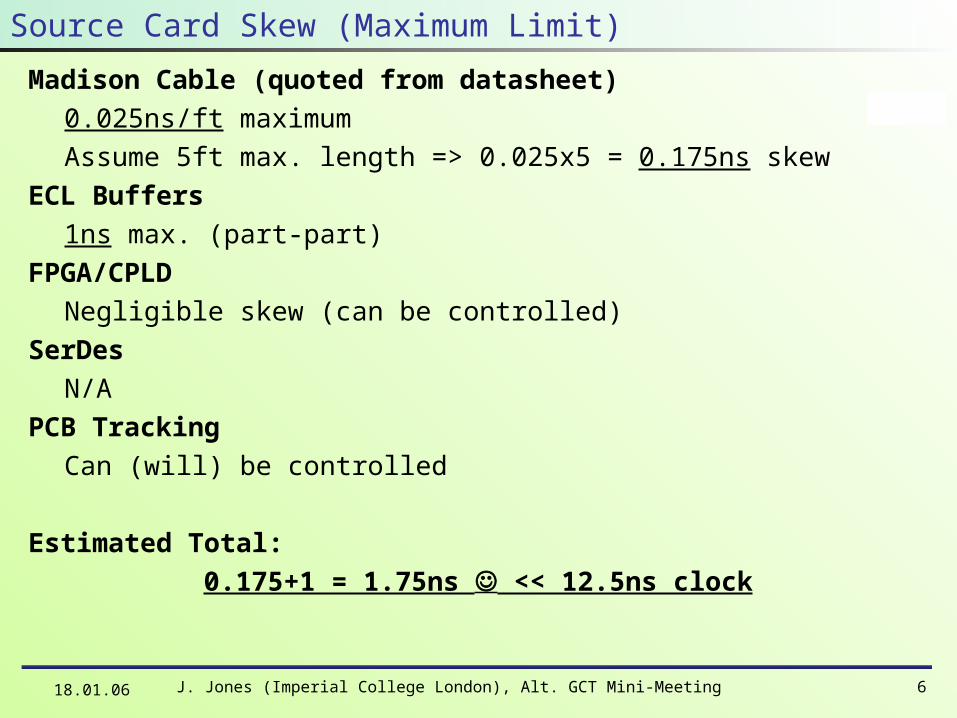
Madison Cable (quoted from datasheet)
0.025ns/ft maximum
Assume 5ft max. length => 0.025x5 = 0.175ns skew
ECL Buffers
1ns max. (part-part)
FPGA/CPLD
Negligible skew (can be controlled)
SerDes
N/A
PCB Tracking
Can (will) be controlled
Estimated Total:
0.175+1 = 1.75ns << 12.5ns clock
J. Jones (Imperial College London), Alt. GCT Mini-Meeting 718.01.06
Board Testing Plan
Power-Up Testing of Power Supplies
Modular design of power system makes this simple
Power Plane Short Testing
Manual / automatic process, takes ~5 mins
JTAG Testing
Script can be developed at Imperial (done for previous boards)
Script can be sent to assembly company for automated checking
Functionality Testing
Full testing can only be achieved by loading the FPGAs/CPLDs
Aim to generate a test firmware
Loop back TX/RX on optical links, ECL drive buffers using a test card
Source card can be fully ‘internally’ tested
J. Jones (Imperial College London), Alt. GCT Mini-Meeting 818.01.06
Functionality Testing (Detail)
Software
C++ based via USB 2.0 link
Tested successfully in current project (IDAQ) @ 28MB/s
in two days continuous operation (Beam Test)
Firmware
USB firmware complete
Functionality-testing firmware will be developed in parallel with layout and finished after submission of design to manufacture
Drive optical links with psuedo-random, A-5, ramp, pseudo-RCT
Qualify link BER to <10-12 at 2Gbit/s before use with leaf cards
This will take ~10 mins set-up & test per card
60 cards = 600 mins (10 hours) day job (apart from failures!)

J. Jones (Imperial College London), Alt. GCT Mini-Meeting 918.01.06
Risk Assessment
Software
Basic test framework already complete for another project
Final system may well be ‘stateless’, otherwise can implement XDAQ layer for USB interface, configuration can be sent via TTC
Firmware
USB, I2C complete
Major component left is calibration functionality
Wishbone bus interfaces already developed for another project
A. Rose & J. Jones will be sufficient to develop this
Critical components will be simulated before board submission
Hardware
MGT links are highest risk, but we have application notes / reference designs to assist in layout and ensure no major mistakes
Fast / difficult components will be spice simulated before manufacture
Deliberate ‘overkill’ in programmable logic usage (1M Spartan 3 is big)
J. Jones (Imperial College London), Alt. GCT Mini-Meeting 1018.01.06
Build Plan & Price (Guess)
Schematic
J. Jones (IC)
Layout
S. Greenwood (IC) – Power supplies currently be laid out
Manufacture (awaiting quote from Cemgraft)
Have checked, they’re not very busy a.t.m.
Cemgraft (assembly/parts)
ExceptionPCB (PCB manufacture)
Good experience with complex high-speed boards in the past
18 RCT crates x 6 cables / 2 => 54 cards
Should be < £1000 / card => ~£60,000 for 60 required (with spares)
J. Jones (Imperial College London), Alt. GCT Mini-Meeting 1118.01.06
Schedule
Schematic (1-2 months)
Currently 60-70% complete
Aim to finalise by end of February
Layout (2 months)
End of February, possibly mid-March
Parts (2 months, may be 3 if delayed)
Critical parts ordered by end of January (avoiding specialised ones)
Aim to get prototype parts by submission date
Firmware (2 months)
J. Jones & A. Rose
USB software & firmware already written
Major component left is clocking / calibration firmware for data path
March/April is contingency (leaf card is probably not available until the end of April?)