1 Electromagnetic waves Hecht, Chapter 2 Wednesday October 23, 2002.
32
1 Electromagnetic waves Hecht, Chapter 2 Wednesday October 23, 2002
-
Upload
eugenia-hunter -
Category
Documents
-
view
231 -
download
2
Transcript of 1 Electromagnetic waves Hecht, Chapter 2 Wednesday October 23, 2002.
1
Electromagnetic waves
Hecht, Chapter 2
Wednesday October 23, 2002
2
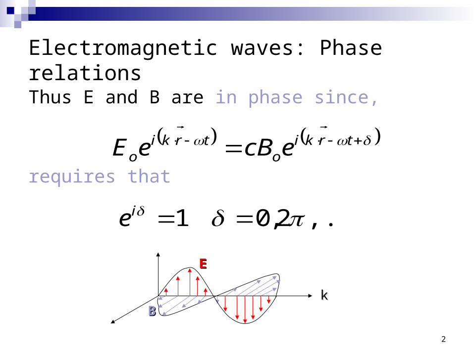
Electromagnetic waves: Phase relations
Thus E and B are in phase since,
requires that
trkio
trkio ecBeE
,...2,01 ie
EE
BBkk
3
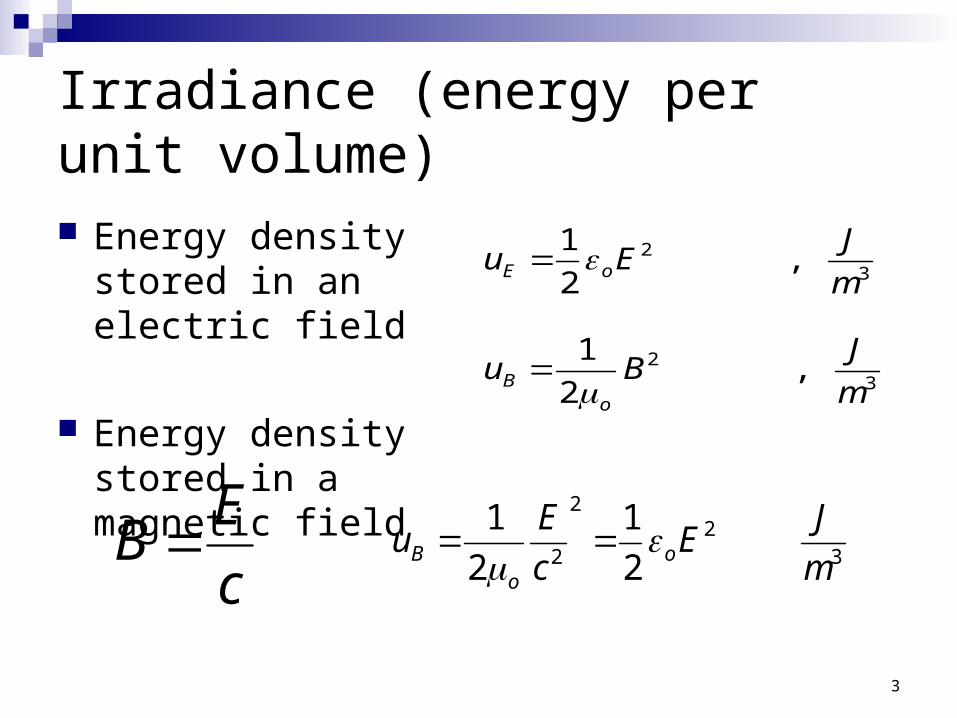
Irradiance (energy per unit volume)
Energy density stored in an electric field
Energy density stored in a magnetic field
32 ,
2
1
m
JEu oE
32 ,
2
1
m
JBu
oB
c
EB 3
22
2 2
1
2
1
m
JE
c
Eu o
oB
4
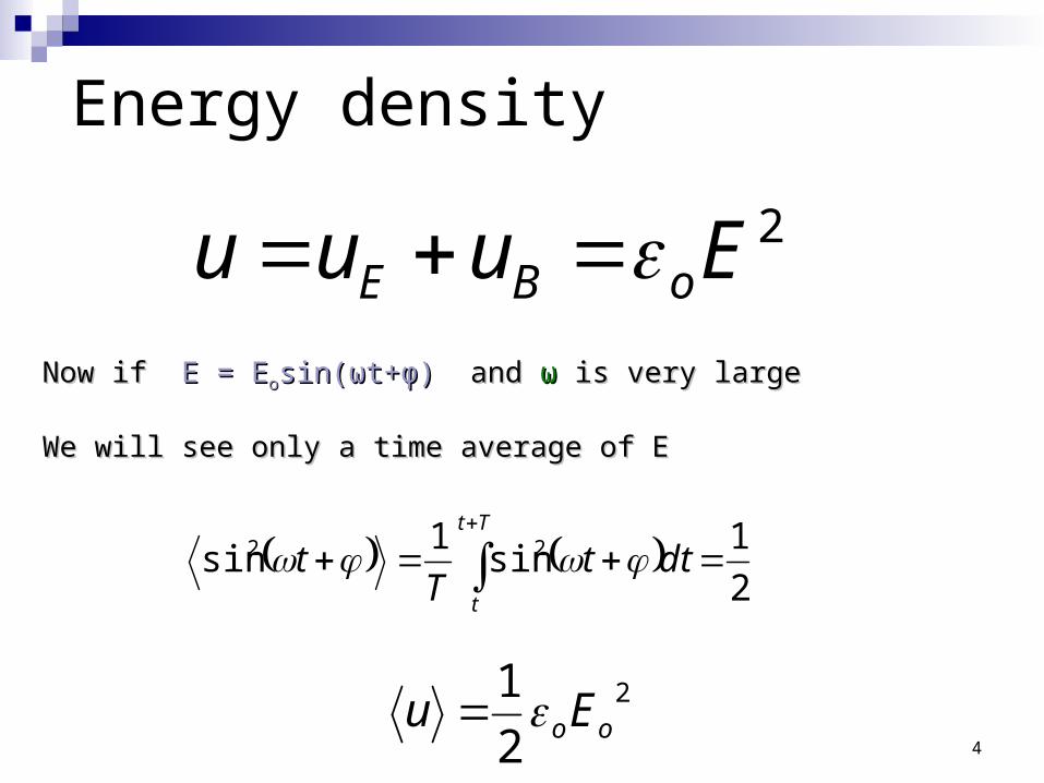
Energy density
2Euuu oBE Now if Now if E = EE = Eoosin(sin(ωωt+t+φφ)) and and ωω is very large is very large
We will see only a time average of EWe will see only a time average of E
2
1sin
1sin 22
dttT
tTt
t
2
2
1ooEu
5
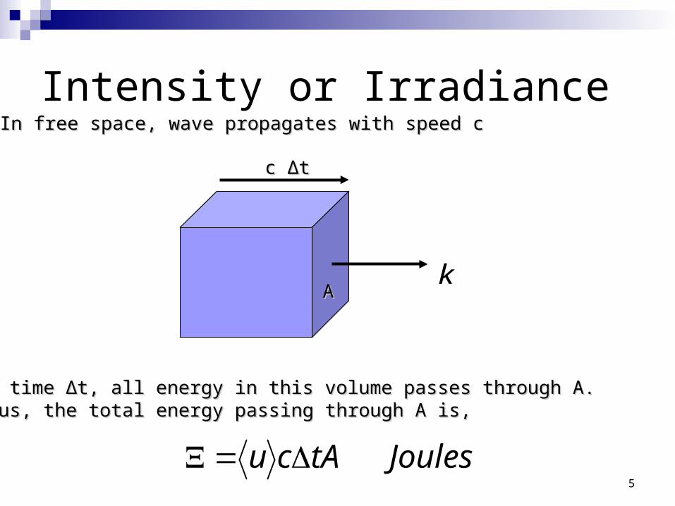
Intensity or Irradiance
k
In free space, wave propagates with speed cIn free space, wave propagates with speed c
c c ΔΔtt
AA
In time In time ΔΔt, all energy in this volume passes through A.t, all energy in this volume passes through A.Thus, the total energy passing through A is,Thus, the total energy passing through A is,
JoulestAcu
6
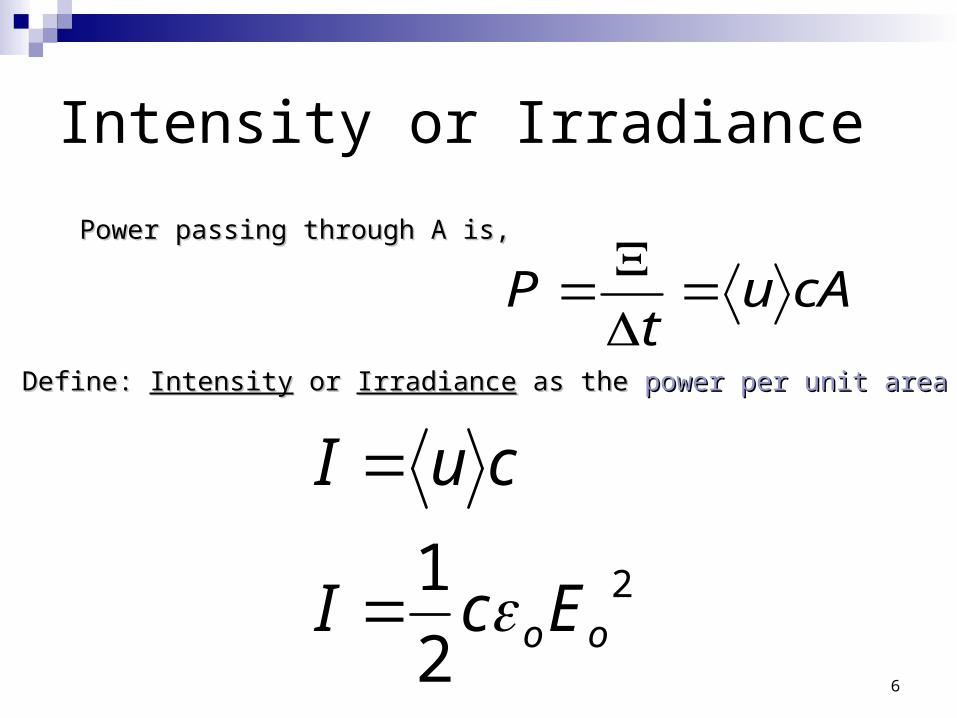
Intensity or Irradiance
cAut
P
Power passing through A is,Power passing through A is,
Define: Define: IntensityIntensity or or IrradianceIrradiance as the as the power per unit areapower per unit area
2
2
1ooEcI
cuI
7
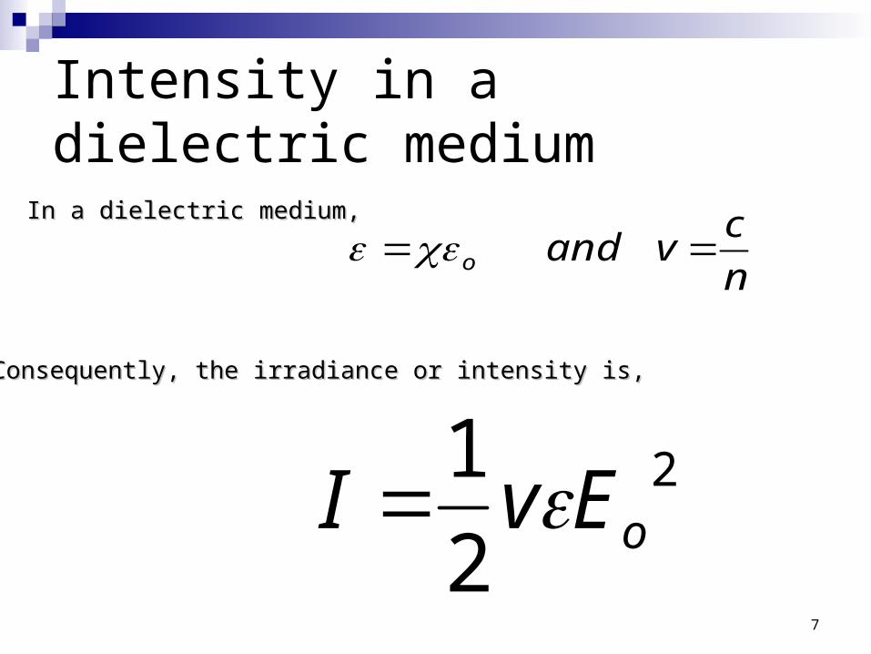
Intensity in a dielectric medium
n
cvando
In a dielectric medium,In a dielectric medium,
Consequently, the irradiance or intensity is,Consequently, the irradiance or intensity is,
2
2
1oEvI
8
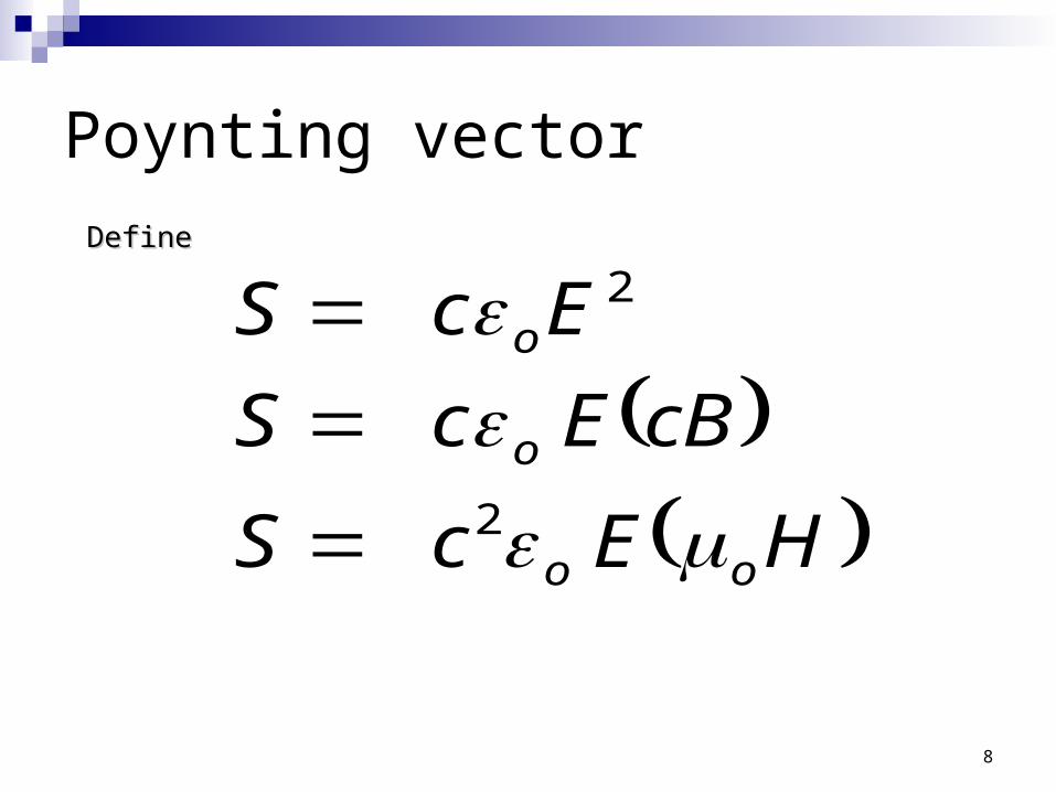
Poynting vector
DefineDefine
HEcS
cBEcS
EcS
oo
o
o
2
2
9
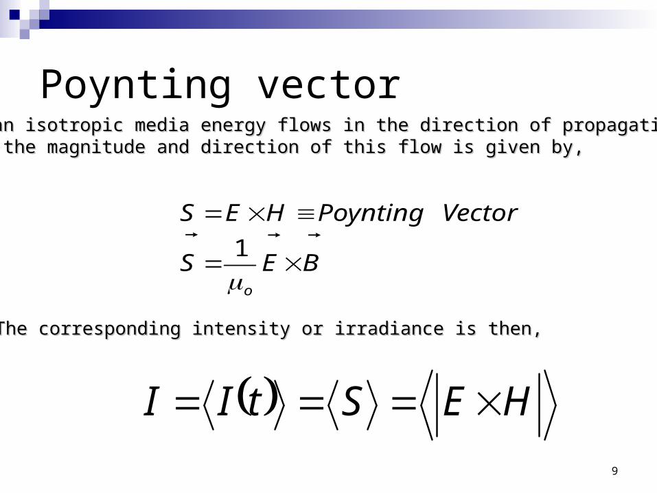
Poynting vector
BES
VectorPoyntingHES
o
1
For an isotropic media energy flows in the direction of propagation, soFor an isotropic media energy flows in the direction of propagation, soboth the magnitude and direction of this flow is given by,both the magnitude and direction of this flow is given by,
HEStII
The corresponding intensity or irradiance is then,The corresponding intensity or irradiance is then,
10
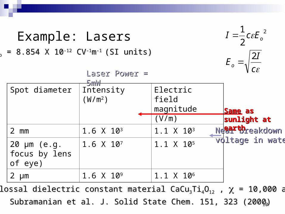
Example: Lasers
Spot diameter Intensity (W/m2) Electric field magnitude (V/m)
2 mm 1.6 X 10³ 1.1 X 10³
20 µm (e.g. focus by lens of eye)
1.6 X 10⁷ 1.1 X 10⁵
2 µm 1.6 X 10⁹ 1.1 X 10⁶
Laser Power = 5mWLaser Power = 5mW
nb. Colossal dielectric constant material CaCunb. Colossal dielectric constant material CaCu33TiTi44OO1212 , , = 10,000 at 300K = 10,000 at 300K
Subramanian et al. J. Solid State Chem. 151, 323 (2000)Subramanian et al. J. Solid State Chem. 151, 323 (2000)
Near breakdownNear breakdownvoltage in watervoltage in water
c
IE
EcI
o
o
2
2
1 2
Same as Same as sunlight at earthsunlight at earth
oo = 8.854 X 10 = 8.854 X 10⁻¹²-12 CV CV-1-1mm-1 -1 (SI units)(SI units)
11
Reflection, Transmission and Interference of EM waves
12
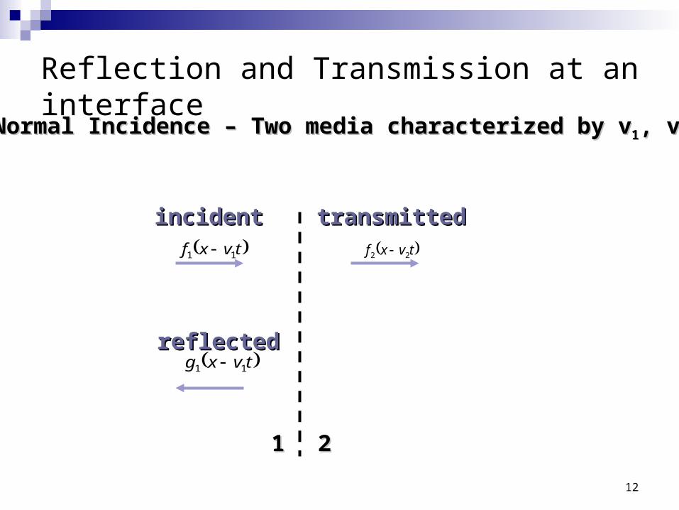
Reflection and Transmission at an interface
tvxf 11 tvxf 22
tvxg 11
11 22
Normal Incidence – Two media characterized by vNormal Incidence – Two media characterized by v11, v, v22
incidentincident transmittedtransmitted
reflectedreflected
13
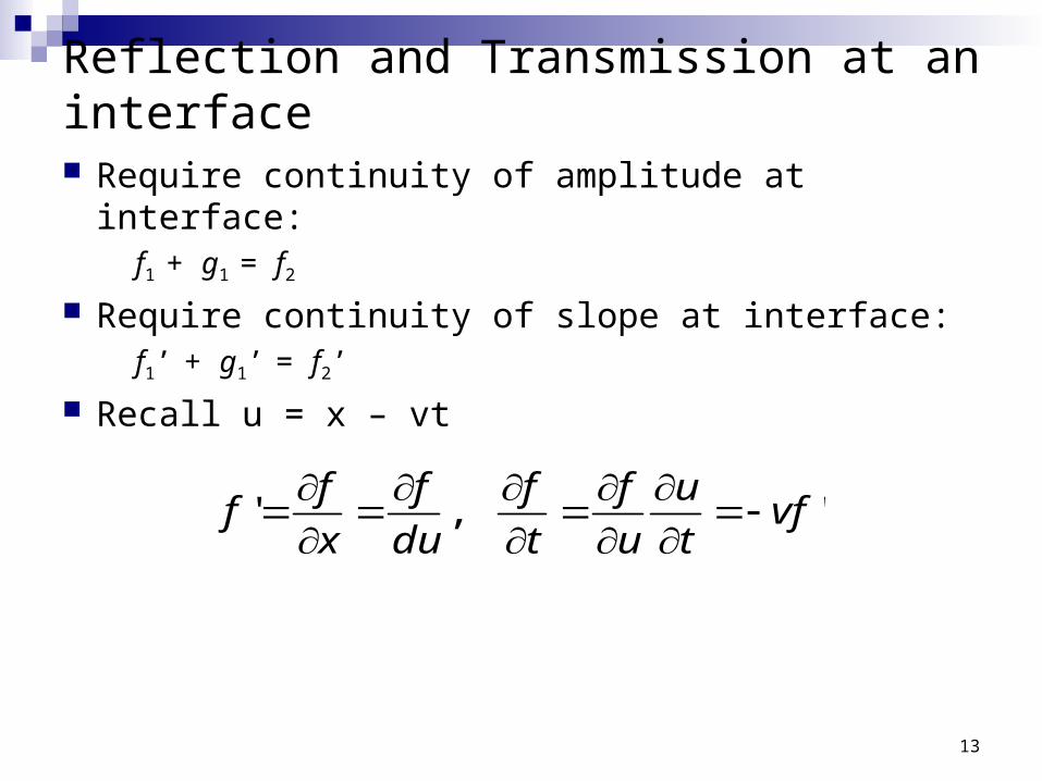
Reflection and Transmission at an interface
Require continuity of amplitude at interface:f1 + g1 = f2
Require continuity of slope at interface:f1’ + g1’ = f2’
Recall u = x – vt
',' vft
u
u
f
t
f
du
f
x
ff
14
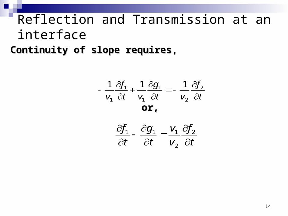
Reflection and Transmission at an interface
t
f
vt
g
vt
f
v
2
2
1
1
1
1
111
Continuity of slope requires,Continuity of slope requires,
t
f
v
v
t
g
t
f
2
2
111
or,or,
15
Reflection and Transmission at an interface
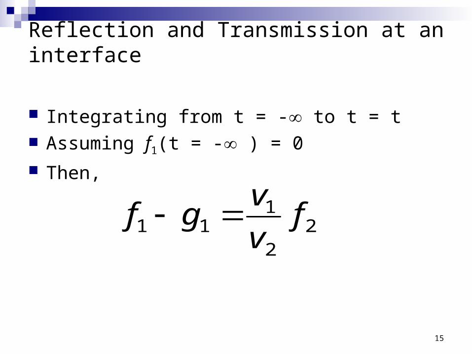
Integrating from t = - to t = t Assuming f1(t = - ) = 0 Then,
22
111 fv
vgf
16
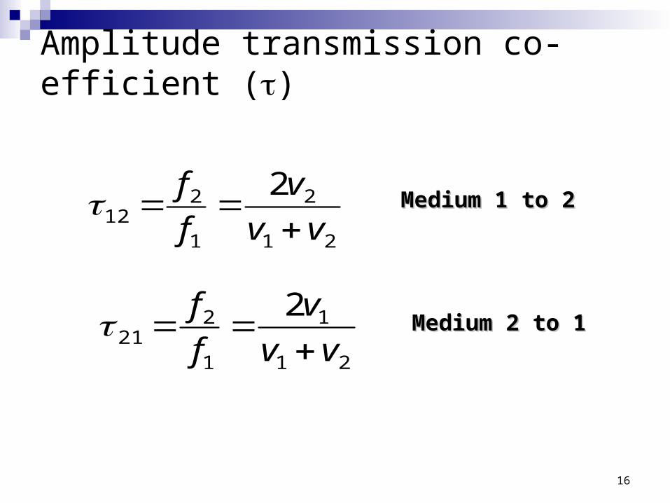
Amplitude transmission co-efficient ()
21
2
1
212
2
vv
v
f
f
Medium 1 to 2Medium 1 to 2
21
1
1
221
2
vv
v
f
f
Medium 2 to 1Medium 2 to 1
17
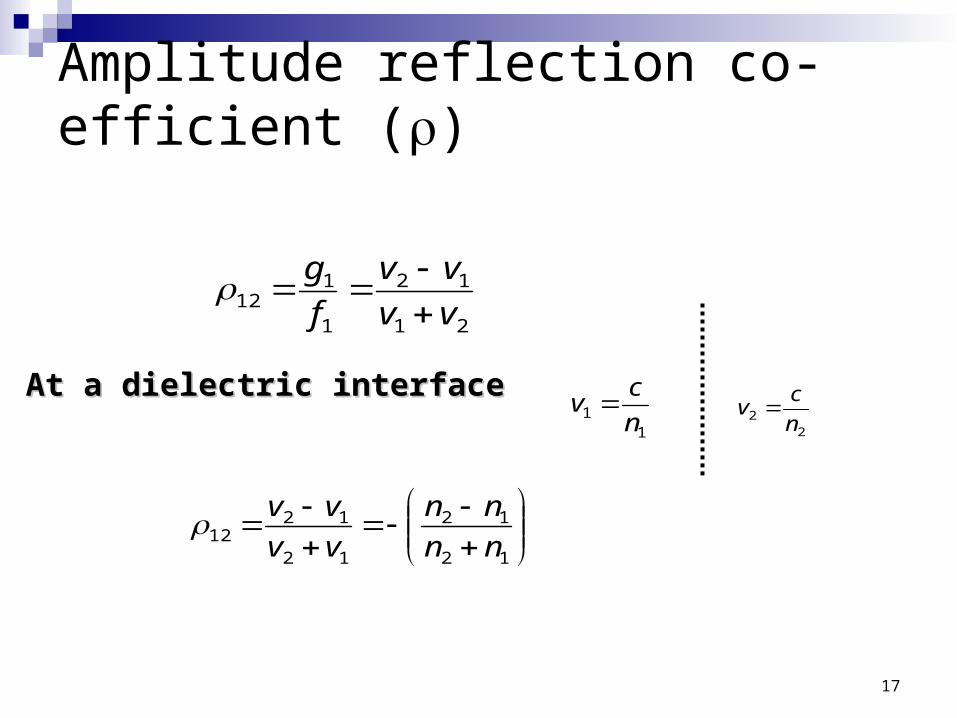
Amplitude reflection co-efficient ()
21
12
1
112 vv
vv
f
g
12
12
12
1212 nn
nn
vv
vv
11 n
cv At a dielectric interfaceAt a dielectric interface
22 n
cv
18
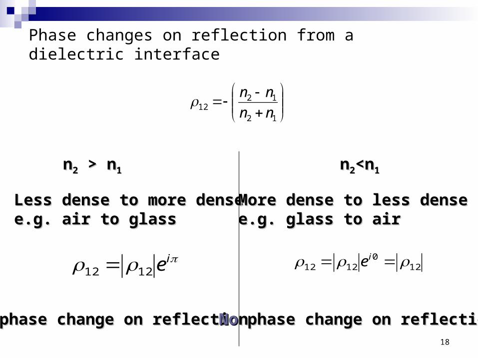
Phase changes on reflection from a dielectric interface
12
1212 nn
nn
120
1212 ie
nn22 > n > n11 nn22<n<n11
Less dense to more denseLess dense to more densee.g. air to glasse.g. air to glass
More dense to less denseMore dense to less densee.g. glass to aire.g. glass to air
ie1212
phase change on reflectionphase change on reflection NoNo phase change on reflection phase change on reflection
19
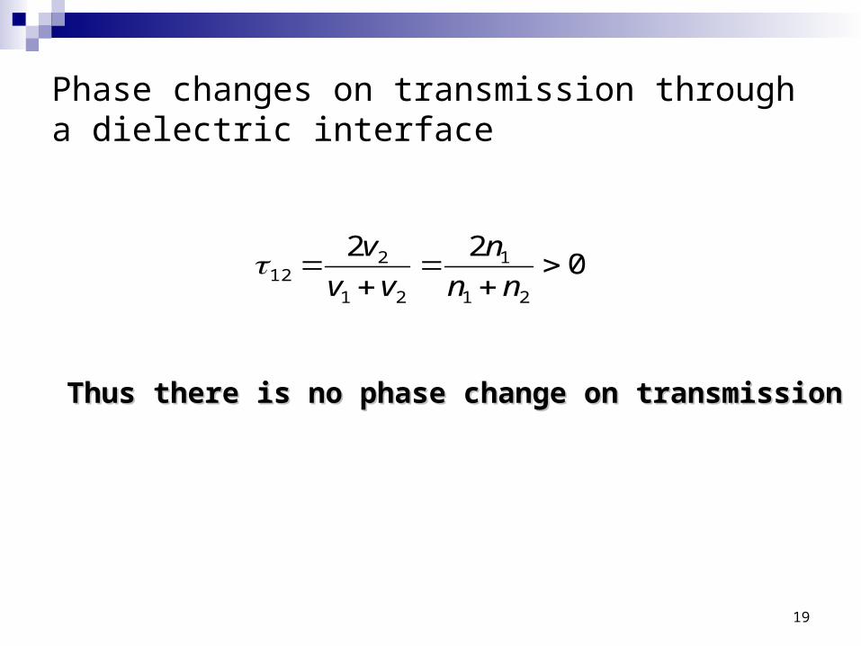
Phase changes on transmission through a dielectric interface
022
21
1
21
212
nn
n
vv
v
Thus there is no phase change on transmissionThus there is no phase change on transmission
20
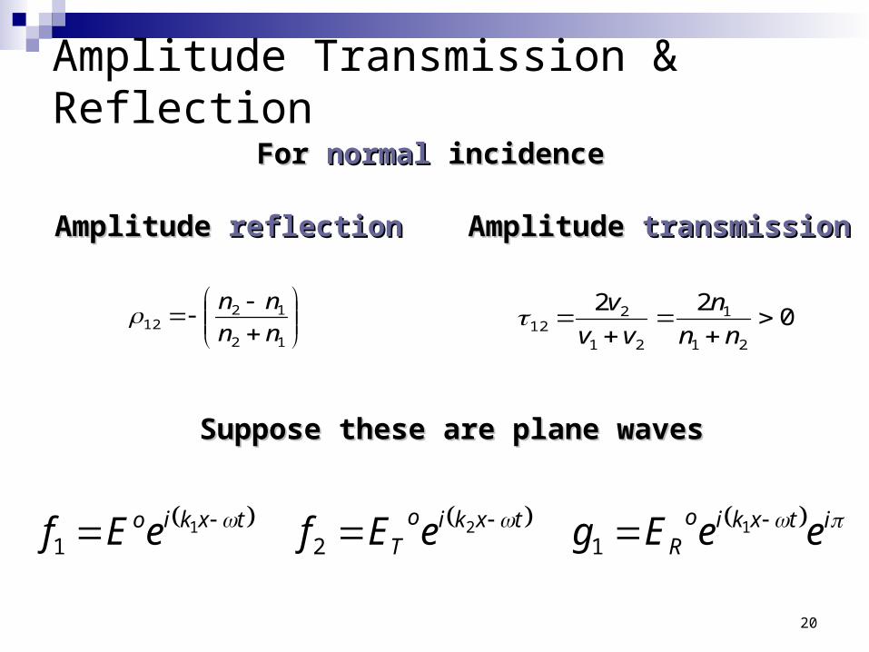
Amplitude Transmission & Reflection
022
21
1
21
212
nn
n
vv
v
12
1212 nn
nn
For For normalnormal incidence incidence
Amplitude Amplitude reflectionreflection Amplitude Amplitude transmissiontransmission
Suppose these are plane wavesSuppose these are plane waves
itxkioR
txkioT
txkio eeEgeEfeEf 121121
21
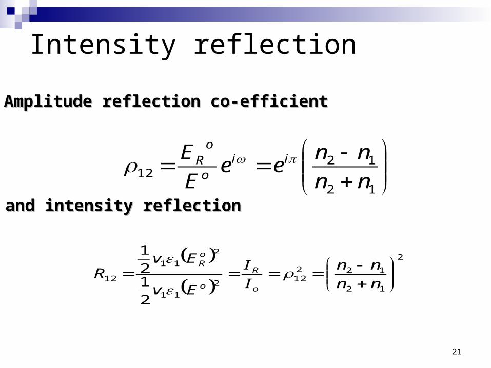
Intensity reflection
12
1212 nn
nnee
E
E iio
oR
Amplitude reflection co-efficientAmplitude reflection co-efficient
and intensity reflectionand intensity reflection
2
12
12212
2
11
2
11
12
2121
nn
nn
I
I
Ev
EvR
o
R
o
oR
22
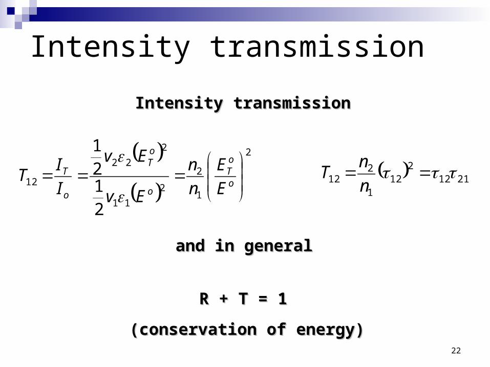
Intensity transmission
2
1
2
2
11
2
22
12
2121
o
oT
o
oT
o
T
E
E
n
n
Ev
Ev
I
IT
Intensity transmissionIntensity transmission
and in generaland in general
21122
121
212
n
nT
R + T = 1R + T = 1
(conservation of energy)(conservation of energy)
23
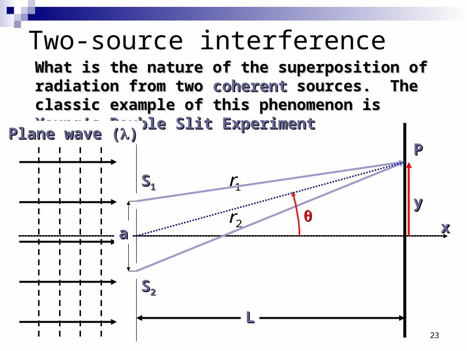
Two-source interference
1r
What is the nature of the superposition of radiation What is the nature of the superposition of radiation from two from two coherentcoherent sources. The classic example of sources. The classic example of this phenomenon is this phenomenon is Young’s Double Slit ExperimentYoung’s Double Slit Experiment
aa
SS11
SS22
xx
LL
Plane wave (Plane wave ())
2r
PP
yy
24
Young’s Double slit experiment
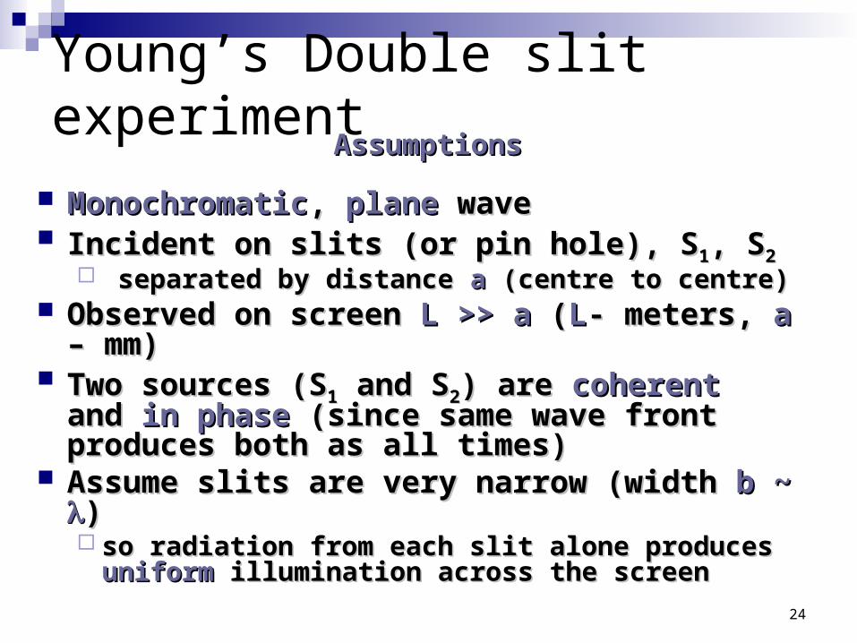
MonochromaticMonochromatic, , planeplane wave wave Incident on slits (or pin hole), SIncident on slits (or pin hole), S11, S, S22
separated by distance separated by distance aa (centre to centre) (centre to centre) Observed on screen Observed on screen L >> a L >> a ((LL- meters, - meters, aa – –
mm)mm) Two sources (STwo sources (S11 and S and S22) are ) are coherentcoherent and and in in
phasephase (since same wave front produces both (since same wave front produces both as all times)as all times)
Assume slits are very narrow (width Assume slits are very narrow (width b ~ b ~ ) ) so radiation from each slit alone produces so radiation from each slit alone produces
uniformuniform illumination across the screen illumination across the screen
AssumptionsAssumptions
25
Young’s double slit experiment
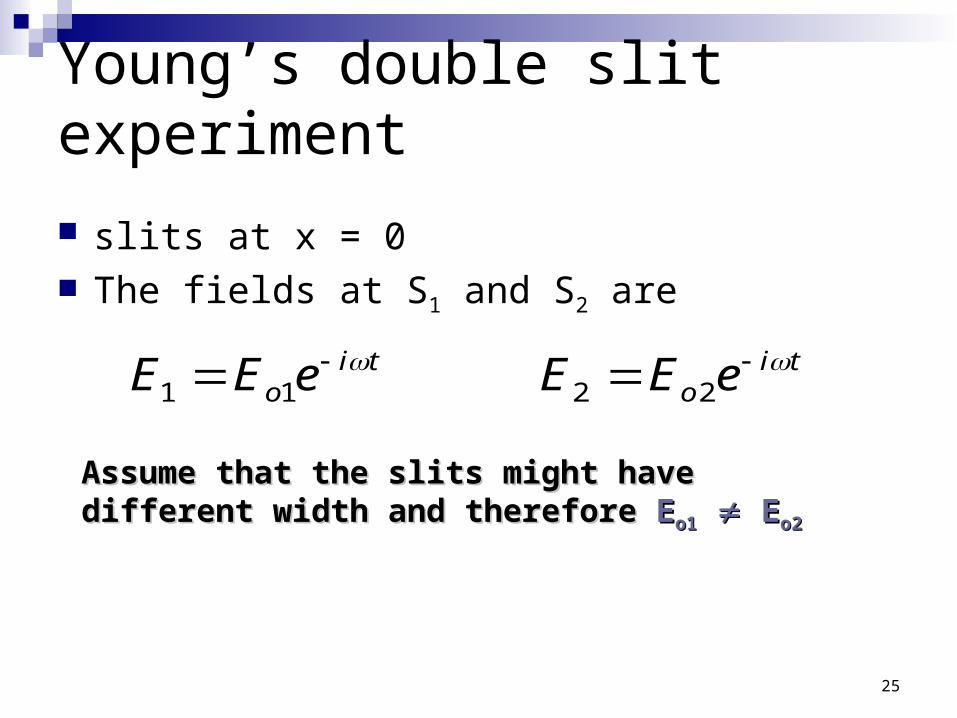
slits at x = 0 The fields at S1 and S2 are
Assume that the slits might have different width Assume that the slits might have different width and therefore and therefore EEo1o1 E Eo2o2
tio
tio eEEeEE 2211
26
Young’s double slit experiment
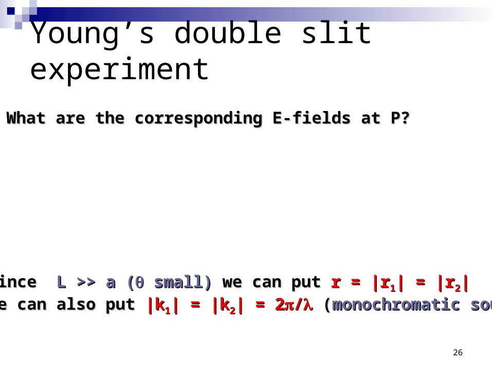
What are the corresponding E-fields at P?What are the corresponding E-fields at P?
trkioP
trkioP e
r
EEe
r
EE 21
2
22
1
11
Since Since L >> a (L >> a ( small) small) we can put we can put r = |rr = |r11| = |r| = |r22||
We can also put We can also put |k|k11| = |k| = |k22| = 2| = 2// ( (monochromatic sourcemonochromatic source))
27
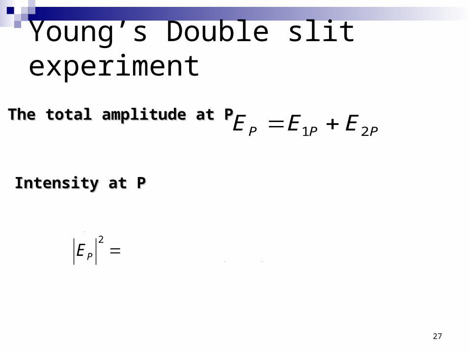
Young’s Double slit experiment
PPP EEE 21
22
2
1oPEvEvI PP
The total amplitude at PThe total amplitude at P
Intensity at PIntensity at P
**22
**21
*2
122121
21
PPPPPP
PP
P
EEEEEE
EEEE
EEE
PP
PP
28
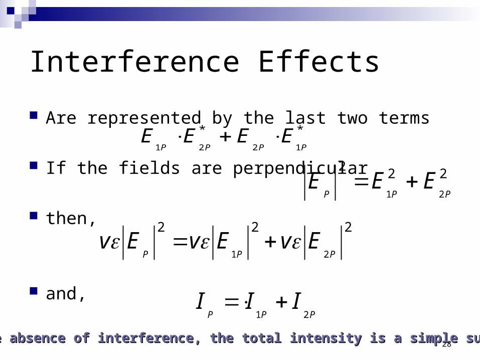
Interference Effects
Are represented by the last two terms
If the fields are perpendicular
then,
and,
**
1221 PPPPEEEE
222
21 PPPEEE
PPPIII
21
222
21 PPPEvEvEv
In the absence of interference, the total intensity is a simple sumIn the absence of interference, the total intensity is a simple sum
29
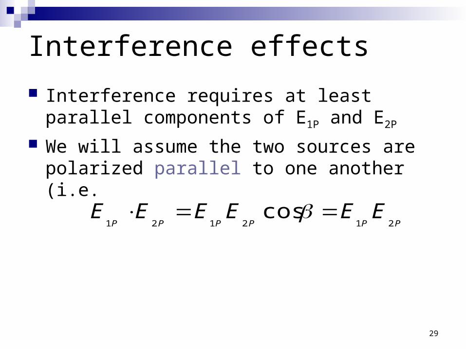
Interference effects
Interference requires at least parallel components of E1P and E2P
We will assume the two sources are polarized parallel to one another (i.e.
PPPPPPEEEEEE
212121cos
30
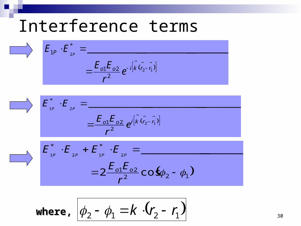
Interference terms
12
2
221
*1 ____________________________
rrkioo
P
er
EE
EEP
12
21
221
* ____________________________
rrkioo er
EE
EEPP
12221
**
cos2
_________________2121
r
EE
EEEE
oo
PPPP
1212 rrk
where,where,

31
Intensity – Young’s double slit diffraction
122121 cos2 PPPPP IIIII
1212 rrk
PhasePhase difference of beams occurs because of a difference of beams occurs because of a pathpath difference difference!!
12222 cos2
2121
PoPoPoPooPEEEEE
32
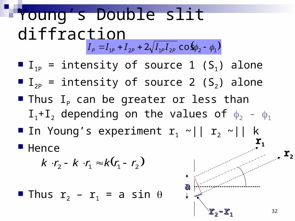
Young’s Double slit diffraction
I1P = intensity of source 1 (S1) alone
I2P = intensity of source 2 (S2) alone
Thus IP can be greater or less than I1+I2 depending on the values of 2 - 1
In Young’s experiment r1 ~|| r2 ~|| k Hence
Thus r2 – r1 = a sin
122121 cos2 PPPPP IIIII
2112 rrkrkrk
rr22-r-r11
aa
rr11
rr22