1 An Experimental Investigation of SIMO, MIMO,Interference-alignment (IA) and Coordinated...
29
1 An Experimental Investigation of SIMO, MIMO,Interference-alignment (IA) and Coordinated Multi-Point (CoMP)” Per Zetterberg and Nima N. Moghadam INTERNATIONAL CONFERENCE ON SYSTEMS, SIGNALS AND IMAGE PROCESSING (IWSSIP)
-
Upload
kevin-watkins -
Category
Documents
-
view
219 -
download
2
Transcript of 1 An Experimental Investigation of SIMO, MIMO,Interference-alignment (IA) and Coordinated...
1
An Experimental Investigation of SIMO, MIMO,Interference-alignment (IA) and Coordinated Multi-Point (CoMP)”
Per Zetterberg and Nima N. Moghadam
INTERNATIONAL CONFERENCE ON SYSTEMS,SIGNALS AND IMAGE PROCESSING (IWSSIP)
2
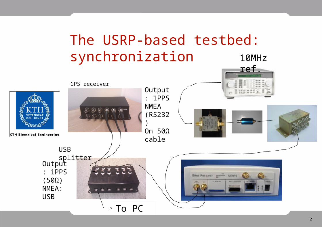
The USRP-based testbed: synchronization
GPS receiverOutput: 1PPSNMEA (RS232)On 50Ω cable
Output: 1PPS (50Ω) NMEA: USB
USB splitter
10MHz ref.
To PC
3
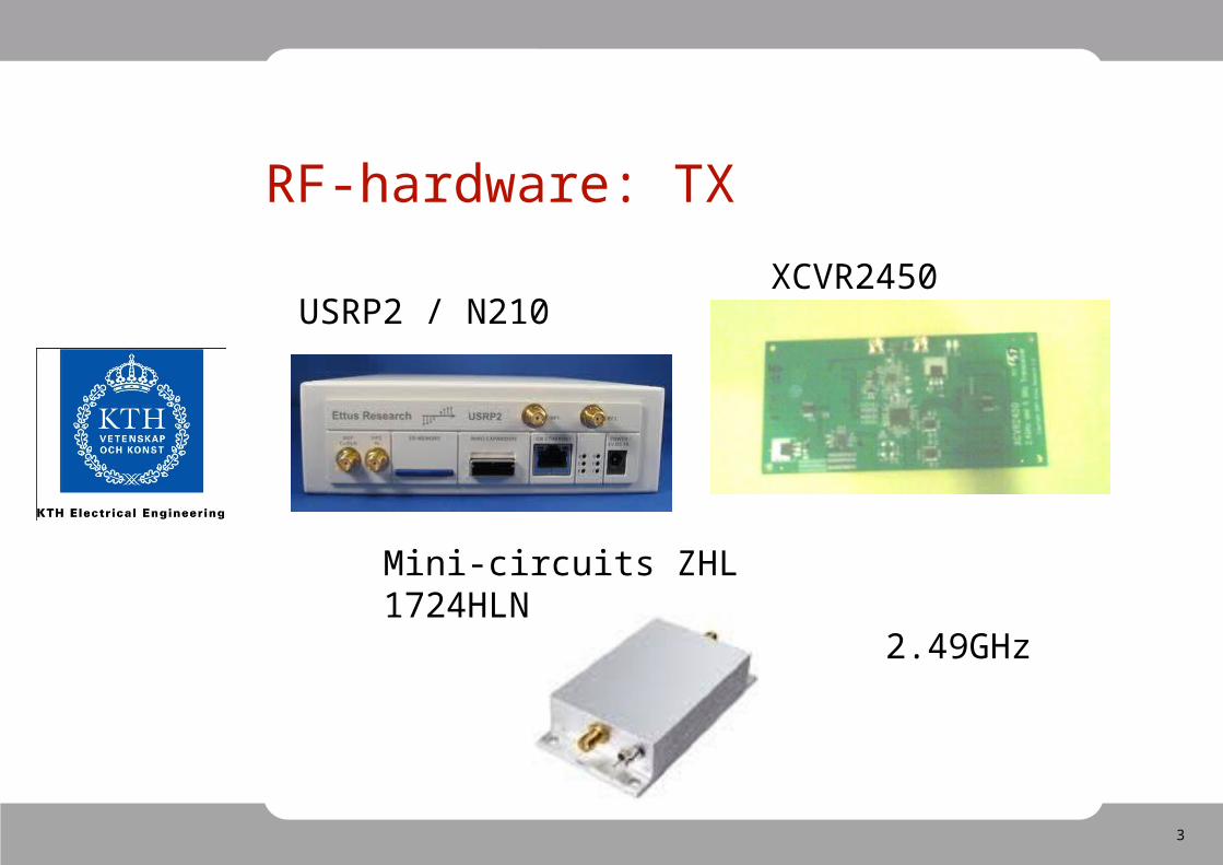
RF-hardware: TX
USRP2 / N210XCVR2450
Mini-circuits ZHL 1724HLN
2.49GHz
4
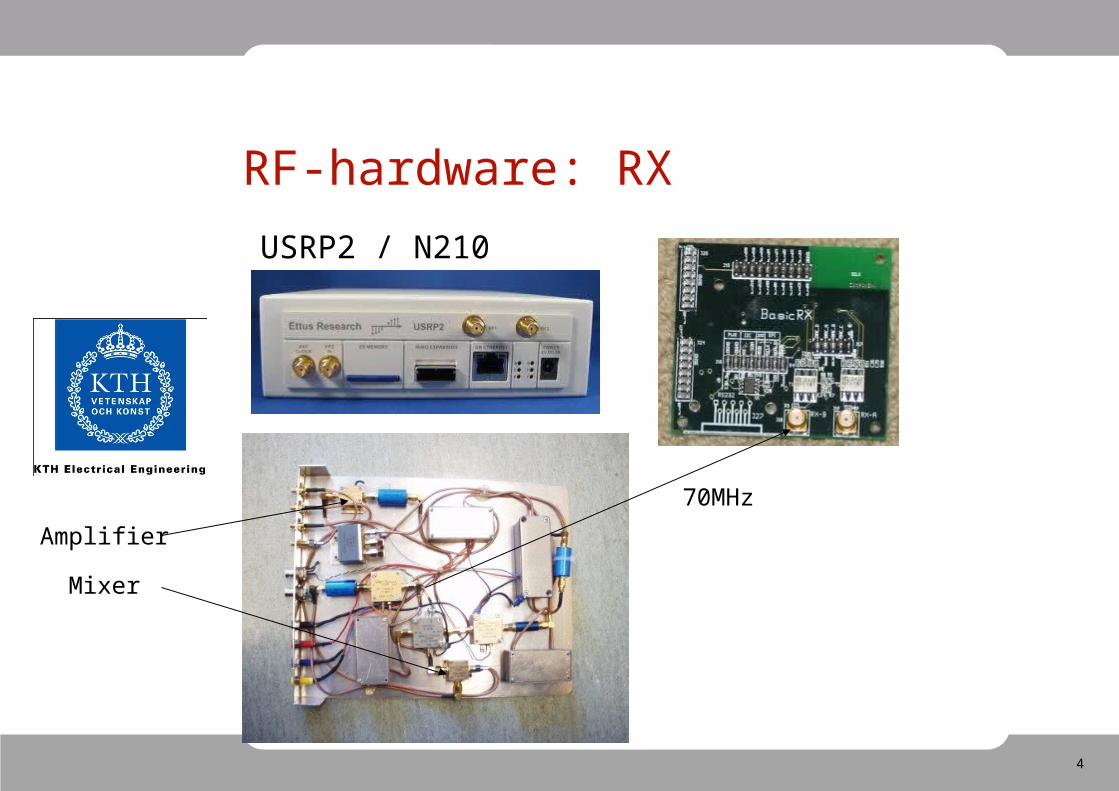
RF-hardware: RX
USRP2 / N210
Amplifier
Mixer
70MHz
5
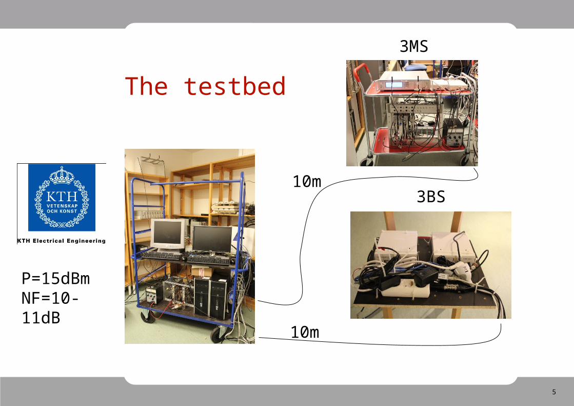
The testbed
3BS
10m
10m
3MS
P=15dBmNF=10-11dB
6
The 4Multi Software FrameWork(Multi-Antenna, Multi-User, Multi-Cell, Multi-Band)
• Send data in small bursts (relaxes computational load)• Nodes synchronized by external trigering (PPS)• The implementor (basically) only need to program three functions node::init, node::process and node::end_of_run.• Simulate the system using “simulate” generic function.• Everything that can be compiled with gcc can run (e.g IT++)• Toolbox with coding&modulation.• Store _all_ received signals for post-processing.
Vision: “The coding should be as easy as performing ordinary
(but detailed) desktop simulations”
7
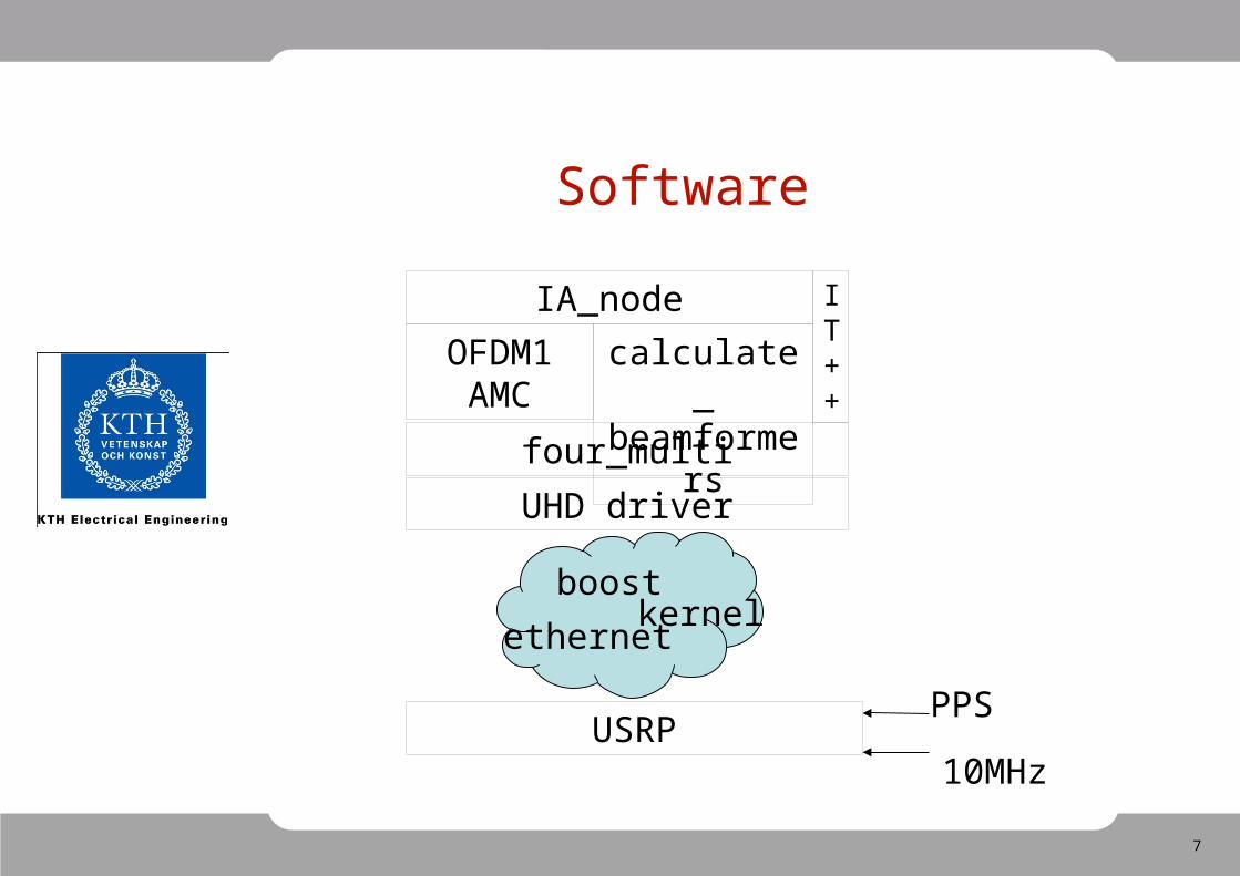
Software
UHD driver
four_multi
boost
ethernetkernel
OFDM1AMC
IA_node
calculate_beamformers
IT++
USRPPPS
10MHz
8
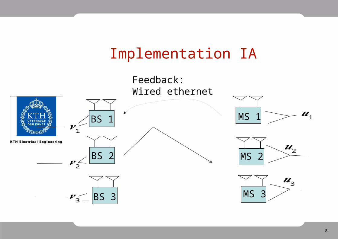
Implementation IA
BS 1
BS 2
BS 3
MS 1
MS 2
MS 3
Feedback:Wired ethernet
𝒗 1
𝒗 2
𝒗 3
𝒖1
𝒖2
𝒖3
9
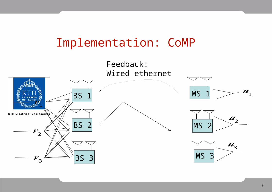
Implementation: CoMP
BS 1
BS 2
BS 3
MS 1
MS 2
MS 3
Feedback:Wired ethernet
𝒗 1
𝒗 2
𝒗 3
𝒖1
𝒖2
𝒖3
10
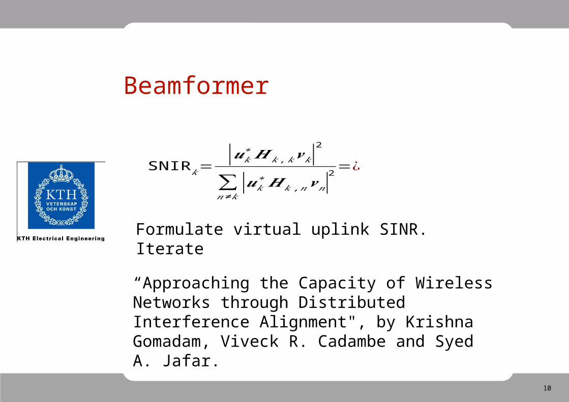
Beamformer
SNIR𝑘=|𝒖𝑘
∗𝑯𝑘 ,𝑘𝒗𝑘|2
∑𝑛 ≠𝑘
|𝒖𝑘∗𝑯𝑘 ,𝑛𝒗𝑛|
2 =¿
“Approaching the Capacity of Wireless Networks through Distributed Interference Alignment", by Krishna Gomadam, Viveck R. Cadambe and Syed A. Jafar.
Formulate virtual uplink SINR. Iterate
11
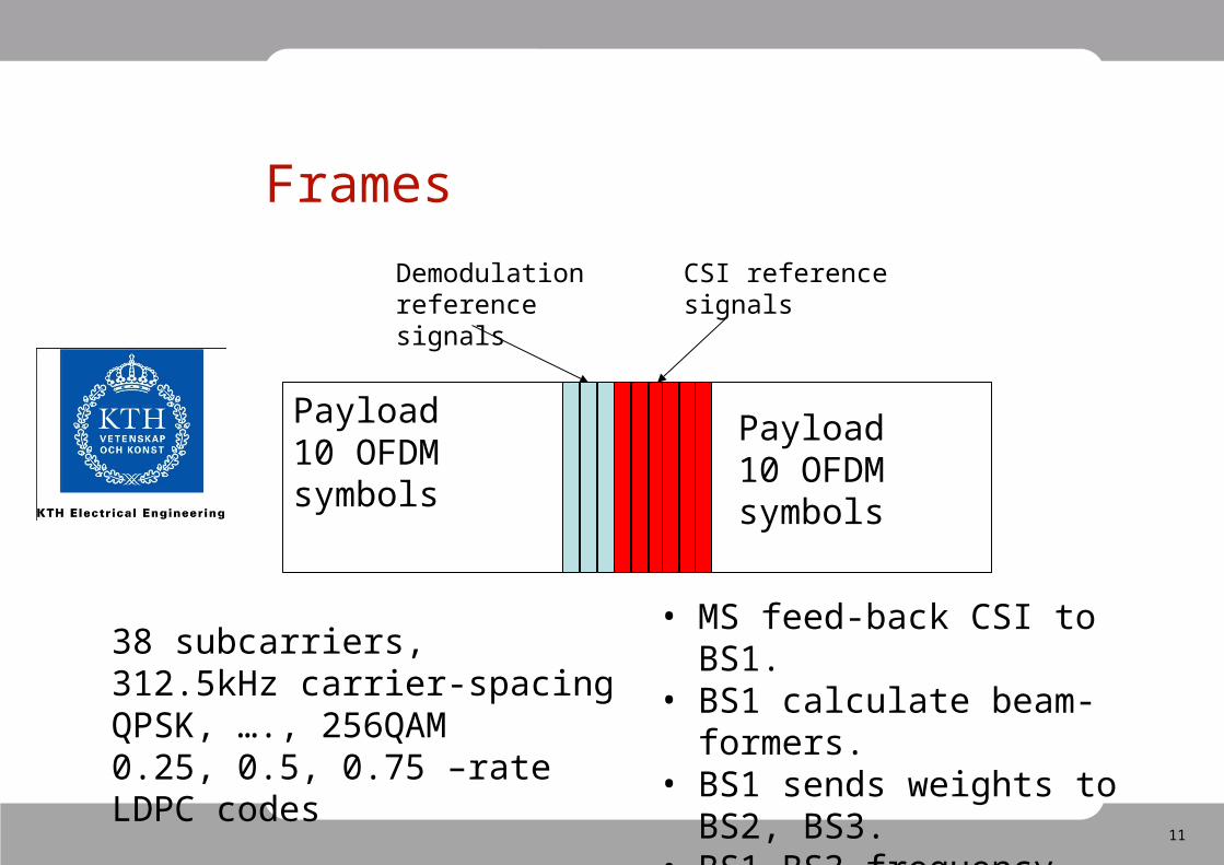
Frames
Payload10 OFDM symbols
Payload10 OFDM symbols
CSI referencesignals
Demodulation reference signals
38 subcarriers, 312.5kHz carrier-spacingQPSK, …., 256QAM0.25, 0.5, 0.75 –rate LDPC codes
• MS feed-back CSI to BS1.• BS1 calculate beam-formers.• BS1 sends weights to BS2,
BS3.• BS1-BS3 frequency locked.
12
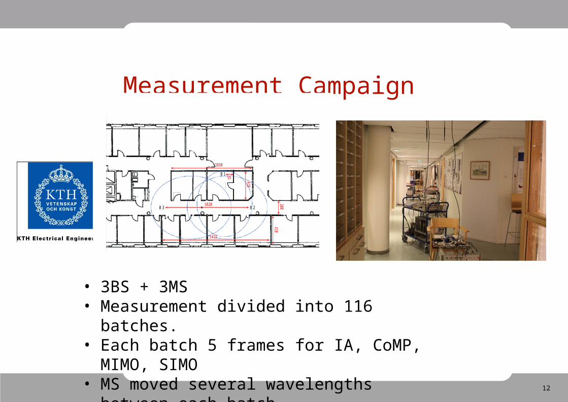
Measurement Campaign
• 3BS + 3MS• Measurement divided into 116 batches.• Each batch 5 frames for IA, CoMP, MIMO, SIMO• MS moved several wavelengths between each
batch.
B 1
B 2 B 3
410
410
1030
200
55
1020
1415
*
13
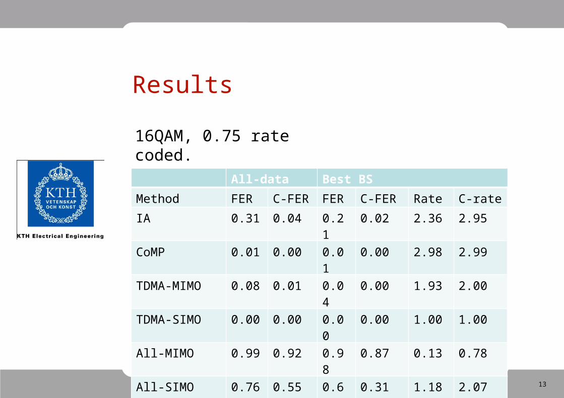
Results
16QAM, 0.75 rate coded. .
All-data Best BS
Method FER C-FER FER C-FER Rate C-rate
IA 0.31 0.04 0.21 0.02 2.36 2.95
CoMP 0.01 0.00 0.01 0.00 2.98 2.99
TDMA-MIMO 0.08 0.01 0.04 0.00 1.93 2.00
TDMA-SIMO 0.00 0.00 0.00 0.00 1.00 1.00
All-MIMO 0.99 0.92 0.98 0.87 0.13 0.78
All-SIMO 0.76 0.55 0.61 0.31 1.18 2.07

14
How far from ideal ?
15
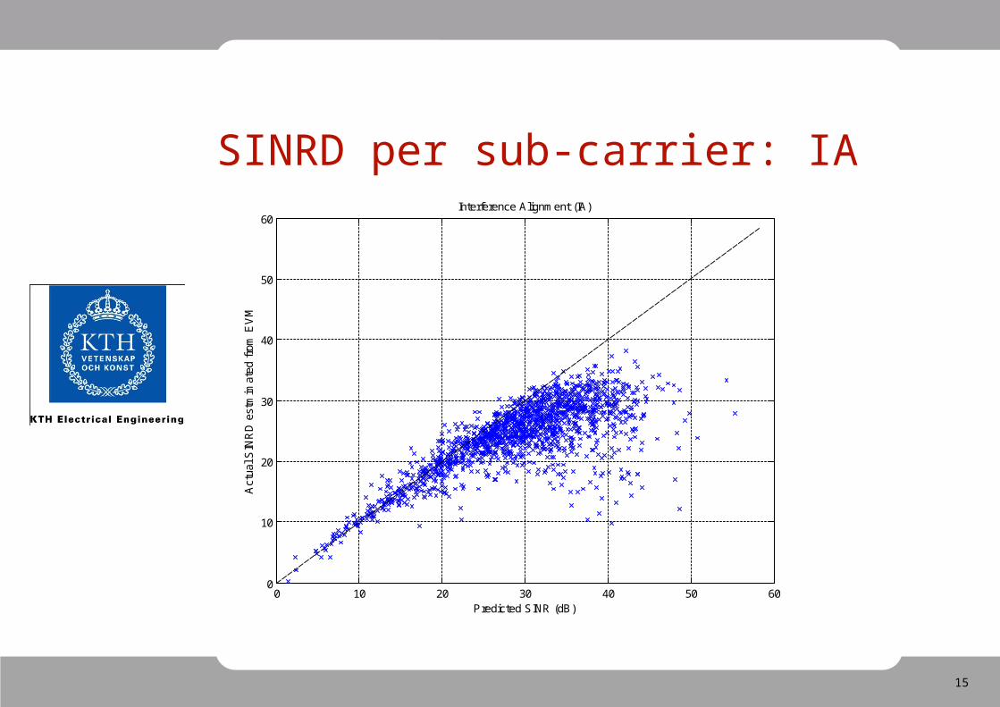
SINRD per sub-carrier: IA
0 10 20 30 40 50 600
10
20
30
40
50
60Interference Alignment (IA)
Predicted SINR (dB)
Act
ual S
INR
D e
stm
imat
ed f
rom
EV
M
16
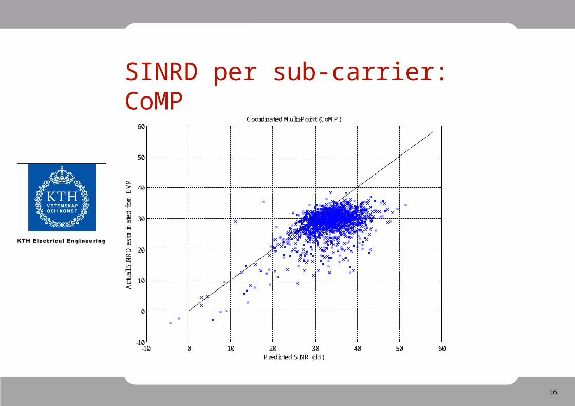
SINRD per sub-carrier: CoMP
-10 0 10 20 30 40 50 60-10
0
10
20
30
40
50
60Coordinated Multi-Point (CoMP)
Predicted SINR (dB)
Act
ual S
INR
D e
stm
imat
ed f
rom
EV
M
17
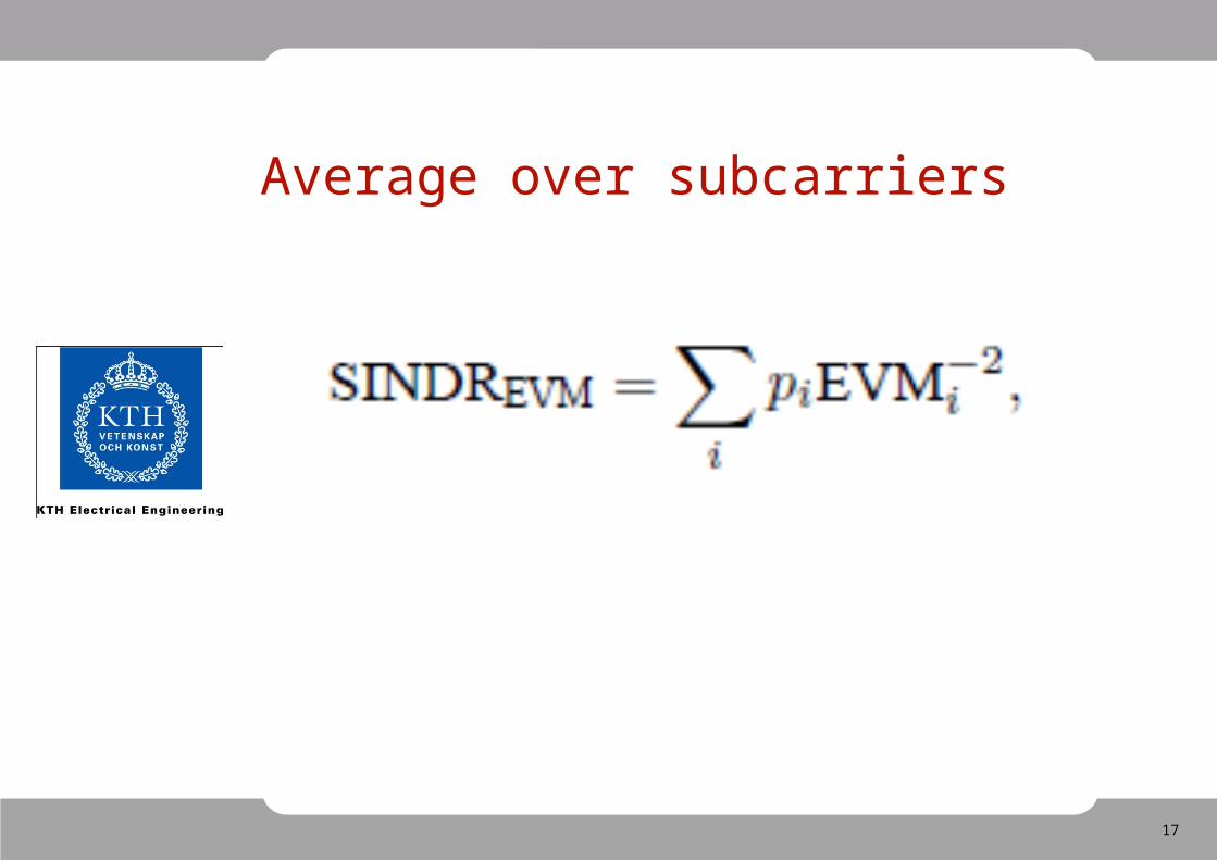
Average over subcarriers
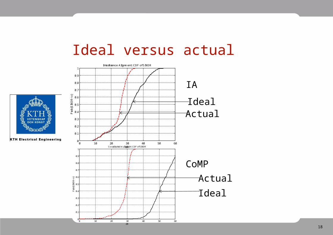
18
Ideal versus actual
IA
CoMP
0 10 20 30 40 50 600
0.1
0.2
0.3
0.4
0.5
0.6
0.7
0.8
0.9
1Co-ordinated multi-point: CDF of SINDR
dB
Pro
b{S
IND
R<
x}
0 10 20 30 40 50 600
0.1
0.2
0.3
0.4
0.5
0.6
0.7
0.8
0.9
1Interference Alignment: CDF of SINDR
dB
Pro
b{S
IND
R<
x}
IdealActual
Actual
Ideal
19
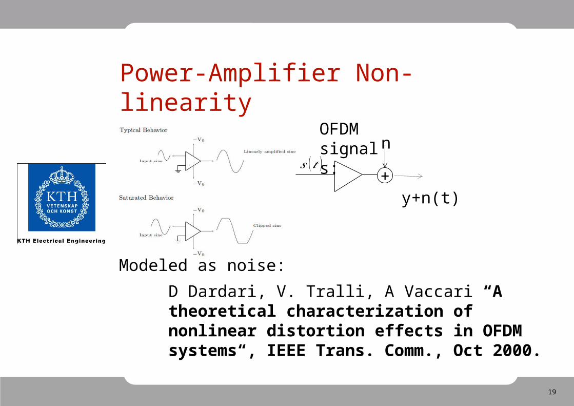
Power-Amplifier Non-linearity
OFDM signals:
+𝑠 (𝑡 )
n
y+n(t)
Modeled as noise:
D Dardari, V. Tralli, A Vaccari “A theoretical characterization of nonlinear distortion effects in OFDM systems“, IEEE Trans. Comm., Oct 2000.
20
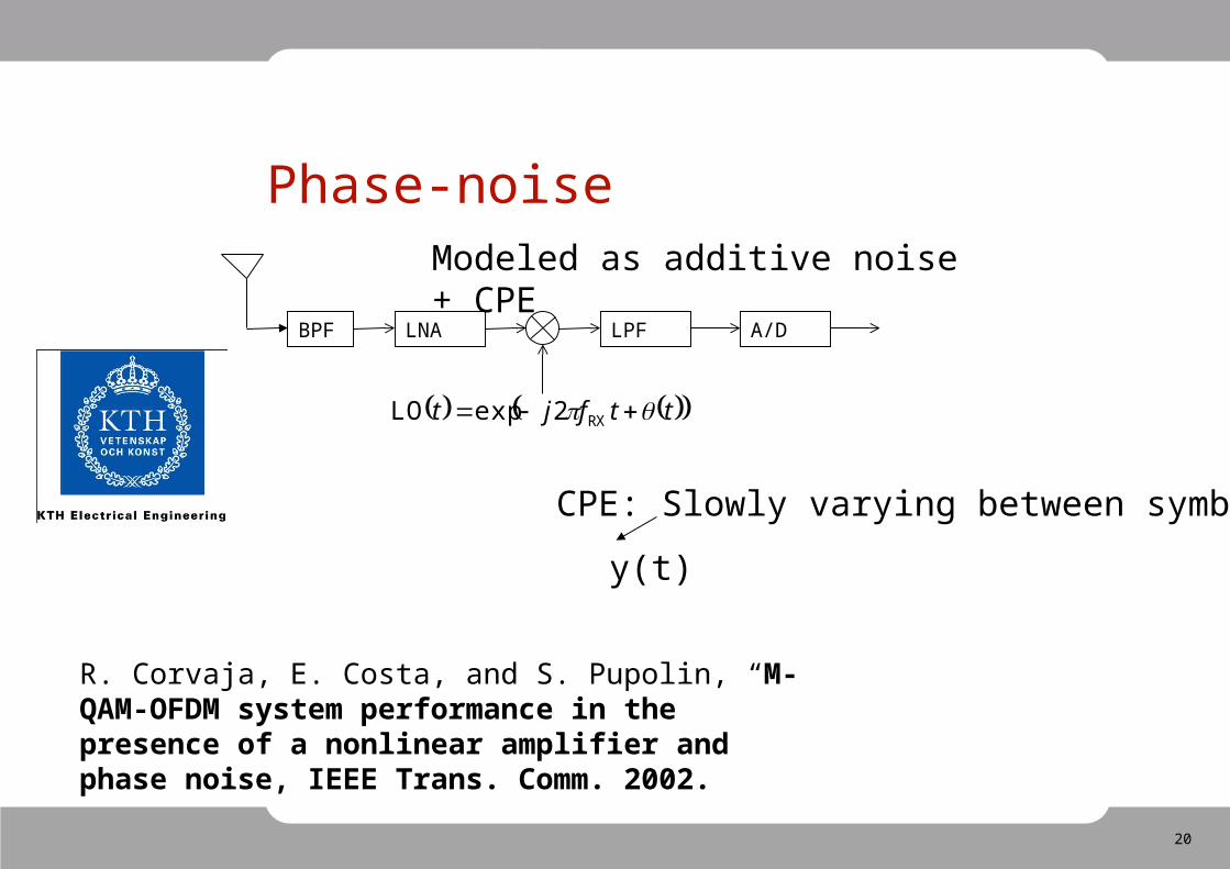
Phase-noise
A/D
ttfjt RX2expLO
LPFBPF LNA
y(t)
Modeled as additive noise + CPE
CPE: Slowly varying between symbols
R. Corvaja, E. Costa, and S. Pupolin, “M-QAM-OFDM system performance in the presence of a nonlinear amplifier and phase noise, IEEE Trans. Comm. 2002.
21
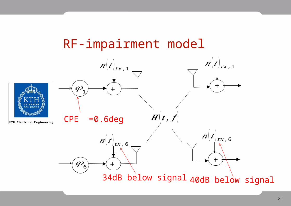
RF-impairment model
𝜑1 +
𝑛 (𝑡 )tx ,1
𝜑6
𝑛 (𝑡 )tx , 6
+
𝑯 (𝒕 , 𝒇 )
+
𝑛 (𝑡 )rx ,1
+
𝑛 (𝑡 )rx , 6
CPE =0.6deg
34dB below signal 40dB below signal
22
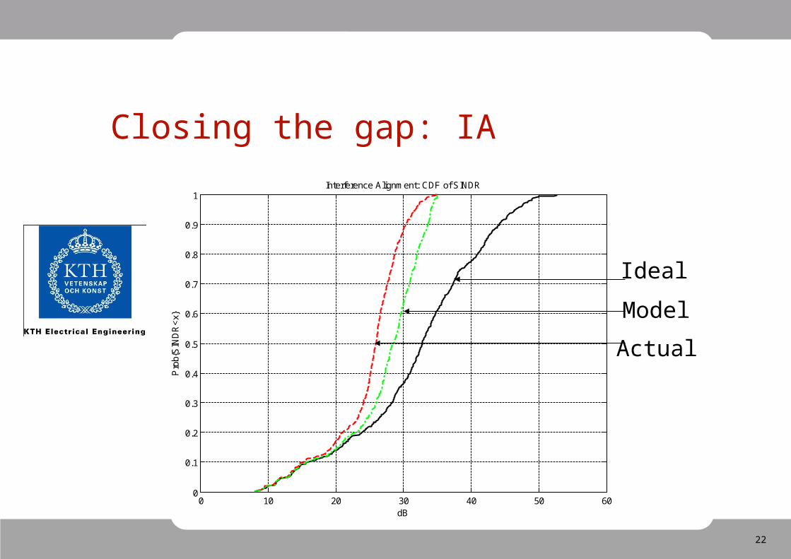
Closing the gap: IA
0 10 20 30 40 50 600
0.1
0.2
0.3
0.4
0.5
0.6
0.7
0.8
0.9
1Interference Alignment: CDF of SINDR
dB
Pro
b{S
IND
R<
x}
Ideal
Actual
Model
23
-10 0 10 20 30 40 50 60 700
0.1
0.2
0.3
0.4
0.5
0.6
0.7
0.8
0.9
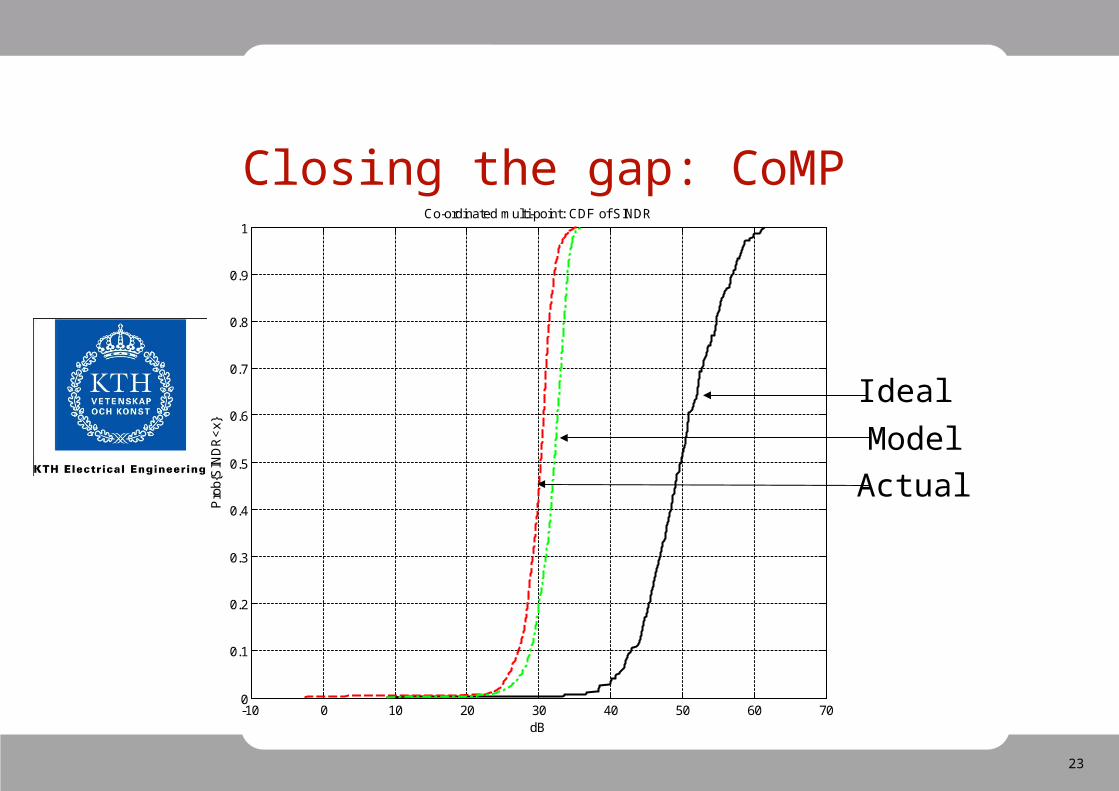
1Co-ordinated multi-point: CDF of SINDR
dB
Pro
b{S
IND
R<
x}
Closing the gap: CoMP
Ideal
Model
Actual
24
0 10 20 30 40 50 600
0.1
0.2
0.3
0.4
0.5
0.6
0.7
0.8
0.9
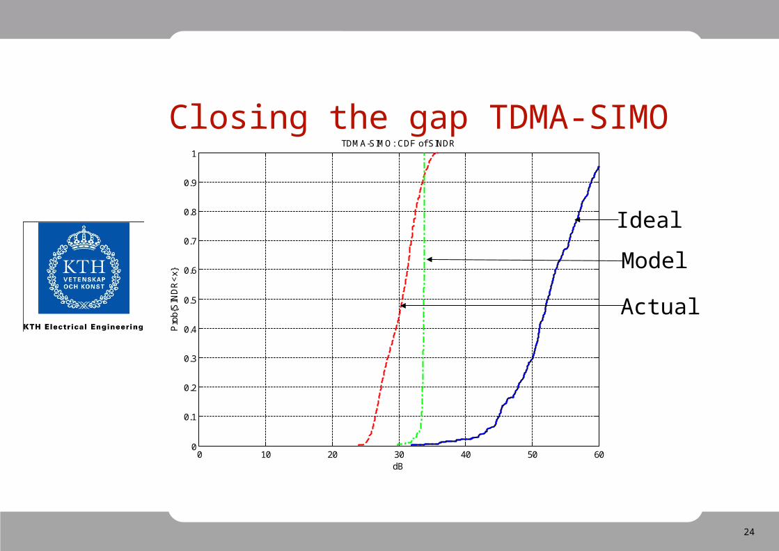
1TDMA-SIMO: CDF of SINDR
dB
Pro
b{S
IND
R<
x}
Closing the gap TDMA-SIMO
Ideal
Model
Actual
25
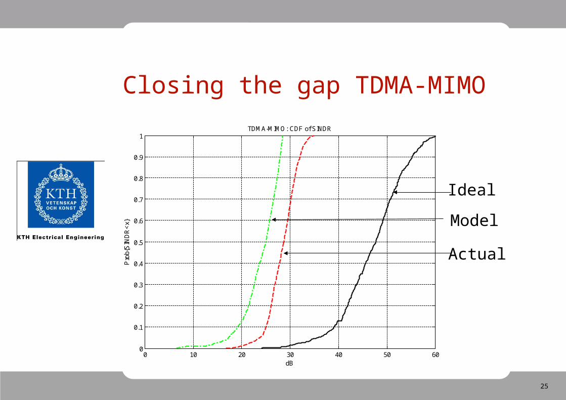
Closing the gap TDMA-MIMO
0 10 20 30 40 50 600
0.1
0.2
0.3
0.4
0.5
0.6
0.7
0.8
0.9
1TDMA-MIMO: CDF of SINDR
dB
Pro
b{S
IND
R<
x}
Ideal
Model
Actual
26
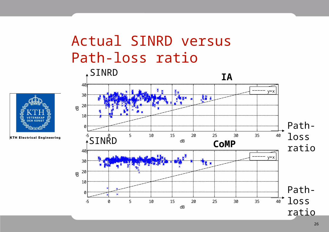
Actual SINRD versus Path-loss ratio
-5 0 5 10 15 20 25 30 35 40
0
10
20
30
40
dB
dB
y=x
-5 0 5 10 15 20 25 30 35 40
0
10
20
30
40
dB
dB
y=x
Path-loss ratio
Path-loss ratio
SINRD
SINRD
IA
CoMP
27
Conclusion
• CoMP and IA implemented on a wireless test-bed.• Both IA and CoMP perform better than reference
schemes SIMO and MIMO.• CoMP provides best performance.
• Small hardware impairments degrade performance significantly in particular CoMP.
• Impairment model proposed - fair agrement with measurements => test on more complex scenarios.
• Hardware characterization can be improved.
28
Next step
• Implement adaptive modulation and coding.
• More streams in CoMP.
• Model hardware with detailed AM/AM, AM/PM and phase-
noise spectrums.
29
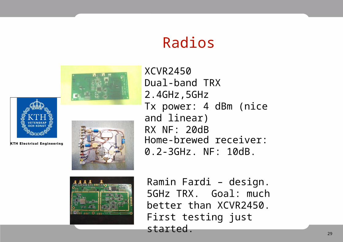
Radios
XCVR2450Dual-band TRX 2.4GHz,5GHzTx power: 4 dBm (nice and linear)RX NF: 20dB
Home-brewed receiver:0.2-3GHz. NF: 10dB.
Ramin Fardi – design.5GHz TRX. Goal: much better than XCVR2450. First testing just started.