Lecture 29 OFDM Synchronizationwireless-systems.ece.gatech.edu/6604/lectures/OFDM-synch.pdf · MIMO...
30
Lecture 29 OFDM Synchronization
Transcript of Lecture 29 OFDM Synchronizationwireless-systems.ece.gatech.edu/6604/lectures/OFDM-synch.pdf · MIMO...
Lecture 29OFDM Synchronization

A MULTI INPUT MULTI OUTPUT (MIMO) OFDM SYSTEM
• A MIMO system uses Q Transmit antennas and L Receive Antennas

Q-TRANSMIT L-RECEIVE MIMO OFDM SYSTEM
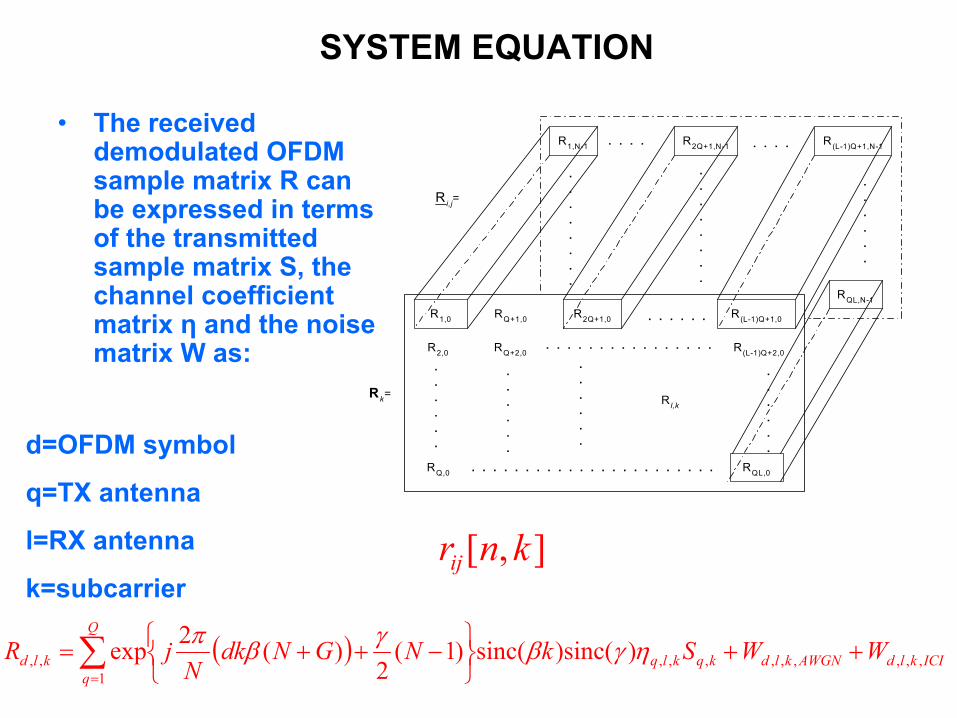
SYSTEM EQUATION
• The received demodulated OFDM sample matrix R can be expressed in terms of the transmitted sample matrix S, the channel coefficient matrix η and the noise matrix W as:
.
.
.
.
.
.
.
.
.
.
.
.
.
.
.
.
.
.
.
.
.
.
R1,0 R(L-1)Q+1,0R2Q+1,0RQ+1,0
RQ,0
RQ+2,0 R(L-1)Q+2,0R2,0. . . . . . . . . . . . . . . .
.
.
.
.
.
.
.
.
.
.
.
.
.
.
.
.
.
.
.
.
.
.
.
.. . . . . . . . . . . . . . . . . . . . . . . RQL,0
R l,k
R1,N-1 R2Q+1,N-1
. . . . . .
. . . .
Rk=
. . . .
RQL,N-1
R i,j=
R(L-1)Q+1,N-1
],[ knrij
( ) ICIkld
Q
qAWGNkldkqklqkld WWSkNGNdk
NjR ,,,
1,,,,,,,, ))sinc(sinc()1(
2)(2exp ++
−++=∑
=
ηγβγβπ
d=OFDM symbol
q=TX antenna
l=RX antenna
k=subcarrier
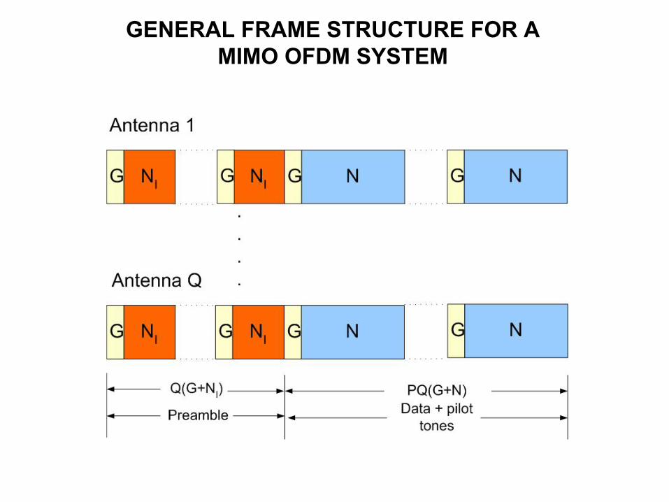
GENERAL FRAME STRUCTURE FOR A MIMO OFDM SYSTEM
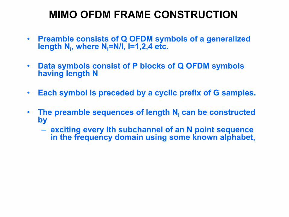
MIMO OFDM FRAME CONSTRUCTION
• Preamble consists of Q OFDM symbols of a generalized length NI, where NI=N/I, I=1,2,4 etc.
• Data symbols consist of P blocks of Q OFDM symbols having length N
• Each symbol is preceded by a cyclic prefix of G samples.
• The preamble sequences of length NI can be constructed by – exciting every Ith subchannel of an N point sequence
in the frequency domain using some known alphabet,

MIMO OFDM FRAME CONSTRUCTION (Contnd.)
– Taking an N-point IFFT of the sequence, – Keep the first NI samples and discarding the rest,– Add a cyclic prefix to the sequence before
transmission.
• Hence the training sequence for the qth symbol in the time domain is given by
∑−
=
−=
=
1
0,, .1,,1,0 2exp1 N
kIkqnq Nn
NnkjS
Ns K
π

CHARACTERISTICS OF GOOD PREAMBLE SEQUENCES AND STRUCTURES
• Good correlation properties for time synchronization
• Low PAPR for high power transmission
• Suitable for channel parameter estimation
• Suitable for frequency offset estimation over a wide range
• Low computational complexity, low overhead but high accuracy

GENERATION OF LENGTH 256 SEQUENCE N=256, I=1
Example: For NI=256 S1=sqrt(2)*[0 1 -1 1 -1 -1 1 -1 1 -1 1 1 1 -1 1 1 -1 -1 1 -1
1 -1 1 -1 1 1 1 -1 -1 -1 1 -1 1 -1 1 1 -1 1 -1 -1 1 -1 -1 -1 -1 1 -1 1 1 1 1 1 -1 -1 -1 1 -1 1 -1 -1 -1 -1 1 -1 -1 -1 1 -1 -1 1 -1 1 1 1 -1 1 -1 1 -1 -1 1 1 -1 -1 1 -1 -1 -1 -1 1 1 1 1 1 -1 -1 -1 -1 1 1 -1 0 0 0 0 0 0 0 0 0 0 0 0 0 0 0 0 0 0 0 0 0 0 0 0 0 0 0 0 0 0 0 0 0 0 0 0 0 0 0 0 0 0 0 0 0 0 0 0 0 0 0 0 0 0 0 -1 -1 1 -1 -1 -1 -1 1 1 -1 1 -1 -1 1 -1 1 1 -1 1 -1 -1 1 1 1 1 -1 1 -1 1 1 -1 1 -1 -1 -1 -1 -1 -1 1 -1 1 1 1 1 1 1 -1 1 1 -1 -1 1 1 1 -1 -1 1 -1 1 1 -1 -1 1 -1 1 1 1 -1 -1 1 1 1 1 1 -1 1 -1 1 -1 1 1 1 1 -1 -1 -1 1 -1 -1 1 1 1 1 1 -1 -1 -1 1 1 -1] PAPR = 5.34 dB
55 0’s come from IEEE802.16a spectral requirements

Example: For NI=128 S1=sqrt(2)*[0 0 -1 0 -1 0 1 0 -1 0 -1 0 1 0 1 0 1
0 -1 0 1 0 1 0 1 0 -1 0 -1 0 -1 0 -1 0 -1 0 -1 0 1 0 -1 0 -1 0 -1 0 -1 0 -1 0 -1 0 1 0 1 0 1 0 -1 0 1 0 -1 0 1 0 1 0 -1 0 1 0 1 0 1 0 -1 0 -1 0 -1 0 -1 0 -1 0 1 0 -1 0 -1 0 1 0 -1 0 -1 0 1 0 -1 {55 0’s} -1 0 1 0 1 0 1 0 1 0 -1 0 -1 0 1 0 -1 0 1 0 -1 0 -1 0 1 0 1 0 -1 0 1 0 -1 0 1 0 -1 0 1 0 -1 0 1 0 1 0 -1 0 1 0 -1 0 -1 0 1 0 -1 0 -1 0 -1 0 1 0 1 0 -1 0 1 0 1 0 1 0 -1 0 1 0 1 0 -1 0 -1 0 -1 0 1 0 1 0 1 0 1 0 1 0 1 0 1 0]
PAPR = 4.31 dB
GENERATION OF LENGTH 128 SEQUENCE N=256, I=2

Example: For NI=64 S1=sqrt(2)*[0 0 0 0 +1+j 0 0 0 -1-j 0 0 0 +1+j 0 0 0 +1-j 0 0 0 +1+j 0
0 0 +1+j 0 0 0 -1+j 0 0 0 +1+j 0 0 0 -1-j 0 0 0 +1+j 0 0 0 +1+j 0 0 0 +1-j 0 0 0 +1+j 0 0 0 +1+j 0 0 0 +1-j 0 0 0 -1-j 0 0 0 +1+j 0 0 0 -1-j 0 0 0 -1-j 0 0 0 -1+j 0 0 0 +1+j 0 0 0 +1+j 0 0 0 +1-j 0 0 0 -1-j 0 0 0 -1+j 0 0 0 -1+j {55 0’s} +1+j 0 0 0 +1+j 0 0 0 +1+j 0 0 0 -1+j 0 0 0 +1+j 0 0 0 -1-j 0 0 0 -1+j 0 0 0 -1-j 0 0 0 -1-j 0 0 0 -1-j 0 0 0 +1+j 0 0 0 -1+j 0 0 0 +1+j 0 0 0 -1-j 0 0 0 +1-j 0 0 0 +1+j 0 0 0 +1+j 0 0 0 +1+j 0 0 0 -1-j 0 0 0 +1-j 0 0 0 +1+j 0 0 0 -1-j 0 0 0 +1-j 0 0 0 +1+j 0 0 0 -1+j 0 0 0 +1-j 0 0 0]
PAPR = 3.00 dB
GENERATION OF LENGTH 64 SEQUENCE N=256, I=4

OFDM SIGNAL ACQUISITION USING PREAMBLE
The preamble at the start of an OFDM frame is used to acquire the OFDM signal and perform:
• Time synchronization• Coarse time synchronization – Step I• Fine time synchronization – Step IV
• Frequency offset estimation• Fractional frequency offset estimation – Step II• Residual frequency offset estimation - Step III
• Channel and noise variance estimation

OFDM SIGNAL ACQUISITION
Step I. Coarse Time Synchronization –• Estimate the start of the OFDM frame over an approximate
range of samples. It must be robust.• Techniques – Perform maximum-likelihood estimation of
the time-of-arrival– The likelihood function is approximated by [van de
Beek]
Where γ is the frequency offset between Tx and Rx local oscillators and φn is given by
( )
∠+≈Λ nn I
n φπγφγ 2cos,
( )∑−
=+++ ⋅=
1
0,
*,
G
kNknjknjn I
rrφ

Frequency Offset Estimation, Step II
Step II. Fractional Frequency Offset Estimation• Extremely important since frequency offset introduces ICI,• Technique – Maximum-likelihood estimation of the
frequency offset
• The function is maximized when the cosine in the likelihood function is maximum. Hence,
opt2ˆML d
I φπ
γ ∠⋅=
( )( )γγγ
,max argˆ optML dΛ=

Residual Frequency Offset Estimation, Step III
• The range of the maximum-likelihood frequency offset estimator is ± I / 2 subchannel spacing.
• This frequency offset estimation/ correction range can be improved using some frequency domain processing.
Step III. Residual Frequency Offset Estimation
• If the same sequence si,n, n=0,…,NI-1 is transmitted from all the antennas then the frequency offset of integral multiples of subchannel spacing can be carried out.
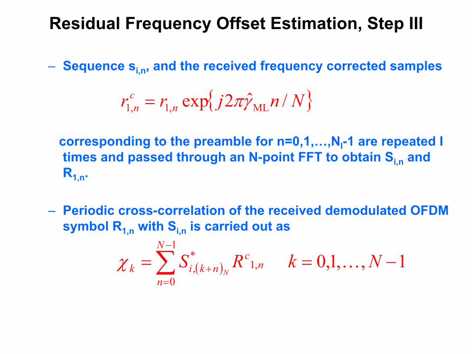
Residual Frequency Offset Estimation, Step III
– Sequence si,n, and the received frequency corrected samples
corresponding to the preamble for n=0,1,…,NI-1 are repeated I times and passed through an N-point FFT to obtain Si,n and R1,n.
– Periodic cross-correlation of the received demodulated OFDM symbol R1,n with Si,n is carried out as
( ) 1,,1,0 1
0,1
*, −==∑
−
=+ NkRS
N
nn
cnkik N
Kχ
{ }Nnjrr ncn /ˆ2exp ML,1,1 γπ=

Residual Frequency Offset Estimation, Step III
– The residual frequency offset of an integral number of subchannel spacing is obtained as
– The residual frequency offset estimate can be sent to thelocal oscillator (NCO) for offset correction.
{ }kkχmax argˆ =Γ
Γ̂

Fine Time Synchronization, Step IV
Step IV. Fine Time Synchronization• Fine time synchronization is needed to obtain start of the
OFDM frame to within a few samples,• It can be carried out by cross-correlating the received
frequency offset corrected samples with the transmitted sequence as
• If same sequence is transmitted from all the antennas then only one cross-correlator is needed.
LjrsQ
i
N
k
cknjkin ,...,1 ,
1
1
0,
*, ==∑∑
=
−
=+ψ

PARAMETER ESTIMATION
Channel Estimation for MIMO OFDM Systems• Step I. –
–LS Estimation using Q symbols
.1,.,0 RS RSη 1 −=== − INIk IkkkHkk K

PARAMETER ESTIMATION
• Step II. – Interpolation in the Frequency Domain Channel estimates are needed for all the tones, however, they are available for only NI tones. If channel statistics are not available at the receiver then frequency domain (linear) interpolation may be used otherwise MMSE interpolation may be used.
COMMERCIAL OFDM SYSTEMS
• In commercial OFDM systems, the tone at d.c. and the tones near the band-edges are set to zero.
• This is called zero-padding, or subchannel nulling and the zero-padded tones are called virtual subchannels.
• For example in IEEE 802.16a/b Broadband Fixed Wireless Access systems, out of N=256, 56 tones are set to zero. Hence the number of tones used Nu=200.
• Before employing Method I for MSE reduction, frequency domain extrapolation is needed.

MSE REDUCTION IN FREQUENCY DOMAIN
• MSE reduction can be carried out in the frequency domain itself. One of the simplest methods is frequency domain smoothing.
• Keep the tones from the coarse channel estimates near the band-edges as they are and perform averaging on all the other tones using
2ˆ 1,1,
,+− +
= kijkijkij
ηηη

SIGNAL TRANSMISSION MATRIX DESIGN
• Need unitary Sks in order to generate Q OFDM symbols of a generalized length NI for channel estimation.
• The simplest unitary structure is obtained when the signal transmission matrix is diagonal – Direct extension of SISO– The transmitted power needs
to be increased by a factor of Q in the training phase. Hence, it requires power amplifiers with an increased dynamic range.
=
4
3
2
1
000000000000
S
S
S
S
S
D

• For Q=2, Alamouti’ s structure is optimal
• For Q=4 and 8, orthogonal signal sets can be used, e.g. for Q=4,
=
− *1
*2
21SSS
SS
A
=
− *1
*1
11SSS
SS
AS
=
−−
−−
−−
1111
1111
1111
1111
S
SSSS
SSSS
SSSS
SSSS
TS
SIGNAL TRANSMISSION MATRIX DESIGN

SIMULATION RESULTS FOR SIGNAL ACQUISITION
• Simulations for the system performance are carried out for an IEEE802.16a Broadband Fixed Wireless Access System.
• The fixed wireless access channel is characterized by the Stanford University Interim (SUI) models.
• SUI-4 Channel Model for moderate to heavy tree densities is given by:
Hz0.250.150.2fm
dB-8-40Power
µS41.50Delay
UnitsTap3Tap2Tap1

( )mfff
ffff
fS =
>≤+−
= 00
04
02
0
101784.072.11
•Autocorrelation Function and PSD for a SUI Channel Tap are as shown
•The Doppler power spectrum for the SUI channel taps is approximated by
SIMULATION RESULTS FOR SIGNAL ACQUISITION

• Bandwidth = 3.5 MHz, Block size N = 256, Guard G = 64, Modulation type – 16-QAM, P=Number of space-time blocks per frame=10, No channel coding employed,
• Rate 1 space-time block code (STBC) used for a 2X2 system and rate ¾ STBC used for a 4X4 system.
• Total frequency offset Γ+γ = 1+0.25 subchannel spacing,• Number of tones used, Nu=200,• Training sequences used are those proposed for
IEEE802.16a.
SIMULATION RESULTS
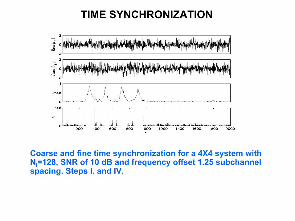
TIME SYNCHRONIZATION
Coarse and fine time synchronization for a 4X4 system with NI=128, SNR of 10 dB and frequency offset 1.25 subchannel spacing. Steps I. and IV.
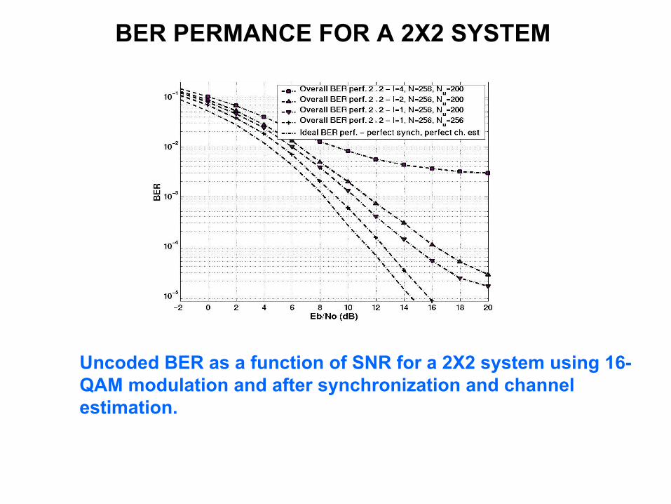
BER PERMANCE FOR A 2X2 SYSTEM
Uncoded BER as a function of SNR for a 2X2 system using 16-QAM modulation and after synchronization and channel estimation.

Uncoded BER as a function of SNR for a 4X4 system using 16-QAM modulation and after synchronization and channel estimation.
BER PERMANCE FOR A 4X4 SYSTEM


![EE6604 Personal & Mobile Communications Week12 …wireless-systems.ece.gatech.edu/6604/2014-lectures/w… · · 2013-11-12[Ss˜˜s(f −fc)+S˜ss˜(−f −fc)] 3. POWER SPECTRAL](https://static.fdocument.org/doc/165x107/5ae6e3ea7f8b9a9e5d8e564f/ee6604-personal-mobile-communications-week12-wireless-2013-11-12sssf.jpg)