ελληνικά αγγλικά...Ελληνικά €Πιάτα Μουσακάς Γεμιστά με τομάτα και πιπεριά Σουτζουκάκια Σμυρνέικα
1
English .......................................................................................................................2
Svenska .................................................................................................................15
Norsk .......................................................................................................................28
Dansk ......................................................................................................................41
Suomi ......................................................................................................................54
Deutsch ..................................................................................................................68
Netherlands ..................................................................................................... 81
Français .................................................................................................................95
Italiano .................................................................................................................110
Español ...............................................................................................................124
Português ..........................................................................................................137
Ελληνικά .............................................................................................................150
Polski ....................................................................................................................164
Eesti.......................................................................................................................177
Lietuviškai .........................................................................................................189
Latviski.................................................................................................................204
Pycckий ..............................................................................................................218
2
EnglishSpecificationReading 0,005 mm Accuracy ± 0,005 mm Power 240 VTemperature operation 0 – 45 °CTemperature storage -30 – 70 °CHumidity max 90 % CE Low voltage directive 73/23/EEC samt 89/336/EEC.
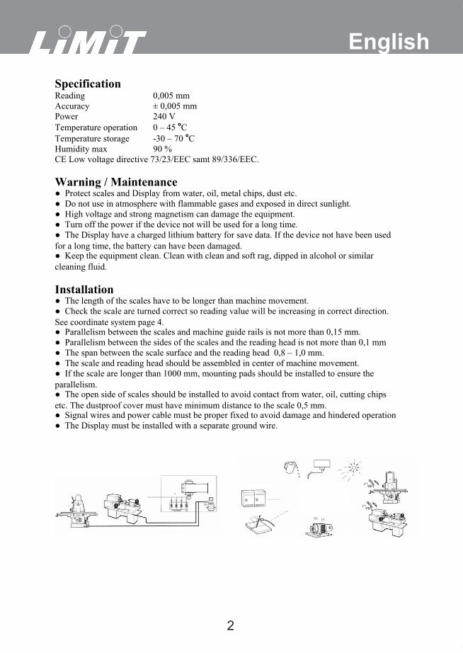
Warning / Maintenance � Protect scales and Display from water, oil, metal chips, dust etc. � Do not use in atmosphere with flammable gases and exposed in direct sunlight. � High voltage and strong magnetism can damage the equipment. � Turn off the power if the device not will be used for a long time. � The Display have a charged lithium battery for save data. If the device not have been used for a long time, the battery can have been damaged. � Keep the equipment clean. Clean with clean and soft rag, dipped in alcohol or similar cleaning fluid.
Installation� The length of the scales have to be longer than machine movement. � Check the scale are turned correct so reading value will be increasing in correct direction. See coordinate system page 4. � Parallelism between the scales and machine guide rails is not more than 0,15 mm. � Parallelism between the sides of the scales and the reading head is not more than 0,1 mm � The span between the scale surface and the reading head 0,8 – 1,0 mm. � The scale and reading head should be assembled in center of machine movement. � If the scale are longer than 1000 mm, mounting pads should be installed to ensure the parallelism. � The open side of scales should be installed to avoid contact from water, oil, cutting chips etc. The dustproof cover must have minimum distance to the scale 0,5 mm. � Signal wires and power cable must be proper fixed to avoid damage and hindered operation � The Display must be installed with a separate ground wire.
3
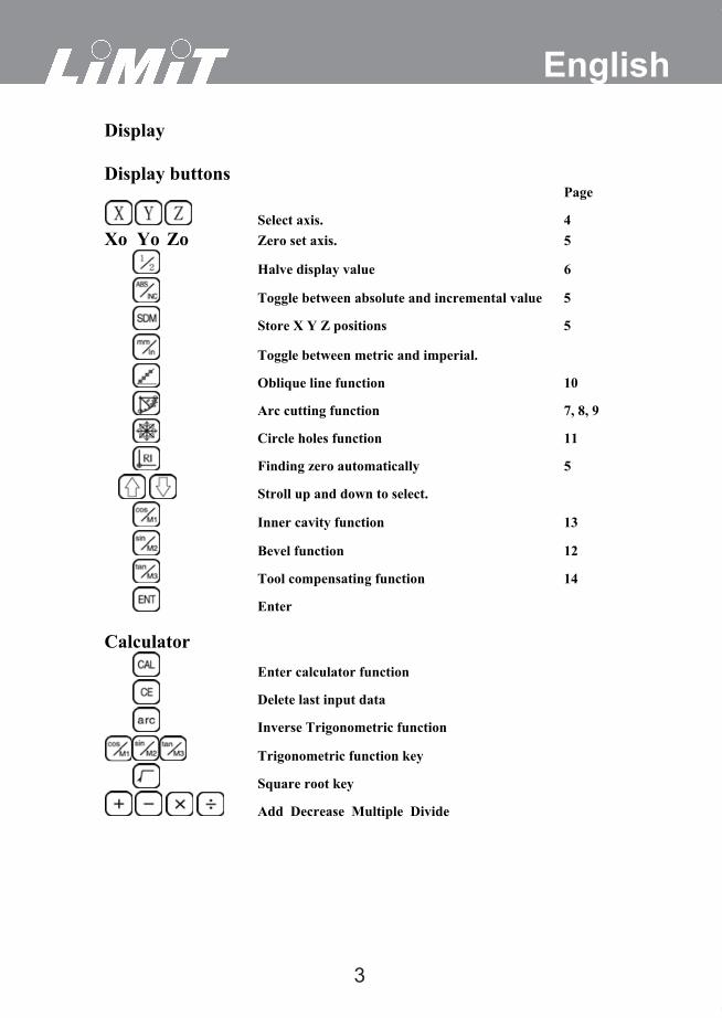
EnglishDisplay
Display buttons Page
Select axis. 4 Xo Yo Zo Zero set axis. 5
Halve display value 6
Toggle between absolute and incremental value 5
Store X Y Z positions 5
Toggle between metric and imperial.
Oblique line function 10
Arc cutting function 7, 8, 9
Circle holes function 11
Finding zero automatically 5
Stroll up and down to select.
Inner cavity function 13
Bevel function 12
Tool compensating function 14
Enter
Calculator Enter calculator function
Delete last input data
Inverse Trigonometric function
Trigonometric function key
Square root key
Add Decrease Multiple Divide
4
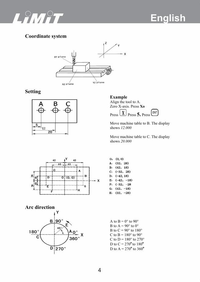
EnglishCoordinate system
SettingExampleAlign the tool to A. Zero X-axis. Press Xo
Press Press 5. Press
Move machine table to B. The display sh shows 12.000
Move machine table to C. The display shows 20.000
Arc direction
A to B = 0° to 90°B to A = 90° to 0° B to C = 90° to 180° C to B = 180° to 90° C to D = 180° to 270°D to C = 270° to 180°D to A = 270° to 360°
44 A till D = 360° till 270
5
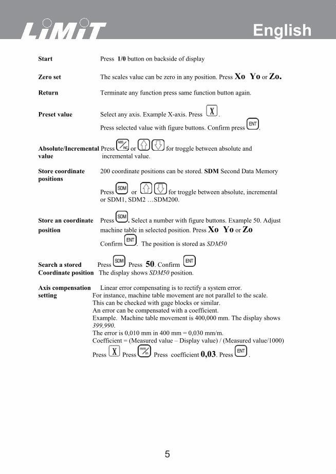
EnglishStart Press 1/0 button on backside of display Zero set The scales value can be zero in any position. Press Xo Yo or Zo.Return Terminate any function press same function button again.
Preset value Select any axis. Example X-axis. Press .
Press selected value with figure buttons. Confirm press .
Absolute/Incremental Press or for troggle between absolute and value incremental value. Store coordinate 200 coordinate positions can be stored. SDM Second Data Memory positions
Press or for troggle between absolute, incrementalor SDM1, SDM2 …SDM200.
Store an coordinate Press . Select a number with figure buttons. Example 50. Adjust position machine table in selected position. Press Xo Yo or Zo
Confirm . The position is stored as SDM50
Search a stored Press Press 50. Confirm Coordinate position The display shows SDM50 position.
Axis compensation Linear error compensating is to rectify a system error. setting For instance, machine table movement are not parallel to the scale. This can be checked with gage blocks or similar.
An error can be compensated with a coefficient. Example. Machine table movement is 400,000 mm. The display shows 399,990.
The error is 0,010 mm in 400 mm = 0,030 mm/m. Coefficient = (Measured value – Display value) / (Measured value/1000)
Press Press Press coefficient 0,03. Press .
6
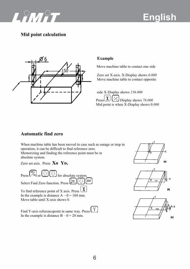
EnglishMid point calculation
Example
Move machine table to contact one side
Zero set X-axis. X-Display shows 0.000 Move machine table to contact opposite side
side X-Display shows 156.000
Press Display shows 78.000 Mid point is when X-Display shows 0.000
Automatic find zero
When machine table has been moved in case such as outage or stop in operation, it can be difficult to find reference zero. Memorizing and finding the reference point must be in absolute system. Zero set axis. Press Xo Yo.
Press or for absolute system.
Select Find Zero function. Press
To find reference point of X axis. Press In the example is distance A – 0 = 104 mm. Move table until X-axis shows 0.
Find Y-axis referencepoint in same way. Press In the example is distance B – 0 = 20 mm.
7
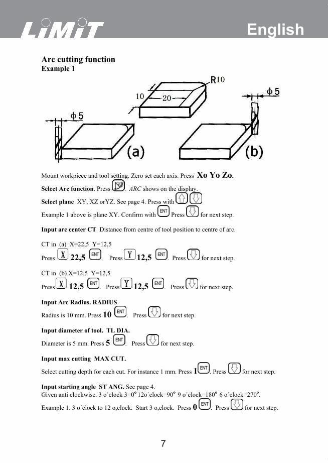
EnglishArc cutting functionExample 1
Mount workpiece and tool setting. Zero set each axis. Press Xo Yo Zo.
Select Arc function. Press . ARC shows on the display.
Select plane XY, XZ orYZ. See page 4. Press with
Example 1 above is plane XY. Confirm with Press for next step.
Input arc center CT Distance from centre of tool position to centre of arc.
CT in (a) X=22,5 Y=12,5
Press 22,5 . Press 12,5 . Press for next step.
CT in (b) X=12,5 Y=12,5
Press 12,5 . Press 12,5 . Press for next step.
Input Arc Radius. RADIUS
Radius is 10 mm. Press 10 . Press for next step.
Input diameter of tool. TL DIA.
Diameter is 5 mm. Press 5 . Press for next step.
Input max cutting MAX CUT.
Select cutting depth for each cut. For instance 1 mm. Press 1 . Press for next step.
Input starting angle ST ANG. See page 4. Given anti clockwise. 3 o´clock 3=0° 12o´clock=90° 9 o´clock=180° 6 o´clock=270°.
Example 1. 3 o´clock to 12 o,clock. Start 3 o,clock. Press 0 . Press for next step.
8
English
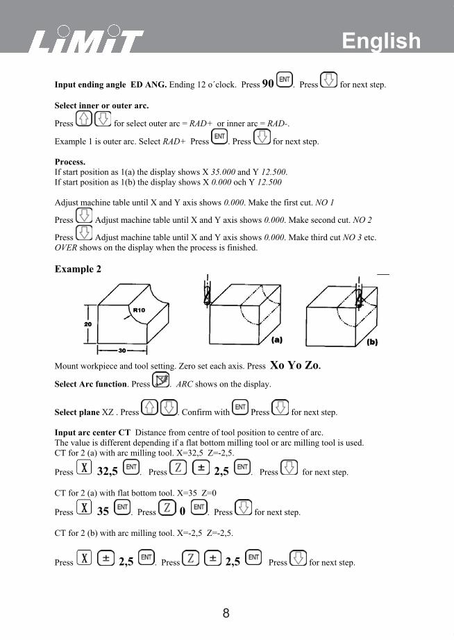
Input ending angle ED ANG. Ending 12 o´clock. Press 90 . Press for next step.
Select inner or outer arc.
Press for select outer arc = RAD+ or inner arc = RAD-.
Example 1 is outer arc. Select RAD+ Press . Press for next step.
Process.If start position as 1(a) the display shows X 35.000 and Y 12.500.If start position as 1(b) the display shows X 0.000 och Y 12.500
Adjust machine table until X and Y axis shows 0.000. Make the first cut. NO 1
Press Adjust machine table until X and Y axis shows 0.000. Make second cut. NO 2
Press Adjust machine table until X and Y axis shows 0.000. Make third cut NO 3 etc.OVER shows on the display when the process is finished.
Example 2
Mount workpiece and tool setting. Zero set each axis. Press Xo Yo Zo.
Select Arc function. Press . ARC shows on the display.
Select plane XZ . Press . Confirm with Press for next step.
Input arc center CT Distance from centre of tool position to centre of arc. The value is different depending if a flat bottom milling tool or arc milling tool is used. CT for 2 (a) with arc milling tool. X=32,5 Z=-2,5.
Press 32,5 . Press 2,5 . Press for next step.
CT for 2 (a) with flat bottom tool. X=35 Z=0
Press 35 . Press 0 . Press for next step.
CT for 2 (b) with arc milling tool. X=-2,5 Z=-2,5.
Press 2,5 . Press 2,5 Press for next step.
9
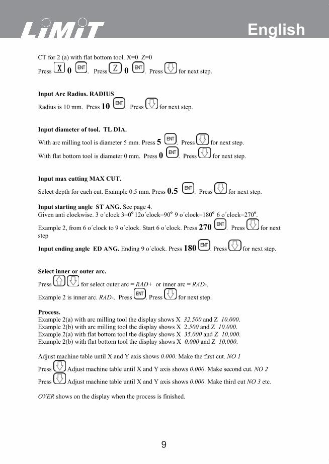
EnglishCT for 2 (a) with flat bottom tool. X=0 Z=0
Press 0 . Press 0 . Press for next step.
Input Arc Radius. RADIUS
Radius is 10 mm. Press 10 . Press for next step.
Input diameter of tool. TL DIA.
With arc milling tool is diameter 5 mm. Press 5 . Press for next step.
With flat bottom tool is diameter 0 mm. Press 0 . Press for next step.
Input max cutting MAX CUT.
Select depth for each cut. Example 0.5 mm. Press 0.5 . Press for next step.
Input starting angle ST ANG. See page 4. Given anti clockwise. 3 o´clock 3=0° 12o´clock=90° 9 o´clock=180° 6 o´clock=270°.
Example 2, from 6 o´clock to 9 o´clock. Start 6 o´clock. Press 270 . Press for next step
Input ending angle ED ANG. Ending 9 o´clock. Press 180 . Press for next step.
Select inner or outer arc.
Press for select outer arc = RAD+ or inner arc = RAD-.
Example 2 is inner arc. RAD-. Press . Press for next step.
Process.Example 2(a) with arc milling tool the display shows X 32.500 and Z 10.000.Example 2(b) with arc milling tool the display shows X 2.500 and Z 10.000.Example 2(a) with flat bottom tool the display shows X 35,000 and Z 10,000.Example 2(b) with flat bottom tool the display shows X 0,000 and Z 10,000.
Adjust machine table until X and Y axis shows 0.000. Make the first cut. NO 1
Press Adjust machine table until X and Y axis shows 0.000. Make second cut. NO 2
Press Adjust machine table until X and Y axis shows 0.000. Make third cut NO 3 etc.
OVER shows on the display when the process is finished.
10
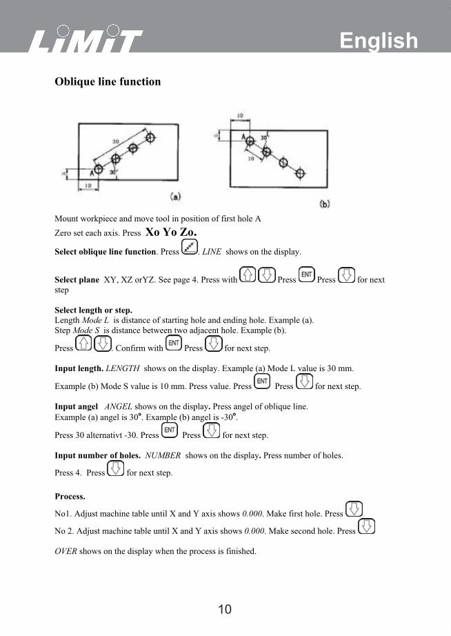
EnglishOblique line function
Mount workpiece and move tool in position of first hole A Zero set each axis. Press Xo Yo Zo.Select oblique line function. Press . LINE shows on the display.
Select plane XY, XZ orYZ. See page 4. Press with Press Press for next step
Select length or step.Length Mode L is distance of starting hole and ending hole. Example (a). Step Mode S is distance between two adjacent hole. Example (b).
Press . Confirm with Press for next step.
Input length. LENGTH shows on the display. Example (a) Mode L value is 30 mm.
Example (b) Mode S value is 10 mm. Press value. Press Press for next step.
Input angel ANGEL shows on the display. Press angel of oblique line.Example (a) angel is 30°. Example (b) angel is -30°.
Press 30 alternativt -30. Press Press for next step.
Input number of holes. NUMBER shows on the display. Press number of holes.
Press 4. Press for next step.
Process.
No1. Adjust machine table until X and Y axis shows 0.000. Make first hole. Press
No 2. Adjust machine table until X and Y axis shows 0.000. Make second hole. Press
OVER shows on the display when the process is finished.
11
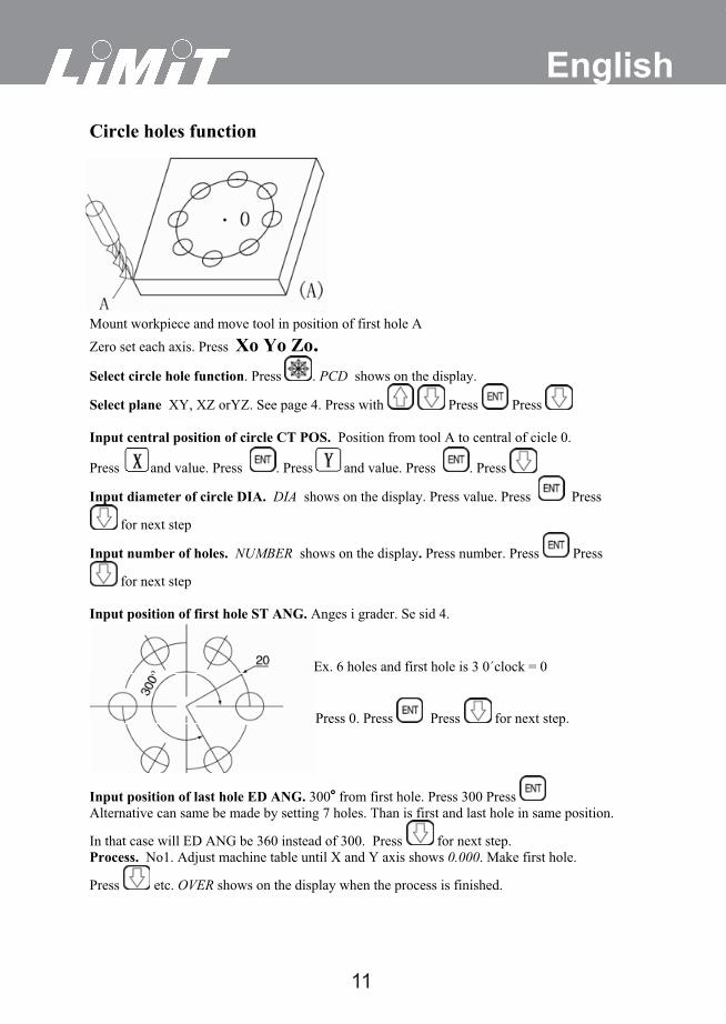
EnglishCircle holes function
Mount workpiece and move tool in position of first hole A Zero set each axis. Press Xo Yo Zo.Select circle hole function. Press . PCD shows on the display.
Select plane XY, XZ orYZ. See page 4. Press with Press Press
Input central position of circle CT POS. Position from tool A to central of cicle 0.
Press and value. Press . Press and value. Press . Press
Input diameter of circle DIA. DIA shows on the display. Press value. Press Press
for next step
Input number of holes. NUMBER shows on the display. Press number. Press Press
for next step
Input position of first hole ST ANG. Anges i grader. Se sid 4.
Ex. 6 holes and first hole is 3 0´clock = 0
Press 0. Press Press for next step.
Input position of last hole ED ANG. 300° from first hole. Press 300 Press Alternative can same be made by setting 7 holes. Than is first and last hole in same position.
In that case will ED ANG be 360 instead of 300. Press for next step. Process. No1. Adjust machine table until X and Y axis shows 0.000. Make first hole.
Press etc. OVER shows on the display when the process is finished.
12
EnglishBevel function Zero set each axis. Press Xo Yo Zo.Select bevelfunction. Press LINE shows on the display.
Select plane XY, XZ orYZ. See page 4. Press with Press Press for next step
Input diameter of tool. TL DIA. Press value . Press for next step.
Input start position. ST POT Press Press x-position. Press . Press Press z-
position. Press . Press for next step
Input end position. ED POT Press Press x-position. Press .
Press Press z-position. Press . Press for next step
Process. No1. Make first cut. Press
No2. Adjust machine table until X and Y axis shows 0.000. Make second cut. Press
No3 Adjust machine table until X and Y axis shows 0.000. Make second cut. Press
OVER shows on the display when the process is finished.
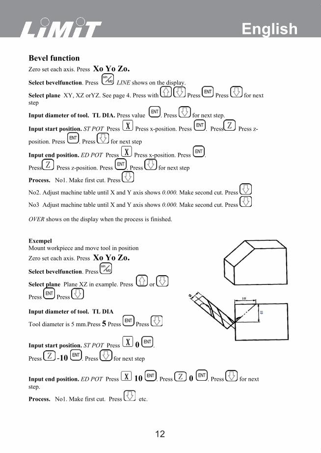
ExempelMount workpiece and move tool in positionZero set each axis. Press Xo Yo Zo.Select bevelfunction. Press
Select plane Plane XZ in example. Press or
Press Press
Input diameter of tool. TL DIA
Tool diameter is 5 mm.Press 5 Press Press
Input start position. ST POT Press 0 .
Press -10 . Press for next step
Input end position. ED POT Press 10 . Press 0 . Press for next step.
Process. No1. Make first cut. Press etc.
13
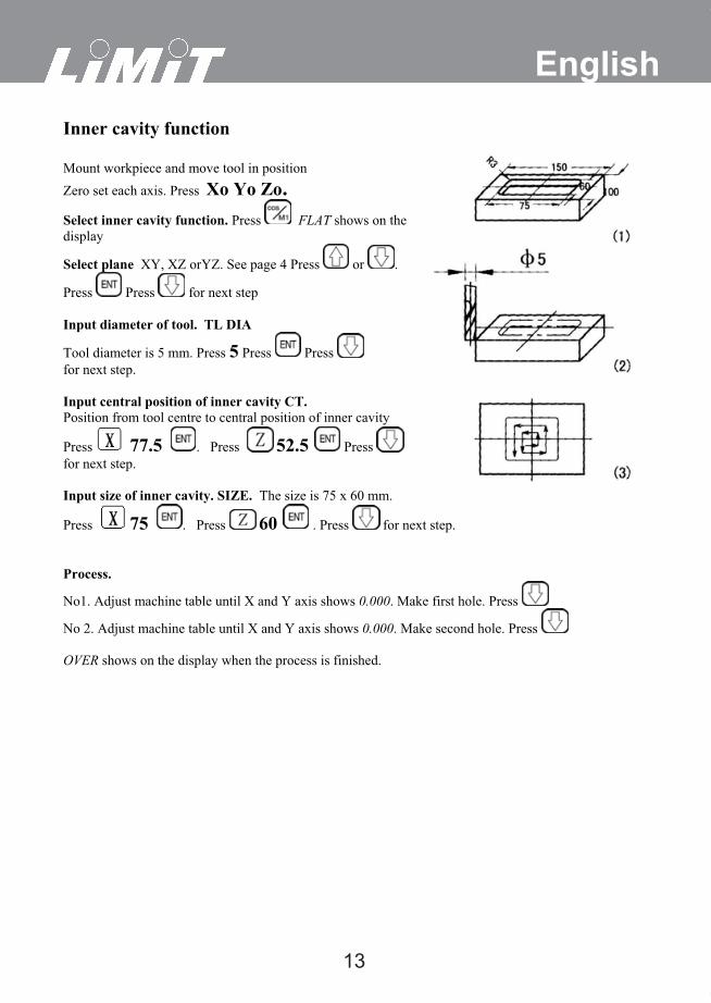
EnglishInner cavity function
Mount workpiece and move tool in positionZero set each axis. Press Xo Yo Zo.Select inner cavity function. Press FLAT shows on the display
Select plane XY, XZ orYZ. See page 4 Press or .
Press Press for next step
Input diameter of tool. TL DIA
Tool diameter is 5 mm. Press 5 Press Press for next step.
Input central position of inner cavity CT. Position from tool centre to central position of inner cavity
Press 77.5 . Press 52.5 Press for next step.
Input size of inner cavity. SIZE. The size is 75 x 60 mm.
Press 75 . Press 60 . Press for next step.
Process.
No1. Adjust machine table until X and Y axis shows 0.000. Make first hole. Press
No 2. Adjust machine table until X and Y axis shows 0.000. Make second hole. Press
OVER shows on the display when the process is finished.
14
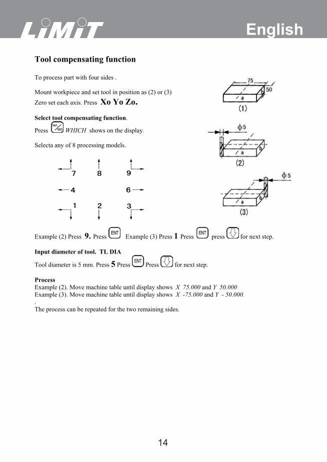
EnglishTool compensating function
To process part with four sides .
Mount workpiece and set tool in position as (2) or (3)Zero set each axis. Press Xo Yo Zo.Select tool compensating function.
Press WHICH shows on the display.
Selecta any of 8 processing models.
Example (2) Press 9. Press Example (3) Press 1 Press press for next step.
Input diameter of tool. TL DIA
Tool diameter is 5 mm. Press 5 Press Press for next step.
Process Example (2). Move machine table until display shows X 75.000 and Y 50.000Example (3). Move machine table until display shows X -75.000 and Y - 50.000. .The process can be repeated for the two remaining sides.