


![HTML [from web] epilogis a kai b lyceiou - bmichal version 1](https://static.fdocument.org/doc/165x107/55aadf8f1a28abf1378b46a0/html-from-web-epilogis-a-kai-b-lyceiou-bmichal-version-1.jpg)
γλώσσες
Σελίδες
Νομικός


D88-CHANNEL CLASS D AMPLIFIER
WITH 10-CHANNEL DSP
VERSION 1.3
V2
2
ENGLISH
TECHNICAL SPECIFICATIONS
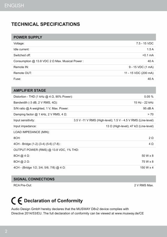
POWER SUPPLYVoltage: 7.5 - 15 VDC
Idle current: 1.5 A
Switched off: <0.1 mA
Consumption @ 13.8 VDC 2 Ω Max. Musical Power : 40 A
Remote IN: 9 - 15 VDC (1 mA)
Remote OUT: 11 - 15 VDC (200 mA)
Fuse: 40 A
AMPLIFIER STAGEDistortion - THD (1 kHz @ 4 Ω, 90% Power): 0.05 %
Bandwidth (-3 dB, 2 V RMS, 4Ω): 15 Hz - 22 kHz
S/N ratio @ A weighted, 1 V, Max. Power: 95 dB A
Damping factor @ 1 kHz, 2 V RMS, 4 Ω: > 70
Input sensitivity: 3.5 V -11 V RMS (High-level); 1.5 V - 4.5 V RMS (Line-level)
Input impedance: 13 Ω (High-level); 47 kΩ (Line-level)
LOAD IMPEDANCE (MIN):
8CH: 2 Ω
4CH - Bridge (1-2) (3-4) (5-6) (7-8) : 4 Ω
OUTPUT POWER (RMS) @ 13.8 VDC, 1% THD:
8CH @ 4 Ω: 50 W x 8
8CH @ 2 Ω: 75 W x 8
4CH - (Bridge 1/2; 3/4; 5/6; 7/8) @ 4 Ω: 150 W x 4
SIGNAL CONNECTIONSRCA Pre-Out: 2 V RMS Max.
Declaration of ConformityAudio Design GmbH hereby declares that the MUSWAY D8v2 device complies with Directive 2014/53/EU. The full declaration of conformity can be viewed at www.musway.de/CE

3
ENGLISH
DIGITAL SIGNAL PROCESSOR (32 bit Clock speed: 330 MHz)Crossover: Full / Hi Pass / Lo Pass / Band Pass
Crossover type and slope: Bessel / Butterworth / Linkwitz @ 12/18/24/30/36/42/48 dB
Crossover Frequency: 1 Hz step @ 20 Hz - 20 kHz
Phase inversion: 0° / 180°
Output Equalizer: 31-Band Parametrical Equalizer: ±12 dB
Time Alignment Distance: 0 - 692 cm
Time Alignment Delay: 0 - 20 ms
Time Alignment Step: 0,08 ms; 2,8 cm
Time Alignment Fine Set: 0,02 ms; 0,7 cm
Presets (Local Stored): 6 Presets
GENERAL REQUIREMENTSPC connections Micro USB (1.1 / 2.0 / 3.0)
Software/PC requirements: Microsoft Windows (32/64 bit):
XP, Vista, Windows 7, Windows 8, Windows 10
Graphic card min. resolution: 1024 x 768
Ambient operating temperature range: 0 - 55 °C
SIZE / WEIGHTSize without brackets (mm): 127 x 37 x 205
Net Weight (kg): 1,5
SCOPE OF DELIVERY1 x D8 DSP Amplifier1 x 1,5 m USB Cable1 x 20-pole Cable Adapter (Speaker Outputs) 1 x 20-pole Cable Adapter (High Level Inputs, REM In- and Outputs) 1 x 8-pole Cable Adapter (Pre-Amplifier In- and Outputs)1 x Owner’s Manual (English/German)1 x 40 A replacement fuse1 x 3 mm hex key
4
ENGLISH
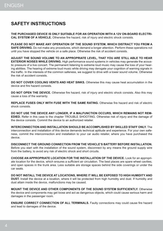
THE PURCHASED DEVICE IS ONLY SUITABLE FOR AN OPERATION WITH A 12V ON-BOARD ELECTRI-CAL SYSTEM OF A VEHICLE. Otherwise fire hazard, risk of injury and electric shock consists.
PLEASE DO NOT MAKE ANY OPERATION OF THE SOUND SYSTEM, WHICH DISTRACT YOU FROM A SAFE DRIVING. Do not make any procedures, which demand a longer attention. Perform these operations not until you have stopped the vehicle on a safe place. Otherwise the risk of accident consists.
ADJUST THE SOUND VOLUME TO AN APPROPRIATE LEVEL, THAT YOU ARE STILL ABLE TO HEAR EXTERIOR NOISES WHILE DRIVING. High performance sound systems in vehicles may generate the acous-tic pressure of a live concert. The permanent listening to extreme loud music may cause the loss of your hear-ing abilities. The hearing of extreme loud music while driving may derogate your cognition of warning signals in the traffic. In the interests of the common safeness, we suggest to drive with a lower sound volume. Otherwise the risk of accident consists.
DO NOT COVER COOLING VENTS AND HEAT SINKS. Otherwise this may cause heat accumulation in the device and fire hazard consists.
DO NOT OPEN THE DEVICE. Otherwise fire hazard, risk of injury and electric shock consists. Also this may cause a loss of the warranty.
REPLACE FUSES ONLY WITH FUSE WITH THE SAME RATING. Otherwise fire hazard and risk of electric shock consists.
DO NOT USE THE DEVICE ANY LONGER, IF A MALFUNCTION OCCURS, WHICH REMAINS NOT REM-EDIED. Refer in this case to the chapter TROUBLE SHOOTING. Otherwise risk of injury and the damage of the device consists. Commit the device to an authorized retailer.
INTERCONNECTION AND INSTALLATION SHOULD BE ACCOMPLISHED BY SKILLED STAFF ONLY. The interconnection and installation of this device demands technical aptitude and experience. For your own safe-ness, commit the interconnection and installation to your car audio retailer, where you have purchased the device.
DISCONNECT THE GROUND CONNECTION FROM THE VEHICLE’S BATTERY BEFORE INSTALLATION. Before you start with the installation of the sound system, disconnect by any means the ground supply wire from the battery, to avoid any risk of electric shock and short circuits.
CHOOSE AN APPROPRIATE LOCATION FOR THE INSTALLATION OF THE DEVICE. Look for an appropri-ate location for the device, which ensures a sufficient air circulation. The best places are spare wheel cavities, and open spaces in the trunk area. Less suitable are storage spaces behind the side coverings or under the car seats.
DO NOT INSTALL THE DEVICE AT LOCATIONS, WHERE IT WILL BE EXPOSED TO HIGH HUMIDITY AND DUST. Install the device at a location, where it will be protected from high humidity and dust. If humidity and dust attain inside the device, malfunctions may be caused.
MOUNT THE DEVICE AND OTHER COMPONENTS OF THE SOUND SYSTEM SUFFICIENTLY. Otherwise the device and components may get loose and act as dangerous objects, which could cause serious harm and damages in the passenger room.
ENSURE CORRECT CONNECTION OF ALL TERMINALS. Faulty connections may could cause fire hazard and lead to damages of the device.
SAFETY INSTRUCTIONS

5
ENGLISH
MOUNT THE DEVICE AND OTHER COMPONENTS OF THE SOUND SYSTEM SUFFICIENTLY. Otherwise the device and components may get loose and act as dangerous objects, which could cause serious harm and damages in the passenger room.
ENSURE NOT TO DAMAGE COMPONENTS, WIRES AND CABLES OF THE VEHICLE WHEN YOU DRILL THE MOUNTING HOLES. If you drill the mounting holes for the installation into the vehicle’s chassis, ensure by any means, not to damage, block or tangent the fuel pipe, the gas tank, other wires or electrical cables.
DO NOT INSTALL AUDIO CABLES AND POWER SUPPLY WIRES TOGETHER. Ensure while installation not to lead the audio cables between the head unit and the processor together with the power supply wires on the same side of the vehicle. The best is a areal separated installation in the left and right cable channel of the vehicle. Therewith a overlap of interferences on the audio signal will be avoided. This stands also for the equipped bass-remote wire, which should be installed not together with the power supply wires, but rather with the audio signal cables.
ENSURE THAT CABLES MAY NOT CAUGHT UP IN CLOSE-BY OBJECTS. Install all the wires and cables like described on the following pages, therewith these may not hinder the driver. Cables and wires which are installed close-by the steering wheel, gear lever or the brake pedal, may caught up and cause highly danger-ous situations.
DO NOT SPLICE ELECTRICAL WIRES. The electrical wires should not be bared, to provide power supply to other devices. Otherwise the load capacity of the wire may get overloaded. Use therefor a appropriate distribu-tion block. Otherwise fire hazard and risk of electric shock consists.
DO NOT USE BOLTS AND SCREW NUTS OF THE BRAKE SYSTEM AS GROUND POINT. Never use for the installation or the ground point bolts and screw-nuts of the brake system, steering system or other security-relevant components. Otherwise fire hazard consists or the driving safety will be derogated.
ENSURE NOT TO BEND OR SQUEEZE CABLES AND WIRES BY SHARP OBJECTS. Do not install cables and wires not close-by movable objects like the seat rail or may be bent or harmed by sharp and barbed edges. If you lead a wire or cable through the hole in a metal sheet, protect the insulation with a rubber grommet.
KEEP AWAY SMALL PARTS AND JACKS FROM CHILDREN. If objects like these will be swallowed, the risk of serious injuries consists. Consult promptly a medical doctor, if a child swallowed a small object.
WARRANTYThis product meets the current EU minimum warranty requirements, if purchased in countries of the EU. To en-sure your warranty policy keep your original receipt proofing the date of purchase. Any damage to the product as a result of misuse, abuse, accident, incorrect wiring, improper installation, alteration of date code or barcode labels, revolution, natural disaster, or any sneaky stuff because someone messed up, repair or alteration out side of our factory or authorized service centers and any thing else you have done that you should not have done is not covered. This warranty is limited to defective parts and specifically excludes any incidental or con-sequential damages connected therewith.
6
ENGLISH
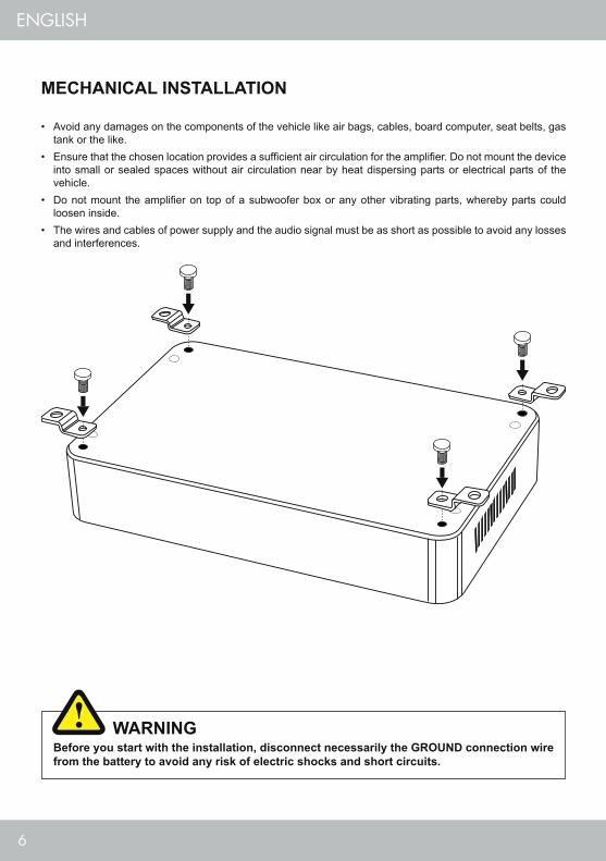
MECHANICAL INSTALLATION
Before you start with the installation, disconnect necessarily the GROUND connection wire from the battery to avoid any risk of electric shocks and short circuits.
WARNING
• Avoid any damages on the components of the vehicle like air bags, cables, board computer, seat belts, gas tank or the like.
• Ensure that the chosen location provides a sufficient air circulation for the amplifier. Do not mount the device into small or sealed spaces without air circulation near by heat dispersing parts or electrical parts of the vehicle.
• Do not mount the amplifier on top of a subwoofer box or any other vibrating parts, whereby parts could loosen inside.
• The wires and cables of power supply and the audio signal must be as short as possible to avoid any losses and interferences.
7
ENGLISH
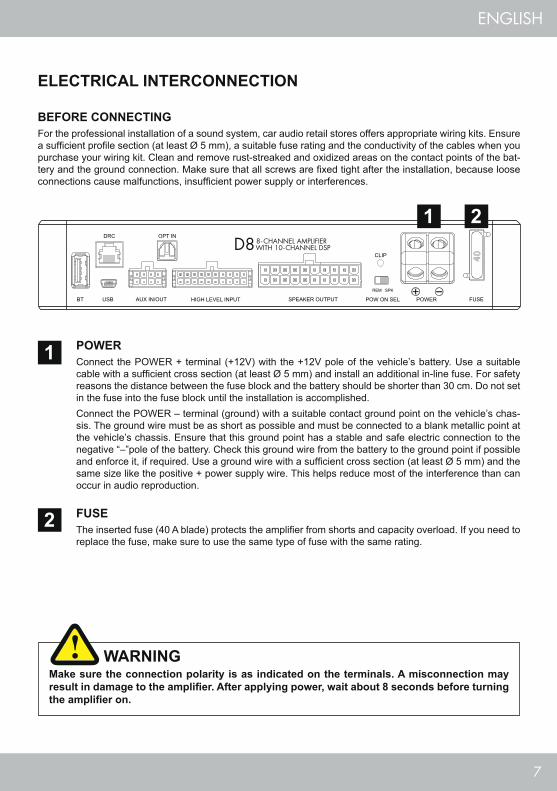
ELECTRICAL INTERCONNECTION
FUSEThe inserted fuse (40 A blade) protects the amplifier from shorts and capacity overload. If you need to replace the fuse, make sure to use the same type of fuse with the same rating.
BEFORE CONNECTINGFor the professional installation of a sound system, car audio retail stores offers appropriate wiring kits. Ensure a sufficient profile section (at least Ø 5 mm), a suitable fuse rating and the conductivity of the cables when you purchase your wiring kit. Clean and remove rust-streaked and oxidized areas on the contact points of the bat-tery and the ground connection. Make sure that all screws are fixed tight after the installation, because loose connections cause malfunctions, insufficient power supply or interferences.
POWERConnect the POWER + terminal (+12V) with the +12V pole of the vehicle’s battery. Use a suitable cable with a sufficient cross section (at least Ø 5 mm) and install an additional in-line fuse. For safety reasons the distance between the fuse block and the battery should be shorter than 30 cm. Do not set in the fuse into the fuse block until the installation is accomplished.Connect the POWER – terminal (ground) with a suitable contact ground point on the vehicle’s chas-sis. The ground wire must be as short as possible and must be connected to a blank metallic point at the vehicle’s chassis. Ensure that this ground point has a stable and safe electric connection to the negative “–”pole of the battery. Check this ground wire from the battery to the ground point if possible and enforce it, if required. Use a ground wire with a sufficient cross section (at least Ø 5 mm) and the same size like the positive + power supply wire. This helps reduce most of the interference than can occur in audio reproduction.
1
2
1
2
Make sure the connection polarity is as indicated on the terminals. A misconnection may result in damage to the amplifier. After applying power, wait about 8 seconds before turning the amplifier on.
WARNING
8
ENGLISH
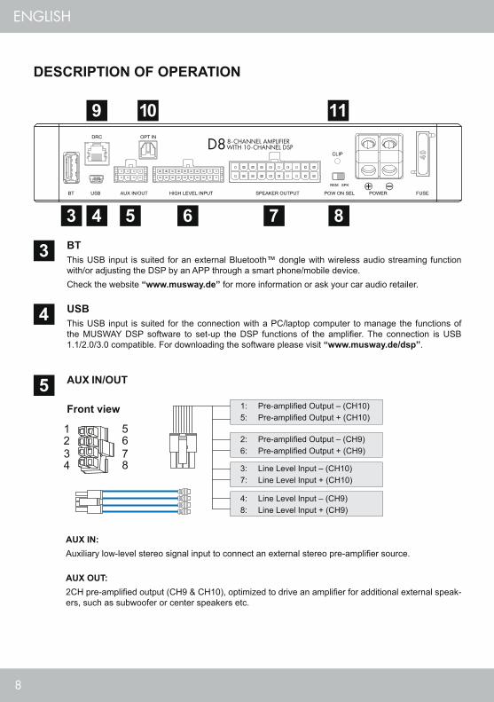
AUX IN:Auxiliary low-level stereo signal input to connect an external stereo pre-amplifier source.
AUX OUT:2CH pre-amplified output (CH9 & CH10), optimized to drive an amplifier for additional external speak-ers, such as subwoofer or center speakers etc.
USBThis USB input is suited for the connection with a PC/laptop computer to manage the functions of the MUSWAY DSP software to set-up the DSP functions of the amplifier. The connection is USB 1.1/2.0/3.0 compatible. For downloading the software please visit “www.musway.de/dsp”.
BTThis USB input is suited for an external Bluetooth™ dongle with wireless audio streaming function with/or adjusting the DSP by an APP through a smart phone/mobile device. Check the website “www.musway.de” for more information or ask your car audio retailer.
AUX IN/OUT
Front view
4
3
51: Pre-amplified Output – (CH10)5: Pre-amplified Output + (CH10)
4: Line Level Input – (CH9)8: Line Level Input + (CH9)
2: Pre-amplified Output – (CH9)6: Pre-amplified Output + (CH9)
3: Line Level Input – (CH10)7: Line Level Input + (CH10)
DESCRIPTION OF OPERATION
3 4
9 10 11
5 6 7 8
9
ENGLISH
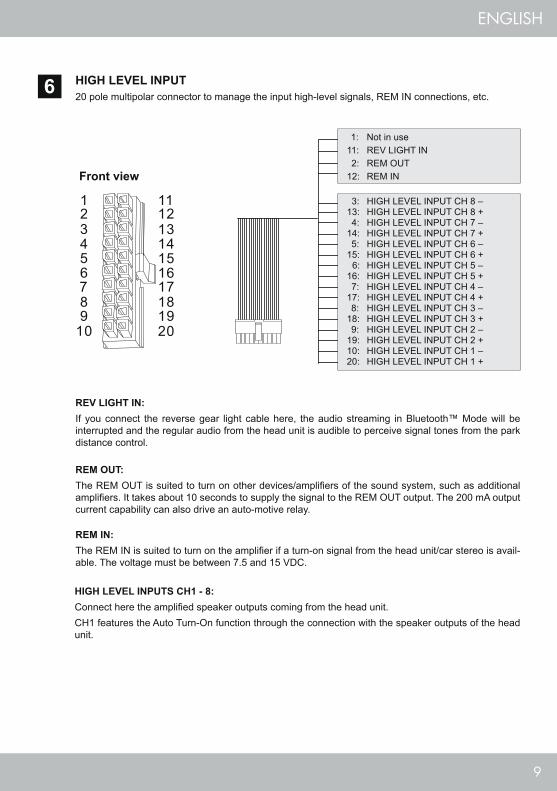
HIGH LEVEL INPUTS CH1 - 8: Connect here the amplified speaker outputs coming from the head unit.CH1 features the Auto Turn-On function through the connection with the speaker outputs of the head unit.
HIGH LEVEL INPUT20 pole multipolar connector to manage the input high-level signals, REM IN connections, etc.
REV LIGHT IN:If you connect the reverse gear light cable here, the audio streaming in Bluetooth™ Mode will be interrupted and the regular audio from the head unit is audible to perceive signal tones from the park distance control.
REM OUT:The REM OUT is suited to turn on other devices/amplifiers of the sound system, such as additional amplifiers. It takes about 10 seconds to supply the signal to the REM OUT output. The 200 mA output current capability can also drive an auto-motive relay.
REM IN:The REM IN is suited to turn on the amplifier if a turn-on signal from the head unit/car stereo is avail-able. The voltage must be between 7.5 and 15 VDC.
6
Front view
1: Not in use11: REV LIGHT IN 2: REM OUT12: REM IN
3: HIGH LEVEL INPUT CH 8 –13: HIGH LEVEL INPUT CH 8 + 4: HIGH LEVEL INPUT CH 7 –14: HIGH LEVEL INPUT CH 7 + 5: HIGH LEVEL INPUT CH 6 –15: HIGH LEVEL INPUT CH 6 + 6: HIGH LEVEL INPUT CH 5 –16: HIGH LEVEL INPUT CH 5 + 7: HIGH LEVEL INPUT CH 4 –17: HIGH LEVEL INPUT CH 4 + 8: HIGH LEVEL INPUT CH 3 –18: HIGH LEVEL INPUT CH 3 + 9: HIGH LEVEL INPUT CH 2 –19: HIGH LEVEL INPUT CH 2 +10: HIGH LEVEL INPUT CH 1 –20: HIGH LEVEL INPUT CH 1 +
10
ENGLISH
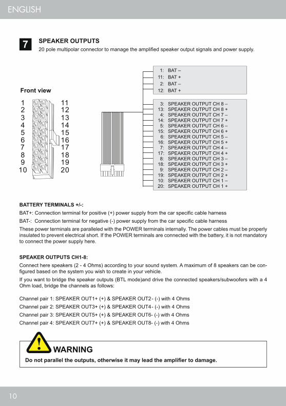
SPEAKER OUTPUTS CH1-8: Connect here speakers (2 - 4 Ohms) according to your sound system. A maximum of 8 speakers can be con-figured based on the system you wish to create in your vehicle.If you want to bridge the speaker outputs (BTL mode)and drive the connected speakers/subwoofers with a 4 Ohm load, bridge the channels as follows:
Channel pair 1: SPEAKER OUT1+ (+) & SPEAKER OUT2- (-) with 4 OhmsChannel pair 2: SPEAKER OUT3+ (+) & SPEAKER OUT4- (-) with 4 OhmsChannel pair 3: SPEAKER OUT5+ (+) & SPEAKER OUT6- (-) with 4 OhmsChannel pair 4: SPEAKER OUT7+ (+) & SPEAKER OUT8- (-) with 4 Ohms
SPEAKER OUTPUTS20 pole multipolar connector to manage the amplified speaker output signals and power supply.7
Do not parallel the outputs, otherwise it may lead the amplifier to damage.
WARNING
Front view
1: BAT –11: BAT + 2: BAT –12: BAT +
3: SPEAKER OUTPUT CH 8 –13: SPEAKER OUTPUT CH 8 + 4: SPEAKER OUTPUT CH 7 –14: SPEAKER OUTPUT CH 7 + 5: SPEAKER OUTPUT CH 6 –15: SPEAKER OUTPUT CH 6 + 6: SPEAKER OUTPUT CH 5 –16: SPEAKER OUTPUT CH 5 + 7: SPEAKER OUTPUT CH 4 –17: SPEAKER OUTPUT CH 4 + 8: SPEAKER OUTPUT CH 3 –18: SPEAKER OUTPUT CH 3 + 9: SPEAKER OUTPUT CH 2 –19: SPEAKER OUTPUT CH 2 +10: SPEAKER OUTPUT CH 1 –20: SPEAKER OUTPUT CH 1 +
BATTERY TERMINALS +/-: BAT+: Connection terminal for positive (+) power supply from the car specific cable harnessBAT-: Connection terminal for negative (-) power supply from the car specific cable harnessThese power terminals are paralleled with the POWER terminals internally. The power cables must be properly insulated to prevent electrical short. If the POWER terminals are connected with the battery, it is not mandatory to connect the power supply here.
11
ENGLISH
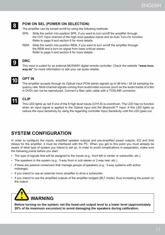
POW ON SEL (POWER ON SELECTION)The amplifier can be turned on/off by using the following methods: SPK: Slide the switch into position SPK, if you want to turn on/off the amplifier through the CH1 input channel of the high level speaker inputs and its Auto Turn-On function. Refer to page 9 and section 6 for more details.REM: Slide the switch into position REM, if you want to turn on/off the amplifier through the REM and a turn-on signal from head unit/car stereo. Refer to page 9 and section 6 for more details.
OPT INThe amplifier accepts through its Optical input PCM stereo signals up to 96 kHz / 24 bit sampling fre-quency rate. Multi-channel signals coming from audio/video sources (such as the audio tracks of a film in DVD) can not be reproduced. Connect a fiber optic cable with a TOSLINK connector.
DRCThis input is suited for an external MUSWAY digital remote controller. Check the website “www.mus-way.de” for more information or ask your car audio retailer.
8
10
9
SYSTEM CONFIGURATION
Before turning on the system, set the head-unit output level to a lower level (approximately 20% of its maximum excursion) to avoid damaging the speakers during calibration.
WARNING
In order to configure the inputs, amplified speaker outputs and pre-amplified power outputs, EQ and time delays for the amplifier, it must be interfaced with the PC. When you get to this point you must already be aware of what type of system you intend to set up. In order to avoid complications in preparation, make sure the following points before you start:• The type of signals that will be assigned to the inputs (e.g.: front left or center or subwoofer, etc.).• The speakers in the system (e.g.: 3-way front or sub stereo or 2-way rear, etc.).• If there are passive crossovers that manage groups of speakers (e.g.: 3-way systems with active
midrange).• If you intend to use an external mono amplifier to drive a subwoofer.• If you intend to use the amplified outputs of the amplifier bridged (BLT mode), thus increasing the power on
the output.
CLIPThis LED lights up red if one of the 8 high level inputs (CH1-8) is overdriven. The LED has no function when an input signal is applied to the Optical input and the Bluetooth™ input. If this LED lights up reduce the input sensitivity by using the regarding controller Input Sensitivity until the LED goes out.
11

12
ENGLISH
TYPICAL APPLICATION A
GROUND
GROUND BATTERY
FUSE HOLDER
HEAD UNIT
20: White
19: White
18: White
17: White
16: White
15: White
14: White
13: White
SUBWOOFER
Speaker Output 1+
Speaker Output 2+
Speaker Output 3+
Speaker Output 4+
Speaker Output 5+
Speaker Output 6+
Speaker Output 7+
Speaker Output 8+
Speaker Output 1-
Speaker Output 2-
Speaker Output 3-
Speaker Output 4-
Speaker Output 5-
Speaker Output 6-
Speaker Output 7-
Speaker Output 8-
10: White / Black
9: White / Black
8: White / Black
7: White / Black
6: White / Black
5: White / Black
4: White / Black
3: White / Black
@ 13.8VDC, 1% THD
STEREO MODE BRIDGE MODE
CH1 50 W @ 4 Ohms / 75 W @ 2 OhmsCH2 50 W @ 4 Ohms / 75 W @ 2 Ohms
CH1+ (+) / CH2- (-) 150 W @ 4 Ohms
CH3 50 W @ 4 Ohms / 75 W @ 2 OhmsCH4 50 W @ 4 Ohms / 75 W @ 2 Ohms
CH3+ (+) / CH4- (-) 150 W @ 4 Ohms
CH5 50 W @ 4 Ohms / 75 W @ 2 OhmsCH6 50 W @ 4 Ohms / 75 W @ 2 Ohms
CH5+ (+) / CH6- (-) 150 W @ 4 Ohms
CH7 50 W @ 4 Ohms / 75 W @ 2 OhmsCH8 50 W @ 4 Ohms / 75 W @ 2 Ohms
CH7+ (+) / CH8- (-) 150 W @ 4 Ohms
CH1-CH8 AMPLIFIED OUTPUT CHANNELS CONFIGURATION

13
ENGLISH
GROUND
GROUND BATTERY
FUSE HOLDER
TYPICAL APPLICATION B
CD PLAYER
STEREO PRE-AMPLIFIER SOURCE
SUBWOOFER
RearLeftWF
RearLeftTW
RearRight
WF
RearRight
TW
FrontLeftWF
FrontRight
WF
FrontLeftMID
FrontRightMID
FrontLeftTW
FrontRight
TW
14
ENGLISH
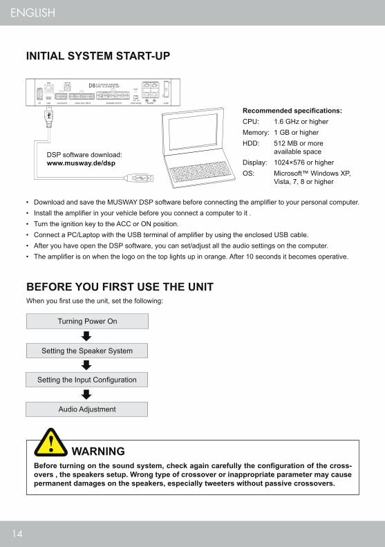
INITIAL SYSTEM START-UP
BEFORE YOU FIRST USE THE UNITWhen you first use the unit, set the following:
Turning Power On
Setting the Speaker System
Setting the Input Configuration
Audio Adjustment
• Download and save the MUSWAY DSP software before connecting the amplifier to your personal computer.• Install the amplifier in your vehicle before you connect a computer to it . • Turn the ignition key to the ACC or ON position.• Connect a PC/Laptop with the USB terminal of amplifier by using the enclosed USB cable.• After you have open the DSP software, you can set/adjust all the audio settings on the computer. • The amplifier is on when the logo on the top lights up in orange. After 10 seconds it becomes operative.
Recommended specifications:CPU: 1.6 GHz or higherMemory: 1 GB or higherHDD: 512 MB or more available spaceDisplay: 1024×576 or higherOS: Microsoft™ Windows XP, Vista, 7, 8 or higher
DSP software download: www.musway.de/dsp
Before turning on the sound system, check again carefully the configuration of the cross-overs , the speakers setup. Wrong type of crossover or inappropriate parameter may cause permanent damages on the speakers, especially tweeters without passive crossovers.
WARNING

15
ENGLISH
DSP SOFTWARE
FUNCTIONAL AND MULTILINGUALThe PC software to control the DSP provides a clear GUI with the most important functions summa-rized in one menu. As operating language several languages are available.
1SIGNAL ROUTINGWith the extensive assignment section of the inputs and outputs every conceivable signal routing is possible, which unfolds unexpected possibilities thanks to the bridgeable speaker outputs.
2PARAMETRICAL 31-BAND EQUALIZERThe equalizer section leaves nothing to be desired: graphical real-time display, adjustable Q-factor and separate full control of all channels including bypass function.
3EXTENSIVE FILTER SECTIONBesides the separately adjustable slope for high and low pass filters, different filter characteristics can be selected. Each channel can also be set separately and the output signal to AUX can be freely configured.
4
AUTOMATIC TIME ALIGNMENTEach connected loudspeaker can be set perfectly by entering the distance in centimeters to the center of the acoustic stage. After input, the correct time delay for the respective loudspeaker is automatically determined.
6
CHANNEL MIXERThis section contains the core of the software. Each channel can be processed here individually or by linking any channel pair synchronously. Among other things, the volume or the phase position can be controlled here.
5
12
34
5
6
16
ENGLISH
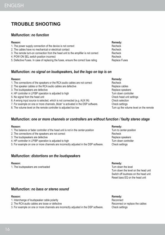
TROUBLE SHOOTING
Malfunction: no function
Reason: Remedy: 1. The power supply connection of the device is not correct Recheck2. The cables have no mechanical or electrical contact Recheck3. The remote turn-on connection from the head unit to the amplifier is not correct Recheck 4. POW ON SEL switch position incorrect Recheck5. Defective Fuses. In case of replacing the fuses, ensure the correct fuse rating Replace Fuses Malfunction: no signal on loudspeakers, but the logo on top is on
Reason: Remedy:1. The connections of the speakers or the RCA audio cables are not correct Recheck2. The speaker cables or the RCA audio cables are defective Replace cables3. The loudspeakers are defective Replace speakers4. HP controller in LP/BP operation is adjusted to high Turn down controller5. No signal from the head unit Check head unit settings6. A wrong input source is selected, which is not connected (e.g. AUX IN) Check selection7. For example on one or more channels „Mute“ is activated in the DSP software. Check settings8. The volume level on the remote controller is adjusted too low Turn up the volume level on the remote Malfunction: one or more channels or controllers are without function / faulty stereo stage
Reason: Remedy: 1. The balance or fader controller of the head unit is not in the center-position Turn to center-position 2. The connections of the speakers are not correct Recheck3. The loudspeakers are defective Replace speakers4. HP controller in LP/BP operation is adjusted to high Turn down controller5. For example on one or more channels are incorrectly adjusted in the DSP software. Check settings
Malfunction: distortions on the loudspeakers
Reason: Remedy:1. The loudspeakers are overloaded Turn down the level Turn down the level on the head unit Switch off loudness on the head unit Reset bass EQ on the head unit
Malfunction: no bass or stereo sound
Reason: Remedy: 1. Interchange of loudspeaker cable polarity Reconnect2. The RCA audio cables are loose or defective Reconnect or replace the cables3. For example on one or more channels are incorrectly adjusted in the DSP software. Check settings

17
ENGLISH
Malfunction: amplifier runs into protection mode
Reason: Remedy: 1. Short circuit on the loudspeakers or cables Reconnect2. Overheated by too low speaker impedance Choose a higher impedance Use a new speaker setup 3. Insufficient air circulation by a inappropriate mounting position of the amplifier Change the mounting position Ensure air circulation4. Overloaded by insufficient power supply (too small profile section on the power cables) Use a bigger profile section
Malfunction: hiss or white noise on the loudspeakers
Reason: Remedy:1. The level controllers in the DSP software are turned up to loud Turn down the level 2. The treble controller on the head unit is turned up Turn down the level on the head unit 3. The speaker cables or the RCA audio cables are defective Replacing the cables4. The hissing is caused by the head unit Check the head unit
18
DEUTSCH
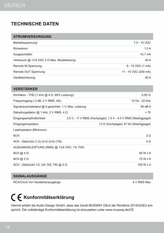
TECHNISCHE DATEN
STROMVERSORGUNGBetriebsspannung: 7,5 - 15 VDC
Ruhestrom: 1,5 A
Ausgeschaltet: <0,1 mA
Verbrauch @ 13.8 VDC 2 Ω Max. Musikleistung: 40 A
Remote IN Spannung: 9 - 15 VDC (1 mA)
Remote OUT Spannung: 11 - 15 VDC (200 mA)
Gerätesicherung: 40 A
VERSTÄRKERKlirrfaktor - THD (1 kHz @ 4 Ω, 90% Leistung): 0.05 %
Frequenzgang (-3 dB, 2 V RMS, 4Ω): 15 Hz - 22 kHz
Signalrauschabstand @ A gewichtet, 1 V, Max. Leistung: 95 dB A
Dämpfungsfaktor @ 1 kHz, 2 V RMS, 4 Ω: > 70
Eingangsempfindlichkeit: 3.5 V - 11 V RMS (Hochpegel); 1.5 V - 4.5 V RMS (Niedrigpegel)
Eingangsimpedanz: 13 Ω (Hochpegel); 47 kΩ (Niedrigpegel)
Lastimpedanz (Minimum):
8CH: 2 Ω
4CH - Gebrückt (1-2) (3-4) (5-6) (7/8) : 4 Ω
AUSGANGSLEISTUNG (RMS) @ 13,8 VDC, 1% THD:
8CH @ 4 Ω: 50 W x 8
8CH @ 2 Ω: 75 W x 8
4CH - (Gebrückt 1/2; 3/4; 5/6; 7/8) @ 4 Ω: 150 W x 4
SIGNALAUSGÄNGERCA/Cinch Vor-Verstärkerausgänge: 4 V RMS Max
KonformitätserklärungHiermit erklärt die Audio Design GmbH, dass das Gerät MUSWAY D8v2 der Richtlinie 2014/53/EU ent-spricht. Die vollständige Konformitätserklärung ist einzusehen unter www.musway.de/CE
19
DEUTSCH
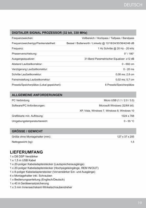
DIGITALER SIGNAL PROZESSOR (32 bit, 330 MHz)Frequenzweichen: Vollbereich / Hochpass / Tiefpass / Bandpass
Frequenzweichentyp/Flankensteilheit: Bessel / Butterworth / Linkwitz @ 12/18/24/30/36/42/48 dB
Frequenz: 1 Hz Schritte @ 20 Hz - 20 kHz
Phasenverschiebung: 0° / 180°
Ausgangsequalizer: 31-Band Parametrischer Equalizer: ±12 dB
Abstand Laufzeitkorrektur: 0 - 692 cm
Verzögerung Laufzeitkorrektur: 0 - 20 ms
Schritte Laufzeitkorrektur: 0,08 ms; 2,8 cm
Feineinstellung Laufzeitkorrektur: 0,02 ms; 0,7 cm
Presets/Speicherplätze (Lokal gepeichert): 6 Presets/Speicherplätze
ALLGEMEINE ANFORDERUNGENPC Verbindung Micro USB (1.1 / 2.0 / 3.0)
Software/PC Anforderungen: Microsoft Windows (32/64 bit):
XP, Vista, Windows 7, Windows 8, Windows 10
Grafikkarte min. Auflösung: 1024 x 768
Umgebungstemperaturbereich: 0 - 55 °C
GRÖSSE / GEWICHTGröße ohne Montagehalter (mm): 127 x 37 x 205
Nettogewicht (kg): 1,5
LIEFERUMFANG1 x D8 DSP Verstärker1 x 1,5 m USB Kabel1 x 20-poliger Kabeladapterstecker (Lautsprecherausgänge) 1 x 20-poliger Kabeladapterstecker (Hochpegeleingänge, REM IN/OUT) 1 x 8-poliger Kabeladapterstecker (Vorverstärker Ein- und Ausgänge)4 x Montagehalter inkl. Schrauben1 x Bedienungsanleitung (Englisch/Deutsch)1 x 40 A Geräteersatzsicherung1 x 3 mm Innensechskant-Winkelschraubendreher

20
DEUTSCH
DAS VON IHNEN ERWORBENE GERÄT IST NUR FÜR DEN BETRIEB AN EINEM 12-V-BORDNETZ EINES FAHRZEUGS AUSGELEGT. Andernfalls besteht Feuergefahr, die Gefahr eines elektrischen Schlages oder anderer Verletzungen.
BITTE KEINE BEDIENUNG DES SOUNDSYSTEMS AUSFÜHREN, WELCHE VOM SICHEREN LENKEN DES FAHRZEUGS ABLENKEN KÖNNTE. Führen Sie keine Bedienungen aus, die Ihre Aufmerksamkeit län-gere Zeit in Anspruch nehmen. Stoppen Sie besser das Fahrzeug an einer sicheren Stelle am Straßenrand, bevor Sie solche Bedienungen ausführen. Andernfalls besteht Unfallgefahr.
DIE LAUTSTÄRKE NUR SO HOCH EINSTELLEN, DASS SIE WÄHREND DER FAHRT NOCH AUSSENGE-RÄUSCHE WAHRNEHMEN KÖNNEN. Hochleistungsaudiosysteme in Fahrzeugen, können den Schallpegel eines “Live-Konzertes” erzeugen. Dauerhaft extrem lauter Musik ausgesetzt zu sein kann den Verlust des Hörvermögens oder Hörschäden zur Folge haben. Das Hören von lauter Musik beim Autofahren kann Ihre Wahrnehmung (Warnsignale) beeinträchtigen. Im Interesse der allgemeinen Sicherheit empfehlen wir das Mu-sikhören beim Autofahren mit geringer Lautstärke. Andernfalls besteht Unfallgefahr.
LÜFTUNGSÖFFNUNGEN UND KÜHLKÖRPER NICHT ABDECKEN. Andernfalls kann es zu einem Wärme-stau im Gerät kommen und es besteht Feuergefahr.
DAS GERÄT AUF KEINEN FALL ÖFFNEN. Andernfalls besteht Unfallgefahr, Feuergefahr oder die Gefahr eines elektrischen Schlages. Das Öffnen des Gerätes hat auch einen Garantieverlust zur Folge.
SICHERUNGEN IMMER DURCH SOLCHE MIT DER RICHTIGEN AMPEREZAHL ERSETZEN. Andernfalls besteht Feuergefahr oder die Gefahr eines elektrischen Schlages.
DAS GERÄT NICHT WEITERBENUTZEN, WENN EINE FEHLFUNKTION AUFTRITT, DIE NICHT VON IH-NEN BEHOBEN WERDEN KANN. Beachten Sie dazu den Abschnitt FEHLERBEHEBUNG. Andernfalls kann es zu Verletzungen oder Schäden am Gerät kommen. Geben Sie das Gerät zu Reparaturzwecken an einen autorisierten Händler oder den nächsten Kundendienst.
DIE INSTALLATION EINES PUFFERKONDENSATORS MIT AUSREICHENDER KAPAZIÄT WIRD EMP-FOHLEN. Hochleistungsverstärker verursachen sehr hohe Spannungsabfälle und benötigen eine sehr hohe Stromstärke bei hoher Leistung. Um das Bordnetz des Fahrzeuges nicht übermäßig zu belasten, wird die Installation eines Pufferkondensators (auch Pufferelko, Powercap oder Power Capacitor genannt) empfohlen, der parallel zum Verstärker und zur Stromquelle als Puffer fungiert. Lassen Sie sich am besten im Car Audio Fachhandel beraten.
VERKABELUNG UND EINBAU VON FACHPERSONAL AUSFÜHREN LASSEN. Die Verkabelung und der Einbau dieses Gerätes erfordern technisches Geschick und Erfahrung. Zu Ihrer eigenen Sicherheit sollten Sie Verkabelung und Einbau dem Händler überlassen, bei dem Sie das Gerät erworben haben.
VOR DER INSTALLATION DAS KABEL VOM MASSEPOL DER BATTERIE ABKLEMMEN. Bevor Sie mit der Installation des Soundsystems beginnen, trennen Sie unbedingt den Massepol der Autobatterie ab, um Kurzschlüsse und Stromschläge zu vermeiden.
WÄHLEN SIE EINEN GEEIGNETEN EINBAUORT. Suchen Sie einen geeigneten Einbauort für das Gerät, bei dem ausreichend Raum für eine kühlende Luftzirkulation vorherrscht. Am besten geeignet sind Reserverad-mulden und offene Bereiche im Kofferraum. Weniger geeignet sind Stauräume hinter der Seitenverkleidung oder Bereiche unter den Fahrzeugsitzen.
DAS GERÄT NICHT AN STELLEN EINBAUEN, AN DENEN ES HOHER FEUCHTIGKEIT ODER STAUB AUSGESETZT IST. Bauen Sie das Gerät so ein, dass es vor hoher Feuchtigkeit und Staub geschützt ist. Wenn Feuchtigkeit oder Staub in das Gerät gelangen, kann es zu Betriebsstörungen kommen. Schäden am Gerät, welche durch Feuchtigkeit hervorgerufen wurden, unter- liegen nicht der Garantie.
DAS GERÄT SOWIE ANDERE KOMPONENTEN DES SOUNDSYSTEMS AUSREICHEND BEFESTIGEN. Andernfalls könnten sich die Geräte und Komponenten während der Fahrt lösen und als gefährliche Geschos-se im Fahrgastraum Beschädigungen und Verletzungen hervorrufen.
SICHERHEITSHINWEISE
21
DEUTSCH
BEIM BOHREN VON LÖCHERN, BESTEHENDE KOMPONENTEN, LEITUNGEN UND KABEL DES FAHR-ZEUGS NICHT BESCHÄDIGEN. Wenn Sie bei der Installation Löcher in das Fahrzeugchassis bohren, achten Sie unbedingt darauf die Kraftstoffleitungen, den Benzintank, elektrische Kabel und andere Leitungen nicht zu beschädigen, zu berühren oder zu blockieren.
AUF KORREKTE ANSCHLÜSSE ACHTEN. Bei fehlerhaften Anschlüssen besteht Feuergefahr, Kurzschluss-gefahr und es kann zu Schäden am Gerät kommen.
AUDIOKABEL UND STROMKABEL SOLLTEN NICHT ZUSAMMEN VERLEGT WERDEN. Bei der Installati-on des Audiokabels zwischen dem Cinch-Ausgang des Autoradios und dem Cinch-Eingang des Verstärkers im Fahrzeug ist darauf zu achten, dass das Audio- und das Stromversorgungskabel möglichst nicht auf der selben Seite des Fahrzeugs verlegt werden. Besser ist eine räumlich getrennte Installation, im rechten und linken Ka-belschacht des Fahrzeugs. Damit wird das Überlagern von Störungen auf das Audio-Signal verringert. Dieses gilt ebenfalls für das Verbindungskabel der beiliegenden Kabel-Fernbedienung. Das Kabel sollte nicht auf der Seite der Stromversorgungsleitung verlegt werden, sondern zusammen mit den Audiokabeln.
SORGEN SIE DAFÜR, DASS SICH DIE KABEL NICHT IN GEGENSTÄNDEN IN DER NÄHE VERFANGEN. Verlegen Sie die Kabel wie auf den folgenden Seiten beschrieben, damit diese beim Fahren nicht hinderlich sind. Kabel die sich im Bereich des Lenkrads, des Schalthebels oder im Bremspedal usw. verfangen können, führen zu äußerst gefährlichen Situationen.
ELEKTRISCHE KABEL NICHT SPLEISSEN. Kabel dürfen nicht abisoliert werden, um andere Geräte mit Strom zu versorgen. Andernfalls wird die Strombelastbarkeit des Kabels überschritten, und es besteht Feu-ergefahr oder die Gefahr eines elektrischen Schlages. Verwenden Sie hierfür am besten geeignete Verteiler-blöcke.
BOLZEN UND MUTTERN DER BREMSANLAGE NICHT ALS MASSEPUNKT VERWENDEN. Verwenden Sie für den Einbau oder Masseanschluss keine Bolzen oder Muttern der Brems- bzw. Lenkanlage oder eines anderen sicherheitsrelevanten Systems. Andernfalls besteht Feuergefahr oder die Fahrsicherheit ist beein-trächtigt.
DIE KABEL SO VERLEGEN, DASS SIE NICHT GEKNICKT ODER DURCH SCHARFE KANTEN GE-QUETSCHT WERDEN. Verlegen Sie die Kabel so, dass sie sich nicht in beweglichen Teilen wie den Sitzschie-nen vefangen oder an scharfen Kanten oder spitzen Ecken beschädigt werden können. Wenn Sie ein Kabel durch eine Bohrung in einer Metallplatte führen, schützen Sie die Kabelisolierung mit einer Gummitülle vor Beschädigungen durch Metallkanten der Bohrung.
KLEINTEILE WIE SCHRAUBEN UND ANSCHLUSS-STECKER VON KINDERN FERNHALTEN. Werden solche Gegenstände verschluckt, besteht die Gefahr schwerwiegender Verletzungen. Suchen Sie unverzüg-lich einen Arzt auf, sollte ein Kind einen solchen Gegenstand verschluckt haben.
GARANTIEDieses Produkt erfüllt die aktuellen EU-Mindestgewährleistungsstandards, sofern es in Ländern der Euro-päischen Gemeinschaft erworben wurde. Um Ihren Garantieschutz aufrecht zu erhalten, bewahren Sie bitte zwecks Nachweis des Kaufdatums Ihren Originalkaufbeleg auf. Jeglicher Schaden an dem Produkt, der auf fal-sche bzw. unsachgemäße Verwendung, Unfall, falschen Anschluss, ungeeignete Installation, Veränderung der Seriennummer bzw. der Strichcodekennzeichnung, Umstürze, Naturkatastrophen oder jegliche zweckfremden Eingriffe, Reparatur oder Abänderung außerhalb unseres Kundendienstes oder autorisierter Service-Zentren, sowie alle anderen Handlungen zurückzuführen ist, die unberechtigter, weil inkompetenter Weise vorgenom-men wurden, ist von der Garantie ausgeschlossen. Diese Garantie ist auf defekte Teile beschränkt und schließt insbesondere alle zufälligen bzw. eventuellen Folgeschäden aus, die damit einhergehen.

22
DEUTSCH
MECHANISCHE INSTALLATION
Bevor Sie mit der Installation des Soundsystems beginnen, trennen Sie unbedingt den Massepol der Fahrzeugbatterie ab, um Kurzschlüsse und Stromschläge zu vermeiden.
ACHTUNG
• Achten Sie bei der Installation darauf, dass keine serienmäßig im KFZ vorhandenen Teile wie z.B. Kabel, Bordcomputer, Sicherheitsgurte, Tank oder ähnliche Teile beschädigt bzw.entfernt werden.
• Vergewissern Sie sich, dass der Verstärker am Montageort genügend Kühlung erhält. Montieren Sie das Gerät nicht in zu kleine, abgeschlossene Gehäuse ohne Luftzirkulation, in die Nähe von wärmeabstrahlende Teilen oder elektronischen Steuerungen des Fahrzeuges.
• Montieren Sie den Verstärker auf keinen Fall auf ein Bassgehäuse oder andere vibrierende Teile, dadurch können sich die Bauteile im Inneren losvibrieren und das Gerät ernsthaft beschädigen.
• Die Kabel der Stromversorgung und die Audiosignalkabel sollten bei dem Einbau so kurz als möglich gehal-ten werden, um Verluste und Störungen zu vermeiden.
23
DEUTSCH
ELEKTRISCHE ANSCHLÜSSE
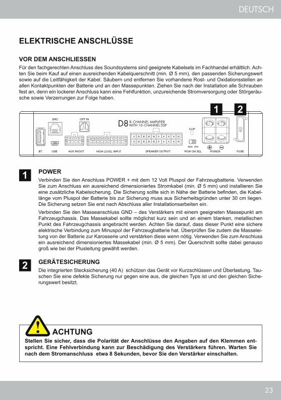
GERÄTESICHERUNGDie integrierten Stecksicherung (40 A) schützen das Gerät vor Kurzschlüssen und Überlastung. Tau-schen Sie eine defekte Sicherung nur gegen eine aus, die gleichen Typs ist und den gleichen Siche-rungswert besitzt.
VOR DEM ANSCHLIESSENFür den fachgerechten Anschluss des Soundsystems sind geeignete Kabelsets im Fachhandel erhältlich. Ach-ten Sie beim Kauf auf einen ausreichenden Kabelquerschnitt (min. Ø 5 mm), den passenden Sicherungswert sowie auf die Leitfähigkeit der Kabel. Säubern und entfernen Sie vorhandene Rost- und Oxidationsstellen an allen Kontaktpunkten der Batterie und an den Massepunkten. Ziehen Sie nach der Installation alle Schrauben fest an, denn ein lockerer Anschluss kann eine Fehlfunktion, unzureichende Stromversorgung oder Störgeräu-sche sowie Verzerrungen zur Folge haben.
POWERVerbinden Sie den Anschluss POWER + mit dem 12 Volt Pluspol der Fahrzeugbatterie. Verwenden Sie zum Anschluss ein ausreichend dimensioniertes Stromkabel (min. Ø 5 mm) und installieren Sie eine zusätzliche Kabelsicherung. Die Sicherung sollte sich in Nähe der Batterie befinden, die Kabel-länge vom Pluspol der Batterie bis zur Sicherung muss aus Sicherheitsgründen unter 30 cm liegen. Die Sicherung setzen Sie erst nach Abschluss aller Installationsarbeiten ein.Verbinden Sie den Masseanschluss GND – des Verstärkers mit einem geeigneten Massepunkt am Fahrzeugchassis. Das Massekabel sollte möglichst kurz sein und an einem blanken, metallischen Punkt des Fahrzeugchassis angebracht werden. Achten Sie darauf, dass dieser Punkt eine sichere elektrische Verbindung zum Minuspol der Fahrzeugbatterie hat. Überprüfen Sie zudem die Masselei-tung von der Batterie zur Karosserie und verstärken diese wenn nötig. Verwenden Sie zum Anschluss ein ausreichend dimensioniertes Massekabel (min. Ø 5 mm). Der Querschnitt sollte dabei genauso groß wie bei der Plusleitung gewählt werden.
2
1
Stellen Sie sicher, dass die Polarität der Anschlüsse den Angaben auf den Klemmen ent-spricht. Eine Fehlverbindung kann zur Beschädigung des Verstärkers führen. Warten Sie nach dem Stromanschluss etwa 8 Sekunden, bevor Sie den Verstärker einschalten.
ACHTUNG
1 2
24
DEUTSCH
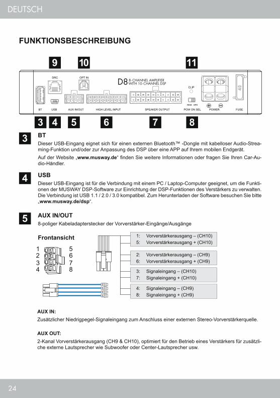
AUX IN:Zusätzlicher Niedrigpegel-Signaleingang zum Anschluss einer externen Stereo-Vorverstärkerquelle.
AUX OUT:2-Kanal Vorverstärkerausgang (CH9 & CH10), optimiert für den Betrieb eines Verstärkers für zusätzli-che externe Lautsprecher wie Subwoofer oder Center-Lautsprecher usw.
USBDieser USB-Eingang ist für die Verbindung mit einem PC / Laptop-Computer geeignet, um die Funkti-onen der MUSWAY DSP-Software zur Einrichtung der DSP-Funktionen des Verstärkers zu verwalten. Die Verbindung ist USB 1.1 / 2.0 / 3.0 kompatibel. Zum Herunterladen der Software besuchen Sie bitte „www.musway.de/dsp“.
BTDieser USB-Eingang eignet sich für einen externen Bluetooth™ -Dongle mit kabelloser Audio-Strea-ming-Funktion und/oder zur Anpassung des DSP über eine APP auf Ihrem mobilen Endgerät. Auf der Website „www.musway.de“ finden Sie weitere Informationen oder fragen Sie Ihren Car-Au-dio-Händler.
AUX IN/OUT8-poliger Kabeladapterstecker der Vorverstärker-Eingänge/Ausgänge
Frontansicht
4
3
51: Vorverstärkerausgang – (CH10)5: Vorverstärkerausgang + (CH10)
4: Signaleingang – (CH9)8: Signaleingang + (CH9)
2: Vorverstärkerausgang – (CH9)6: Vorverstärkerausgang + (CH9)
3: Signaleingang – (CH10)7: Signaleingang + (CH10)
FUNKTIONSBESCHREIBUNG
3 4
9 10 11
5 6 7 8
25
DEUTSCH
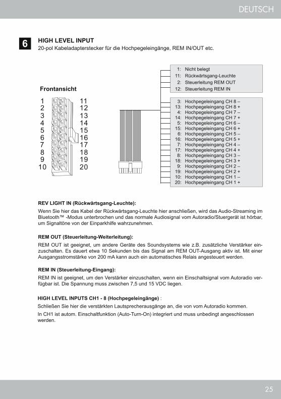
HIGH LEVEL INPUTS CH1 - 8 (Hochpegeleingänge) :Schließen Sie hier die verstärkten Lautsprecherausgänge an, die von vom Autoradio kommen. In CH1 ist autom. Einschaltfunktion (Auto-Turn-On) integriert und muss unbedingt angeschlossen werden.
HIGH LEVEL INPUT20-pol Kabeladapterstecker für die Hochpegeleingänge, REM IN/OUT etc.
REV LIGHT IN (Rückwärtsgang-Leuchte):Wenn Sie hier das Kabel der Rückwärtsgang-Leuchte hier anschließen, wird das Audio-Streaming im Bluetooth™ -Modus unterbrochen und das normale Audiosignal vom Autoradio/Stuergerät ist hörbar, um Signaltöne von der Einparkhilfe wahrzunehmen.
REM OUT (Steuerleitung-Weiterleitung):REM OUT ist geeignet, um andere Geräte des Soundsystems wie z.B. zusätzliche Verstärker ein-zuschalten. Es dauert etwa 10 Sekunden bis das Signal am REM OUT-Ausgang aktiv ist. Mit einer Ausgangsstromstärke von 200 mA kann auch ein automatisches Relais angesteuert werden.
REM IN (Steuerleitung-Eingang):REM IN ist geeignet, um den Verstärker einzuschalten, wenn ein Einschaltsignal vom Autoradio ver-fügbar ist. Die Spannung muss zwischen 7,5 und 15 VDC liegen.
6
Frontansicht
1: Nicht belegt11: Rückwärtsgang-Leuchte 2: Steuerleitung REM OUT 12: Steuerleitung REM IN
3: Hochpegeleingang CH 8 –13: Hochpegeleingang CH 8 + 4: Hochpegeleingang CH 7 –14: Hochpegeleingang CH 7 + 5: Hochpegeleingang CH 6 –15: Hochpegeleingang CH 6 + 6: Hochpegeleingang CH 5 –16: Hochpegeleingang CH 5 + 7: Hochpegeleingang CH 4 –17: Hochpegeleingang CH 4 + 8: Hochpegeleingang CH 3 –18: Hochpegeleingang CH 3 + 9: Hochpegeleingang CH 2 –19: Hochpegeleingang CH 2 +10: Hochpegeleingang CH 1 –20: Hochpegeleingang CH 1 +
26
DEUTSCH
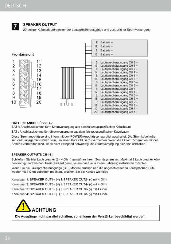
SPEAKER OUTPUTS CH1-8: Schließen Sie hier Lautsprecher (2 - 4 Ohm) gemäß an Ihrem Soundsystem an. Maximal 8 Lautsprecher kön-nen konfiguriert werden, basierend auf dem System das Sie in Ihrem Fahrzeug installieren möchten.Wenn Sie die Lautsprecherausgänge (BTL-Modus) brücken und die angeschlossenen Lautsprecher/ Sub-woofer mit 4 Ohm betreiben möchten, brücken Sie die Kanäle wie folgt:
Kanalpaar 1: SPEAKER OUT1+ (+) & SPEAKER OUT2- (-) mit 4 OhmKanalpaar 2: SPEAKER OUT3+ (+) & SPEAKER OUT4- (-) mit 4 OhmKanalpaar 3: SPEAKER OUT5+ (+) & SPEAKER OUT6- (-) mit 4 OhmKanalpaar 4: SPEAKER OUT7+ (+) & SPEAKER OUT8- (-) mit 4 Ohm
SPEAKER OUTPUT20-poliger Kabeladapterstecker der Lautsprecherausgänge und zusätzlicher Stromversorgung7
Die Ausgänge nicht parallel schalten, sonst kann der Verstärker beschädigt werden.
ACHTUNG
Frontansicht
1: Batterie –11: Batterie + 2: Batterie –12: Batterie +
3: Lautsprecherausgang CH 8 –13: Lautsprecherausgang CH 8 + 4: Lautsprecherausgang CH 7 –14: Lautsprecherausgang CH 7 + 5: Lautsprecherausgang CH 6 –15: Lautsprecherausgang CH 6 + 6: Lautsprecherausgang CH 5 –16: Lautsprecherausgang CH 5 + 7: Lautsprecherausgang CH 4 –17: Lautsprecherausgang CH 4 + 8: Lautsprecherausgang CH 3 –18: Lautsprecherausgang CH 3 + 9: Lautsprecherausgang CH 2 –19: Lautsprecherausgang CH 2 +10: Lautsprecherausgang CH 1 –20: Lautsprecherausgang CH 1 +
BATTERIEANSCHLÜSSE +/-: BAT+: Anschlussklemme für + Stromversorgung aus dem fahrzeugspezifischen KabelbaumBAT-: Anschlussklemme für - Stromversorgung aus dem fahrzeugspezifischen KabelbaumDiese Stromanschlüsse sind intern mit den POWER-Anschlüssen parallel geschaltet. Die Stromkabel müs-sen ordnungsgemäß isoliert sein, um einen Kurzschluss zu vermeiden. Wenn die POWER-Klemmen mit der Batterie verbunden sind, ist es nicht zwingend notwendig, die Stromversorgung hier anzuschließen.
27
DEUTSCH
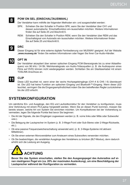
OPT INDer Verstärker akzeptiert über seinen optischen Eingang PCM-Stereosignale bis zu einer Abtastfre-quenz von 96 kHz / 24 Bit. Mehrkanalsignale von Audio-/Videoquellen (z. B. die Audiospuren eines Films auf DVD) können nicht wiedergegeben werden. Schließen Sie ein Glasfaserkabel mit einem TOSLINK-Anschluss an.
DRCDieser Eingang ist für eine externe digitale Fernbedienung von MUSWAY geeignet. Auf der Website „www.musway.de“ finden Sie weitere Informationen oder fragen Sie Ihren Car-Audio-Händler.
10
9
SYSTEMKONFIGURATION
Bevor Sie das System einschalten, stellen Sie den Ausgangspegel des Autoradios auf ei-nen niedrigeren Pegel ein (ca. 20% der maximalen Auslenkung), um eine Beschädigung der Lautsprecher während der Konfiguration zu vermeiden.
ACHTUNG
Um sämtliche Ein- und Ausgänge, den EQ und Laufzeitkorrektur für den Verstärker zu konfigurieren, muss eine Verbindung mit einem PC/Laptop hergestellt werden. Wenn Sie an diesen Punkt kommen, müssen Sie bereits wissen, welche Art von System Sie einrichten möchten. Um Komplikationen bei der Vorbereitung zu vermeiden, legen Sie folgende Punkte fest bevor Sie beginnen:• Die Art der Signale, die den Eingängen zugewiesen werden (z. B. vorne links oder Mitte oder Subwoofer
usw.).• Die Belegung der Lautsprecher im System (z. B. 3-Wege-Front oder Sub-Stereo oder 2-Wege-Rückseite,
etc.).• Ob eine passive Frequenzweichenschaltung verwendet wird, (z. B. 3-Wege-Systeme mit aktivem
Mitteltöner).• Ob Sie einen externen Monoverstärker zum Ansteuern eines Subwoofers verwenden möchten.• Ob Sie beabsichtigen, die verstärkten Ausgänge des Verstärkers zu brücken (BLT-Modus), denn dadurch
erhöht sich die Leistung am Ausgang.
POW ON SEL (EINSCHALTAUSWAHL)Der Verstärker kann mithilfe der folgenden Methoden ein- und ausgeschaltet werden:SPK: Schieben Sie den Schalter in Position SPK, wenn Sie den Verstärker über CH1 und dessen automatische Einschaltfunktion ein-/ausschalten möchten. Weitere Informationen finden Sie auf Seite 25 und Abschnitt 6.REM: Schieben Sie den Schalter in Position REM, wenn Sie den Verstärker über REM und das Einschaltsignal vom Autoradio ein-/ausschalten möchten. Weitere Informationen finden Sie auf Seite 25 und Abschnitt 6.
8
CLIPDiese LED leuchtet rot, wenn einer der sechs Hochpegeleingänge (CH1-4 & CH5 / 6) übersteuert ist. Die LED hat keine Funktion am optischen Eingang und Bluetooth™-Eingang. Wenn diese LED leuchtet, verringern Sie die Eingangsempfindlichkeit indem Sie den betreffenden Regler zurückdrehen bis die LED erlischt.
11
28
DEUTSCH
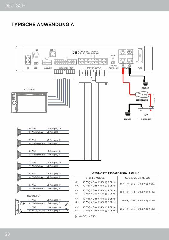
TYPISCHE ANWENDUNG A
MASSE
MASSE BATTERIE
SICHERUNG
AUTORADIO
20: Weiß
19: Weiß
18: Weiß
17: Weiß
16: Weiß
15: Weiß
14: Weiß
13: Weiß
SUBWOOFER
LS-Ausgang 1+
LS-Ausgang 2+
LS-Ausgang 3+
LS-Ausgang 4+
LS-Ausgang 5+
LS-Ausgang 6+
LS-Ausgang 7+
LS-Ausgang 8+
LS-Ausgang 1-
LS-Ausgang 2-
LS-Ausgang 3-
LS-Ausgang 4-
LS-Ausgang 5-
LS-Ausgang 6-
LS-Ausgang 7-
LS-Ausgang 8-
10: Weiß/Schwarz
9: Weiß/Schwarz
8: Weiß/Schwarz
7: Weiß/Schwarz
6: Weiß/Schwarz
5: Weiß/Schwarz
4: Weiß/Schwarz
3: Weiß/Schwarz
@ 13.8VDC, 1% THD
STEREO MODUS GEBRÜCKTER MODUS
CH1 50 W @ 4 Ohm / 75 W @ 2 OhmsCH2 50 W @ 4 Ohm / 75 W @ 2 Ohms
CH1+ (+) / CH2- (-) 150 W @ 4 Ohm
CH3 50 W @ 4 Ohm / 75 W @ 2 OhmsCH4 50 W @ 4 Ohm / 75 W @ 2 Ohms
CH3+ (+) / CH4- (-) 150 W @ 4 Ohm
CH5 50 W @ 4 Ohm / 75 W @ 2 OhmsCH6 50 W @ 4 Ohm / 75 W @ 2 Ohms
CH5+ (+) / CH6- (-) 150 W @ 4 Ohm
CH7 50 W @ 4 Ohm / 75 W @ 2 OhmsCH8 50 W @ 4 Ohm / 75 W @ 2 Ohms
CH7+ (+) / CH8- (-) 150 W @ 4 Ohm
VERSTÄRKTE AUSGANGSKANÄLE CH1 - 8

29
DEUTSCH
TYPISCHE ANWENDUNG B
MASSE
MASSE BATTERIE
SICHERUNG
CD-PLAYER
VOR-VERSTÄRKERSTEREO-QUELLE
SUBWOOFER
RearLeftWF
RearLeftTW
RearRight
WF
RearRight
TW
FrontLeftWF
FrontRight
WF
FrontLeftMID
FrontRightMID
FrontLeftTW
FrontRight
TW
30
DEUTSCH
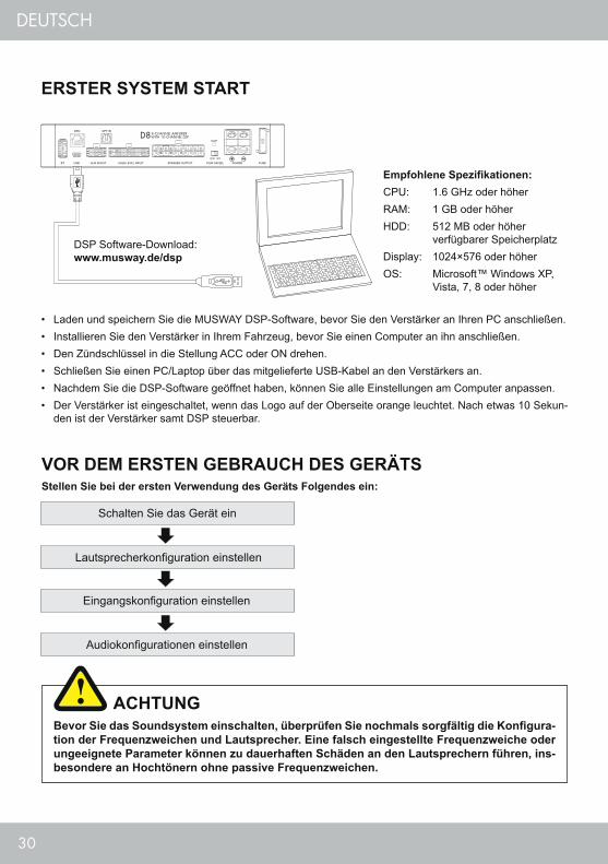
ERSTER SYSTEM START
VOR DEM ERSTEN GEBRAUCH DES GERÄTSStellen Sie bei der ersten Verwendung des Geräts Folgendes ein:
Schalten Sie das Gerät ein
Lautsprecherkonfiguration einstellen
Eingangskonfiguration einstellen
Audiokonfigurationen einstellen
Bevor Sie das Soundsystem einschalten, überprüfen Sie nochmals sorgfältig die Konfigura-tion der Frequenzweichen und Lautsprecher. Eine falsch eingestellte Frequenzweiche oder ungeeignete Parameter können zu dauerhaften Schäden an den Lautsprechern führen, ins-besondere an Hochtönern ohne passive Frequenzweichen.
ACHTUNG
• Laden und speichern Sie die MUSWAY DSP-Software, bevor Sie den Verstärker an Ihren PC anschließen.• Installieren Sie den Verstärker in Ihrem Fahrzeug, bevor Sie einen Computer an ihn anschließen.• Den Zündschlüssel in die Stellung ACC oder ON drehen.• Schließen Sie einen PC/Laptop über das mitgelieferte USB-Kabel an den Verstärkers an.• Nachdem Sie die DSP-Software geöffnet haben, können Sie alle Einstellungen am Computer anpassen.• Der Verstärker ist eingeschaltet, wenn das Logo auf der Oberseite orange leuchtet. Nach etwas 10 Sekun-
den ist der Verstärker samt DSP steuerbar.
Empfohlene Spezifikationen:CPU: 1.6 GHz oder höherRAM: 1 GB oder höherHDD: 512 MB oder höher verfügbarer SpeicherplatzDisplay: 1024×576 oder höherOS: Microsoft™ Windows XP, Vista, 7, 8 oder höher
DSP Software-Download: www.musway.de/dsp

31
DEUTSCH
DSP SOFTWARE
FUNKTIONELL UND MULTILINGUALDie PC-Software zur Steuerung des DSP bietet eine übersichtliche GUI mit der die wichtigsten Funk-tionen in einem Menü zusammengefasst sind. Als Bediensprache sind mehrere Sprachen verfügbar.
1EIN- UND AUSGANGSBELEGUNGMit der umfangreichen Belegung der Ein- und Ausgänge ist jedes erdenkliche Signalrouting möglich, was dank der brückbaren Lautsprecherausgänge ungeahnte Möglichkeiten entfaltet.
2
PARAMETRISCHER 31-BAND EQUALIZERDie EQ-Sektion lässt keine Wünsche offen: grafische Echtzeitdarstellung, einstellbarer Q-Wert sowie eine separate volle Kontrolle über alle Kanäle samt Bypass-Funktion.
3UMFANGREICHE FILTERSEKTIONNeben der für Hoch- & Tiefpassfilter getrennt einstellbaren Flankensteilheit sind zudem verschiedenen Charakteris-tiken auswählbar. Jeder Kanal ist separat einstellbar und das Ausgangssignal an AUX kann frei konfiguriert werden.
4
AUTOMATISCHE LAUFZEITBERECHNUNGHier kann jeder angeschlossene Lautsprecher durch Eingabe der Entfernung in Zentimetern zur akusti-schen Bühnenmitte perfekt eingestellt werden. Nach Eingabe wird automatisch die korrekte Laufzeitverzö-gerung für den jeweiligen Lautsprecher ermittelt.
6
KANALMIXERHier kann jeder Kanal individuell oder per Verlinkung ein beliebiges Kanalpaar synchron bearbeitet werden. Hier kann auch die Lautstärke oder die Phasenlage gesteuert werden.
5
12
34
5
6

32
DEUTSCH
FEHLERBEHEBUNG
Fehler: keine Funktion
Ursache: Lösung: 1. Die Stromversorgungskabel sind nicht korrekt angeschlossen. Erneute Überprüfung2. Die Kabel haben keinen elektrischen und mechanischen Kontakt. Erneute Überprüfung3. Die Remote-Steuerleitung des Autoradios ist nicht korrekt am Verstärker angeschlossen. Erneute Überprüfung4. POW ON SEL Schalterstellung nicht korrekt Erneute Überprüfung5. Sicherungen defekt. Achten Sie beim Austausch auf den korrekten Wert der Sicherungen. Sicherungen ersetzen Fehler: kein Ton aus Lautsprecher, aber das Logo auf dem Verstärker leuchtet
Ursache: Lösung:1. Die Lautsprecherkabel oder Signalkabel sind nicht korrekt angeschlossen. Erneute Überprüfung2. Die Lautsprecherkabel oder Signalkabel sind defekt. Kabel ersetzen3. Die Lautsprecher sind defekt. Lautsprecher ersetzen4. HP Regler in Betriebsart LP/BP zu hoch eingestellt. Regler herunterdrehen5. Kein Signal vom Autoradio. Autoradio-Einstellungen überprüfen6. Falsche Audioquelle ausgewählt, die nicht angeschlossen ist (z.B. AUX IN) Auswahl überprüfen7. In der DSP-Software ist z.B. „Mute“ für einen oder alle Kanäle aktiviert. Einstellungen überprüfen8. Lautstärke an der Fernbedienung ist zu niedrig eingestellt. Volume-Regler höher drehen Fehler: Ein bzw. mehrere Kanäle oder Regler sind ohne Funktion / fehlerhaftes Stereobild
Ursache: Lösung: 1. Der Balance- bzw. Fader-Regler am Autoradio ist nicht in der Mittel-Position. Auf Nullwert stellen2. Ein Kabel an Lautsprecher oder Verstärker hat sich gelöst. Erneute Überprüfung3. Die Lautsprecher sind defekt. Lautsprecher ersetzen4. HP Regler in Betriebsart LP/BP zu hoch eingestellt. Regler herunterdrehen5. In der DSP-Software ist ein oder mehrere Kanäle falsch eingestellt. Einstellungen überprüfen
Fehler: Verzerrungen aus Lautsprecher
Ursache: Lösung:1. Die Lautsprecher sind überlastet. Pegel niedriger einstellen Pegel am Autoradio niedriger einstellen Loudness am Audioradio abschalten Bass EQ am Steuergerät neu einstellen
Fehler: Keine Bässe bzw. kein Stereo-Sound
Ursache: Lösung:1. Beim Anschluss sind an den Lautsprechern ist die Polarität vertauscht worden. Erneuter anschließen2. Die Cinchkabel sind lose, falsch angeschlossen oder beschädigt/defekt. Erneuter anschließen oder ersetzen3. In der DSP-Software ist ein oder mehrere Kanäle falsch eingestellt. Einstellungen überprüfen
33
DEUTSCH
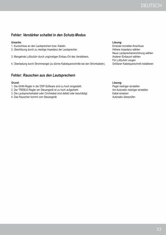
Fehler: Verstärker schaltet in den Schutz-Modus
Ursache: Lösung:1. Kurzschluss an den Lautsprechern bzw. Kabeln. Erneuter korrekter Anschluss2. Überhitzung durch zu niedrige Impedanz der Lautsprecher. Höhere Impedanz wählen Neue Lautsprecheranordnung wählen3. Mangelnde Luftzufuhr durch ungünstigen Einbau-Ort des Verstärkers. Anderer Einbauort wählen Für Luftzufuhr sorgen4. Überlastung durch Strommangel (zu dünne Kabelquerschnitte bei den Stromkabeln). Größerer Kabelquerschnitt installieren
Fehler: Rauschen aus den Lautsprechern
Grund: Lösung:1. Die GAIN-Regler in der DSP-Software sind zu hoch eingestellt. Pegel niedriger einstellen2. Der TREBLE-Regler am Steuergerät ist zu hoch aufgedreht. Am Autoradio niedriger einstellen3. Die Lautsprecherkabel oder Cinchkabel sind defekt oder beschädigt. Kabel ersetzen4. Das Rauschen kommt vom Steuergerät. Autoradio überprüfen

34
DEUTSCH

35
DEUTSCH

MUSWAY is a brand of Audio Design GmbHAm Breilingsweg 3 · D-76709 Kronau
Tel. +49 7253 - 9465-0 · Fax +49 7253 - 946510© Audio Design GmbH, All Rights Reserved
www.musway.de
Top Related