


γλώσσες
Σελίδες
Νομικός

Polarimetric Calibration of theIngara Bistatic SAR
Alvin Goh,1,2 Mark Preiss,1 Nick Stacy,1 Doug Gray2
1. Imaging Radar Systems GroupDefence Science and Technology Organisation
2. School of Electrical & Electronic EngineeringUniversity of Adelaide
2
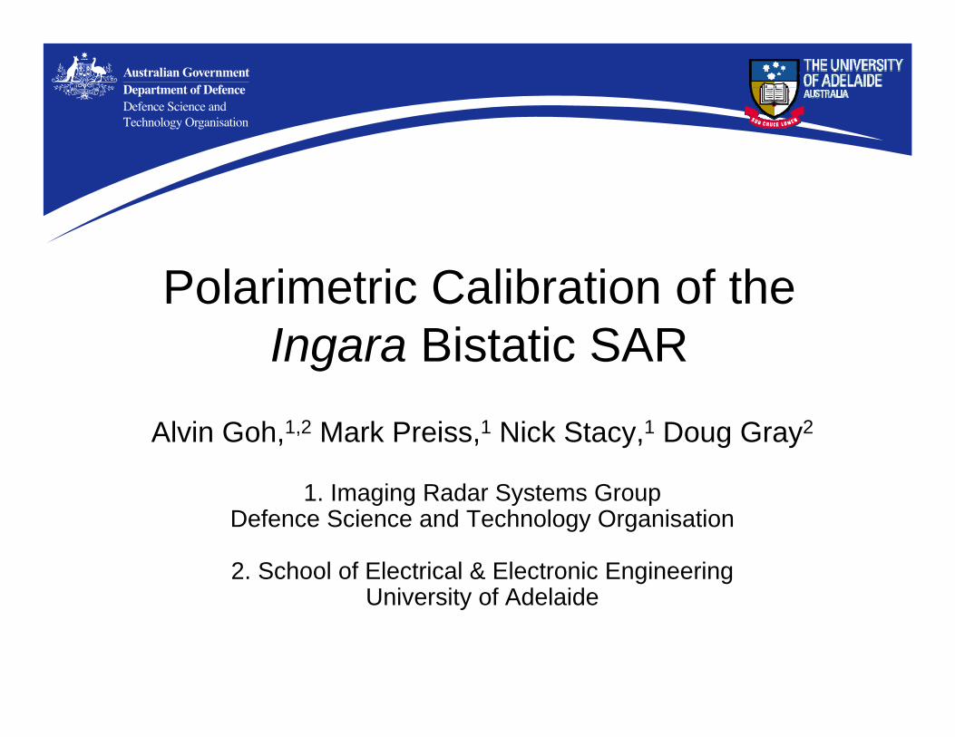
Bistatic SAR experiments
RadiusAltitude
Orbit
Imagedscene
AirborneTx & Rx
Tx-to-Rx azimuth separation angle φ
Ground-basedRx
x
y
zReciprocity ⇒ shv = svh in monostatic but not bistatic: potentially more information in bistatic measurements
Supplement Ingara X-band full-pol. airborne SAR with stationary full-pol. ground-based receiver on 15 metre high tower
Synch. using GPS 1PPS; operate at fixed 650 Hz PRF
Operate in circular spotlight-SAR mode:orbit radii 3 – 6 km; altitudes 1000 – 3600 m; incidence angles 53° – 82°
Simultaneously collect 600 MHz bandwidth full-pol. monostatic and bistatic data over wide variety of angles
Airborne Tx & Rx antenna
Ground-basedRx-only antenna
Beechcraft 1900C
3
Polarimetricmeasurement model
Y = rvv tvv
O = R S T + N
o = P s + n
P = Y M A K
1zuuzv1uvuwwz1zvwwv1
M = A =
10000α000010000α
K =
10000k0000k0000k2
O = ovvovh
ohvohhR = rvvrvh
rhvrhhS = svvsvh
shvshhT = tvvtvh
thvthhN = nvvnvh
nhvnhh
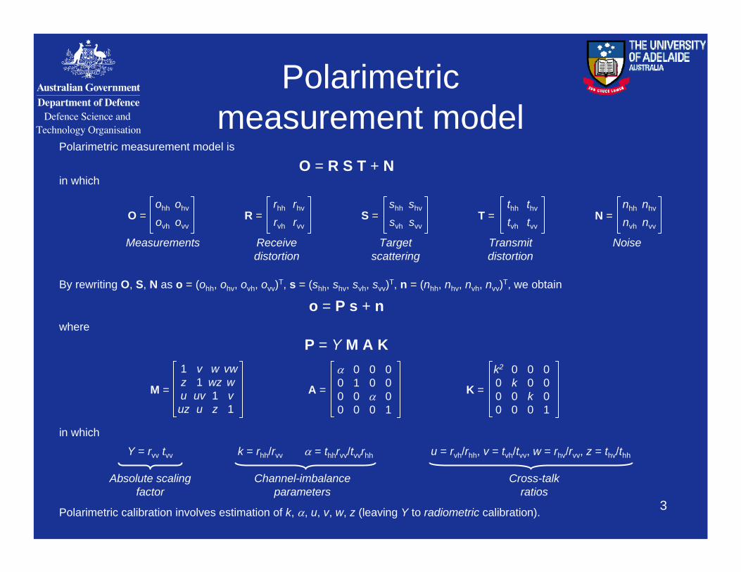
Polarimetric measurement model is
in which
By rewriting O, S, N as o = (ohh, ohv, ovh, ovv)T, s = (shh, shv, svh, svv)T, n = (nhh, nhv, nvh, nvv)T, we obtain
where
Measurements Receive distortion
Transmit distortion
Target scattering
Noise
α = thhrvv/tvvrhh u = rvh/rhh, v = tvh/tvv, w = rhv/rvv, z = thv/thhk = rhh/rvv
Cross-talkratios
Channel-imbalance parameters
Absolute scaling factor
Polarimetric calibration involves estimation of k, α, u, v, w, z (leaving Y to radiometric calibration).
in which
4
Distributed-targetmethods 1
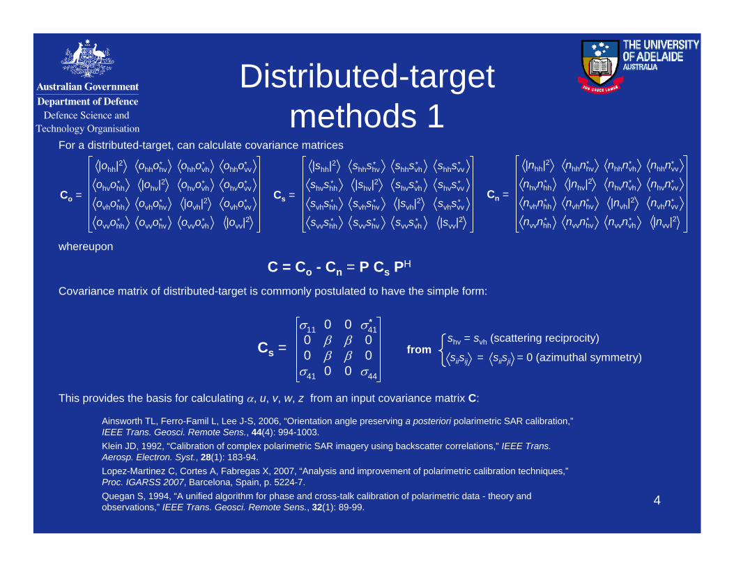
For a distributed-target, can calculate covariance matrices
Co =
|ohh|2
|ohv|2
|ovh|2
|ovv|2
ohhohv* ohhovh
* ohhovv*
ohvovh* ohvovv
*
ovhovv*
ohvohh*
ovhohh*
ovvohh*
ovhohv*
ovvohv* ovvovh
*
Cn =
|nhh|2
|nhv|2
|nvh|2
|nvv|2
nhhnhv* nhhnvh
* nhhnvv*
nhvnvh* nhvnvv
*
nvhnvv*
nhvnhh*
nvhnhh*
nvvnhh*
nvhnhv*
nvvnhv* nvvnvh
*
whereupon
C = Co - Cn = P Cs PH
Cs =
|shh|2
|shv|2
|svh|2
|svv|2
shhshv* shhsvh
* shhsvv*
shvsvh* shvsvv
*
svhsvv*
shvshh*
svhshh*
svvshh*
svhshv*
svvshv* svvsvh
*
Covariance matrix of distributed-target is commonly postulated to have the simple form:
Cs =
This provides the basis for calculating α, u, v, w, z from an input covariance matrix C:
fromshv = svh (scattering reciprocity)
siisij = siisji = 0 (azimuthal symmetry)σ4400σ41
0ββ00ββ0σ4100σ11
*
Ainsworth TL, Ferro-Famil L, Lee J-S, 2006, “Orientation angle preserving a posteriori polarimetric SAR calibration,”IEEE Trans. Geosci. Remote Sens., 44(4): 994-1003.Klein JD, 1992, “Calibration of complex polarimetric SAR imagery using backscatter correlations,” IEEE Trans. Aerosp. Electron. Syst., 28(1): 183-94.Lopez-Martinez C, Cortes A, Fabregas X, 2007, “Analysis and improvement of polarimetric calibration techniques,”Proc. IGARSS 2007, Barcelona, Spain, p. 5224-7.Quegan S, 1994, “A unified algorithm for phase and cross-talk calibration of polarimetric data - theory and observations,” IEEE Trans. Geosci. Remote Sens., 32(1): 89-99.
5
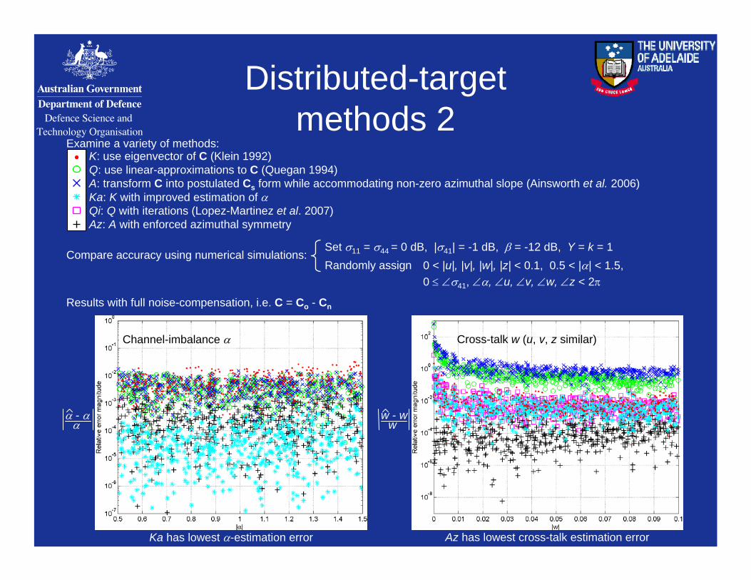
Distributed-targetmethods 2
K: use eigenvector of C (Klein 1992)Q: use linear-approximations to C (Quegan 1994)A: transform C into postulated Cs form while accommodating non-zero azimuthal slope (Ainsworth et al. 2006)Ka: K with improved estimation of αQi: Q with iterations (Lopez-Martinez et al. 2007)Az: A with enforced azimuthal symmetry
Compare accuracy using numerical simulations:
Examine a variety of methods:
Results with full noise-compensation, i.e. C = Co - Cn
Ka has lowest α-estimation error Az has lowest cross-talk estimation error
0 < |u|, |v|, |w|, |z| < 0.1, 0.5 < |α| < 1.5,0 ≤ ∠σ41, ∠α, ∠u, ∠v, ∠w, ∠z < 2π
Set σ11 = σ44 = 0 dB, |σ41| = -1 dB, β = -12 dB, Y = k = 1Randomly assign
α - αα
w - ww
Channel-imbalance α Cross-talk w (u, v, z similar)
6
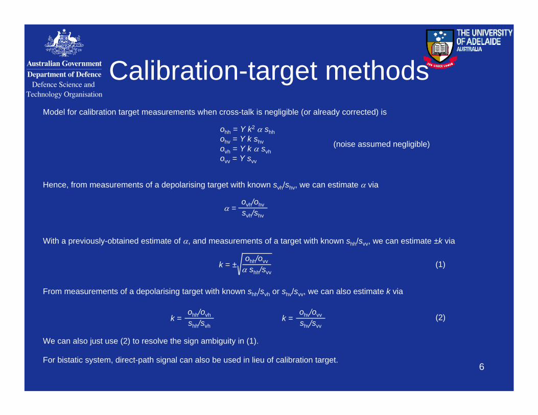
Calibration-target methodsModel for calibration target measurements when cross-talk is negligible (or already corrected) is
ohh = Y k2 α shhohv = Y k shvovh = Y k α svhovv = Y svv
α = ovh/ohvsvh/shv
k = ±ohh/ovv
α shh/svv
k =ohv/ovvshv/svv
k =ohh/ovhshh/svh
Hence, from measurements of a depolarising target with known svh/shv, we can estimate α via
With a previously-obtained estimate of α, and measurements of a target with known shh/svv, we can estimate ±k via
From measurements of a depolarising target with known shh/svh or shv/svv, we can also estimate k via
We can also just use (2) to resolve the sign ambiguity in (1).
(2)
(1)
(noise assumed negligible)
For bistatic system, direct-path signal can also be used in lieu of calibration target.
7
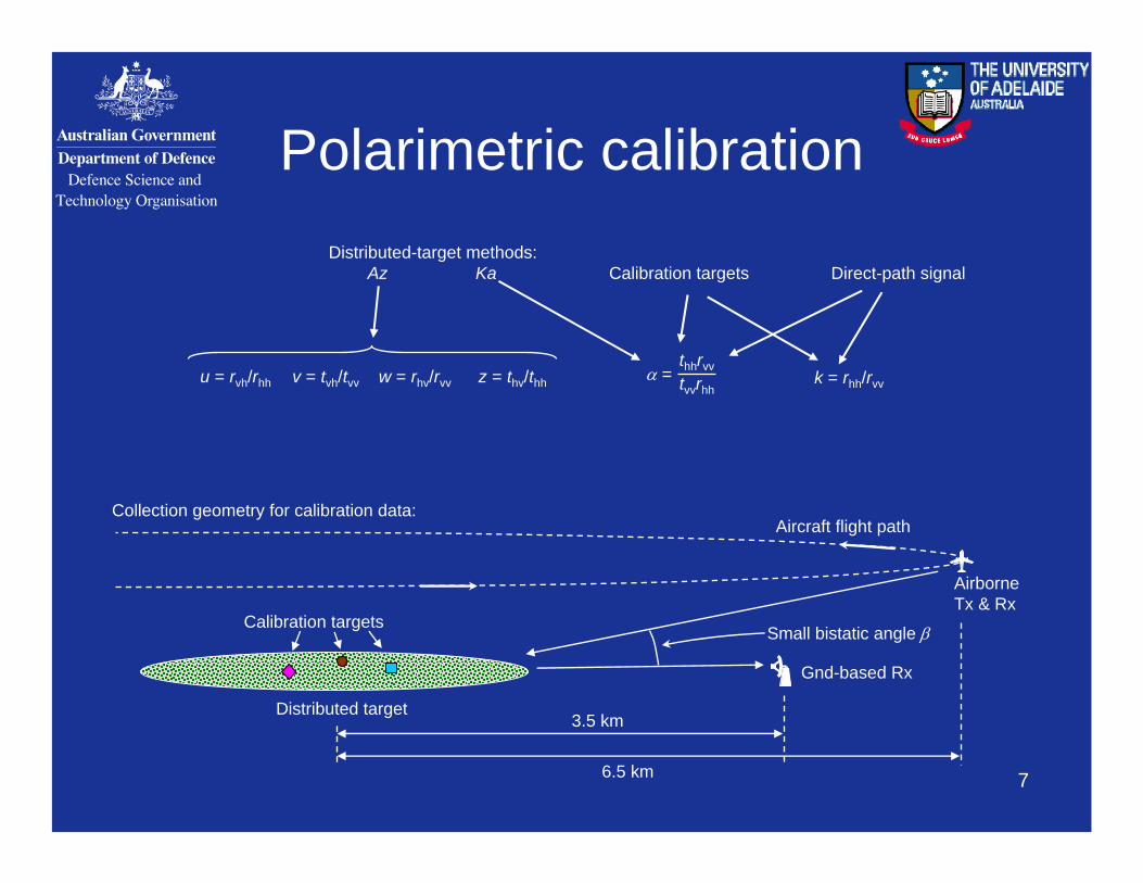
Polarimetric calibration
k = rhh/rvv
Distributed-target methods:Az Ka Direct-path signal
u = rvh/rhh v = tvh/tvv w = rhv/rvv z = thv/thh α = tvvrhh
thhrvv
Airborne Tx & Rx
Distributed target
Small bistatic angle β
Aircraft flight path
Gnd-based Rx
Calibration targets
3.5 km
6.5 km
Collection geometry for calibration data:
Calibration targets
8
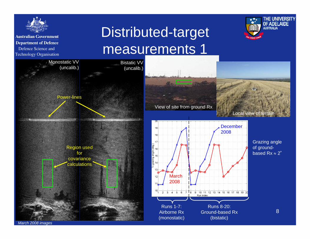
Distributed-targetmeasurements 1
Runs 1-7:Airborne Rx (monostatic)
Runs 8-20:Ground-based Rx
(bistatic)
March 2008
December 2008
Region used for
covariance calculations
Monostatic VV (uncalib.)
Bistatic VV (uncalib.)
Grazing angle of ground-based Rx ≈ 2˚
View of site from ground RxLocal view of terrain
March 2008 images
Power-lines
9
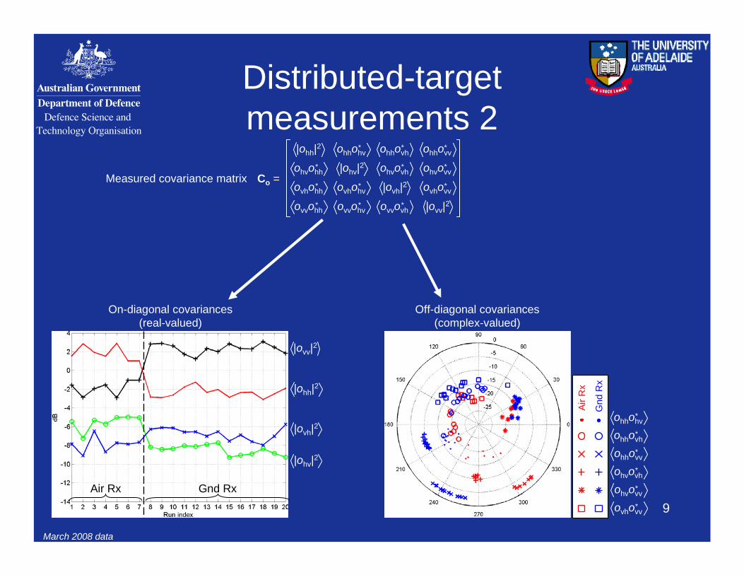
Distributed-targetmeasurements 2
On-diagonal covariances(real-valued)
Co =
|ohh|2
|ohv|2
|ovh|2
|ovv|2
ohhohv* ohhovh
* ohhovv*
ohvovh* ohvovv
*
ovhovv*
ohvohh*
ovhohh*
ovvohh*
ovhohv*
ovvohv* ovvovh
*
Measured covariance matrix
Off-diagonal covariances(complex-valued)
|ovv|2
|ohh|2
|ohv|2
|ovh|2
Air Rx Gnd Rx
ohhohv*
ohhovh*
ovhovv*
ohvovv*
ohhovv*
ohvovh*
Air
Rx
Gnd
Rx
March 2008 data
10
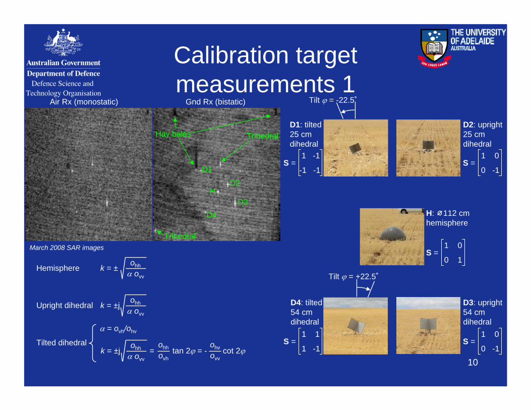
Calibration targetmeasurements 1
D2
D3D4
D1
H
D4: tilted54 cm dihedral
Tilt ϕ = +22.5˚
Tilt ϕ = -22.5˚
D3: upright54 cm dihedral
D2: upright25 cm dihedral
D1: tilted25 cm dihedral
S =1 -1
-1 -1S =
1 0
0 -1
S =1 0
0 -1S =
1 1
1 -1
H: 112 cm hemisphere
S =1 0
0 1
Hay bales Trihedral
Trihedral
Air Rx (monostatic) Gnd Rx (bistatic)
March 2008 SAR images
α = ovh/ohv
Hemisphere
k = ±j = tan 2ϕ = - cot 2ϕohh
α ovv
k = ±ohh
α ovv
Upright dihedral
Tilted dihedral
k = ±johh
α ovv
ohhovh
ohvovv
11
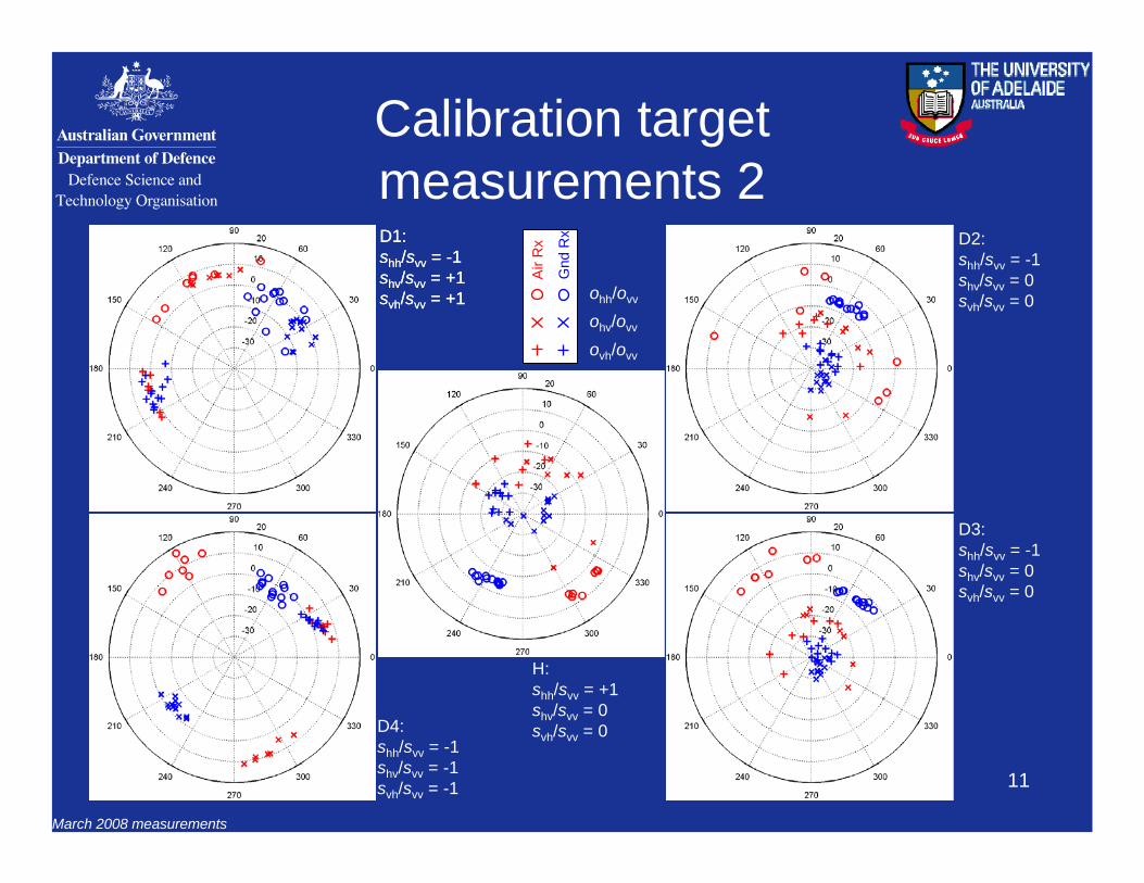
Calibration targetmeasurements 2
Air
Rx
Gnd
Rx
ohh/ovv
ohv/ovv
ovh/ovv
D1:shh/svv = -1shv/svv = +1svh/svv = +1
D1:shh/svv = -1shv/svv = +1svh/svv = +1
D2:shh/svv = -1shv/svv = 0svh/svv = 0
D3:shh/svv = -1shv/svv = 0svh/svv = 0
D4:shh/svv = -1shv/svv = -1svh/svv = -1
H:shh/svv = +1shv/svv = 0svh/svv = 0
March 2008 measurements
12
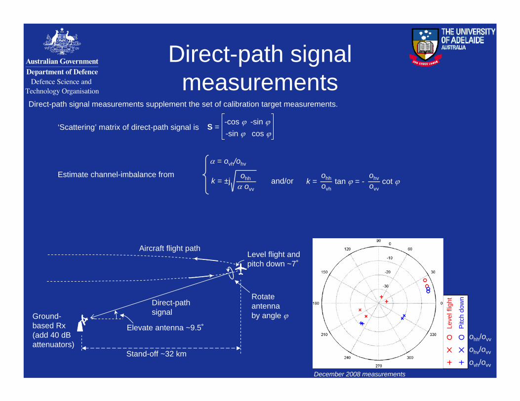
Direct-path signalmeasurements
December 2008 measurements
Leve
l flig
ht
Pitc
h do
wn
ohh/ovv
ohv/ovv
ovh/ovv
Direct-path signal measurements supplement the set of calibration target measurements.
cos ϕ-sin ϕ-sin ϕ-cos ϕS =
α = ovh/ohv
k = ±johh
α ovvk = tan ϕ = - cot ϕ
ohhovh
ohvovv
‘Scattering’ matrix of direct-path signal is
Estimate channel-imbalance fromand/or
Ground-based Rx (add 40 dB attenuators)
Aircraft flight path
Direct-path signal
Rotate antenna by angle ϕ
Level flight and pitch down ~7˚
Elevate antenna ~9.5˚
Stand-off ~32 km
13
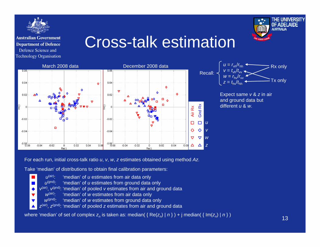
Cross-talk estimationMarch 2008 data December 2008 data
Air
Rx
Gnd
Rx
uvwz
For each run, initial cross-talk ratio u, v, w, z estimates obtained using method Az.
Take ‘median’ of distributions to obtain final calibration parameters:
‘median’ of w estimates from air data onlyw(air):‘median’ of w estimates from ground data onlyw(gnd):‘median’ of pooled z estimates from air and ground dataz(air), z(gnd):
‘median’ of pooled v estimates from air and ground datav(air), v(gnd):‘median’ of u estimates from ground data onlyu(gnd):‘median’ of u estimates from air data onlyu(air):
u = rvh/rhhv = tvh/tvvw = rhv/rvvz = thv/thh
Recall:Tx only
Rx only
where ‘median’ of set of complex zn is taken as: median( { Re(zn) | n } ) + j median( { Im(zn) | n } )
Expect same v & z in air and ground data but different u & w.
14
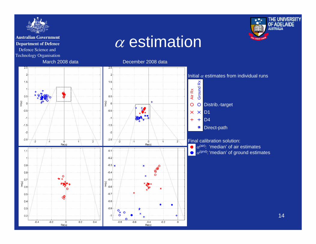
α estimation
Air
Rx
Gro
und
Rx
Distrib.-targetD1D4Direct-path
March 2008 data December 2008 data
Final calibration solution:
‘median’ of ground estimatesα(gnd):‘median’ of air estimatesα(air):
Initial α estimates from individual runs
15
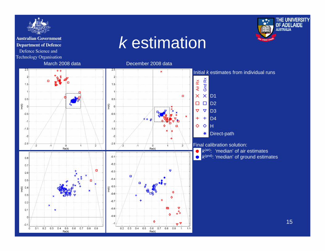
k estimation
Air
Rx
Gnd
Rx
D1D2D3D4HDirect-path
March 2008 data December 2008 data
Initial k estimates from individual runs
Final calibration solution:
‘median’ of ground estimatesk(gnd):‘median’ of air estimatesk(air):
16
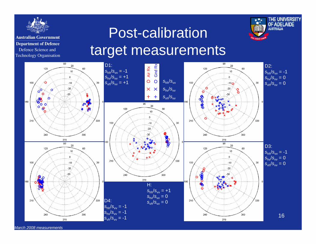
Post-calibrationtarget measurements
D1:shh/svv = -1shv/svv = +1svh/svv = +1
Air
Rx
Gnd
Rx
shh/svv
shv/svv
svh/svv
D2:shh/svv = -1shv/svv = 0svh/svv = 0
D3:shh/svv = -1shv/svv = 0svh/svv = 0
H:shh/svv = +1shv/svv = 0svh/svv = 0D4:
shh/svv = -1shv/svv = -1svh/svv = -1
March 2008 measurements
17
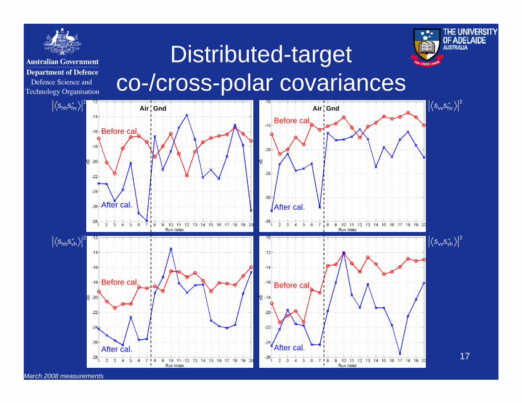
Distributed-targetco-/cross-polar covariances
shhshv* 2
shhsvh* 2
svvshv* 2
svvsvh* 2
Before cal.
After cal.
Before cal.
After cal.
Before cal.
After cal.
Before cal.
After cal.
March 2008 measurements
Air Gnd Air Gnd
18
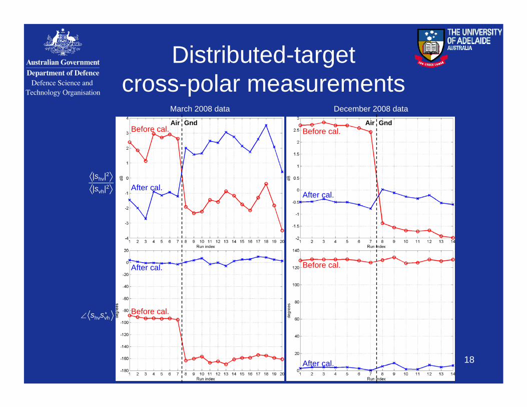
Distributed-targetcross-polar measurements
March 2008 data December 2008 data
|svh|2|shv|2
∠ shvsvh*
Before cal.
After cal.
Before cal.
After cal.
Before cal.
After cal.
Before cal.
After cal.
Air GndAir Gnd
19
Conclusion• A method for polarimetric calibration employing distributed-target,
calibration-target and direct-path signal measurements has been applied to the Ingara monostatic and bistatic data.
• High variability is present in calibration target measurements possibly related to large range of look angles (e.g. bistatic from 9˚ to 17˚): use Polarimetric Active Radar Calibrators (PARCs) in future?
• Assumptions of distributed-target azimuthal-symmetry, i.e. sii sij = 0, may not be valid: validity of cross-talk calibration solution is uncertain.
• Fair agreement in α and k channel-imbalance estimates from distributed-target, calibration target and direct-path signal measurements is found.
• Application of calibration solution to measurements produces results generally more consistent with those expected of calibrated data.
*
Top Related