
γλώσσες
Σελίδες
Νομικός

Laboratory Institute for Design of Electrical Measuring Instruments, Swatantryaveer Tatya Tope Marg, Chunabhatti, Sion, Mumbai, Maharashtra
Accreditation Standard ISO/IEC 17025:2005
Discipline Electro-Technical Calibration
Issue Date 31.08.2014
Certificate Number C-0085
Valid Until 30.08.2016
Last Amended on
23.09.2014
Page 1 of 12
Quantity Measured/ Instrument
Range / Frequency *Calibration Measurement
Capability ()
Remarks
Avijit Das
Neeraj Verma
Program Manager Convenor
SOURCE
1. DC Voltage# 100 mV 4 ppm Using Fluke 7001 with
Ref. Divider 752A by
Direct / Comparison
Method
1 V 3 ppm
10 V 2 ppm
2.
DC Resistance#
40 µΩ (1500A/60 mV)
60 µΩ (1000A/60 mV)
100 µΩ (600A/60 mV)
150 µΩ (400A/60 mV)
240 µΩ (250A/60 mV)
600 µΩ (100A/60 mV)
0.15 %
0.15 %
0.15 %
0.15 %
0.15 %
0.15 %
Using DC Shunts by Direct
Method
1 mΩ
8 mΩ
10 mΩ
16 mΩ
100 mΩ
0.006 %
0.01 %
0.004 %
0.01 %
0.004 %
Using Standard DC
Shunts/ Resistors by Direct
Method
1 Ω
10 kΩ
5 ppm
6 ppm
Using Reference Standard
by Direct Method
10 Ω 15 ppm Using Standard Resistor by
Direct Method 100 Ω 15 ppm
1 MΩ 40 ppm
10MΩ 16 ppm
100 MΩ 98 ppm
100 MΩ to 1GΩ 0.12 % to 0.5 % Using Decade Megohm
box by Direct Method
1GΩ 0.03 % Using Standard Resistor by
Direct Method
Laboratory Institute for Design of Electrical Measuring Instruments, Swatantryaveer Tatya Tope Marg, Chunabhatti, Sion, Mumbai, Maharashtra
Accreditation Standard ISO/IEC 17025:2005
Discipline Electro-Technical Calibration
Issue Date 31.08.2014
Certificate Number C-0085
Valid Until 30.08.2016
Last Amended on
23.09.2014
Page 2 of 12
Quantity Measured/ Instrument
Range / Frequency *Calibration Measurement
Capability ()
Remarks
Avijit Das
Neeraj Verma
Program Manager Convenor
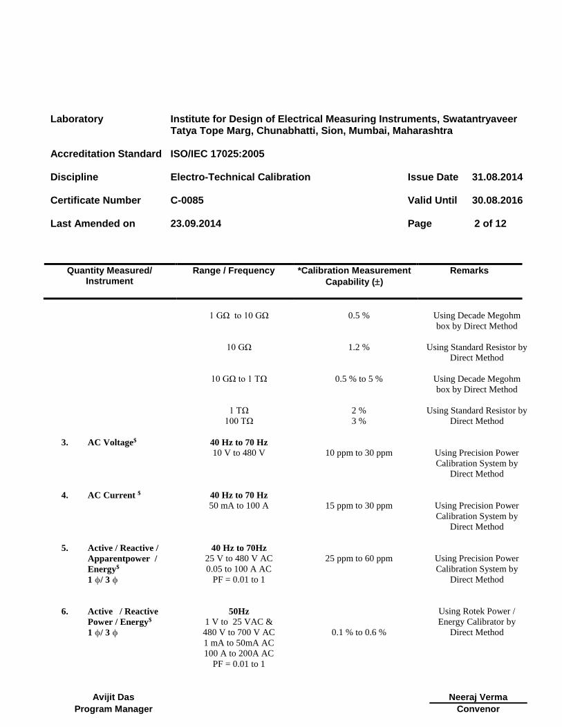
1 GΩ to 10 GΩ 0.5 % Using Decade Megohm
box by Direct Method
10 GΩ 1.2 % Using Standard Resistor by
Direct Method
10 GΩ to 1 TΩ 0.5 % to 5 % Using Decade Megohm
box by Direct Method
1 TΩ 2 % Using Standard Resistor by
Direct Method
100 TΩ 3 %
3.
AC Voltage$
40 Hz to 70 Hz
10 V to 480 V
10 ppm to 30 ppm
Using Precision Power
Calibration System by
Direct Method
4. AC Current $
40 Hz to 70 Hz
50 mA to 100 A
15 ppm to 30 ppm
Using Precision Power
Calibration System by
Direct Method
5. Active / Reactive /
Apparentpower /
Energy$
1 ϕ/ 3 ϕ
40 Hz to 70Hz
25 V to 480 V AC
0.05 to 100 A AC
PF = 0.01 to 1
25 ppm to 60 ppm
Using Precision Power
Calibration System by
Direct Method
6. Active / Reactive
Power / Energy$
1 ϕ/ 3 ϕ
50Hz
1 V to 25 VAC &
480 V to 700 V AC
1 mA to 50mA AC
100 A to 200A AC
PF = 0.01 to 1
0.1 % to 0.6 %
Using Rotek Power /
Energy Calibrator by
Direct Method
Laboratory Institute for Design of Electrical Measuring Instruments, Swatantryaveer Tatya Tope Marg, Chunabhatti, Sion, Mumbai, Maharashtra
Accreditation Standard ISO/IEC 17025:2005
Discipline Electro-Technical Calibration
Issue Date 31.08.2014
Certificate Number C-0085
Valid Until 30.08.2016
Last Amended on
23.09.2014
Page 3 of 12
Quantity Measured/ Instrument
Range / Frequency *Calibration Measurement
Capability ()
Remarks
Avijit Das
Neeraj Verma
Program Manager Convenor
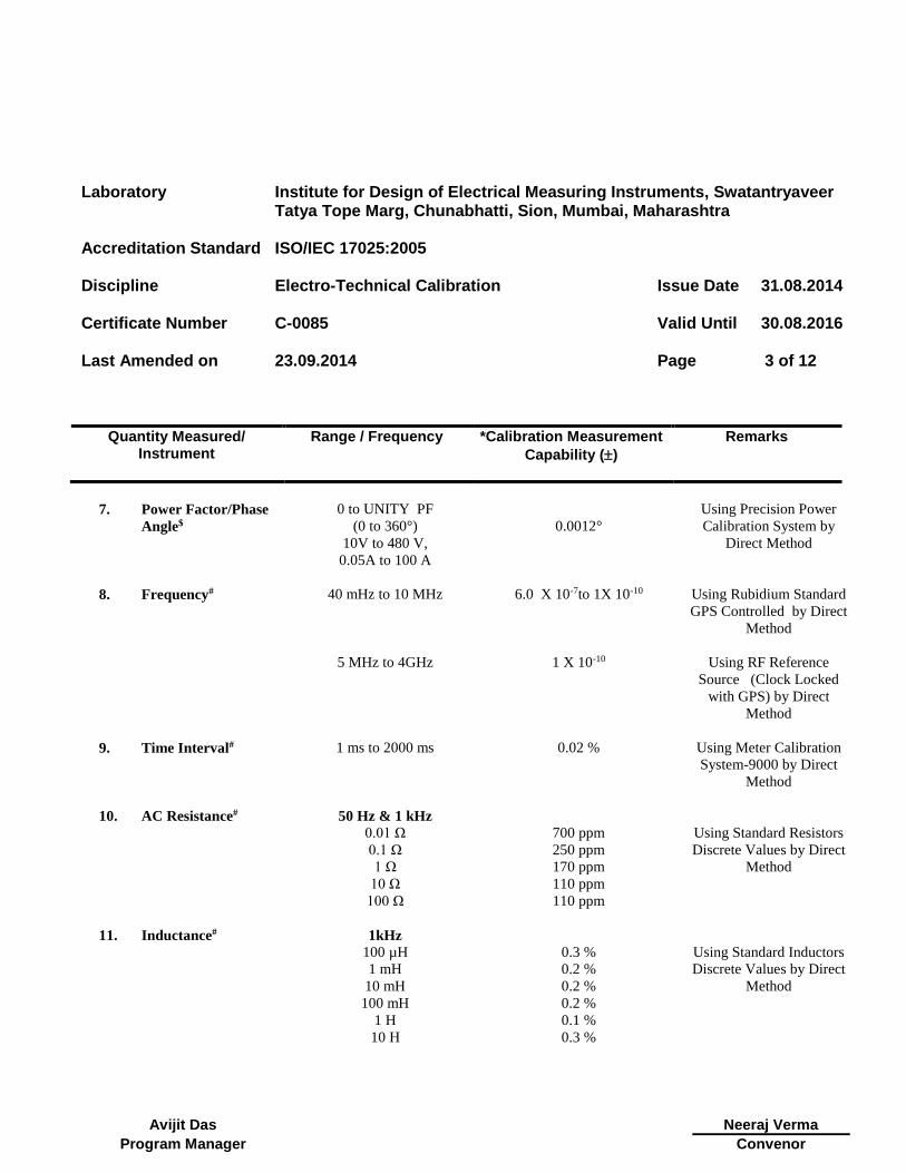
7. Power Factor/Phase
Angle$
0 to UNITY PF
(0 to 360°)
10V to 480 V,
0.05A to 100 A
0.0012°
Using Precision Power
Calibration System by
Direct Method
8. Frequency#
40 mHz to 10 MHz
5 MHz to 4GHz
6.0 X 10⁻⁷to 1X 10⁻¹⁰
1 X 10⁻¹⁰
Using Rubidium Standard
GPS Controlled by Direct
Method
Using RF Reference
Source (Clock Locked
with GPS) by Direct
Method
9. Time Interval#
1 ms to 2000 ms
0.02 % Using Meter Calibration
System-9000 by Direct
Method
10. AC Resistance#
50 Hz & 1 kHz
Using Standard Resistors
Discrete Values by Direct
Method
0.01 Ω 700 ppm
0.1 Ω 250 ppm
1 Ω 170 ppm
10 Ω 110 ppm
100 Ω
110 ppm
11. Inductance#
1kHz
Using Standard Inductors
Discrete Values by Direct
Method
100 µH 0.3 %
1 mH 0.2 %
10 mH 0.2 %
100 mH 0.2 %
1 H 0.1 %
10 H 0.3 %
Laboratory Institute for Design of Electrical Measuring Instruments, Swatantryaveer Tatya Tope Marg, Chunabhatti, Sion, Mumbai, Maharashtra
Accreditation Standard ISO/IEC 17025:2005
Discipline Electro-Technical Calibration
Issue Date 31.08.2014
Certificate Number C-0085
Valid Until 30.08.2016
Last Amended on
23.09.2014
Page 4 of 12
Quantity Measured/ Instrument
Range / Frequency *Calibration Measurement
Capability ()
Remarks
Avijit Das
Neeraj Verma
Program Manager Convenor
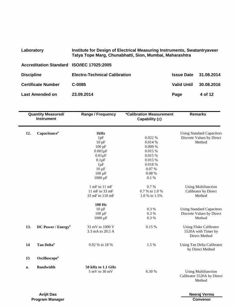
12. Capacitance#
1kHz
1pF
10 pF
100 pF
0.001µF
0.01µF
0.1µF
1µF
10 µF
100 µF
1000 µF
0.022 %
0.014 %
0.009 %
0.015 %
0.015 %
0.015 %
0.018 %
0.07 %
0.08 %
0.1 %
Using Standard Capacitors
Discrete Values by Direct
Method
1 mF to 11 mF 0.7 % Using Multifunction
Calibrator by Direct
Method
11 mF to 33 mF 0.7 % to 1.0 %
33 mF to 110 mF 1.0 % to 1.5%
100 Hz
Using Standard Capacitors
Discrete Values by Direct
Method
10 µF 0.3 %
100 µF 0.3 %
1000 µF
0.3 %
13. DC Power / Energy#
33 mV to 1000 V
3.3 mA to 20.5 A
0.15 % Using Fluke Calibrator
5520A with Timer by
Direct Method
14 Tan Delta#
0.02 % to 18 % 1.5 % Using Tan Delta Calibrator
by Direct Method
15 Oscilloscope#
a. Bandwidth 50 kHz to 1.1 GHz
5 mV to 30 mV
6.30 %
Using Multifunction
Calibrator 5520A by Direct
Method

Laboratory Institute for Design of Electrical Measuring Instruments, Swatantryaveer Tatya Tope Marg, Chunabhatti, Sion, Mumbai, Maharashtra
Accreditation Standard ISO/IEC 17025:2005
Discipline Electro-Technical Calibration
Issue Date 31.08.2014
Certificate Number C-0085
Valid Until 30.08.2016
Last Amended on
23.09.2014
Page 5 of 12
Quantity Measured/ Instrument
Range / Frequency *Calibration Measurement
Capability ()
Remarks
Avijit Das
Neeraj Verma
Program Manager Convenor
Amplitude
(Deflection Factor)
10 mV to 130V (1MΩ)
0.5 % to 0.2 %
10 mV to 6.6 V (50 Ω)
0.5 % to 0.2 %
b. Time Base (Marker)
1 ns to 5 s 20 ppm
16 Power Quality#
1 to 50
0.4 %
Using Multifunction
Calibrator 5520A by Direct
Method
Harmonics
17. Transformer Turns
Ratio (TTR) #
0.8 to 2000 0.05 % Using TTR Calibrator by
Direct Method
18. RF Power#
(With 50 Ω Level
head)
10 Hz to 128 MHz
+20dBm to + 24 dBm
100 mW to 251 mW
10 Hz to 1.4 GHz
-48 dBm to +20 dBm
15.85 nW to 100 mW
1.4 GHz to 4GHz
-48 dBm to +14 dBm
15.85 nW to 25.12mW
100 kHz to 4 GHz
-94 dBm to – 48dBm
0.398 pW to 15.85 nW
10 MHz to 3 GHz
-130 dBm to – 94 dBm
0.1fW to 0.398pW
4.6 %
6.0 %
15 %
30 %
50 %
Using RF Calibrator Model
-9640A by Direct Method
Laboratory Institute for Design of Electrical Measuring Instruments, Swatantryaveer Tatya Tope Marg, Chunabhatti, Sion, Mumbai, Maharashtra
Accreditation Standard ISO/IEC 17025:2005
Discipline Electro-Technical Calibration
Issue Date 31.08.2014
Certificate Number C-0085
Valid Until 30.08.2016
Last Amended on
23.09.2014
Page 6 of 12
Quantity Measured/ Instrument
Range / Frequency *Calibration Measurement
Capability ()
Remarks
Avijit Das
Neeraj Verma
Program Manager Convenor
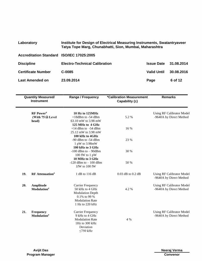
RF Power#
(With 75 Ω Level
head)
10 Hz to 125MHz
+18dBm to -54 dBm
63.10 mW to 3.98 mW
125 MHz to 4 GHz
+14 dBm to -54 dBm
25.12 mW to 3.98 mW
100 kHz to 4GHz
-90 dBm to -54 dBm
1 pW to 3.98mW
100 kHz to 3 GHz
-100 dBm to – 90dBm
100 fW to 1 pW
10 MHz to 3 GHz
-120 dBm to – 100 dBm
1fW to 100 fW
5.2 %
16 %
23 %
30 %
50 %
Using RF Calibrator Model
-9640A by Direct Method
19. RF Attenuation#
1 dB to 116 dB 0.03 dB to 0.2 dB Using RF Calibrator Model
-9640A by Direct Method
20. Amplitude
Modulation#
Carrier Frequency
50 kHz to 4 GHz
Modulation Depth
0.1% to 99 %
Modulation Rate
1 Hz to 220 kHz
4.2 %
Using RF Calibrator Model
-9640A by Direct Method
21. Frequency
Modulation#
Carrier Frequency
9 kHz to 4 GHz
Modulation Rate
1Hz to 300 kHz
Deviation
≤750 kHz
4 %
Using RF Calibrator Model
-9640A by Direct Method
Laboratory Institute for Design of Electrical Measuring Instruments, Swatantryaveer Tatya Tope Marg, Chunabhatti, Sion, Mumbai, Maharashtra
Accreditation Standard ISO/IEC 17025:2005
Discipline Electro-Technical Calibration
Issue Date 31.08.2014
Certificate Number C-0085
Valid Until 30.08.2016
Last Amended on
23.09.2014
Page 7 of 12
Quantity Measured/ Instrument
Range / Frequency *Calibration Measurement
Capability ()
Remarks
Avijit Das
Neeraj Verma
Program Manager Convenor
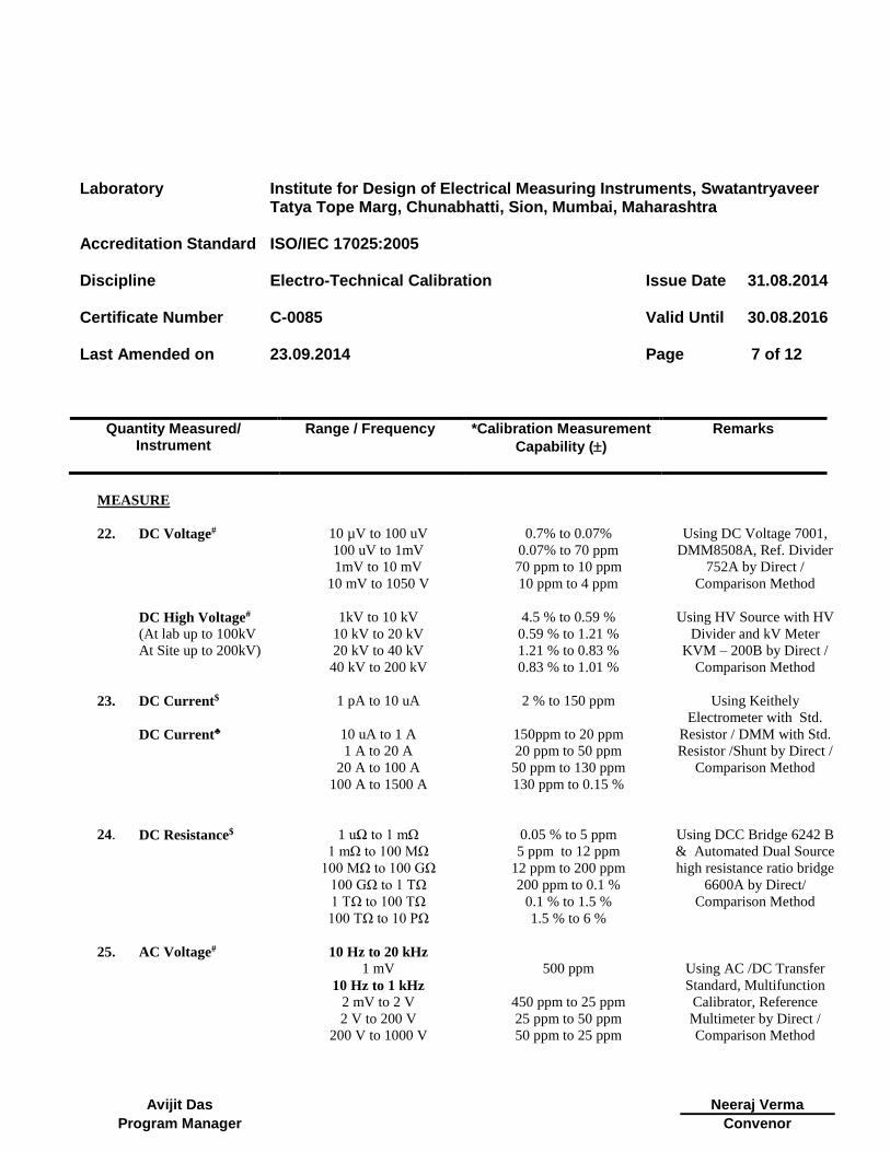
MEASURE
22. DC Voltage#
10 µV to 100 uV
100 uV to 1mV
1mV to 10 mV
10 mV to 1050 V
0.7% to 0.07%
0.07% to 70 ppm
70 ppm to 10 ppm
10 ppm to 4 ppm
Using DC Voltage 7001,
DMM8508A, Ref. Divider
752A by Direct /
Comparison Method
DC High Voltage#
(At lab up to 100kV
At Site up to 200kV)
1kV to 10 kV
10 kV to 20 kV
20 kV to 40 kV
40 kV to 200 kV
4.5 % to 0.59 %
0.59 % to 1.21 %
1.21 % to 0.83 %
0.83 % to 1.01 %
Using HV Source with HV
Divider and kV Meter
KVM – 200B by Direct /
Comparison Method
23. DC Current$ 1 pA to 10 uA
2 % to 150 ppm Using Keithely
Electrometer with Std.
Resistor / DMM with Std.
Resistor /Shunt by Direct /
Comparison Method
DC Current♣
10 uA to 1 A
1 A to 20 A
20 A to 100 A
100 A to 1500 A
150ppm to 20 ppm
20 ppm to 50 ppm
50 ppm to 130 ppm
130 ppm to 0.15 %
24. DC Resistance$
1 uΩ to 1 mΩ
1 mΩ to 100 MΩ
100 MΩ to 100 GΩ
100 GΩ to 1 TΩ
1 TΩ to 100 TΩ
100 TΩ to 10 PΩ
0.05 % to 5 ppm
5 ppm to 12 ppm
12 ppm to 200 ppm
200 ppm to 0.1 %
0.1 % to 1.5 %
1.5 % to 6 %
Using DCC Bridge 6242 B
& Automated Dual Source
high resistance ratio bridge
6600A by Direct/
Comparison Method
25. AC Voltage#
10 Hz to 20 kHz
1 mV
10 Hz to 1 kHz
2 mV to 2 V
2 V to 200 V
200 V to 1000 V
500 ppm
450 ppm to 25 ppm
25 ppm to 50 ppm
50 ppm to 25 ppm
Using AC /DC Transfer
Standard, Multifunction
Calibrator, Reference
Multimeter by Direct /
Comparison Method
Laboratory Institute for Design of Electrical Measuring Instruments, Swatantryaveer Tatya Tope Marg, Chunabhatti, Sion, Mumbai, Maharashtra
Accreditation Standard ISO/IEC 17025:2005
Discipline Electro-Technical Calibration
Issue Date 31.08.2014
Certificate Number C-0085
Valid Until 30.08.2016
Last Amended on
23.09.2014
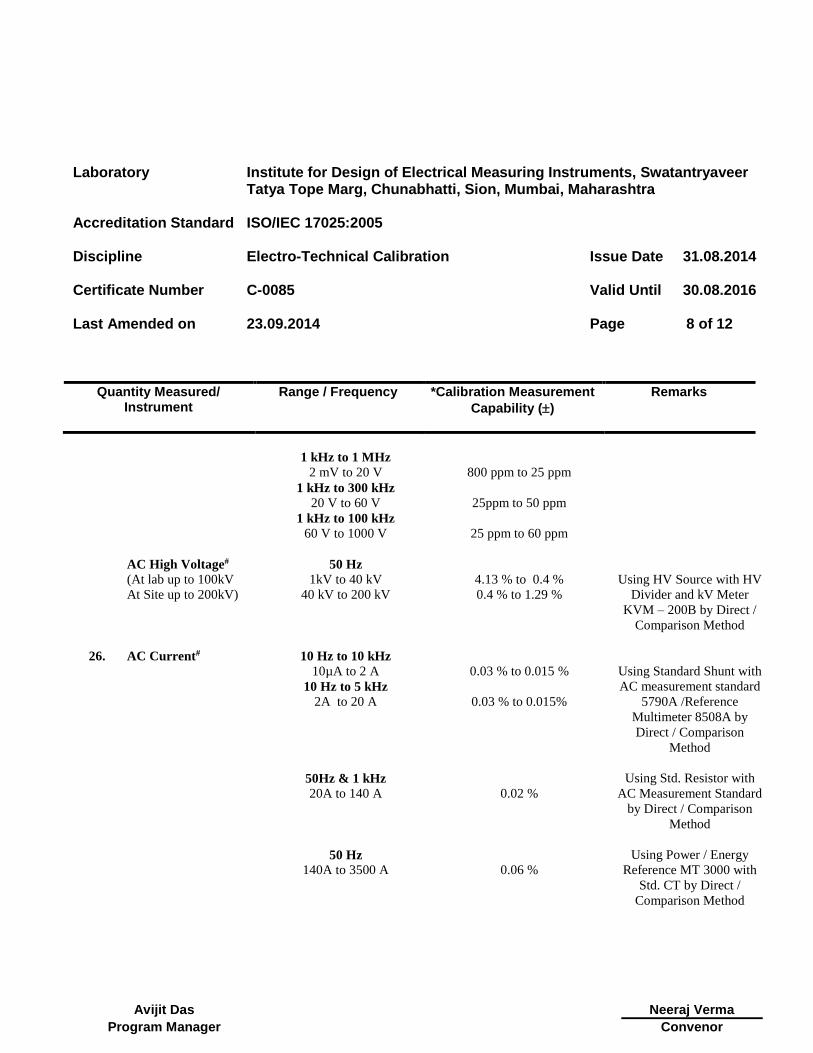
Page 8 of 12
Quantity Measured/ Instrument
Range / Frequency *Calibration Measurement
Capability ()
Remarks
Avijit Das
Neeraj Verma
Program Manager Convenor
1 kHz to 1 MHz
2 mV to 20 V
800 ppm to 25 ppm
1 kHz to 300 kHz
20 V to 60 V
25ppm to 50 ppm
1 kHz to 100 kHz
60 V to 1000 V
25 ppm to 60 ppm
AC High Voltage#
(At lab up to 100kV
At Site up to 200kV)
50 Hz
1kV to 40 kV
40 kV to 200 kV
4.13 % to 0.4 %
0.4 % to 1.29 %
Using HV Source with HV
Divider and kV Meter
KVM – 200B by Direct /
Comparison Method
26. AC Current#
10 Hz to 10 kHz
10µA to 2 A
0.03 % to 0.015 %
Using Standard Shunt with
AC measurement standard
5790A /Reference
Multimeter 8508A by
Direct / Comparison
Method
10 Hz to 5 kHz
2A to 20 A
0.03 % to 0.015%
50Hz & 1 kHz
20A to 140 A
0.02 %
Using Std. Resistor with
AC Measurement Standard
by Direct / Comparison
Method
50 Hz
140A to 3500 A
0.06 %
Using Power / Energy
Reference MT 3000 with
Std. CT by Direct /
Comparison Method
Laboratory Institute for Design of Electrical Measuring Instruments, Swatantryaveer Tatya Tope Marg, Chunabhatti, Sion, Mumbai, Maharashtra
Accreditation Standard ISO/IEC 17025:2005
Discipline Electro-Technical Calibration
Issue Date 31.08.2014
Certificate Number C-0085
Valid Until 30.08.2016
Last Amended on
23.09.2014
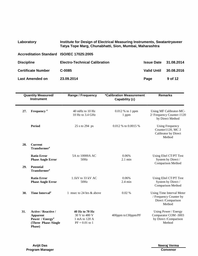
Page 9 of 12
Quantity Measured/ Instrument
Range / Frequency *Calibration Measurement
Capability ()
Remarks
Avijit Das
Neeraj Verma
Program Manager Convenor
27. Frequency #
Period
40 mHz to 10 Hz
10 Hz to 3.4 GHz
25 s to 294 ps
0.012 % to 1 ppm
1 ppm
0.012 % to 0.0015 %
Using MF Calibrator-MC-
2/ Frequency Counter-1120
by Direct Method
Using Frequency
Counter1120, MC 2
Calibrator by Direct
Method
28. Current
Transformer#
Ratio Error
Phase Angle Error
5A to 10000A AC
50Hz
0.06%
2.1 min
Using Eltel CT/PT Test
System by Direct /
Comparison Method
29. Potential
Transformer#
Ratio Error
Phase Angle Error
1.1kV to 33 kV AC
50Hz
0.06%
2.4 min
Using Eltel CT/PT Test
System by Direct /
Comparison Method
30. Time Interval#
1 msec to 24 hrs & above 0.02 % Using Time Interval Meter
/ Frequency Counter by
Direct /Comparison
Method
31. Active / Reactive /
Apparent
Power / Energy#
(Three Phase /Single
Phase)
40 Hz to 70 Hz
30 V to 480 V
1 mA to 120 A
PF = 0.01 to 1
400ppm to130ppm/PF
Using Power / Energy
Comparator COM -3003
by Direct /Comparison
Method

Laboratory Institute for Design of Electrical Measuring Instruments, Swatantryaveer Tatya Tope Marg, Chunabhatti, Sion, Mumbai, Maharashtra
Accreditation Standard ISO/IEC 17025:2005
Discipline Electro-Technical Calibration
Issue Date 31.08.2014
Certificate Number C-0085
Valid Until 30.08.2016
Last Amended on
23.09.2014
Page 10 of 12
Quantity Measured/ Instrument
Range / Frequency *Calibration Measurement
Capability ()
Remarks
Avijit Das
Neeraj Verma
Program Manager Convenor
40 Hz to 70Hz
40 V to 480 V
120 A to 300 A
PF = 0.01 to 1
0.03% to 0.25% / PF
Using Power / Energy Test
System , MT 3000 by
Direct /Comparison
Method
32. Power Factor
Phase Angle#
50 Hz
0 to UNITY PF
(0 to 360°)
30V to 320 V,
1 mA to 120 A
0.008°
Using Power / Energy
Comparator COM -3003
by Direct /Comparison
Method
33. Capacitance#
1 kHz
10 pF to 1 nF
1 nF to 100 uF
100 uF to 100 mF
0.6 %
0.6 % to 0.06 %
0.06% to 0.6 %
Using RLC DigiBridge,
1689 by Direct
/Comparison Method
100 Hz
1 uF to 1 mF
1 mF to 10 mF
0.12 % to 0.3 %
0.3 % to 1.4 %
34. Inductance#
1 kHz
100 µH to 100 mH
100 mH to 10 H
0.26% to 0.04 %
0.04% to 0.06 %
Using RLC DigiBridge,
1689 by Direct
/Comparison Method
35. AC Resistance#
1 kHz
100 mΩ to 1 Ω
1 Ω to 10 k Ω
10 kΩ to 10 MΩ
50 Hz
0.1 Ω to 1 MΩ
0.83% to 0.1 %
0.1% to 0.05 %
0.05% to 0.3 %
0.3 to 0.6 %
Using RLC DigiBridge,
1689 by Direct
/Comparison Method
Laboratory Institute for Design of Electrical Measuring Instruments, Swatantryaveer Tatya Tope Marg, Chunabhatti, Sion, Mumbai, Maharashtra
Accreditation Standard ISO/IEC 17025:2005
Discipline Electro-Technical Calibration
Issue Date 31.08.2014
Certificate Number C-0085
Valid Until 30.08.2016
Last Amended on
23.09.2014
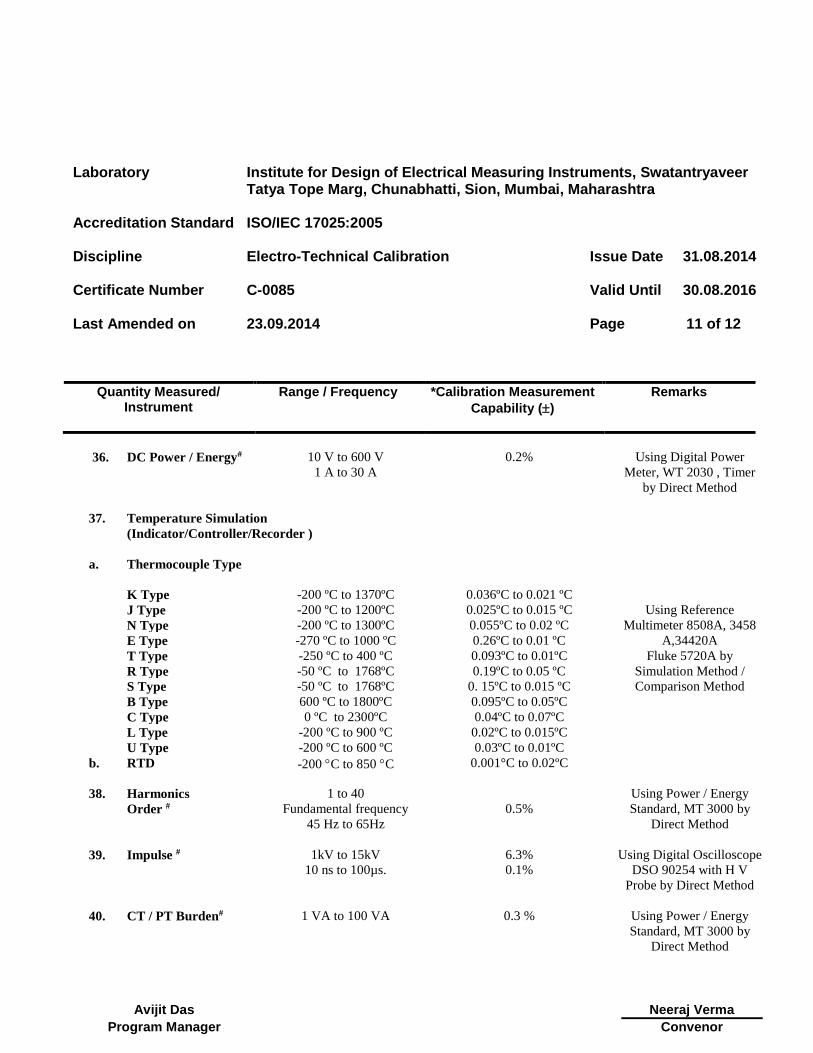
Page 11 of 12
Quantity Measured/ Instrument
Range / Frequency *Calibration Measurement
Capability ()
Remarks
Avijit Das
Neeraj Verma
Program Manager Convenor
36. DC Power / Energy#
10 V to 600 V
1 A to 30 A
0.2% Using Digital Power
Meter, WT 2030 , Timer
by Direct Method
37. Temperature Simulation
(Indicator/Controller/Recorder )
a. Thermocouple Type
K Type -200 ºC to 1370ºC 0.036ºC to 0.021 ºC
Using Reference
Multimeter 8508A, 3458
A,34420A
Fluke 5720A by
Simulation Method /
Comparison Method
J Type -200 ºC to 1200ºC 0.025ºC to 0.015 ºC
N Type -200 ºC to 1300ºC 0.055ºC to 0.02 ºC
E Type -270 ºC to 1000 ºC 0.26ºC to 0.01 ºC
T Type -250 ºC to 400 ºC 0.093ºC to 0.01ºC
R Type -50 ºC to 1768ºC 0.19ºC to 0.05 ºC
S Type -50 ºC to 1768ºC 0. 15ºC to 0.015 ºC
B Type 600 ºC to 1800ºC 0.095ºC to 0.05ºC
C Type 0 ºC to 2300ºC 0.04ºC to 0.07ºC
L Type -200 ºC to 900 ºC 0.02ºC to 0.015ºC
U Type -200 ºC to 600 ºC 0.03ºC to 0.01ºC
b. RTD
-200 C to 850 C 0.001°C to 0.02ºC
38. Harmonics
Order #
1 to 40
Fundamental frequency
45 Hz to 65Hz
0.5%
Using Power / Energy
Standard, MT 3000 by
Direct Method
39. Impulse #
1kV to 15kV
10 ns to 100µs.
6.3%
0.1%
Using Digital Oscilloscope
DSO 90254 with H V
Probe by Direct Method
40. CT / PT Burden#
1 VA to 100 VA 0.3 % Using Power / Energy
Standard, MT 3000 by
Direct Method
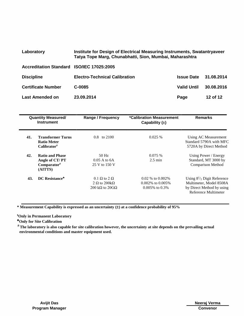
Laboratory Institute for Design of Electrical Measuring Instruments, Swatantryaveer Tatya Tope Marg, Chunabhatti, Sion, Mumbai, Maharashtra
Accreditation Standard ISO/IEC 17025:2005
Discipline Electro-Technical Calibration
Issue Date 31.08.2014
Certificate Number C-0085
Valid Until 30.08.2016
Last Amended on
23.09.2014
Page 12 of 12
Quantity Measured/ Instrument
Range / Frequency *Calibration Measurement
Capability ()
Remarks
Avijit Das
Neeraj Verma
Program Manager Convenor
41. Transformer Turns
Ratio Meter
Calibrator#
0.8 to 2100 0.025 % Using AC Measurement
Standard 5790A with MFC
5720A by Direct Method
42. Ratio and Phase
Angle of CT/ PT
Comparator#
(AITTS)
50 Hz
0.05 A to 6A
25 V to 150 V
0.075 %
2.5 min
Using Power / Energy
Standard, MT 3000 by
Comparison Method
43. DC Resistance♣
0.1 Ω to 2 Ω 0.02 % to 0.002% Using 81/2 Digit Reference
Multimeter, Model 8508A
by Direct Method by using
Reference Multimeter
2 Ω to 200kΩ 0.002% to 0.005%
200 kΩ to 20GΩ 0.005% to 0.3%
* Measurement Capability is expressed as an uncertainty () at a confidence probability of 95%
$Only in Permanent Laboratory ♣Only for Site Calibration # The laboratory is also capable for site calibration however, the uncertainty at site depends on the prevailing actual
environmental conditions and master equipment used.
Top Related