Laboratory Institute for Design of Electrical Measuring ...
12
Laboratory Institute for Design of Electrical Measuring Instruments, Swatantryaveer Tatya Tope Marg, Chunabhatti, Sion, Mumbai, Maharashtra Accreditation Standard ISO/IEC 17025:2005 Discipline Electro-Technical Calibration Issue Date 31.08.2014 Certificate Number C-0085 Valid Until 30.08.2016 Last Amended on 23.09.2014 Page 1 of 12 Quantity Measured/ Instrument Range / Frequency *Calibration Measurement Capability () Remarks Avijit Das Neeraj Verma Program Manager Convenor SOURCE 1. DC Voltage # 100 mV 4 ppm Using Fluke 7001 with Ref. Divider 752A by Direct / Comparison Method 1 V 3 ppm 10 V 2 ppm 2. DC Resistance # 40 µΩ (1500A/60 mV) 60 µΩ (1000A/60 mV) 100 µΩ (600A/60 mV) 150 µΩ (400A/60 mV) 240 µΩ (250A/60 mV) 600 µΩ (100A/60 mV) 0.15 % 0.15 % 0.15 % 0.15 % 0.15 % 0.15 % Using DC Shunts by Direct Method 1 mΩ 8 mΩ 10 mΩ 16 mΩ 100 mΩ 0.006 % 0.01 % 0.004 % 0.01 % 0.004 % Using Standard DC Shunts/ Resistors by Direct Method 1 Ω 10 kΩ 5 ppm 6 ppm Using Reference Standard by Direct Method 10 Ω 15 ppm Using Standard Resistor by Direct Method 100 Ω 15 ppm 1 MΩ 40 ppm 10MΩ 16 ppm 100 MΩ 98 ppm 100 MΩ to 1GΩ 0.12 % to 0.5 % Using Decade Megohm box by Direct Method 1GΩ 0.03 % Using Standard Resistor by Direct Method
Transcript of Laboratory Institute for Design of Electrical Measuring ...
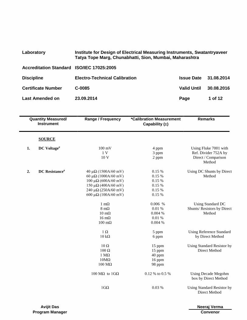
Laboratory Institute for Design of Electrical Measuring Instruments, Swatantryaveer Tatya Tope Marg, Chunabhatti, Sion, Mumbai, Maharashtra
Accreditation Standard ISO/IEC 17025:2005
Discipline Electro-Technical Calibration
Issue Date 31.08.2014
Certificate Number C-0085
Valid Until 30.08.2016
Last Amended on
23.09.2014
Page 1 of 12
Quantity Measured/ Instrument
Range / Frequency *Calibration Measurement
Capability ()
Remarks
Avijit Das
Neeraj Verma
Program Manager Convenor
SOURCE
1. DC Voltage# 100 mV 4 ppm Using Fluke 7001 with
Ref. Divider 752A by
Direct / Comparison
Method
1 V 3 ppm
10 V 2 ppm
2.
DC Resistance#
40 µΩ (1500A/60 mV)
60 µΩ (1000A/60 mV)
100 µΩ (600A/60 mV)
150 µΩ (400A/60 mV)
240 µΩ (250A/60 mV)
600 µΩ (100A/60 mV)
0.15 %
0.15 %
0.15 %
0.15 %
0.15 %
0.15 %
Using DC Shunts by Direct
Method
1 mΩ
8 mΩ
10 mΩ
16 mΩ
100 mΩ
0.006 %
0.01 %
0.004 %
0.01 %
0.004 %
Using Standard DC
Shunts/ Resistors by Direct
Method
1 Ω
10 kΩ
5 ppm
6 ppm
Using Reference Standard
by Direct Method
10 Ω 15 ppm Using Standard Resistor by
Direct Method 100 Ω 15 ppm
1 MΩ 40 ppm
10MΩ 16 ppm
100 MΩ 98 ppm
100 MΩ to 1GΩ 0.12 % to 0.5 % Using Decade Megohm
box by Direct Method
1GΩ 0.03 % Using Standard Resistor by
Direct Method
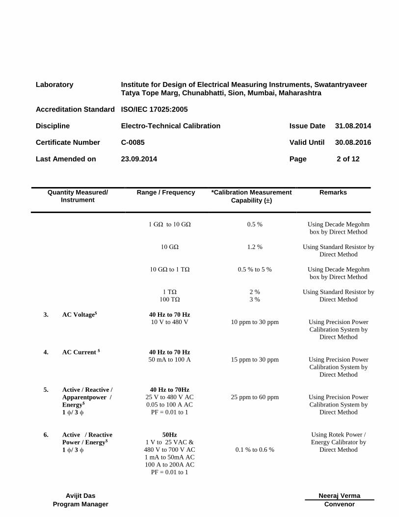
Laboratory Institute for Design of Electrical Measuring Instruments, Swatantryaveer Tatya Tope Marg, Chunabhatti, Sion, Mumbai, Maharashtra
Accreditation Standard ISO/IEC 17025:2005
Discipline Electro-Technical Calibration
Issue Date 31.08.2014
Certificate Number C-0085
Valid Until 30.08.2016
Last Amended on
23.09.2014
Page 2 of 12
Quantity Measured/ Instrument
Range / Frequency *Calibration Measurement
Capability ()
Remarks
Avijit Das
Neeraj Verma
Program Manager Convenor
1 GΩ to 10 GΩ 0.5 % Using Decade Megohm
box by Direct Method
10 GΩ 1.2 % Using Standard Resistor by
Direct Method
10 GΩ to 1 TΩ 0.5 % to 5 % Using Decade Megohm
box by Direct Method
1 TΩ 2 % Using Standard Resistor by
Direct Method
100 TΩ 3 %
3.
AC Voltage$
40 Hz to 70 Hz
10 V to 480 V
10 ppm to 30 ppm
Using Precision Power
Calibration System by
Direct Method
4. AC Current $
40 Hz to 70 Hz
50 mA to 100 A
15 ppm to 30 ppm
Using Precision Power
Calibration System by
Direct Method
5. Active / Reactive /
Apparentpower /
Energy$
1 ϕ/ 3 ϕ
40 Hz to 70Hz
25 V to 480 V AC
0.05 to 100 A AC
PF = 0.01 to 1
25 ppm to 60 ppm
Using Precision Power
Calibration System by
Direct Method
6. Active / Reactive
Power / Energy$
1 ϕ/ 3 ϕ
50Hz
1 V to 25 VAC &
480 V to 700 V AC
1 mA to 50mA AC
100 A to 200A AC
PF = 0.01 to 1
0.1 % to 0.6 %
Using Rotek Power /
Energy Calibrator by
Direct Method
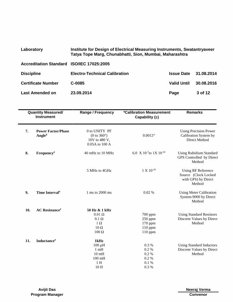
Laboratory Institute for Design of Electrical Measuring Instruments, Swatantryaveer Tatya Tope Marg, Chunabhatti, Sion, Mumbai, Maharashtra
Accreditation Standard ISO/IEC 17025:2005
Discipline Electro-Technical Calibration
Issue Date 31.08.2014
Certificate Number C-0085
Valid Until 30.08.2016
Last Amended on
23.09.2014
Page 3 of 12
Quantity Measured/ Instrument
Range / Frequency *Calibration Measurement
Capability ()
Remarks
Avijit Das
Neeraj Verma
Program Manager Convenor
7. Power Factor/Phase
Angle$
0 to UNITY PF
(0 to 360°)
10V to 480 V,
0.05A to 100 A
0.0012°
Using Precision Power
Calibration System by
Direct Method
8. Frequency#
40 mHz to 10 MHz
5 MHz to 4GHz
6.0 X 10⁻⁷to 1X 10⁻¹⁰
1 X 10⁻¹⁰
Using Rubidium Standard
GPS Controlled by Direct
Method
Using RF Reference
Source (Clock Locked
with GPS) by Direct
Method
9. Time Interval#
1 ms to 2000 ms
0.02 % Using Meter Calibration
System-9000 by Direct
Method
10. AC Resistance#
50 Hz & 1 kHz
Using Standard Resistors
Discrete Values by Direct
Method
0.01 Ω 700 ppm
0.1 Ω 250 ppm
1 Ω 170 ppm
10 Ω 110 ppm
100 Ω
110 ppm
11. Inductance#
1kHz
Using Standard Inductors
Discrete Values by Direct
Method
100 µH 0.3 %
1 mH 0.2 %
10 mH 0.2 %
100 mH 0.2 %
1 H 0.1 %
10 H 0.3 %
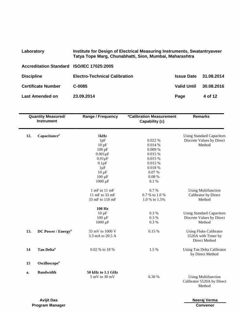
Laboratory Institute for Design of Electrical Measuring Instruments, Swatantryaveer Tatya Tope Marg, Chunabhatti, Sion, Mumbai, Maharashtra
Accreditation Standard ISO/IEC 17025:2005
Discipline Electro-Technical Calibration
Issue Date 31.08.2014
Certificate Number C-0085
Valid Until 30.08.2016
Last Amended on
23.09.2014
Page 4 of 12
Quantity Measured/ Instrument
Range / Frequency *Calibration Measurement
Capability ()
Remarks
Avijit Das
Neeraj Verma
Program Manager Convenor
12. Capacitance#
1kHz
1pF
10 pF
100 pF
0.001µF
0.01µF
0.1µF
1µF
10 µF
100 µF
1000 µF
0.022 %
0.014 %
0.009 %
0.015 %
0.015 %
0.015 %
0.018 %
0.07 %
0.08 %
0.1 %
Using Standard Capacitors
Discrete Values by Direct
Method
1 mF to 11 mF 0.7 % Using Multifunction
Calibrator by Direct
Method
11 mF to 33 mF 0.7 % to 1.0 %
33 mF to 110 mF 1.0 % to 1.5%
100 Hz
Using Standard Capacitors
Discrete Values by Direct
Method
10 µF 0.3 %
100 µF 0.3 %
1000 µF
0.3 %
13. DC Power / Energy#
33 mV to 1000 V
3.3 mA to 20.5 A
0.15 % Using Fluke Calibrator
5520A with Timer by
Direct Method
14 Tan Delta#
0.02 % to 18 % 1.5 % Using Tan Delta Calibrator
by Direct Method
15 Oscilloscope#
a. Bandwidth 50 kHz to 1.1 GHz
5 mV to 30 mV
6.30 %
Using Multifunction
Calibrator 5520A by Direct
Method

Laboratory Institute for Design of Electrical Measuring Instruments, Swatantryaveer Tatya Tope Marg, Chunabhatti, Sion, Mumbai, Maharashtra
Accreditation Standard ISO/IEC 17025:2005
Discipline Electro-Technical Calibration
Issue Date 31.08.2014
Certificate Number C-0085
Valid Until 30.08.2016
Last Amended on
23.09.2014
Page 5 of 12
Quantity Measured/ Instrument
Range / Frequency *Calibration Measurement
Capability ()
Remarks
Avijit Das
Neeraj Verma
Program Manager Convenor
Amplitude
(Deflection Factor)
10 mV to 130V (1MΩ)
0.5 % to 0.2 %
10 mV to 6.6 V (50 Ω)
0.5 % to 0.2 %
b. Time Base (Marker)
1 ns to 5 s 20 ppm
16 Power Quality#
1 to 50
0.4 %
Using Multifunction
Calibrator 5520A by Direct
Method
Harmonics
17. Transformer Turns
Ratio (TTR) #
0.8 to 2000 0.05 % Using TTR Calibrator by
Direct Method
18. RF Power#
(With 50 Ω Level
head)
10 Hz to 128 MHz
+20dBm to + 24 dBm
100 mW to 251 mW
10 Hz to 1.4 GHz
-48 dBm to +20 dBm
15.85 nW to 100 mW
1.4 GHz to 4GHz
-48 dBm to +14 dBm
15.85 nW to 25.12mW
100 kHz to 4 GHz
-94 dBm to – 48dBm
0.398 pW to 15.85 nW
10 MHz to 3 GHz
-130 dBm to – 94 dBm
0.1fW to 0.398pW
4.6 %
6.0 %
15 %
30 %
50 %
Using RF Calibrator Model
-9640A by Direct Method
Laboratory Institute for Design of Electrical Measuring Instruments, Swatantryaveer Tatya Tope Marg, Chunabhatti, Sion, Mumbai, Maharashtra
Accreditation Standard ISO/IEC 17025:2005
Discipline Electro-Technical Calibration
Issue Date 31.08.2014
Certificate Number C-0085
Valid Until 30.08.2016
Last Amended on
23.09.2014
Page 6 of 12
Quantity Measured/ Instrument
Range / Frequency *Calibration Measurement
Capability ()
Remarks
Avijit Das
Neeraj Verma
Program Manager Convenor
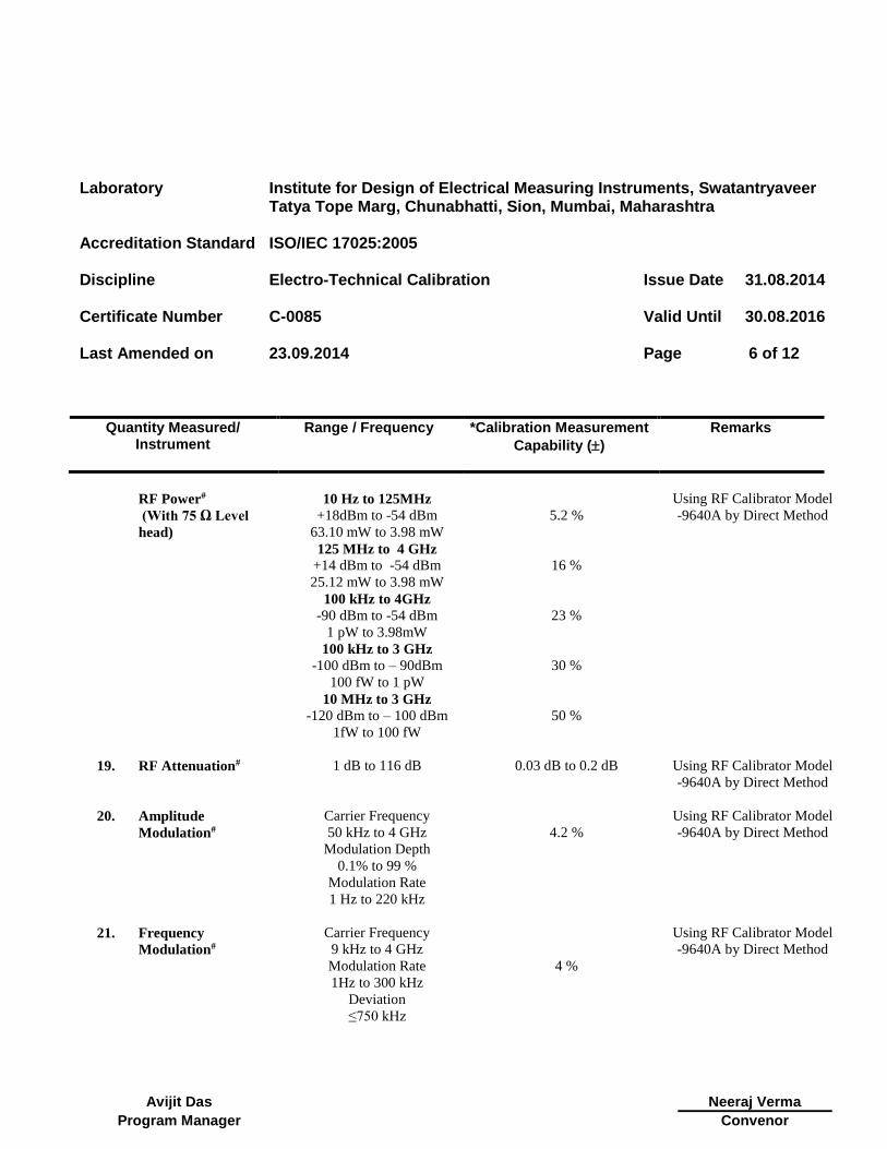
RF Power#
(With 75 Ω Level
head)
10 Hz to 125MHz
+18dBm to -54 dBm
63.10 mW to 3.98 mW
125 MHz to 4 GHz
+14 dBm to -54 dBm
25.12 mW to 3.98 mW
100 kHz to 4GHz
-90 dBm to -54 dBm
1 pW to 3.98mW
100 kHz to 3 GHz
-100 dBm to – 90dBm
100 fW to 1 pW
10 MHz to 3 GHz
-120 dBm to – 100 dBm
1fW to 100 fW
5.2 %
16 %
23 %
30 %
50 %
Using RF Calibrator Model
-9640A by Direct Method
19. RF Attenuation#
1 dB to 116 dB 0.03 dB to 0.2 dB Using RF Calibrator Model
-9640A by Direct Method
20. Amplitude
Modulation#
Carrier Frequency
50 kHz to 4 GHz
Modulation Depth
0.1% to 99 %
Modulation Rate
1 Hz to 220 kHz
4.2 %
Using RF Calibrator Model
-9640A by Direct Method
21. Frequency
Modulation#
Carrier Frequency
9 kHz to 4 GHz
Modulation Rate
1Hz to 300 kHz
Deviation
≤750 kHz
4 %
Using RF Calibrator Model
-9640A by Direct Method
Laboratory Institute for Design of Electrical Measuring Instruments, Swatantryaveer Tatya Tope Marg, Chunabhatti, Sion, Mumbai, Maharashtra
Accreditation Standard ISO/IEC 17025:2005
Discipline Electro-Technical Calibration
Issue Date 31.08.2014
Certificate Number C-0085
Valid Until 30.08.2016
Last Amended on
23.09.2014
Page 7 of 12
Quantity Measured/ Instrument
Range / Frequency *Calibration Measurement
Capability ()
Remarks
Avijit Das
Neeraj Verma
Program Manager Convenor
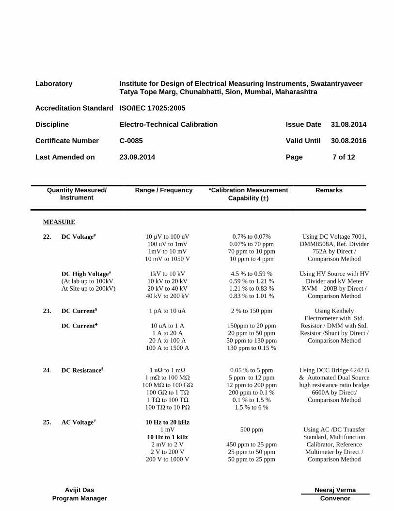
MEASURE
22. DC Voltage#
10 µV to 100 uV
100 uV to 1mV
1mV to 10 mV
10 mV to 1050 V
0.7% to 0.07%
0.07% to 70 ppm
70 ppm to 10 ppm
10 ppm to 4 ppm
Using DC Voltage 7001,
DMM8508A, Ref. Divider
752A by Direct /
Comparison Method
DC High Voltage#
(At lab up to 100kV
At Site up to 200kV)
1kV to 10 kV
10 kV to 20 kV
20 kV to 40 kV
40 kV to 200 kV
4.5 % to 0.59 %
0.59 % to 1.21 %
1.21 % to 0.83 %
0.83 % to 1.01 %
Using HV Source with HV
Divider and kV Meter
KVM – 200B by Direct /
Comparison Method
23. DC Current$ 1 pA to 10 uA
2 % to 150 ppm Using Keithely
Electrometer with Std.
Resistor / DMM with Std.
Resistor /Shunt by Direct /
Comparison Method
DC Current♣
10 uA to 1 A
1 A to 20 A
20 A to 100 A
100 A to 1500 A
150ppm to 20 ppm
20 ppm to 50 ppm
50 ppm to 130 ppm
130 ppm to 0.15 %
24. DC Resistance$
1 uΩ to 1 mΩ
1 mΩ to 100 MΩ
100 MΩ to 100 GΩ
100 GΩ to 1 TΩ
1 TΩ to 100 TΩ
100 TΩ to 10 PΩ
0.05 % to 5 ppm
5 ppm to 12 ppm
12 ppm to 200 ppm
200 ppm to 0.1 %
0.1 % to 1.5 %
1.5 % to 6 %
Using DCC Bridge 6242 B
& Automated Dual Source
high resistance ratio bridge
6600A by Direct/
Comparison Method
25. AC Voltage#
10 Hz to 20 kHz
1 mV
10 Hz to 1 kHz
2 mV to 2 V
2 V to 200 V
200 V to 1000 V
500 ppm
450 ppm to 25 ppm
25 ppm to 50 ppm
50 ppm to 25 ppm
Using AC /DC Transfer
Standard, Multifunction
Calibrator, Reference
Multimeter by Direct /
Comparison Method
Laboratory Institute for Design of Electrical Measuring Instruments, Swatantryaveer Tatya Tope Marg, Chunabhatti, Sion, Mumbai, Maharashtra
Accreditation Standard ISO/IEC 17025:2005
Discipline Electro-Technical Calibration
Issue Date 31.08.2014
Certificate Number C-0085
Valid Until 30.08.2016
Last Amended on
23.09.2014
Page 8 of 12
Quantity Measured/ Instrument
Range / Frequency *Calibration Measurement
Capability ()
Remarks
Avijit Das
Neeraj Verma
Program Manager Convenor
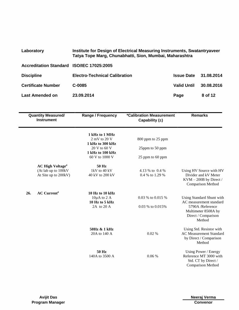
1 kHz to 1 MHz
2 mV to 20 V
800 ppm to 25 ppm
1 kHz to 300 kHz
20 V to 60 V
25ppm to 50 ppm
1 kHz to 100 kHz
60 V to 1000 V
25 ppm to 60 ppm
AC High Voltage#
(At lab up to 100kV
At Site up to 200kV)
50 Hz
1kV to 40 kV
40 kV to 200 kV
4.13 % to 0.4 %
0.4 % to 1.29 %
Using HV Source with HV
Divider and kV Meter
KVM – 200B by Direct /
Comparison Method
26. AC Current#
10 Hz to 10 kHz
10µA to 2 A
0.03 % to 0.015 %
Using Standard Shunt with
AC measurement standard
5790A /Reference
Multimeter 8508A by
Direct / Comparison
Method
10 Hz to 5 kHz
2A to 20 A
0.03 % to 0.015%
50Hz & 1 kHz
20A to 140 A
0.02 %
Using Std. Resistor with
AC Measurement Standard
by Direct / Comparison
Method
50 Hz
140A to 3500 A
0.06 %
Using Power / Energy
Reference MT 3000 with
Std. CT by Direct /
Comparison Method
Laboratory Institute for Design of Electrical Measuring Instruments, Swatantryaveer Tatya Tope Marg, Chunabhatti, Sion, Mumbai, Maharashtra
Accreditation Standard ISO/IEC 17025:2005
Discipline Electro-Technical Calibration
Issue Date 31.08.2014
Certificate Number C-0085
Valid Until 30.08.2016
Last Amended on
23.09.2014
Page 9 of 12
Quantity Measured/ Instrument
Range / Frequency *Calibration Measurement
Capability ()
Remarks
Avijit Das
Neeraj Verma
Program Manager Convenor
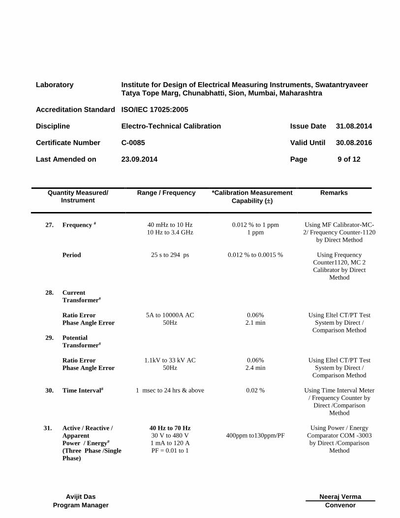
27. Frequency #
Period
40 mHz to 10 Hz
10 Hz to 3.4 GHz
25 s to 294 ps
0.012 % to 1 ppm
1 ppm
0.012 % to 0.0015 %
Using MF Calibrator-MC-
2/ Frequency Counter-1120
by Direct Method
Using Frequency
Counter1120, MC 2
Calibrator by Direct
Method
28. Current
Transformer#
Ratio Error
Phase Angle Error
5A to 10000A AC
50Hz
0.06%
2.1 min
Using Eltel CT/PT Test
System by Direct /
Comparison Method
29. Potential
Transformer#
Ratio Error
Phase Angle Error
1.1kV to 33 kV AC
50Hz
0.06%
2.4 min
Using Eltel CT/PT Test
System by Direct /
Comparison Method
30. Time Interval#
1 msec to 24 hrs & above 0.02 % Using Time Interval Meter
/ Frequency Counter by
Direct /Comparison
Method
31. Active / Reactive /
Apparent
Power / Energy#
(Three Phase /Single
Phase)
40 Hz to 70 Hz
30 V to 480 V
1 mA to 120 A
PF = 0.01 to 1
400ppm to130ppm/PF
Using Power / Energy
Comparator COM -3003
by Direct /Comparison
Method

Laboratory Institute for Design of Electrical Measuring Instruments, Swatantryaveer Tatya Tope Marg, Chunabhatti, Sion, Mumbai, Maharashtra
Accreditation Standard ISO/IEC 17025:2005
Discipline Electro-Technical Calibration
Issue Date 31.08.2014
Certificate Number C-0085
Valid Until 30.08.2016
Last Amended on
23.09.2014
Page 10 of 12
Quantity Measured/ Instrument
Range / Frequency *Calibration Measurement
Capability ()
Remarks
Avijit Das
Neeraj Verma
Program Manager Convenor
40 Hz to 70Hz
40 V to 480 V
120 A to 300 A
PF = 0.01 to 1
0.03% to 0.25% / PF
Using Power / Energy Test
System , MT 3000 by
Direct /Comparison
Method
32. Power Factor
Phase Angle#
50 Hz
0 to UNITY PF
(0 to 360°)
30V to 320 V,
1 mA to 120 A
0.008°
Using Power / Energy
Comparator COM -3003
by Direct /Comparison
Method
33. Capacitance#
1 kHz
10 pF to 1 nF
1 nF to 100 uF
100 uF to 100 mF
0.6 %
0.6 % to 0.06 %
0.06% to 0.6 %
Using RLC DigiBridge,
1689 by Direct
/Comparison Method
100 Hz
1 uF to 1 mF
1 mF to 10 mF
0.12 % to 0.3 %
0.3 % to 1.4 %
34. Inductance#
1 kHz
100 µH to 100 mH
100 mH to 10 H
0.26% to 0.04 %
0.04% to 0.06 %
Using RLC DigiBridge,
1689 by Direct
/Comparison Method
35. AC Resistance#
1 kHz
100 mΩ to 1 Ω
1 Ω to 10 k Ω
10 kΩ to 10 MΩ
50 Hz
0.1 Ω to 1 MΩ
0.83% to 0.1 %
0.1% to 0.05 %
0.05% to 0.3 %
0.3 to 0.6 %
Using RLC DigiBridge,
1689 by Direct
/Comparison Method
Laboratory Institute for Design of Electrical Measuring Instruments, Swatantryaveer Tatya Tope Marg, Chunabhatti, Sion, Mumbai, Maharashtra
Accreditation Standard ISO/IEC 17025:2005
Discipline Electro-Technical Calibration
Issue Date 31.08.2014
Certificate Number C-0085
Valid Until 30.08.2016
Last Amended on
23.09.2014
Page 11 of 12
Quantity Measured/ Instrument
Range / Frequency *Calibration Measurement
Capability ()
Remarks
Avijit Das
Neeraj Verma
Program Manager Convenor
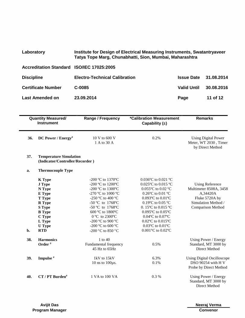
36. DC Power / Energy#
10 V to 600 V
1 A to 30 A
0.2% Using Digital Power
Meter, WT 2030 , Timer
by Direct Method
37. Temperature Simulation
(Indicator/Controller/Recorder )
a. Thermocouple Type
K Type -200 ºC to 1370ºC 0.036ºC to 0.021 ºC
Using Reference
Multimeter 8508A, 3458
A,34420A
Fluke 5720A by
Simulation Method /
Comparison Method
J Type -200 ºC to 1200ºC 0.025ºC to 0.015 ºC
N Type -200 ºC to 1300ºC 0.055ºC to 0.02 ºC
E Type -270 ºC to 1000 ºC 0.26ºC to 0.01 ºC
T Type -250 ºC to 400 ºC 0.093ºC to 0.01ºC
R Type -50 ºC to 1768ºC 0.19ºC to 0.05 ºC
S Type -50 ºC to 1768ºC 0. 15ºC to 0.015 ºC
B Type 600 ºC to 1800ºC 0.095ºC to 0.05ºC
C Type 0 ºC to 2300ºC 0.04ºC to 0.07ºC
L Type -200 ºC to 900 ºC 0.02ºC to 0.015ºC
U Type -200 ºC to 600 ºC 0.03ºC to 0.01ºC
b. RTD
-200 C to 850 C 0.001°C to 0.02ºC
38. Harmonics
Order #
1 to 40
Fundamental frequency
45 Hz to 65Hz
0.5%
Using Power / Energy
Standard, MT 3000 by
Direct Method
39. Impulse #
1kV to 15kV
10 ns to 100µs.
6.3%
0.1%
Using Digital Oscilloscope
DSO 90254 with H V
Probe by Direct Method
40. CT / PT Burden#
1 VA to 100 VA 0.3 % Using Power / Energy
Standard, MT 3000 by
Direct Method
Laboratory Institute for Design of Electrical Measuring Instruments, Swatantryaveer Tatya Tope Marg, Chunabhatti, Sion, Mumbai, Maharashtra
Accreditation Standard ISO/IEC 17025:2005
Discipline Electro-Technical Calibration
Issue Date 31.08.2014
Certificate Number C-0085
Valid Until 30.08.2016
Last Amended on
23.09.2014
Page 12 of 12
Quantity Measured/ Instrument
Range / Frequency *Calibration Measurement
Capability ()
Remarks
Avijit Das
Neeraj Verma
Program Manager Convenor
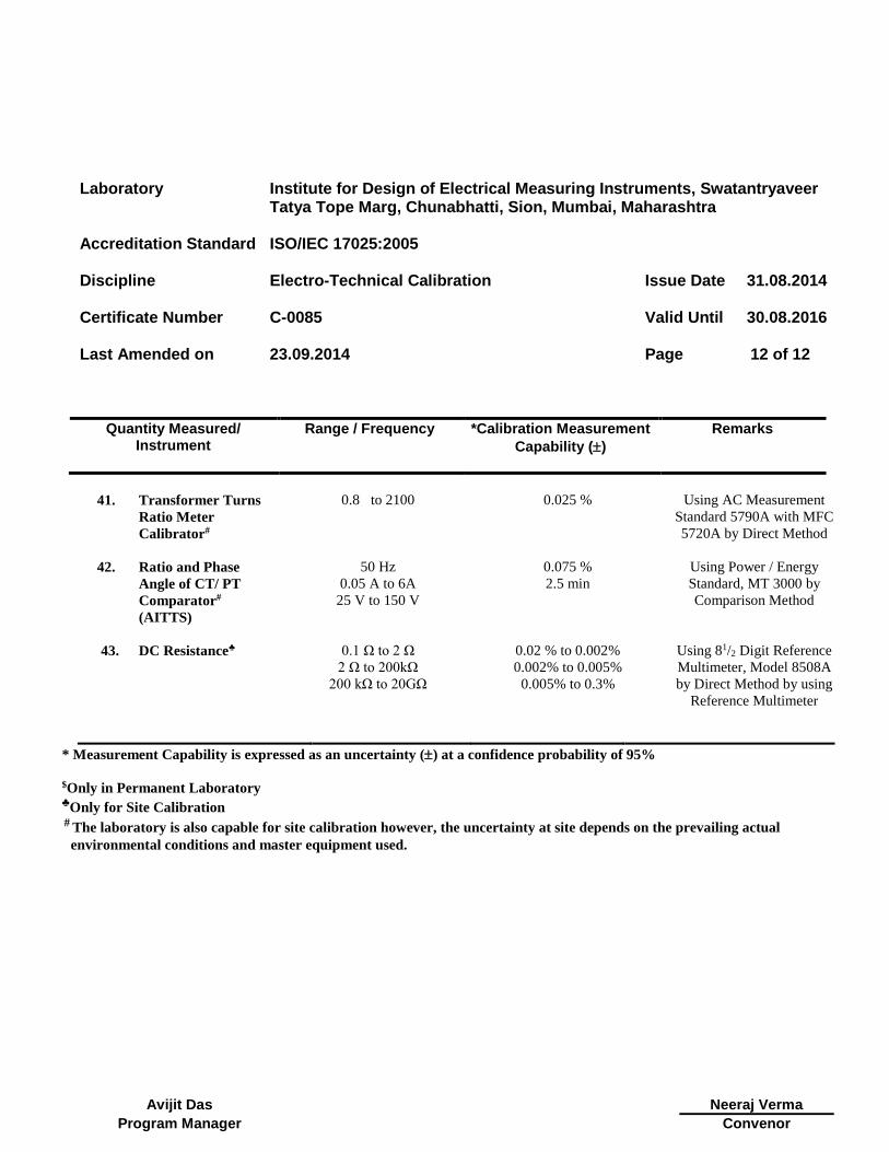
41. Transformer Turns
Ratio Meter
Calibrator#
0.8 to 2100 0.025 % Using AC Measurement
Standard 5790A with MFC
5720A by Direct Method
42. Ratio and Phase
Angle of CT/ PT
Comparator#
(AITTS)
50 Hz
0.05 A to 6A
25 V to 150 V
0.075 %
2.5 min
Using Power / Energy
Standard, MT 3000 by
Comparison Method
43. DC Resistance♣
0.1 Ω to 2 Ω 0.02 % to 0.002% Using 81/2 Digit Reference
Multimeter, Model 8508A
by Direct Method by using
Reference Multimeter
2 Ω to 200kΩ 0.002% to 0.005%
200 kΩ to 20GΩ 0.005% to 0.3%
* Measurement Capability is expressed as an uncertainty () at a confidence probability of 95%
$Only in Permanent Laboratory ♣Only for Site Calibration # The laboratory is also capable for site calibration however, the uncertainty at site depends on the prevailing actual
environmental conditions and master equipment used.