

γλώσσες
Σελίδες
Νομικός

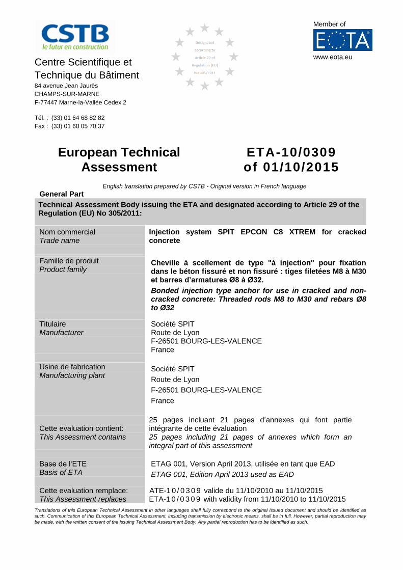
Centre Scientifique et
Technique du Bâtiment 84 avenue Jean Jaurès
CHAMPS-SUR-MARNE
F-77447 Marne-la-Vallée Cedex 2
Tél. : (33) 01 64 68 82 82
Fax : (33) 01 60 05 70 37
Member of
www.eota.eu
European Technical Assessment
ETA-10/0309 of 01/10/2015
English translation prepared by CSTB - Original version in French language
General Part
Technical Assessment Body issuing the ETA and designated according to Article 29 of the Regulation (EU) No 305/2011:
Nom commercial Trade name
Injection system SPIT EPCON C8 XTREM for cracked concrete
Famille de produit Product family
Cheville à scellement de type "à injection" pour fixation dans le béton fissuré et non fissuré : tiges filetées M8 à M30 et barres d’armatures Ø8 à Ø32.
Bonded injection type anchor for use in cracked and non- cracked concrete: Threaded rods M8 to M30 and rebars Ø8 to Ø32
Titulaire Manufacturer
Société SPIT Route de Lyon F-26501 BOURG-LES-VALENCE France
Usine de fabrication Manufacturing plant
Société SPIT
Route de Lyon
F-26501 BOURG-LES-VALENCE
France
Cette evaluation contient: This Assessment contains
25 pages incluant 21 pages d’annexes qui font partie intégrante de cette évaluation 25 pages including 21 pages of annexes which form an integral part of this assessment
Base de l‘ETE Basis of ETA
ETAG 001, Version April 2013, utilisée en tant que EAD
ETAG 001, Edition April 2013 used as EAD
Cette evaluation remplace: This Assessment replaces
ATE-1 0 / 0 3 0 9 valide du 11/10/2010 au 11/10/2015 ETA-1 0 / 0 3 0 9 with validity from 11/10/2010 to 11/10/2015
Translations of this European Technical Assessment in other languages shall fully correspond to the original issued document and should be identified as
such. Communication of this European Technical Assessment, including transmission by electronic means, shall be in full. However, partial reproduction may
be made, with the written consent of the issuing Technical Assessment Body. Any partial reproduction has to be identified as such.
European technical assessment ETA-1 0 / 0 3 0 9
English translation prepared by CSTB
Page 2 of 25 | 0 1 / 1 0 / 2 0 1 5
Specific part
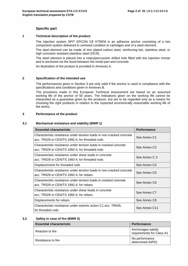
1 Technical description of the product
The Injection system SPIT EPCON C8 XTREM is an adhesive anchor consisting of a two component system delivered in unmixed condition in cartridges and of a steel element.
The steel element can be made of zinc plated carbon steel, reinforcing bar, stainless steel, or high corrosion resistant stainless steel (HCR).
The steel element is placed into a rotary/percussion drilled hole filled with the injection mortar and is anchored via the bond between the metal part and concrete.
An illustration of the product is provided in Annexes A.
2 Specification of the intended use
The performances given in Section 3 are only valid if the anchor is used in compliance with the specifications and conditions given in Annexes B.
The provisions made in this European Technical Assessment are based on an assumed working life of the anchor of 50 years. The indications given on the working life cannot be interpreted as a guarantee given by the producer, but are to be regarded only as a means for choosing the right products in relation to the expected economically reasonable working life of the works.
3 Performance of the product
3.1 Mechanical resistance and stability (BWR 1)
Essential characteristic Performance
Characteristic resistance under tension loads in non-cracked concrete
acc. TR029 or CEN/TS 1992-4, for threaded rods See Annex C1
Characteristic resistance under tension loads in cracked concrete
acc. TR029 or CEN/TS 1992-4, for threaded rods See Annex C2
Characteristic resistance under shear loads in concrete
acc. TR029 or CEN/TS 1992-4, for threaded rods See Annex C 3
Displacements for threaded rods See Annex C4
Characteristic resistance under tension loads in non-cracked concrete
acc. TR029 or CEN/TS 1992-4, for rebars See Annex C5
Characteristic resistance under tension loads in cracked concrete
acc. TR029 or CEN/TS 1992-4, for rebars See Annex C6
Characteristic resistance under shear loads in concrete
acc. TR029 or CEN/TS 1992-4, for rebars See Annex C7
Displacements for rebars See Annex C8
Characteristic resistance under seismic action C1 acc. TR045,
for threaded rods See Annex C11
3.2 Safety in case of fire (BWR 2)
Essential characteristic Performance
Reaction to fire Anchorages satisfy requirements for Class A1
Resistance to fire No performance determined (NPD)
European technical assessment ETA-1 0 / 0 3 0 9
English translation prepared by CSTB
Page 3 of 25 | 0 1 / 1 0 / 2 0 1 5
3.3 Hygiene, health and the environment (BWR 3)
Regarding dangerous substances contained in this European Technical Assessment, there may be requirements applicable to the products falling within its scope (e.g. transposed European legislation and national laws, regulations and administrative provisions). In order to meet the provisions of the Construction Products Directive, these requirements need also to be complied with, when and where they apply.
3.4 Safety in use (BWR 4)
For Basic requirement Safety in use the same criteria are valid as for Basic Requirement Mechanical resistance and stability.
3.5 Protection against noise (BWR 5)
Not relevant.
3.6 Energy economy and heat retention (BWR 6)
Not relevant.
3.7 Sustainable use of natural resources ( (BWR 7)
For the sustainable use of natural resources no performance was determined for this product.
3.8 General aspects relating to fitness for use
Durability and Serviceability are only ensured if the specifications of intended use according to Annex B1 are kept.
4 Assessment and verification of constancy of performance (AVCP)
According to the Decision 96/582/EC of the European Commission 1, as amended, the system of assessment and verification of constancy of performance (see Annex V to Regulation (EU) No 305/2011) given in the following table apply.
Product Intended use Level or class System
Metal anchors for use in concrete
For fixing and/or supporting to concrete, structural elements (which contributes to the stability of the works) or heavy units
― 1
5 Technical details necessary for the implementation of the AVCP system
Technical details necessary for the implementation of the Assessment and verification of constancy of performance (AVCP) system are laid down in the control plan deposited at Centre Scientifique et Technique du Bâtiment.
The manufacturer shall, on the basis of a contract, involve a notified body approved in the field of anchors for issuing the certificate of conformity CE based on the control plan.
The original French version is signed by
Charles Baloche
Technical Director
1 Official Journal of the European Communities L 254 of 08.10.1996
European technical assessment ETA-1 0 / 0 3 0 9
English translation prepared by CSTB
Page 4 of 25 | 0 1 / 1 0 / 2 0 1 5
SPIT EPCON C8 XTREM
Product description
Mortar cartridges
Annex A1
Injection mortar
Two component epoxy system
Marking
Identifying mark of the producer SPIT Expire date
Trade name EPCON C8 XTREM Curing and processing time Charge code number
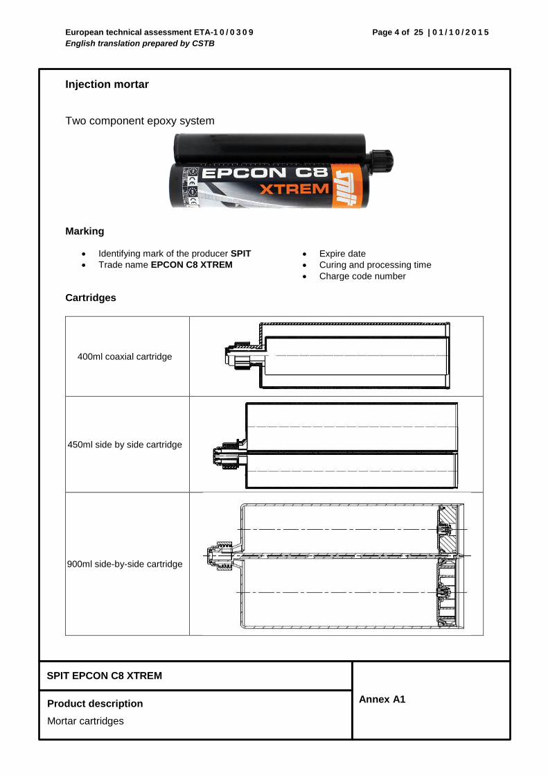
Cartridges
400ml coaxial cartridge
450ml side by side cartridge
900ml side-by-side cartridge
European technical assessment ETA-1 0 / 0 3 0 9
English translation prepared by CSTB
Page 5 of 25 | 0 1 / 1 0 / 2 0 1 5
SPIT EPCON C8 XTREM
Product description
Mixing nozzles, extensions and dispensers
Annex A2
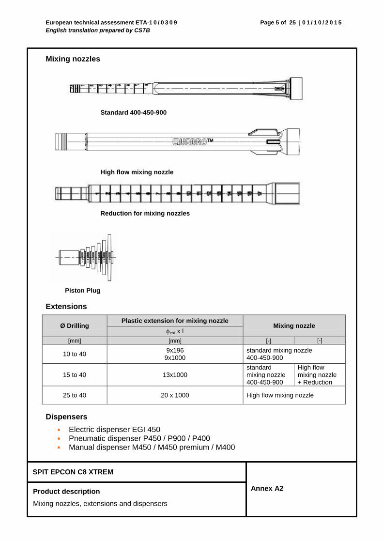
Mixing nozzles
Standard 400-450-900
High flow mixing nozzle
Reduction for mixing nozzles
Piston Plug
Extensions
Ø Drilling Plastic extension for mixing nozzle
Mixing nozzle ext x l
[mm] [mm] [-] [-]
10 to 40 9x196
9x1000 standard mixing nozzle 400-450-900
15 to 40 13x1000 standard mixing nozzle 400-450-900
High flow mixing nozzle + Reduction
25 to 40 20 x 1000 High flow mixing nozzle
Dispensers
Electric dispenser EGI 450 Pneumatic dispenser P450 / P900 / P400 Manual dispenser M450 / M450 premium / M400
European technical assessment ETA-1 0 / 0 3 0 9
English translation prepared by CSTB
Page 6 of 25 | 0 1 / 1 0 / 2 0 1 5
SPIT EPCON C8 XTREM
Product description
Steel elements
Annex A3
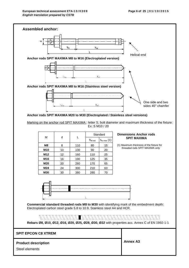
Assembled anchor:
Helical end Anchor rods SPIT MAXIMA M8 to M16 (Electroplated version)
Anchor rods SPIT MAXIMA M8 to M16 (Stainless steel version)
Anchor rods SPIT MAXIMA M20 to M30 (Electroplated / Stainless steel versions)
Marking on the anchor rod SPIT MAXIMA : letter S, bolt diameter and maximum thickness of the fixture:
Ex: S M10 / 20
M d L Standard
hef,std tfix max (1)
M8 8 110 80 15
M10
10 130 90 20
M12
12 160 110 25
M16 16 190 125 35
M20
20 260 170 65
M24
24 300 210 63
M30
30 380 280 70
Commercial standard threaded rods M8 to M30 with identifying mark of the embedment depth: Electroplated carbon steel grade 5.8 to 10.9, Stainless steel A4 and HCR.
Rebars Ø8, Ø10, Ø12, Ø16, Ø20, Ø25, Ø28, Ø30, Ø32 with properties acc. Annex C of EN 1992-1-1
One side and two sides 45° chamfer
Dimensions Anchor rods SPIT MAXIMA
(1) Maximum thickness of the fixture for threaded rods SPIT MAXIMA only
European technical assessment ETA-1 0 / 0 3 0 9
English translation prepared by CSTB
Page 7 of 25 | 0 1 / 1 0 / 2 0 1 5
SPIT EPCON C8 XTREM
Product description
Materials, threaded rods
Annex A4
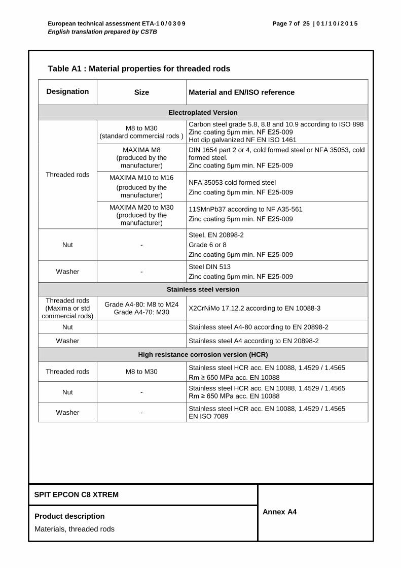
Table A1 : Material properties for threaded rods
Designation Size Material and EN/ISO reference
Electroplated Version
Threaded rods
M8 to M30 (standard commercial rods )
Carbon steel grade 5.8, 8.8 and 10.9 according to ISO 898 Zinc coating 5μm min. NF E25-009 Hot dip galvanized NF EN ISO 1461
MAXIMA M8 (produced by the
manufacturer)
DIN 1654 part 2 or 4, cold formed steel or NFA 35053, cold formed steel. Zinc coating 5μm min. NF E25-009
MAXIMA M10 to M16
(produced by the manufacturer)
NFA 35053 cold formed steel
Zinc coating 5μm min. NF E25-009
MAXIMA M20 to M30 (produced by the
manufacturer)
11SMnPb37 according to NF A35-561
Zinc coating 5μm min. NF E25-009
Nut -
Steel, EN 20898-2
Grade 6 or 8
Zinc coating 5μm min. NF E25-009
Washer - Steel DIN 513
Zinc coating 5μm min. NF E25-009
Stainless steel version
Threaded rods (Maxima or std
commercial rods)
Grade A4-80: M8 to M24 Grade A4-70: M30
X2CrNiMo 17.12.2 according to EN 10088-3
Nut Stainless steel A4-80 according to EN 20898-2
Washer Stainless steel A4 according to EN 20898-2
High resistance corrosion version (HCR)
Threaded rods M8 to M30 Stainless steel HCR acc. EN 10088, 1.4529 / 1.4565
Rm ≥ 650 MPa acc. EN 10088
Nut - Stainless steel HCR acc. EN 10088, 1.4529 / 1.4565 Rm ≥ 650 MPa acc. EN 10088
Washer - Stainless steel HCR acc. EN 10088, 1.4529 / 1.4565 EN ISO 7089
European technical assessment ETA-1 0 / 0 3 0 9
English translation prepared by CSTB
Page 8 of 25 | 0 1 / 1 0 / 2 0 1 5
SPIT EPCON C8 XTREM
Product description
Rebars
Annex A5
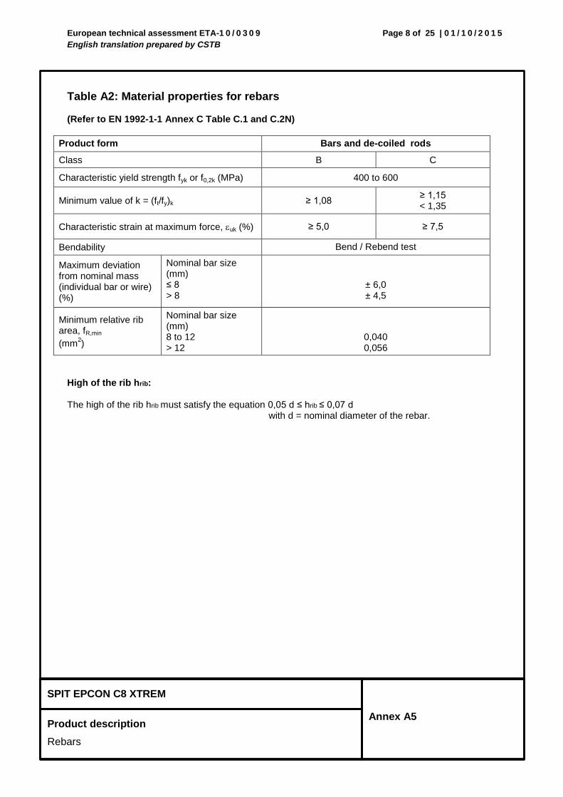
Table A2: Material properties for rebars (Refer to EN 1992-1-1 Annex C Table C.1 and C.2N)
Product form Bars and de-coiled rods
Class B C
Characteristic yield strength fyk or f0,2k (MPa) 400 to 600
Minimum value of k = (ft/fy)k ≥ 1,08 ≥ 1,15 < 1,35
Characteristic strain at maximum force, uk (%) ≥ 5,0 ≥ 7,5
Bendability Bend / Rebend test
Maximum deviation from nominal mass (individual bar or wire) (%)
Nominal bar size (mm) ≤ 8 > 8
± 6,0 ± 4,5
Minimum relative rib area, fR,min
(mm2)
Nominal bar size (mm) 8 to 12 > 12
0,040 0,056
High of the rib hrib: The high of the rib hrib must satisfy the equation 0,05 d ≤ hrib ≤ 0,07 d
with d = nominal diameter of the rebar.
European technical assessment ETA-1 0 / 0 3 0 9
English translation prepared by CSTB
Page 9 of 25 | 0 1 / 1 0 / 2 0 1 5
SPIT EPCON C8 XTREM
Intended Use
Specifications
Annex B1
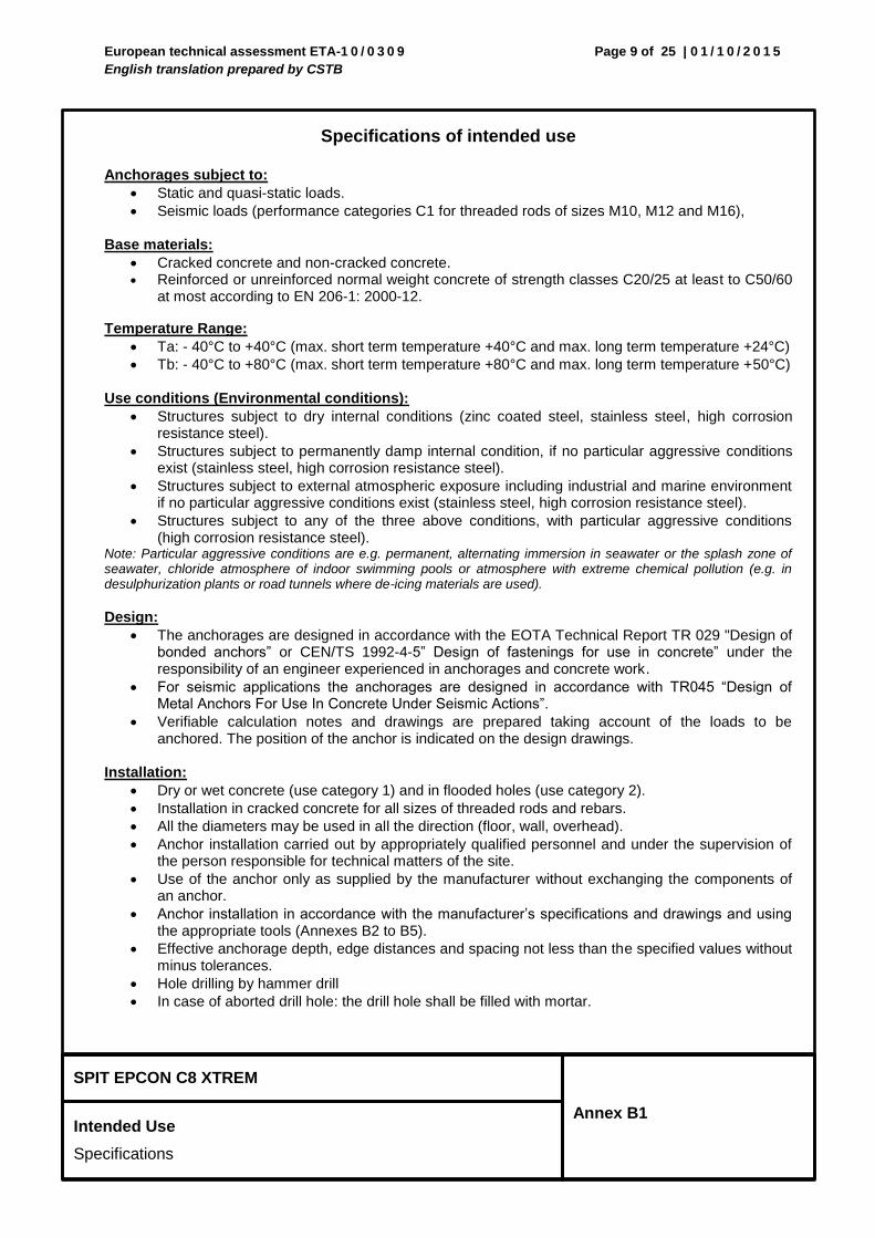
Specifications of intended use
Anchorages subject to:
Static and quasi-static loads.
Seismic loads (performance categories C1 for threaded rods of sizes M10, M12 and M16),
Base materials:
Cracked concrete and non-cracked concrete. Reinforced or unreinforced normal weight concrete of strength classes C20/25 at least to C50/60
at most according to EN 206-1: 2000-12.
Temperature Range:
Ta: - 40°C to +40°C (max. short term temperature +40°C and max. long term temperature +24°C)
Tb: - 40°C to +80°C (max. short term temperature +80°C and max. long term temperature +50°C)
Use conditions (Environmental conditions):
Structures subject to dry internal conditions (zinc coated steel, stainless steel, high corrosion resistance steel).
Structures subject to permanently damp internal condition, if no particular aggressive conditions exist (stainless steel, high corrosion resistance steel).
Structures subject to external atmospheric exposure including industrial and marine environment if no particular aggressive conditions exist (stainless steel, high corrosion resistance steel).
Structures subject to any of the three above conditions, with particular aggressive conditions (high corrosion resistance steel).
Note: Particular aggressive conditions are e.g. permanent, alternating immersion in seawater or the splash zone of seawater, chloride atmosphere of indoor swimming pools or atmosphere with extreme chemical pollution (e.g. in desulphurization plants or road tunnels where de-icing materials are used).
Design:
The anchorages are designed in accordance with the EOTA Technical Report TR 029 "Design of bonded anchors” or CEN/TS 1992-4-5” Design of fastenings for use in concrete” under the responsibility of an engineer experienced in anchorages and concrete work.
For seismic applications the anchorages are designed in accordance with TR045 “Design of Metal Anchors For Use In Concrete Under Seismic Actions”.
Verifiable calculation notes and drawings are prepared taking account of the loads to be anchored. The position of the anchor is indicated on the design drawings.
Installation:
Dry or wet concrete (use category 1) and in flooded holes (use category 2).
Installation in cracked concrete for all sizes of threaded rods and rebars.
All the diameters may be used in all the direction (floor, wall, overhead).
Anchor installation carried out by appropriately qualified personnel and under the supervision of the person responsible for technical matters of the site.
Use of the anchor only as supplied by the manufacturer without exchanging the components of an anchor.
Anchor installation in accordance with the manufacturer’s specifications and drawings and using the appropriate tools (Annexes B2 to B5).
Effective anchorage depth, edge distances and spacing not less than the specified values without minus tolerances.
Hole drilling by hammer drill
In case of aborted drill hole: the drill hole shall be filled with mortar.
European technical assessment ETA-1 0 / 0 3 0 9
English translation prepared by CSTB
Page 10 of 25 | 0 1 / 1 0 / 2 0 1 5
SPIT EPCON C8 XTREM
Intended Use
Specifications
Annex B1
For overhead installation, piston plugs shall be used, embedded metal parts shall be fixed during the curing time, e.g. with wedges.
Note:
Rebars may be used as anchor designed in accordance with the EOTA Technical Report TR 029 only. The basic assumptions for the design according to anchor theory shall be observed. This includes the consideration of tension and shear loads and the corresponding failure modes as well as the assumption that the base material (concrete structural element) remains essentially in the serviceability limit state (either non-cracked or cracked) when the connection is loaded to failure. Such applications are e.g. concrete overlay or shear dowel connections or the connections of a wall predominantly loaded by shear and compression forces with the foundation, where the rebars act as dowels to take up shear forces.
European technical assessment ETA-1 0 / 0 3 0 9
English translation prepared by CSTB
Page 11 of 25 | 0 1 / 1 0 / 2 0 1 5
SPIT EPCON C8 XTREM
Intended Use
Installation data for threaded rods
Annex B2
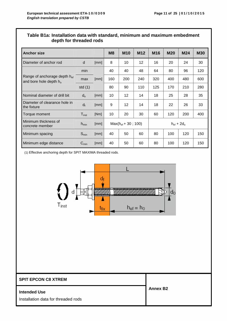
Table B1a: Installation data with standard, minimum and maximum embedment
depth for threaded rods
Anchor size M8 M10 M12 M16 M20 M24 M30
Diameter of anchor rod d [mm] 8 10 12 16 20 24 30
Range of anchorage depth hef
and bore hole depth ho
min
[mm]
40 40 48 64 80 96 120
max 160 200 240 320 400 480 600
std (1) 80 90 110 125 170 210 280
Nominal diameter of drill bit do [mm] 10 12 14 18 25 28 35
Diameter of clearance hole in the fixture
df [mm] 9 12 14 18 22 26 33
Torque moment Tinst [Nm] 10 20 30 60 120 200 400
Minimum thickness of concrete member
hmin [mm] Max(hef + 30 ; 100) hef + 2do
Minimum spacing Smin [mm] 40 50 60 80 100 120 150
Minimum edge distance Cmin [mm] 40 50 60 80 100 120 150
(1) Effective anchoring depth for SPIT MAXIMA threaded rods.
European technical assessment ETA-1 0 / 0 3 0 9
English translation prepared by CSTB
Page 12 of 25 | 0 1 / 1 0 / 2 0 1 5
SPIT EPCON C8 XTREM
Intended Use
Installation data for rebars
Annex B3
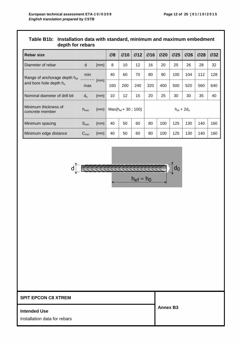
Table B1b: Installation data with standard, minimum and maximum embedment depth for rebars
Rebar size Ø8 Ø10 Ø12 Ø16 Ø20 Ø25 Ø26 Ø28 Ø32
Diameter of rebar d [mm] 8 10 12 16 20 25 26 28 32
Range of anchorage depth hef
and bore hole depth ho
min
[mm]
40 60 70 80 90 100 104 112 128
max 160 200 240 320 400 500 520 560 640
Nominal diameter of drill bit do [mm] 10 12 15 20 25 30 30 35 40
Minimum thickness of concrete member
hmin [mm] Max(hef + 30 ; 100) hef + 2do
Minimum spacing Smin [mm] 40 50 60 80 100 125 130 140 160
Minimum edge distance Cmin [mm] 40 50 60 80 100 125 130 140 160
European technical assessment ETA-1 0 / 0 3 0 9
English translation prepared by CSTB
Page 13 of 25 | 0 1 / 1 0 / 2 0 1 5
SPIT EPCON C8 XTREM
Intended Use
Cleaning tools, curing time
Annex B4
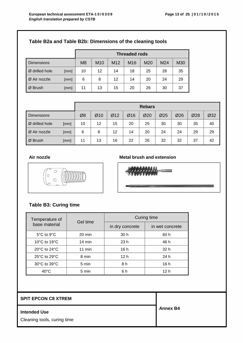
Table B2a and Table B2b: Dimensions of the cleaning tools
Threaded rods
Dimensions M8 M10 M12 M16 M20 M24 M30
Ø drilled hole [mm] 10 12 14 18 25 28 35
Ø Air nozzle [mm] 6 8 12 14 20 24 29
Ø Brush [mm] 11 13 15 20 26 30 37
Rebars
Dimensions Ø8 Ø10 Ø12 Ø16 Ø20 Ø25 Ø26 Ø28 Ø32
Ø drilled hole [mm] 10 12 15 20 25 30 30 35 40
Ø Air nozzle [mm] 6 8 12 14 20 24 24 29 29
Ø Brush [mm] 11 13 16 22 26 32 32 37 42
Air nozzle Metal brush and extension
Table B3: Curing time
Temperature of base material
Gel time Curing time
in dry concrete in wet concrete
5°C to 9°C 20 min 30 h 60 h
10°C to 19°C 14 min 23 h 46 h
20°C to 24°C 11 min 16 h 32 h
25°C to 29°C 8 min 12 h 24 h
30°C to 39°C 5 min 8 h 16 h
40°C 5 min 6 h 12 h
European technical assessment ETA-1 0 / 0 3 0 9
English translation prepared by CSTB
Page 14 of 25 | 0 1 / 1 0 / 2 0 1 5
SPIT EPCON C8 XTREM
Intended Use
Installation instructions
Annex B5
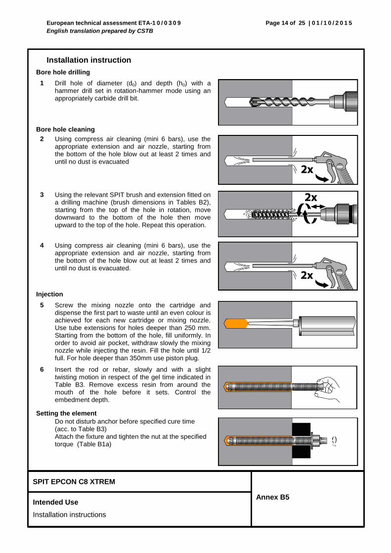
Installation instruction
Bore hole drilling
1 Drill hole of diameter (d0) and depth (h0) with a hammer drill set in rotation-hammer mode using an appropriately carbide drill bit.
Bore hole cleaning
2 Using compress air cleaning (mini 6 bars), use the appropriate extension and air nozzle, starting from the bottom of the hole blow out at least 2 times and until no dust is evacuated
3 Using the relevant SPIT brush and extension fitted on a drilling machine (brush dimensions in Tables B2), starting from the top of the hole in rotation, move downward to the bottom of the hole then move upward to the top of the hole. Repeat this operation.
4 Using compress air cleaning (mini 6 bars), use the appropriate extension and air nozzle, starting from the bottom of the hole blow out at least 2 times and until no dust is evacuated.
Injection
5 Screw the mixing nozzle onto the cartridge and dispense the first part to waste until an even colour is achieved for each new cartridge or mixing nozzle. Use tube extensions for holes deeper than 250 mm. Starting from the bottom of the hole, fill uniformly. In order to avoid air pocket, withdraw slowly the mixing nozzle while injecting the resin. Fill the hole until 1/2 full. For hole deeper than 350mm use piston plug.
6 Insert the rod or rebar, slowly and with a slight twisting motion in respect of the gel time indicated in Table B3. Remove excess resin from around the mouth of the hole before it sets. Control the embedment depth.
Setting the element
Do not disturb anchor before specified cure time (acc. to Table B3) Attach the fixture and tighten the nut at the specified torque (Table B1a)
European technical assessment ETA-1 0 / 0 3 0 9
English translation prepared by CSTB
Page 15 of 25 | 0 1 / 1 0 / 2 0 1 5
SPIT EPCON C8 XTREM
Design according to TR 029 or CEN/TS 1992-4
Characteristic values for tension loads in non-cracked concrete for threaded rods
Annex C1
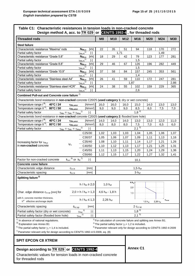
Table C1: Characteristic resistances in tension loads in non-cracked concrete
Design method A, acc. to TR 029 or CEN/TS 1992-4 , for threaded rods
Threaded rods M8 M10 M12 M16 M20 M24 M30
Steel failure
Characteristic resistance “Maxima” rods NRk,s [kN] 22 35 51 94 118 170 272
Partial safety factor Ms,N1)
[-] 1,71 1,49
Characteristic resistance “Grade 5.8” NRk,s [kN] 18 29 42 79 123 177 281
Partial safety factor Ms,N1)
[-] 1,5
Characteristic resistance “Grade 8.8” NRk,s [kN] 29 46 67 126 196 282 449
Partial safety factor Ms,N1) [-] 1,5
Characteristic resistance “Grade 10.9” NRk,s [kN] 37 58 84 157 245 353 561
Partial safety factor Ms,N1)
[-] 1,4
Characteristic resistance “Stainless steel A4” NRk,s [kN] 26 41 59 110 172 247 281
Partial safety factor Ms,N1)
[-] 1,87 2,86
Characteristic resistance “Stainless steel HCR” NRk,s [kN] 24 38 55 102 159 229 365
Partial safety factor Ms,N1) [-] 2,6
Combined Pull-out and Concrete cone failure 2)
Characteristic bond resistance in non-cracked concrete C20/25 (used category 1: dry or wet concrete)
Temperature range I 3)
: 40°C / 24°C Rk,uncr [N/mm²] 16,0 16,0 16,0 15,0 14,0 13,0 13,0
Temperature range II 3)
: 80°C / 50°C Rk,uncr [N/mm²] 9,0 9,0 9,0 8,5 8,0 7,5 7,0
Partial safety factor Mp =Mc =Msp1) [-] 1,8
4)
Characteristic bond resistance in non-cracked concrete C20/25 (used category 2: flooded bore hole)
Temperature range I 3)
: 40°C / 24°C Rk,uncr [N/mm²] 14,0 14,0 14,0 13,0 13,0 12,0 11,0
Temperature range II 3)
: 80°C / 50°C Rk,uncr [N/mm²] 8,0 8,0 8,0 7,5 7,0 6,5 6,0
Partial safety factor Mp =Mc =Msp1) [-] 2,1
5)
Increasing factor for Rk,p in non-cracked concrete
c
C25/30 1,02 1,03 1,03 1,04 1,05 1,06 1,07
C30/37 1,05 1,06 1,07 1,09 1,11 1,13 1,16
C35/40 1,08 1,10 1,11 1,14 1,17 1,21 1,26
C40/50 1,10 1,12 1,13 1,17 1,21 1,25 1,31
C45/55 1,11 1,13 1,15 1,20 1,24 1,29 1,36
C50/60 1,12 1,15 1,17 1,22 1,27 1,32 1,41
Factor for non-cracked concrete kucr 6)
or k8 7)
[-] 10,1
Concrete cone failure
Characteristic edge distance ccr,N [mm] 1,5·hef
Characteristic spacing scr,N [mm] 3·hef
Splitting failure 2)
Char. edge distance ccr,sp [mm] for
h / hef ≥ 2,0 1,0 hef
2,0 > h / hef > 1,3 4,6 hef - 1,8 h
with h. concrete member thickness,
hef effective anchorage depth
h / hef ≤ 1,3 2,26 hef
Characteristic spacing scr,sp [mm] 2 ccr,sp
Partial safety factor (dry or wet concrete) Msp 1)
[-] 1,8 4)
Partial safety factor (flooded bore hole) Msp 1)
[-] 2,1 5)
1) In absence of national regulations.
2) For calculation of concrete failure and splitting see Annex B1.
3) Explanation see Annex B1 4)
The partial safety factor 2 = 1,2 is included.
5) The partial safety factor 2 = 1,4 is included. 6)
Parameter relevant only for design according to CEN/TS 1992-4:2009 7)
Parameter relevant only for design according to CEN/TS 1992-4-5:2009, eq. (8)
European technical assessment ETA-1 0 / 0 3 0 9
English translation prepared by CSTB
Page 16 of 25 | 0 1 / 1 0 / 2 0 1 5
SPIT EPCON C8 XTREM
Design according to TR 029 or CEN/TS 1992-4
Characteristic values for tension loads in cracked concrete for threaded rods
Annex C2
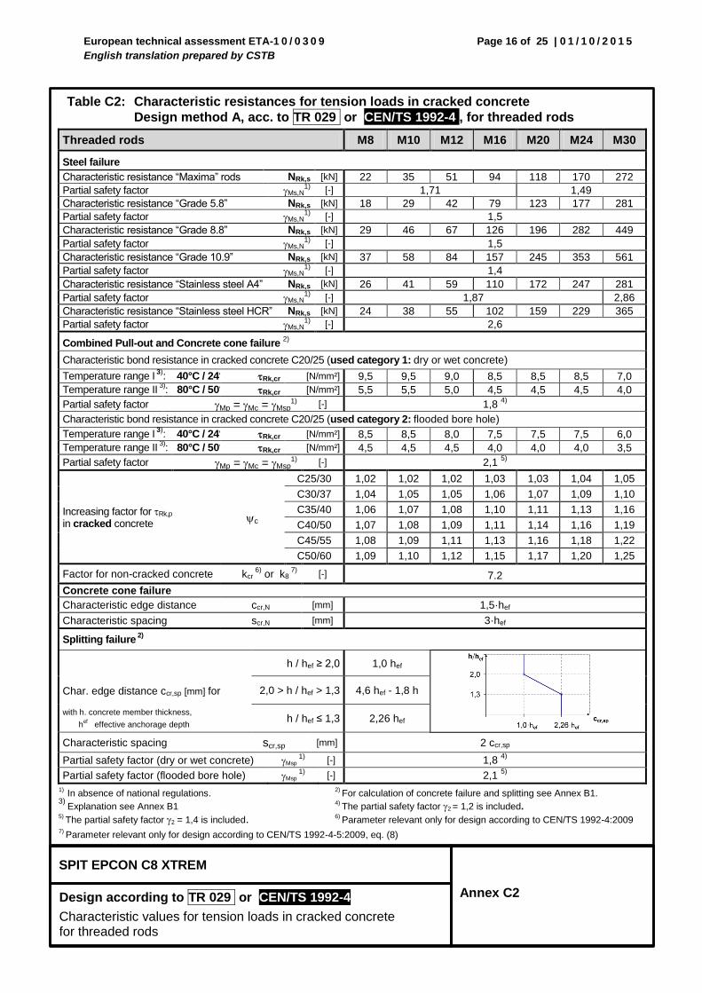
Table C2: Characteristic resistances for tension loads in cracked concrete
Design method A, acc. to TR 029 or CEN/TS 1992-4 , for threaded rods
Threaded rods M8 M10 M12 M16 M20 M24 M30
Steel failure
Characteristic resistance “Maxima” rods NRk,s [kN] 22 35 51 94 118 170 272
Partial safety factor Ms,N1)
[-] 1,71 1,49
Characteristic resistance “Grade 5.8” NRk,s [kN] 18 29 42 79 123 177 281
Partial safety factor Ms,N1)
[-] 1,5
Characteristic resistance “Grade 8.8” NRk,s [kN] 29 46 67 126 196 282 449
Partial safety factor Ms,N1) [-] 1,5
Characteristic resistance “Grade 10.9” NRk,s [kN] 37 58 84 157 245 353 561
Partial safety factor Ms,N1)
[-] 1,4
Characteristic resistance “Stainless steel A4” NRk,s [kN] 26 41 59 110 172 247 281
Partial safety factor Ms,N1)
[-] 1,87 2,86
Characteristic resistance “Stainless steel HCR” NRk,s [kN] 24 38 55 102 159 229 365
Partial safety factor Ms,N1) [-] 2,6
Combined Pull-out and Concrete cone failure 2)
Characteristic bond resistance in cracked concrete C20/25 (used category 1: dry or wet concrete)
Temperature range I 3)
: 40°C / 24°C Rk,cr [N/mm²] 9,5 9,5 9,0 8,5 8,5 8,5 7,0
Temperature range II 3)
: 80°C / 50°C Rk,cr [N/mm²] 5,5 5,5 5,0 4,5 4,5 4,5 4,0
Partial safety factor Mp =Mc =Msp1) [-] 1,8
4)
Characteristic bond resistance in cracked concrete C20/25 (used category 2: flooded bore hole)
Temperature range I 3)
: 40°C / 24°C Rk,cr [N/mm²] 8,5 8,5 8,0 7,5 7,5 7,5 6,0
Temperature range II 3)
: 80°C / 50°C Rk,cr [N/mm²] 4,5 4,5 4,5 4,0 4,0 4,0 3,5
Partial safety factor Mp =Mc =Msp1) [-] 2,1
5)
Increasing factor for Rk,p in cracked concrete
c
C25/30 1,02 1,02 1,02 1,03 1,03 1,04 1,05
C30/37 1,04 1,05 1,05 1,06 1,07 1,09 1,10
C35/40 1,06 1,07 1,08 1,10 1,11 1,13 1,16
C40/50 1,07 1,08 1,09 1,11 1,14 1,16 1,19
C45/55 1,08 1,09 1,11 1,13 1,16 1,18 1,22
C50/60 1,09 1,10 1,12 1,15 1,17 1,20 1,25
Factor for non-cracked concrete kcr 6)
or k8 7)
[-] 7.2
Concrete cone failure
Characteristic edge distance ccr,N [mm] 1,5·hef
Characteristic spacing scr,N [mm] 3·hef
Splitting failure 2)
Char. edge distance ccr,sp [mm] for
h / hef ≥ 2,0 1,0 hef
2,0 > h / hef > 1,3 4,6 hef - 1,8 h
with h. concrete member thickness,
hef effective anchorage depth
h / hef ≤ 1,3 2,26 hef
Characteristic spacing scr,sp [mm] 2 ccr,sp
Partial safety factor (dry or wet concrete) Msp 1)
[-] 1,8 4)
Partial safety factor (flooded bore hole) Msp 1)
[-] 2,1 5)
1) In absence of national regulations.
2) For calculation of concrete failure and splitting see Annex B1.
3) Explanation see Annex B1 4)
The partial safety factor 2 = 1,2 is included.
5) The partial safety factor 2 = 1,4 is included. 6)
Parameter relevant only for design according to CEN/TS 1992-4:2009 7)
Parameter relevant only for design according to CEN/TS 1992-4-5:2009, eq. (8)
European technical assessment ETA-1 0 / 0 3 0 9
English translation prepared by CSTB
Page 17 of 25 | 0 1 / 1 0 / 2 0 1 5
SPIT EPCON C8 XTREM
Design according to TR 029 or CEN/TS 1992-4
Characteristic values for shear loads for threaded rods
Annex C3
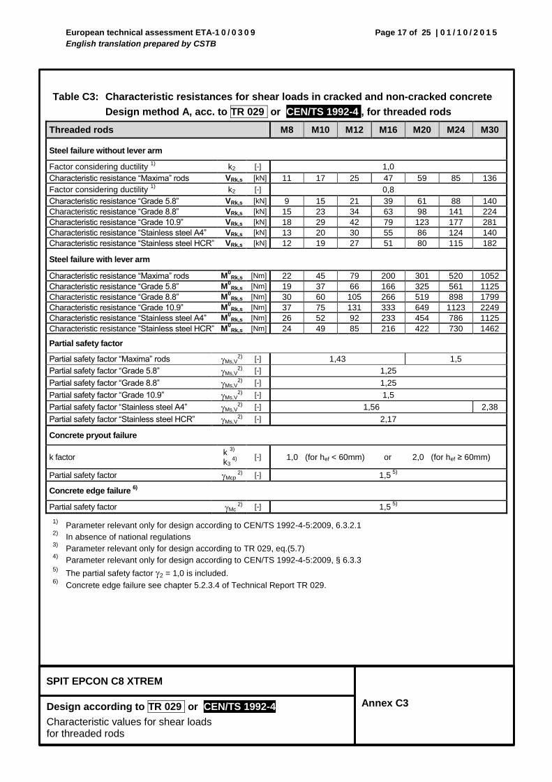
Table C3: Characteristic resistances for shear loads in cracked and non-cracked concrete
Design method A, acc. to TR 029 or CEN/TS 1992-4 , for threaded rods
Threaded rods M8 M10 M12 M16 M20 M24 M30
Steel failure without lever arm
Factor considering ductility 1)
k2 [-] 1,0
Characteristic resistance “Maxima” rods VRk,s [kN] 11 17 25 47 59 85 136
Factor considering ductility 1)
k2 [-] 0,8
Characteristic resistance “Grade 5.8” VRk,s [kN] 9 15 21 39 61 88 140
Characteristic resistance “Grade 8.8” VRk,s [kN] 15 23 34 63 98 141 224
Characteristic resistance “Grade 10.9” VRk,s [kN] 18 29 42 79 123 177 281
Characteristic resistance “Stainless steel A4” VRk,s [kN] 13 20 30 55 86 124 140
Characteristic resistance “Stainless steel HCR” VRk,s [kN] 12 19 27 51 80 115 182
Steel failure with lever arm
Characteristic resistance “Maxima” rods M0
Rk,s [Nm] 22 45 79 200 301 520 1052
Characteristic resistance “Grade 5.8” M0
Rk,s [Nm] 19 37 66 166 325 561 1125
Characteristic resistance “Grade 8.8” M0
Rk,s [Nm] 30 60 105 266 519 898 1799
Characteristic resistance “Grade 10.9” M0
Rk,s [Nm] 37 75 131 333 649 1123 2249
Characteristic resistance “Stainless steel A4” M0
Rk,s [Nm] 26 52 92 233 454 786 1125
Characteristic resistance “Stainless steel HCR” M0
Rk,s [Nm] 24 49 85 216 422 730 1462
Partial safety factor
Partial safety factor “Maxima” rods Ms,V2)
[-] 1,43 1,5
Partial safety factor “Grade 5.8” Ms,V2)
[-] 1,25
Partial safety factor “Grade 8.8” Ms,V2) [-] 1,25
Partial safety factor “Grade 10.9” Ms,V2)
[-] 1,5
Partial safety factor “Stainless steel A4” Ms,V2)
[-] 1,56 2,38
Partial safety factor “Stainless steel HCR” Ms,V2) [-] 2,17
Concrete pryout failure
k factor k
3)
k3 4)
[-] 1,0 (for hef < 60mm) or 2,0 (for hef ≥ 60mm)
Partial safety factor Mcp 2)
[-] 1,5 5)
Concrete edge failure 6)
Partial safety factor Mc 2)
[-] 1,5 5)
1) Parameter relevant only for design according to CEN/TS 1992-4-5:2009, 6.3.2.1
2) In absence of national regulations
3) Parameter relevant only for design according to TR 029, eq.(5.7)
4) Parameter relevant only for design according to CEN/TS 1992-4-5:2009, § 6.3.3
5) The partial safety factor 2 = 1,0 is included.
6) Concrete edge failure see chapter 5.2.3.4 of Technical Report TR 029.
European technical assessment ETA-1 0 / 0 3 0 9
English translation prepared by CSTB
Page 18 of 25 | 0 1 / 1 0 / 2 0 1 5
SPIT EPCON C8 XTREM
Design according to TR 029 or CEN/TS 1992-4
Displacements
for threaded rods
Annex C4
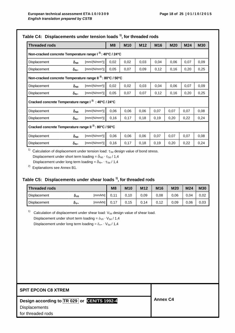
Table C4: Displacements under tension loads 1), for threaded rods
Threaded rods M8 M10 M12 M16 M20 M24 M30
Non-cracked concrete Temperature range I 2)
: 40°C / 24°C
Displacement N0 [mm/(N/mm²)] 0,02 0,02 0,03 0,04 0,06 0,07 0,09
Displacement N∞ [mm/(N/mm²)] 0,05 0,07 0,09 0,12 0,16 0,20 0,25
Non-cracked concrete Temperature range II 2)
: 80°C / 50°C
Displacement N0 [mm/(N/mm²)] 0,02 0,02 0,03 0,04 0,06 0,07 0,09
Displacement N∞ [mm/(N/mm²)] 0,05 0,07 0,07 0,12 0,16 0,20 0,25
Cracked concrete Temperature range I 2) : 40°C / 24°C
Displacement N0 [mm/(N/mm²)] 0,06 0,06 0,06 0,07 0,07 0,07 0,08
Displacement N∞ [mm/(N/mm²)] 0,16 0,17 0,18 0,19 0,20 0,22 0,24
Cracked concrete Temperature range II 2)
: 80°C / 50°C
Displacement N0 [mm/(N/mm²)] 0,06 0,06 0,06 0,07 0,07 0,07 0,08
Displacement N∞ [mm/(N/mm²)] 0,16 0,17 0,18 0,19 0,20 0,22 0,24
1) Calculation of displacement under tension load: Sd design value of bond stress.
Displacement under short term loading = N0 ∙ Sd / 1,4
Displacement under long term loading = N∞ ∙ Sd / 1,4 2)
Explanations see Annex B1.
Table C5: Displacements under shear loads 1), for threaded rods
Threaded rods M8 M10 M12 M16 M20 M24 M30
Displacement V0 [mm/kN] 0,11 0,10 0,09 0,08 0,06 0,04 0,02
Displacement V∞ [mm/kN] 0,17 0,15 0,14 0,12 0,09 0,06 0,03
1) Calculation of displacement under shear load: VSd design value of shear load.
Displacement under short term loading = V0 ∙ VSd / 1,4
Displacement under long term loading = v∞ ∙ VSd / 1,4
European technical assessment ETA-1 0 / 0 3 0 9
English translation prepared by CSTB
Page 19 of 25 | 0 1 / 1 0 / 2 0 1 5
SPIT EPCON C8 XTREM
Design according to TR 029 or CEN/TS 1992-4
Characteristic values for tension loads in non-cracked concrete for rebars
Annex C5
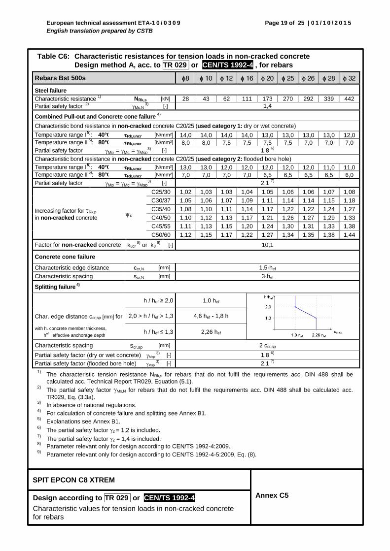
Table C6: Characteristic resistances for tension loads in non-cracked concrete
Design method A, acc. to TR 029 or CEN/TS 1992-4 , for rebars
Rebars Bst 500s 8 10 12 16 20 25 26 28 32
Steel failure
Characteristic resistance 1)
NRk,s [kN] 28 43 62 111 173 270 292 339 442
Partial safety factor 2)
Ms,N 3)
[-] 1,4
Combined Pull-out and Concrete cone failure 4)
Characteristic bond resistance in non-cracked concrete C20/25 (used category 1: dry or wet concrete)
Temperature range I 5)
: 40°C / 24°C Rk,uncr [N/mm²] 14,0 14,0 14,0 14,0 13,0 13,0 13,0 13,0 12,0
Temperature range II 5)
: 80°C / 50°C Rk,uncr [N/mm²] 8,0 8,0 7,5 7,5 7,5 7,5 7,0 7,0 7,0
Partial safety factor Mp =Mc =Msp3) [-] 1,8
6)
Characteristic bond resistance in non-cracked concrete C20/25 (used category 2: flooded bore hole)
Temperature range I 5)
: 40°C / 24°C Rk,uncr [N/mm²] 13,0 13,0 12,0 12,0 12,0 12,0 12,0 11,0 11,0
Temperature range II 5)
: 80°C / 50°C Rk,uncr [N/mm²] 7,0 7,0 7,0 7,0 6,5 6,5 6,5 6,5 6,0
Partial safety factor Mp =Mc =Msp3) [-] 2,1
7)
Increasing factor for Rk,p
in non-cracked concrete c
C25/30 1,02 1,03 1,03 1,04 1,05 1,06 1,06 1,07 1,08
C30/37 1,05 1,06 1,07 1,09 1,11 1,14 1,14 1,15 1,18
C35/40 1,08 1,10 1,11 1,14 1,17 1,22 1,22 1,24 1,27
C40/50 1,10 1,12 1,13 1,17 1,21 1,26 1,27 1,29 1,33
C45/55 1,11 1,13 1,15 1,20 1,24 1,30 1,31 1,33 1,38
C50/60 1,12 1,15 1,17 1,22 1,27 1,34 1,35 1,38 1,44
Factor for non-cracked concrete kucr 8)
or k8 9)
[-] 10,1
Concrete cone failure
Characteristic edge distance ccr,N [mm] 1,5·hef
Characteristic spacing scr,N [mm] 3·hef
Splitting failure 4)
Char. edge distance ccr,sp [mm] for
h / hef ≥ 2,0 1,0 hef
2,0 > h / hef > 1,3 4,6 hef - 1,8 h
with h. concrete member thickness,
hef effective anchorage depth
h / hef ≤ 1,3 2,26 hef
Characteristic spacing scr,sp [mm] 2 ccr,sp
Partial safety factor (dry or wet concrete) Msp 3)
[-] 1,8 6)
Partial safety factor (flooded bore hole) Msp 3)
[-] 2,1 7)
1) The characteristic tension resistance NRk,s for rebars that do not fulfil the requirements acc. DIN 488 shall be
calculated acc. Technical Report TR029, Equation (5.1). 2)
The partial safety factor Ms,N for rebars that do not fulfil the requirements acc. DIN 488 shall be calculated acc.
TR029, Eq. (3.3a). 3)
In absence of national regulations. 4)
For calculation of concrete failure and splitting see Annex B1.
5) Explanations see Annex B1.
6) The partial safety factor 2
= 1,2 is included.
7) The partial safety factor 2 = 1,4 is included.
8) Parameter relevant only for design according to CEN/TS 1992-4:2009.
9) Parameter relevant only for design according to CEN/TS 1992-4-5:2009, Eq. (8).
European technical assessment ETA-1 0 / 0 3 0 9
English translation prepared by CSTB
Page 20 of 25 | 0 1 / 1 0 / 2 0 1 5
SPIT EPCON C8 XTREM
Design according to TR 029 or CEN/TS 1992-4
Characteristic values for tension loads in cracked concrete for rebars
Annex C6
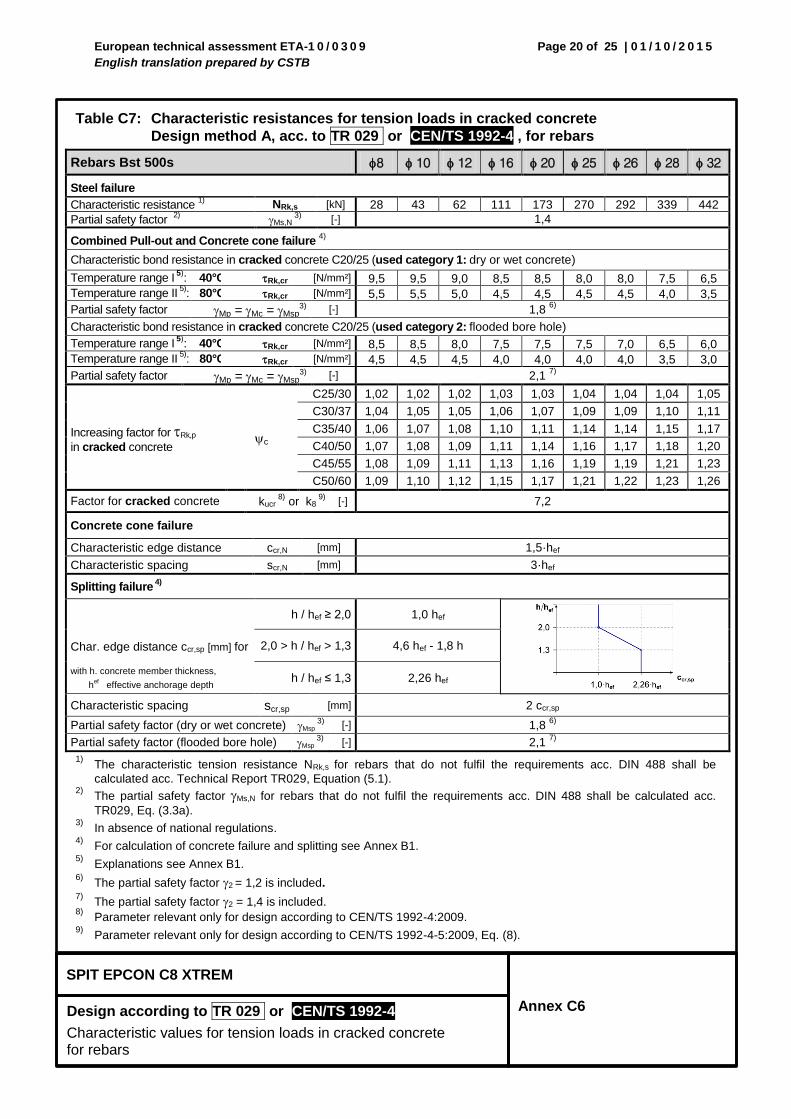
Table C7: Characteristic resistances for tension loads in cracked concrete
Design method A, acc. to TR 029 or CEN/TS 1992-4 , for rebars
Rebars Bst 500s 8 10 12 16 20 25 26 28 32
Steel failure
Characteristic resistance 1)
NRk,s [kN] 28 43 62 111 173 270 292 339 442
Partial safety factor 2)
Ms,N 3)
[-] 1,4
Combined Pull-out and Concrete cone failure 4)
Characteristic bond resistance in cracked concrete C20/25 (used category 1: dry or wet concrete)
Temperature range I 5)
: 40°C / 24°C Rk,cr [N/mm²] 9,5 9,5 9,0 8,5 8,5 8,0 8,0 7,5 6,5
Temperature range II 5)
: 80°C / 50°C Rk,cr [N/mm²] 5,5 5,5 5,0 4,5 4,5 4,5 4,5 4,0 3,5
Partial safety factor Mp =Mc =Msp3) [-] 1,8
6)
Characteristic bond resistance in cracked concrete C20/25 (used category 2: flooded bore hole)
Temperature range I 5)
: 40°C / 24°C Rk,cr [N/mm²] 8,5 8,5 8,0 7,5 7,5 7,5 7,0 6,5 6,0
Temperature range II 5)
: 80°C / 50°C Rk,cr [N/mm²] 4,5 4,5 4,5 4,0 4,0 4,0 4,0 3,5 3,0
Partial safety factor Mp =Mc =Msp3) [-] 2,1
7)
Increasing factor for Rk,p
in cracked concrete c
C25/30 1,02 1,02 1,02 1,03 1,03 1,04 1,04 1,04 1,05
C30/37 1,04 1,05 1,05 1,06 1,07 1,09 1,09 1,10 1,11
C35/40 1,06 1,07 1,08 1,10 1,11 1,14 1,14 1,15 1,17
C40/50 1,07 1,08 1,09 1,11 1,14 1,16 1,17 1,18 1,20
C45/55 1,08 1,09 1,11 1,13 1,16 1,19 1,19 1,21 1,23
C50/60 1,09 1,10 1,12 1,15 1,17 1,21 1,22 1,23 1,26
Factor for cracked concrete kucr 8)
or k8 9)
[-] 7,2
Concrete cone failure
Characteristic edge distance ccr,N [mm] 1,5·hef
Characteristic spacing scr,N [mm] 3·hef
Splitting failure 4)
Char. edge distance ccr,sp [mm] for
h / hef ≥ 2,0 1,0 hef
2,0 > h / hef > 1,3 4,6 hef - 1,8 h
with h. concrete member thickness,
hef effective anchorage depth
h / hef ≤ 1,3 2,26 hef
Characteristic spacing scr,sp [mm] 2 ccr,sp
Partial safety factor (dry or wet concrete) Msp 3)
[-] 1,8 6)
Partial safety factor (flooded bore hole) Msp 3)
[-] 2,1 7)
1) The characteristic tension resistance NRk,s for rebars that do not fulfil the requirements acc. DIN 488 shall be
calculated acc. Technical Report TR029, Equation (5.1). 2)
The partial safety factor Ms,N for rebars that do not fulfil the requirements acc. DIN 488 shall be calculated acc.
TR029, Eq. (3.3a). 3)
In absence of national regulations. 4)
For calculation of concrete failure and splitting see Annex B1.
5) Explanations see Annex B1.
6) The partial safety factor 2
= 1,2 is included.
7) The partial safety factor 2 = 1,4 is included.
8) Parameter relevant only for design according to CEN/TS 1992-4:2009.
9) Parameter relevant only for design according to CEN/TS 1992-4-5:2009, Eq. (8).
European technical assessment ETA-1 0 / 0 3 0 9
English translation prepared by CSTB
Page 21 of 25 | 0 1 / 1 0 / 2 0 1 5
SPIT EPCON C8 XTREM
Design according to TR 029 or CEN/TS 1992-4
Characteristic values for shear loads for rebars
Annex C7
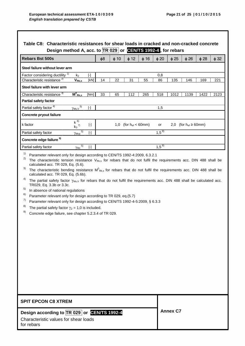
Table C8: Characteristic resistances for shear loads in cracked and non-cracked concrete
Design method A, acc. to TR 029 or CEN/TS 1992-4 , for rebars
Rebars Bst 500s 8 10 12 16 20 25 26 28 32
Steel failure without lever arm
Factor considering ductility 1)
k2 [-] 0,8
Characteristic resistance 2)
VRk,s [kN] 14 22 31 55 86 135 146 169 221
Steel failure with lever arm
Characteristic resistance 3)
M0
Rk,s [Nm] 33 65 112 265 518 1012 1139 1422 2123
Partial safety factor
Partial safety factor 4)
Ms,V 5)
[-] 1,5
Concrete pryout failure
k factor k
6)
k3 7)
[-] 1,0 (for hef < 60mm) or 2,0 (for hef ≥ 60mm)
Partial safety factor Mcp 5)
[-] 1,5 8)
Concrete edge failure 9)
Partial safety factor Mc 5)
[-] 1,5 8)
1) Parameter relevant only for design according to CEN/TS 1992-4:2009, 6.3.2.1
2) The characteristic tension resistance VRk,s for rebars that do not fulfil the requirements acc. DIN 488 shall be
calculated acc. TR 029, Eq. (5.6). 3)
The characteristic bending resistance M0
Rk,s for rebars that do not fulfil the requirements acc. DIN 488 shall be
calculated acc. TR 029, Eq. (5.6b). 4)
The partial safety factor Ms,V for rebars that do not fulfil the requirements acc. DIN 488 shall be calculated acc.
TR029, Eq. 3.3b or 3.3c. 5) In absence of national regulations
6) Parameter relevant only for design according to TR 029, eq.(5.7)
7) Parameter relevant only for design according to CEN/TS 1992-4-5:2009, § 6.3.3
8) The partial safety factor 2 = 1,0 is included.
9) Concrete edge failure, see chapter 5.2.3.4 of TR 029.
European technical assessment ETA-1 0 / 0 3 0 9
English translation prepared by CSTB
Page 22 of 25 | 0 1 / 1 0 / 2 0 1 5
SPIT EPCON C8 XTREM
Design according to TR 029 or CEN/TS 1992-4
Displacements for rebars
Annex C8
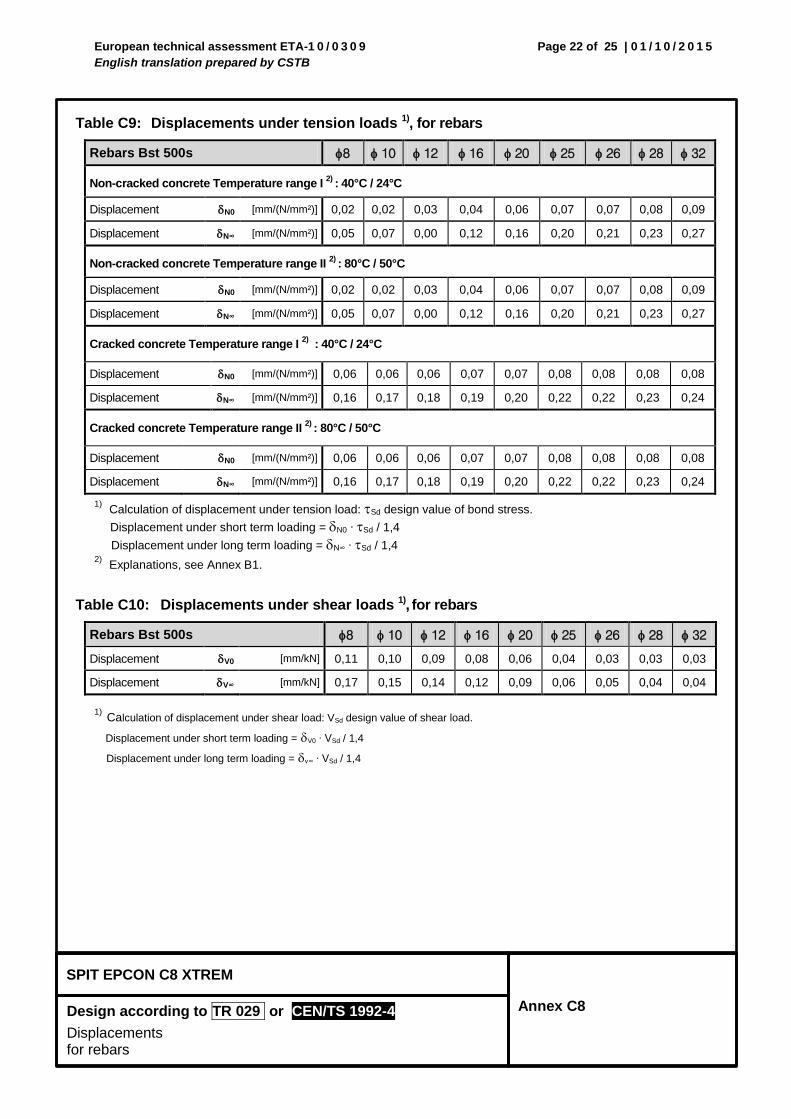
Table C9: Displacements under tension loads 1), for rebars
Rebars Bst 500s 8 10 12 16 20 25 26 28 32
Non-cracked concrete Temperature range I 2)
: 40°C / 24°C
Displacement N0 [mm/(N/mm²)] 0,02 0,02 0,03 0,04 0,06 0,07 0,07 0,08 0,09
Displacement N∞ [mm/(N/mm²)] 0,05 0,07 0,00 0,12 0,16 0,20 0,21 0,23 0,27
Non-cracked concrete Temperature range II 2)
: 80°C / 50°C
Displacement N0 [mm/(N/mm²)] 0,02 0,02 0,03 0,04 0,06 0,07 0,07 0,08 0,09
Displacement N∞ [mm/(N/mm²)] 0,05 0,07 0,00 0,12 0,16 0,20 0,21 0,23 0,27
Cracked concrete Temperature range I 2) : 40°C / 24°C
Displacement N0 [mm/(N/mm²)] 0,06 0,06 0,06 0,07 0,07 0,08 0,08 0,08 0,08
Displacement N∞ [mm/(N/mm²)] 0,16 0,17 0,18 0,19 0,20 0,22 0,22 0,23 0,24
Cracked concrete Temperature range II 2)
: 80°C / 50°C
Displacement N0 [mm/(N/mm²)] 0,06 0,06 0,06 0,07 0,07 0,08 0,08 0,08 0,08
Displacement N∞ [mm/(N/mm²)] 0,16 0,17 0,18 0,19 0,20 0,22 0,22 0,23 0,24
1) Calculation of displacement under tension load: Sd design value of bond stress.
Displacement under short term loading = N0 ∙ Sd / 1,4
Displacement under long term loading = N∞ ∙ Sd / 1,4 2)
Explanations, see Annex B1.
Table C10: Displacements under shear loads 1), for rebars
Rebars Bst 500s 8 10 12 16 20 25 26 28 32
Displacement V0 [mm/kN] 0,11 0,10 0,09 0,08 0,06 0,04 0,03 0,03 0,03
Displacement V∞ [mm/kN] 0,17 0,15 0,14 0,12 0,09 0,06 0,05 0,04 0,04
1) Calculation of displacement under shear load: VSd design value of shear load.
Displacement under short term loading = V0 ∙ VSd / 1,4
Displacement under long term loading = v∞ ∙ VSd / 1,4
European technical assessment ETA-1 0 / 0 3 0 9
English translation prepared by CSTB
Page 23 of 25 | 0 1 / 1 0 / 2 0 1 5
SPIT EPCON C8 XTREM
Seismic performance categories
Annex C9
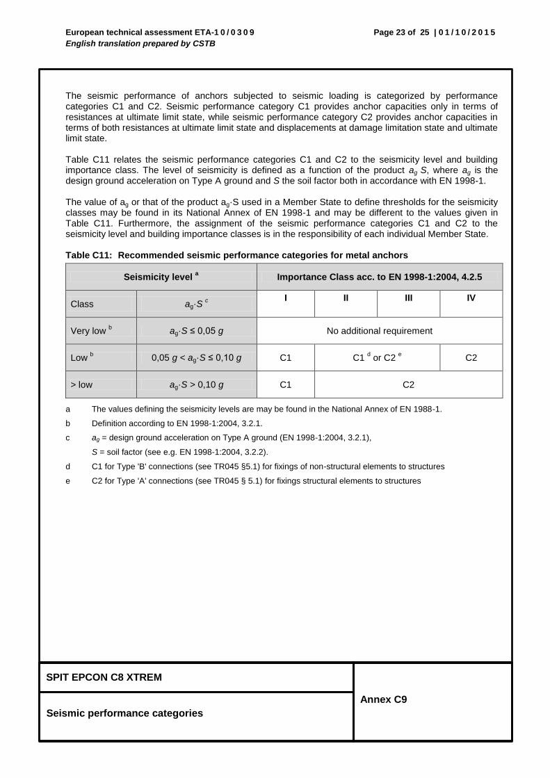
The seismic performance of anchors subjected to seismic loading is categorized by performance categories C1 and C2. Seismic performance category C1 provides anchor capacities only in terms of resistances at ultimate limit state, while seismic performance category C2 provides anchor capacities in terms of both resistances at ultimate limit state and displacements at damage limitation state and ultimate limit state. Table C11 relates the seismic performance categories C1 and C2 to the seismicity level and building importance class. The level of seismicity is defined as a function of the product ag·S, where ag is the design ground acceleration on Type A ground and S the soil factor both in accordance with EN 1998-1. The value of ag or that of the product ag·S used in a Member State to define thresholds for the seismicity classes may be found in its National Annex of EN 1998-1 and may be different to the values given in Table C11. Furthermore, the assignment of the seismic performance categories C1 and C2 to the seismicity level and building importance classes is in the responsibility of each individual Member State. Table C11: Recommended seismic performance categories for metal anchors
Seismicity level a Importance Class acc. to EN 1998-1:2004, 4.2.5
Class ag·S c
I II III IV
Very low b ag·S ≤ 0,05 g No additional requirement
Low b 0,05 g < ag·S ≤ 0,10 g C1 C1
d or C2
e C2
> low ag·S > 0,10 g C1 C2
a The values defining the seismicity levels are may be found in the National Annex of EN 1988-1.
b Definition according to EN 1998-1:2004, 3.2.1.
c ag = design ground acceleration on Type A ground (EN 1998-1:2004, 3.2.1),
S = soil factor (see e.g. EN 1998-1:2004, 3.2.2).
d C1 for Type 'B' connections (see TR045 §5.1) for fixings of non-structural elements to structures
e C2 for Type 'A' connections (see TR045 § 5.1) for fixings structural elements to structures
European technical assessment ETA-1 0 / 0 3 0 9
English translation prepared by CSTB
Page 24 of 25 | 0 1 / 1 0 / 2 0 1 5
SPIT EPCON C8 XTREM
Reduction factors and characteristic seismic resistances
Annex C10
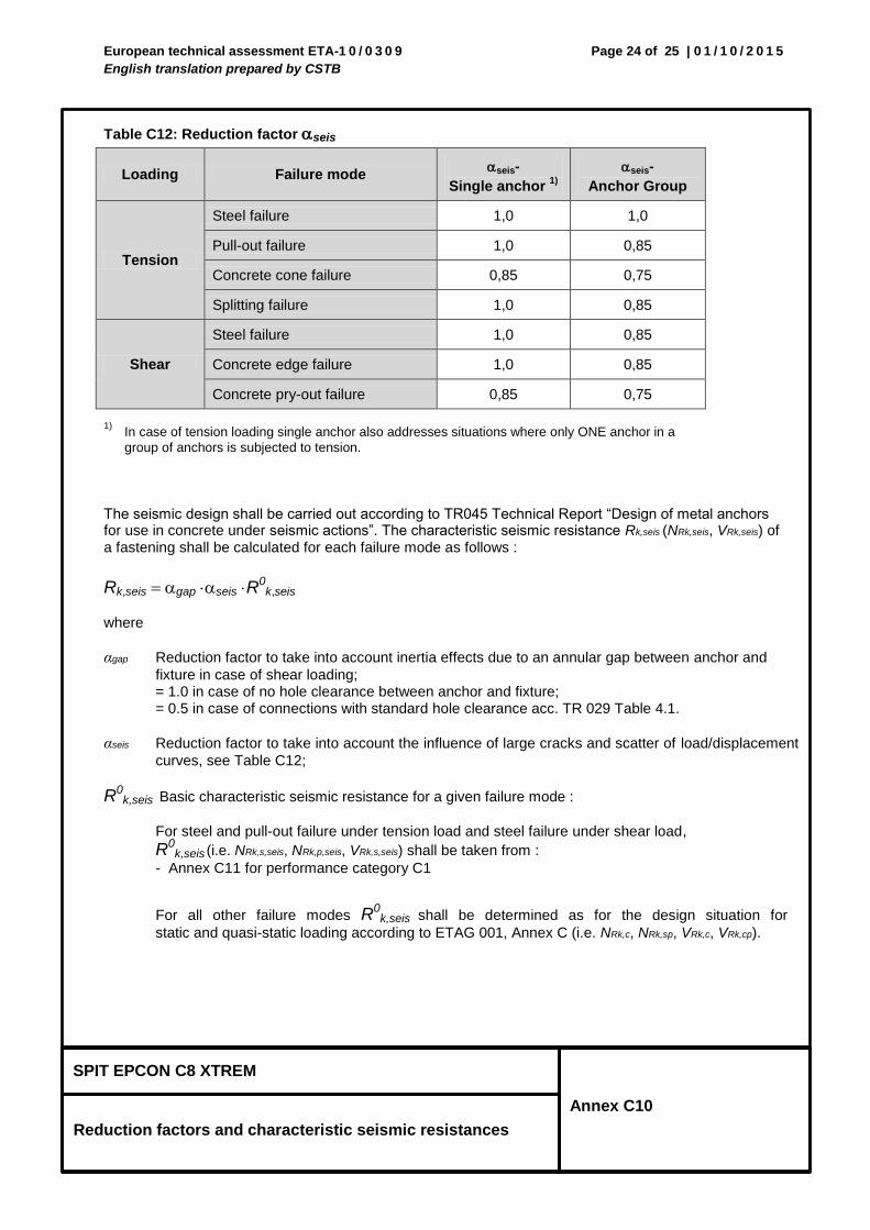
Table C12: Reduction factor seis
Loading Failure mode seis-
Single anchor 1)
seis-
Anchor Group
Tension
Steel failure 1,0 1,0
Pull-out failure 1,0 0,85
Concrete cone failure 0,85 0,75
Splitting failure 1,0 0,85
Shear
Steel failure 1,0 0,85
Concrete edge failure 1,0 0,85
Concrete pry-out failure 0,85 0,75
1) In case of tension loading single anchor also addresses situations where only ONE anchor in a
group of anchors is subjected to tension.
The seismic design shall be carried out according to TR045 Technical Report “Design of metal anchors for use in concrete under seismic actions”. The characteristic seismic resistance Rk,seis (NRk,seis, VRk,seis) of a fastening shall be calculated for each failure mode as follows :
Rk,seis gap seis R0k,seis
where
αgap Reduction factor to take into account inertia effects due to an annular gap between anchor and
fixture in case of shear loading; = 1.0 in case of no hole clearance between anchor and fixture; = 0.5 in case of connections with standard hole clearance acc. TR 029 Table 4.1.
αseis Reduction factor to take into account the influence of large cracks and scatter of load/displacement
curves, see Table C12;
R0k,seis Basic characteristic seismic resistance for a given failure mode :
For steel and pull-out failure under tension load and steel failure under shear load,
R0k,seis (i.e. NRk,s,seis, NRk,p,seis, VRk,s,seis) shall be taken from :
- Annex C11 for performance category C1
For all other failure modes R0k,seis shall be determined as for the design situation for
static and quasi-static loading according to ETAG 001, Annex C (i.e. NRk,c, NRk,sp, VRk,c, VRk,cp).
European technical assessment ETA-1 0 / 0 3 0 9
English translation prepared by CSTB
Page 25 of 25 | 0 1 / 1 0 / 2 0 1 5
SPIT EPCON C8 XTREM
Design according to TR045
Characteristic resistance under seismic action (C1)
for threaded rods
Annex C11
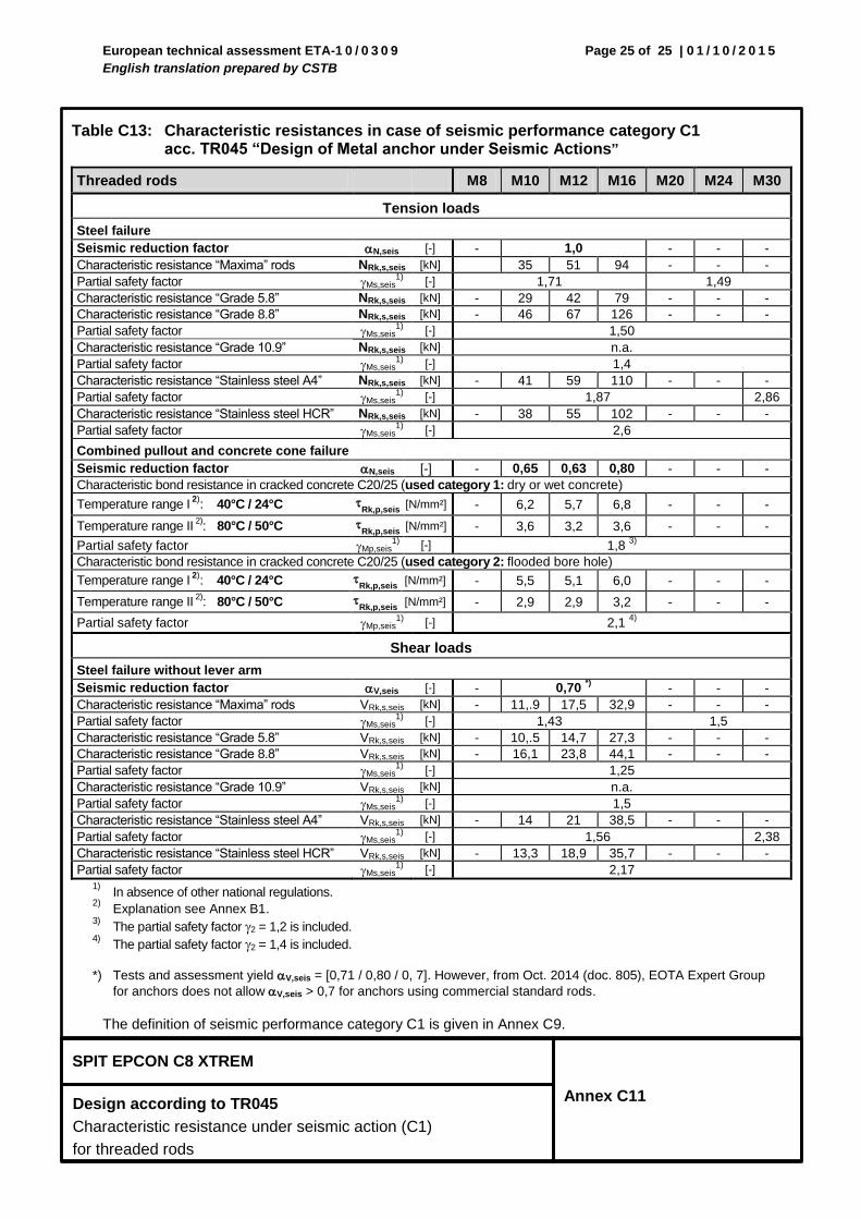
Table C13: Characteristic resistances in case of seismic performance category C1
acc. TR045 “Design of Metal anchor under Seismic Actions”
Threaded rods M8 M10 M12 M16 M20 M24 M30
Tension loads
Steel failure
Seismic reduction factor N,seis [-] - 1,0 - - -
Characteristic resistance “Maxima” rods NRk,s,seis [kN] 35 51 94 - - -
Partial safety factor Ms,seis1)
[-] 1,71 1,49
Characteristic resistance “Grade 5.8” NRk,s,seis [kN] - 29 42 79 - - -
Characteristic resistance “Grade 8.8” NRk,s,seis [kN] - 46 67 126 - - -
Partial safety factor Ms,seis1)
[-] 1,50
Characteristic resistance “Grade 10.9” NRk,s,seis [kN] n.a.
Partial safety factor Ms,seis1)
[-] 1,4
Characteristic resistance “Stainless steel A4” NRk,s,seis [kN] - 41 59 110 - - -
Partial safety factor Ms,seis1)
[-] 1,87 2,86
Characteristic resistance “Stainless steel HCR” NRk,s,seis [kN] - 38 55 102 - - -
Partial safety factor Ms,seis1)
[-] 2,6
Combined pullout and concrete cone failure
Seismic reduction factor N,seis [-] - 0,65 0,63 0,80 - - -
Characteristic bond resistance in cracked concrete C20/25 (used category 1: dry or wet concrete)
Temperature range I 2)
: 40°C / 24°C Rk,p,seis
[N/mm²] - 6,2 5,7 6,8 - - -
Temperature range II 2)
: 80°C / 50°C Rk,p,seis
[N/mm²] - 3,6 3,2 3,6 - - -
Partial safety factor Mp,seis1) [-] 1,8
3)
Characteristic bond resistance in cracked concrete C20/25 (used category 2: flooded bore hole)
Temperature range I 2)
: 40°C / 24°C Rk,p,seis
[N/mm²] - 5,5 5,1 6,0 - - -
Temperature range II 2)
: 80°C / 50°C Rk,p,seis
[N/mm²] - 2,9 2,9 3,2 - - -
Partial safety factor Mp,seis1) [-] 2,1
4)
Shear loads
Steel failure without lever arm
Seismic reduction factor V,seis [-] - 0,70 *)
- - -
Characteristic resistance “Maxima” rods VRk,s,seis [kN] - 11,.9 17,5 32,9 - - -
Partial safety factor Ms,seis1)
[-] 1,43 1,5
Characteristic resistance “Grade 5.8” VRk,s,seis [kN] - 10,.5 14,7 27,3 - - -
Characteristic resistance “Grade 8.8” VRk,s,seis [kN] - 16,1 23,8 44,1 - - -
Partial safety factor Ms,seis1)
[-] 1,25
Characteristic resistance “Grade 10.9” VRk,s,seis [kN] n.a.
Partial safety factor Ms,seis1)
[-] 1,5
Characteristic resistance “Stainless steel A4” VRk,s,seis [kN] - 14 21 38,5 - - -
Partial safety factor Ms,seis1)
[-] 1,56 2,38
Characteristic resistance “Stainless steel HCR” VRk,s,seis [kN] - 13,3 18,9 35,7 - - -
Partial safety factor Ms,seis1)
[-] 2,17
1) In absence of other national regulations.
2) Explanation see Annex B1.
3) The partial safety factor 2 = 1,2 is included.
4) The partial safety factor 2 = 1,4 is included.
*) Tests and assessment yield V,seis = [0,71 / 0,80 / 0, 7]. However, from Oct. 2014 (doc. 805), EOTA Expert Group
for anchors does not allow V,seis > 0,7 for anchors using commercial standard rods.
The definition of seismic performance category C1 is given in Annex C9.
Top Related