


γλώσσες
Σελίδες
Νομικός

8/28/2003 Electromechanical Dynamics 1
Chapter 2: Fundamentals of Magnetism
8/28/2003 Electromechanical Dynamics 2
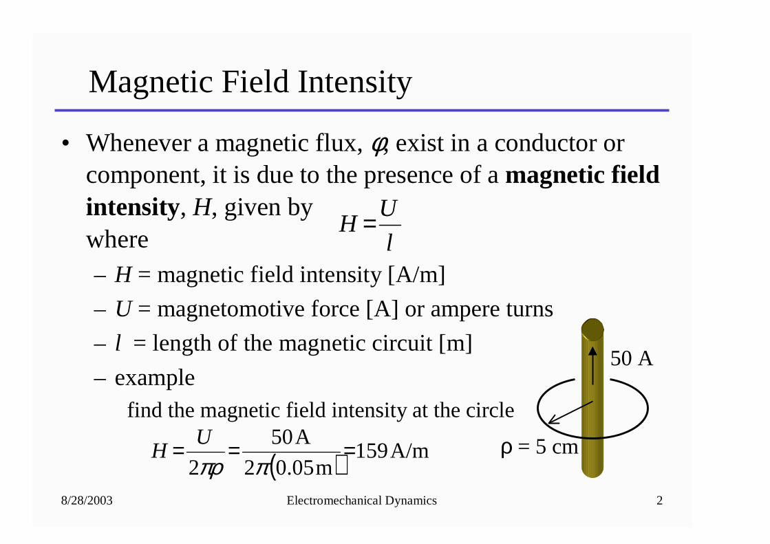
Magnetic Field Intensity
• Whenever a magnetic flux, φ, exist in a conductor or component, it is due to the presence of a magnetic field intensity, H, given bywhere– H = magnetic field intensity [A/m]
– U = magnetomotive force [A] or ampere turns
– l = length of the magnetic circuit [m]
– examplefind the magnetic field intensity at the circle
l
UH =
ρ = 5 cm( ) A/m159
m05.02
A50
2===
ππρU
H
50 A
8/28/2003 Electromechanical Dynamics 3
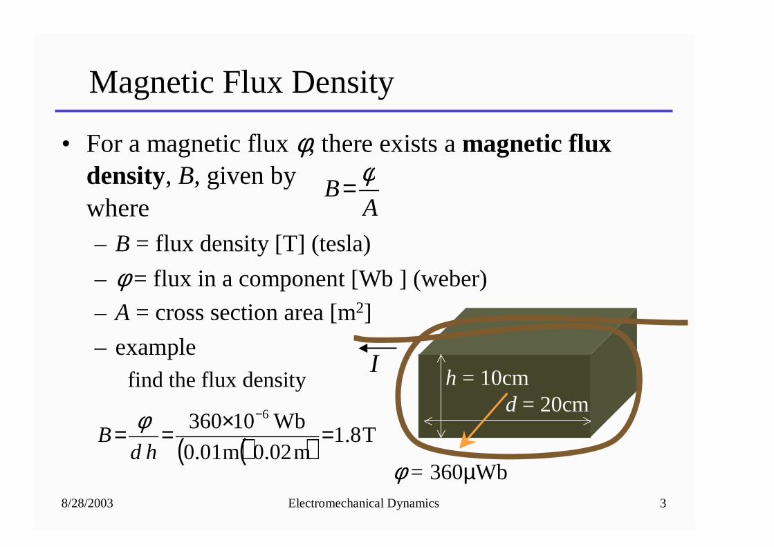
Magnetic Flux Density
• For a magnetic flux φ, there exists a magnetic flux density, B, given bywhere– B = flux density [T] (tesla)
– φ = flux in a component [Wb ] (weber)
– A = cross section area [m2]
– examplefind the flux density
AB
φ=
( )( ) T8.1m02.0m01.0
Wb10360 6
=×==−
hdB
φd = 20cm
h = 10cm
φ = 360µWb
I
8/28/2003 Electromechanical Dynamics 4
Relationship between B-H in Free Space
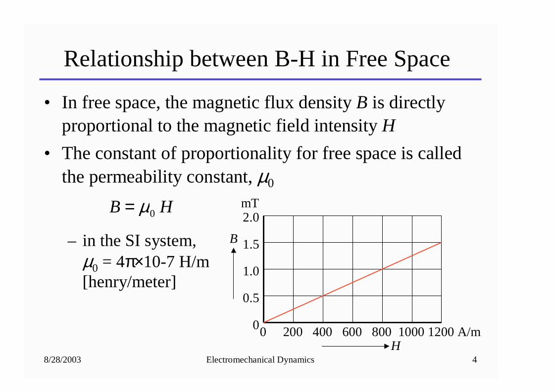
• In free space, the magnetic flux density B is directly proportional to the magnetic field intensity H
• The constant of proportionality for free space is called the permeability constant, µ0
– in the SI system, µ0 = 4π×10-7 H/m[henry/meter]
HB 0µ=
0 200 400 600 800 1000 1200 A/m
mT2.0
1.5
1.0
0.5
0
H
B
8/28/2003 Electromechanical Dynamics 5
B-H Characteristic of Magnetic Material
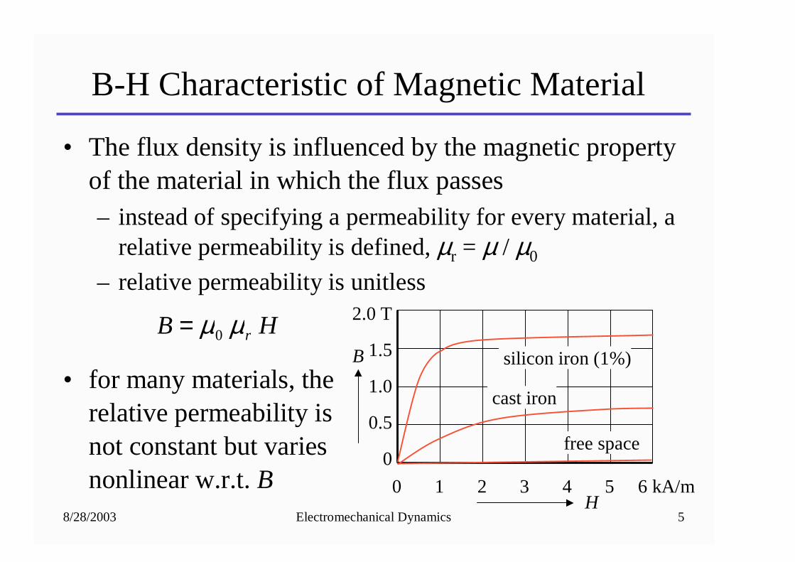
• The flux density is influenced by the magnetic property of the material in which the flux passes– instead of specifying a permeability for every material, a
relative permeability is defined, µr = µ / µ0
– relative permeability is unitless
• for many materials, the relative permeability isnot constant but variesnonlinear w.r.t. B
HB rµµ0= 2.0 T
1.5
1.0
0.5
0
H
B
0 1 2 3 4 5 6 kA/m
cast iron
silicon iron (1%)
free space
8/28/2003 Electromechanical Dynamics 6
Determining Relative Permeability
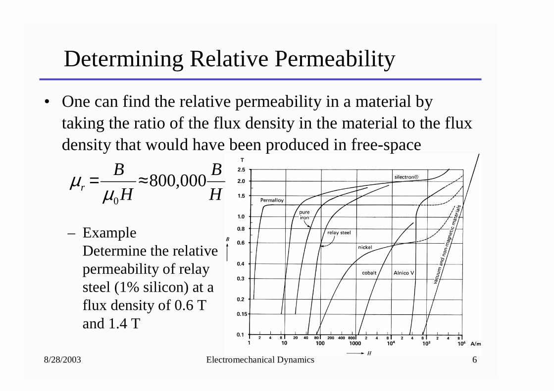
• One can find the relative permeability in a material by taking the ratio of the flux density in the material to the fluxdensity that would have been produced in free-space
– ExampleDetermine the relativepermeability of relaysteel (1% silicon) at aflux density of 0.6 Tand 1.4 T
H
B
H
Br 000,800
0
≈=µ
µ
8/28/2003 Electromechanical Dynamics 7
Faraday’s Law
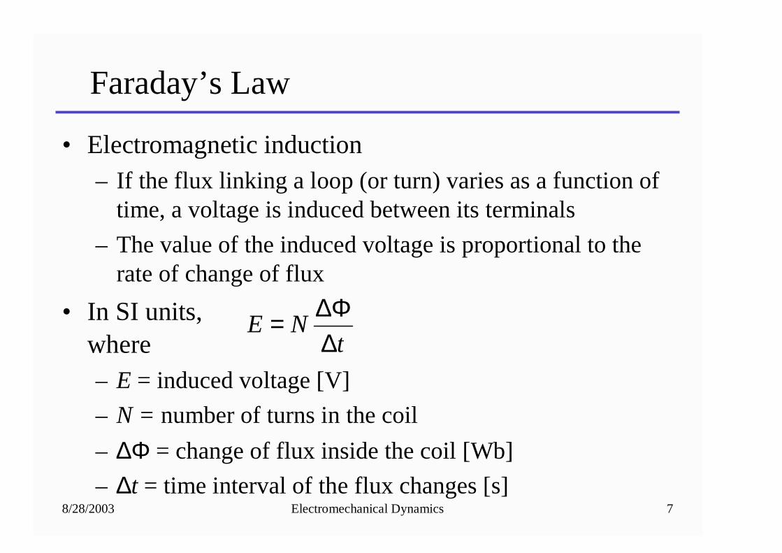
• Electromagnetic induction– If the flux linking a loop (or turn) varies as a function of
time, a voltage is induced between its terminals
– The value of the induced voltage is proportional to the rate of change of flux
• In SI units,where– E = induced voltage [V]
– N = number of turns in the coil
– ∆Φ = change of flux inside the coil [Wb]
– ∆t = time interval of the flux changes [s]
tNE
∆∆Φ=
8/28/2003 Electromechanical Dynamics 8
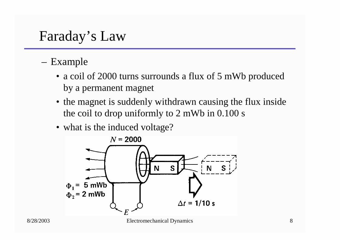
Faraday’s Law
– Example• a coil of 2000 turns surrounds a flux of 5 mWb produced
by a permanent magnet
• the magnet is suddenly withdrawn causing the flux inside the coil to drop uniformly to 2 mWb in 0.100 s
• what is the induced voltage?
8/28/2003 Electromechanical Dynamics 9
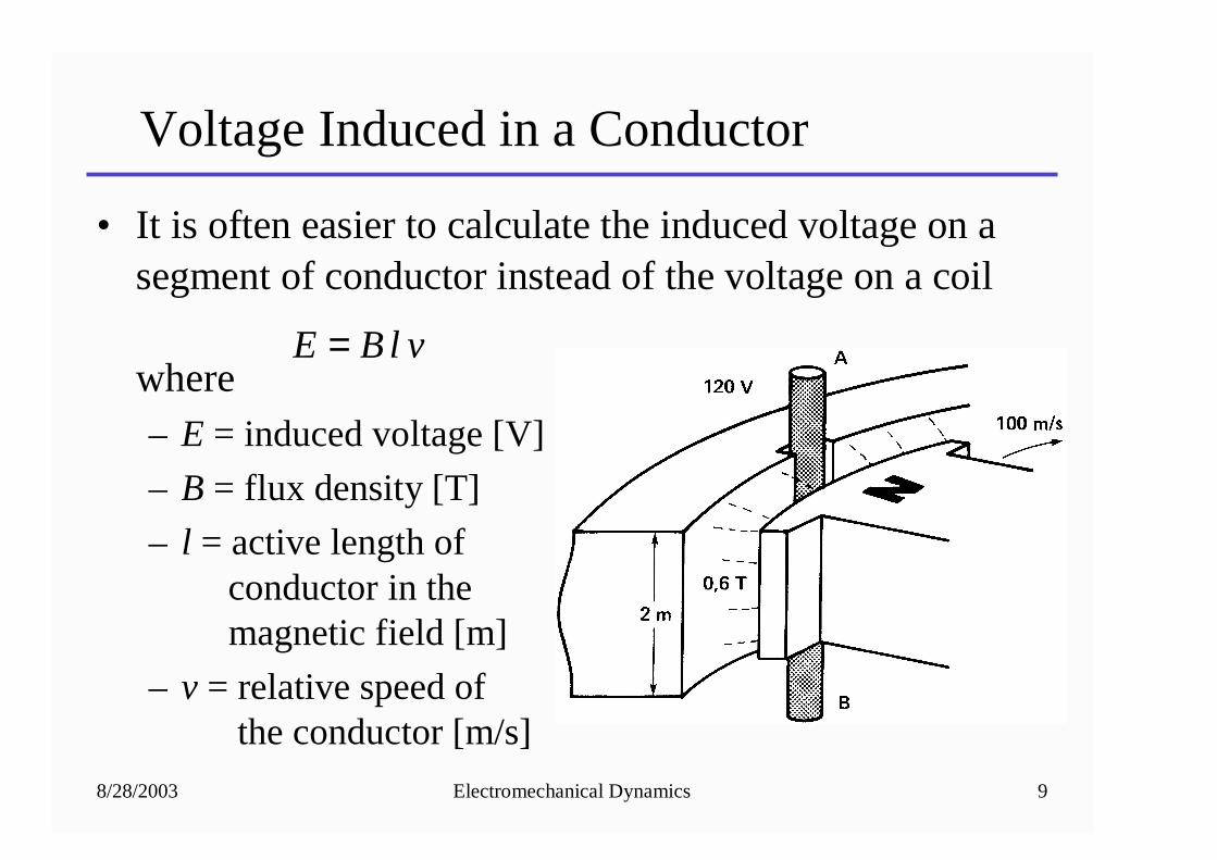
Voltage Induced in a Conductor
• It is often easier to calculate the induced voltage on a segment of conductor instead of the voltage on a coil
where– E = induced voltage [V]
– B = flux density [T]
– l = active length of conductor in themagnetic field [m]
– v = relative speed of the conductor [m/s]
vlBE =
8/28/2003 Electromechanical Dynamics 10
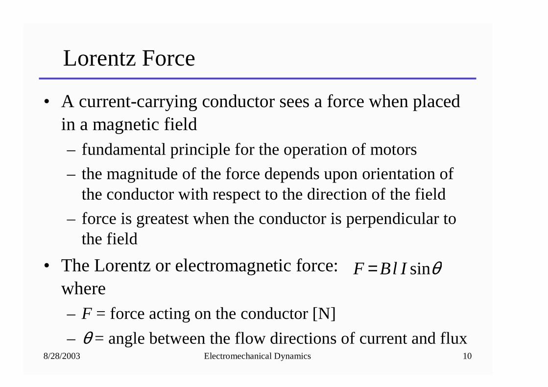
Lorentz Force
• A current-carrying conductor sees a force when placed in a magnetic field– fundamental principle for the operation of motors
– the magnitude of the force depends upon orientation of the conductor with respect to the direction of the field
– force is greatest when the conductor is perpendicular to the field
• The Lorentz or electromagnetic force:where– F = force acting on the conductor [N]
– θ = angle between the flow directions of current and flux
θsinIlBF =
8/28/2003 Electromechanical Dynamics 11
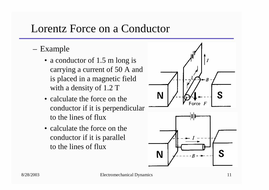
Lorentz Force on a Conductor
– Example• a conductor of 1.5 m long is
carrying a current of 50 A andis placed in a magnetic fieldwith a density of 1.2 T
• calculate the force on the conductor if it is perpendicularto the lines of flux
• calculate the force on theconductor if it is parallelto the lines of flux
8/28/2003 Electromechanical Dynamics 12
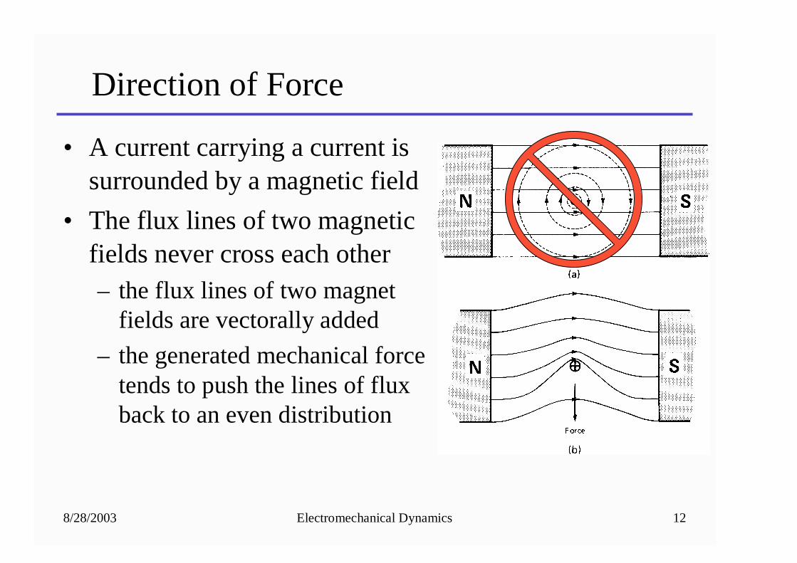
Direction of Force
• A current carrying a current issurrounded by a magnetic field
• The flux lines of two magneticfields never cross each other– the flux lines of two magnet
fields are vectorally added
– the generated mechanical forcetends to push the lines of fluxback to an even distribution
8/28/2003 Electromechanical Dynamics 13
Direction of Force
• Right hand rule– Fingers point in the direction of current flow
(positive to negative)
– Bend fingers into the direction of the magnetic field (north to south)
– Thumb points in the direction of force
8/28/2003 Electromechanical Dynamics 14
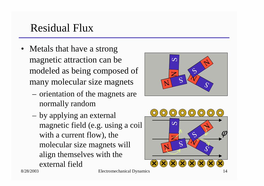
Residual Flux
• Metals that have a strong magnetic attraction can be modeled as being composed of many molecular size magnets– orientation of the magnets are
normally random
– by applying an external magnetic field (e.g. using a coil with a current flow), the molecular size magnets will align themselves with the external field
NS
NS
NS
N S
NS
NS
NS
N S
φ
8/28/2003 Electromechanical Dynamics 15
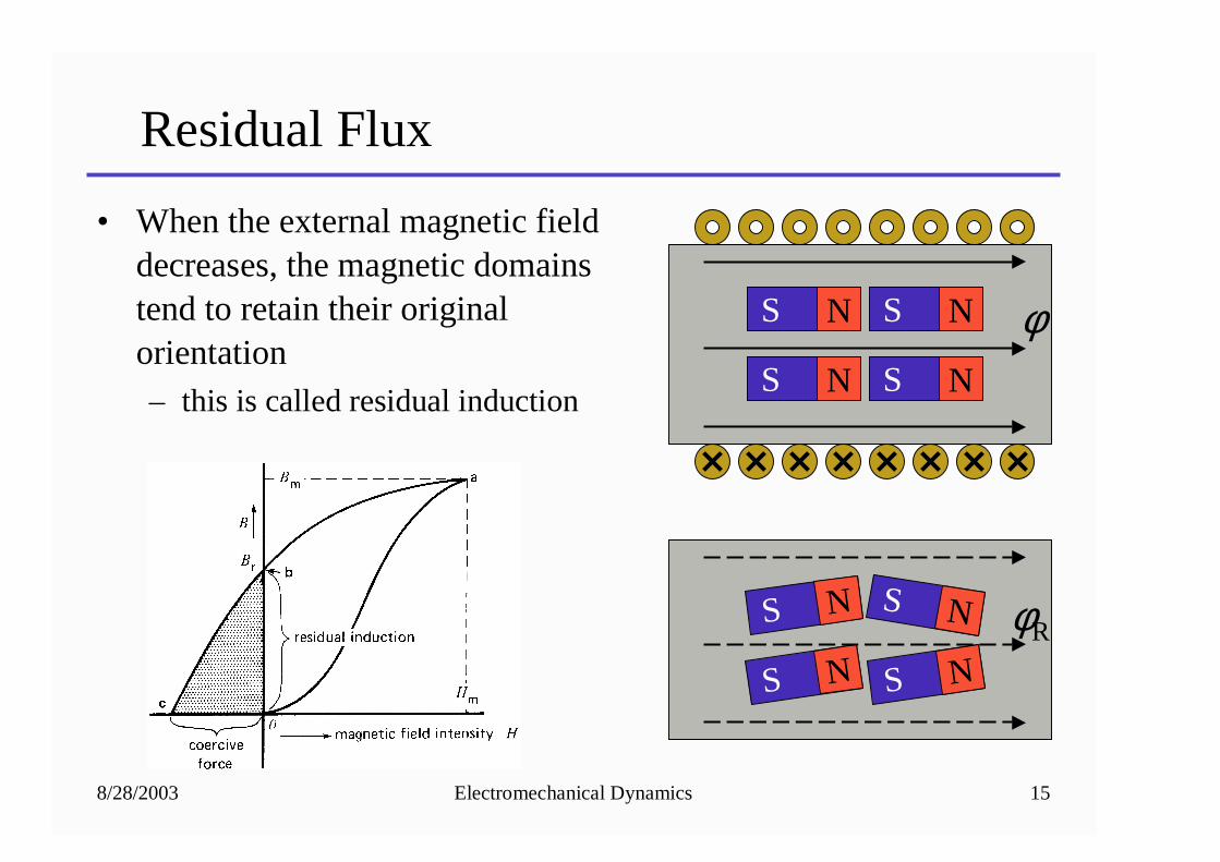
Residual Flux
• When the external magnetic fielddecreases, the magnetic domainstend to retain their original orientation– this is called residual induction
NS
NS
NS
NS
φR
NS
NS
NS
NS
φ
8/28/2003 Electromechanical Dynamics 16
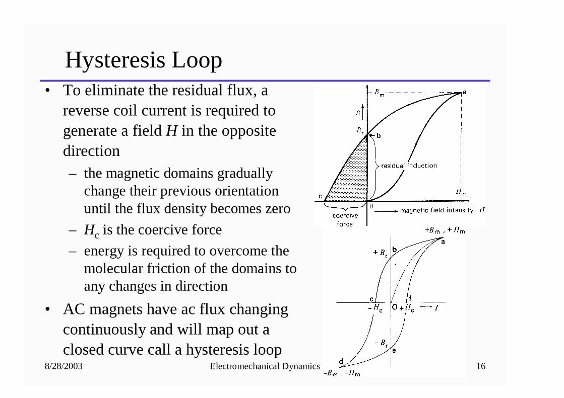
Hysteresis Loop• To eliminate the residual flux, a
reverse coil current is required to generate a field H in the opposite direction– the magnetic domains gradually
change their previous orientation until the flux density becomes zero
– Hc is the coercive force
– energy is required to overcome the molecular friction of the domains to any changes in direction
• AC magnets have ac flux changing continuously and will map out a closed curve call a hysteresis loop
8/28/2003 Electromechanical Dynamics 17
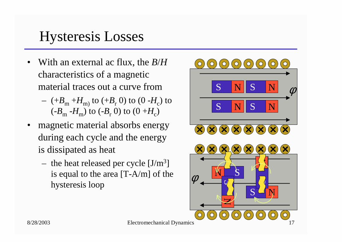
Hysteresis Losses
• With an external ac flux, the B/Hcharacteristics of a magnetic material traces out a curve from– (+Bm +Hm) to (+Br 0) to (0 -Hc) to
(-Bm -Hm) to (-Br 0) to (0 +Hc)
• magnetic material absorbs energy during each cycle and the energy is dissipated as heat– the heat released per cycle [J/m3]
is equal to the area [T-A/m] of the hysteresis loop
NS
NS
NS
NS
N S
NS
NS
NS
φ
φ
8/28/2003 Electromechanical Dynamics 18
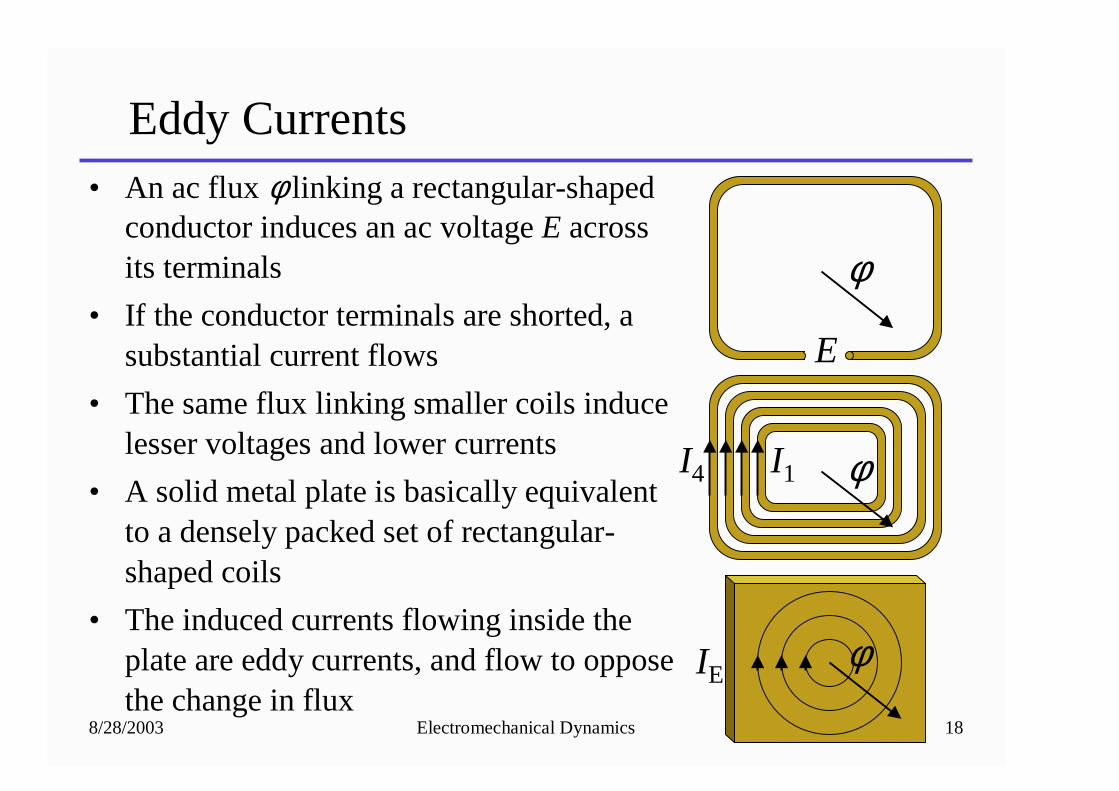
Eddy Currents• An ac flux φ linking a rectangular-shaped
conductor induces an ac voltage E across its terminals
• If the conductor terminals are shorted, a substantial current flows
• The same flux linking smaller coils induce lesser voltages and lower currents
• A solid metal plate is basically equivalent to a densely packed set of rectangular-shaped coils
• The induced currents flowing inside the plate are eddy currents, and flow to oppose the change in flux
φ
φ
φ
E
I1I4
IE
8/28/2003 Electromechanical Dynamics 19
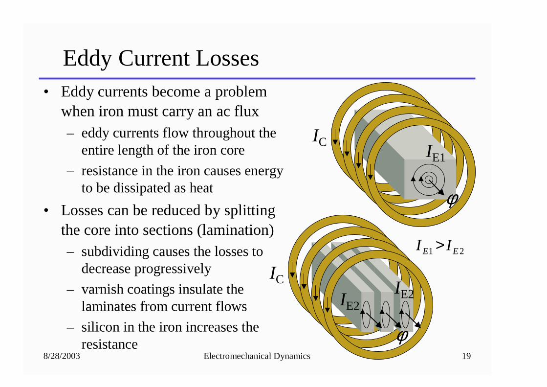
Eddy Current Losses• Eddy currents become a problem
when iron must carry an ac flux– eddy currents flow throughout the
entire length of the iron core
– resistance in the iron causes energy to be dissipated as heat
• Losses can be reduced by splitting the core into sections (lamination)– subdividing causes the losses to
decrease progressively
– varnish coatings insulate the laminates from current flows
– silicon in the iron increases the resistance
φ
φ
ICIE1
ICIE2
21 EE II >
IE2
8/28/2003 Electromechanical Dynamics 20
Homework
• Problems:– 1-90, 1-91, 1-97
– 2-4, 2-5, 2-7, 2-8, and 2-9
Top Related