Why Time Domain - CST Computer Simulation Technology · •May-06 Contents Power Plane Analysis TDR...
19
www.cst.com • May-06 Why Time Domain ? JAY
Transcript of Why Time Domain - CST Computer Simulation Technology · •May-06 Contents Power Plane Analysis TDR...
www.cst.com • May-06
Why Time Domain ?
JAY
www.cst.com • May-06
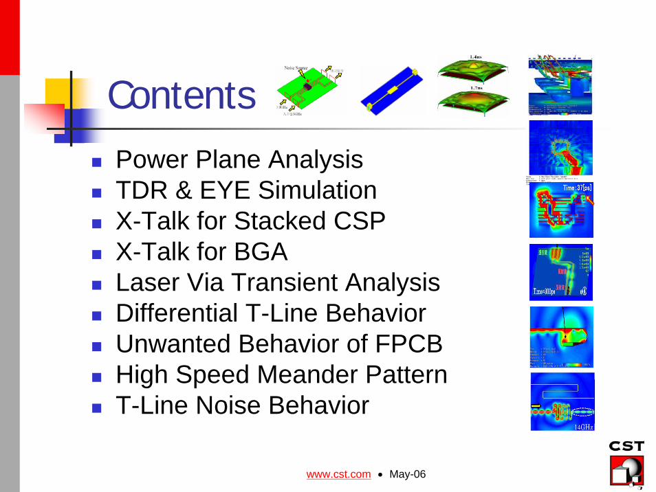
Contents
Power Plane AnalysisTDR & EYE SimulationX-Talk for Stacked CSPX-Talk for BGALaser Via Transient AnalysisDifferential T-Line BehaviorUnwanted Behavior of FPCBHigh Speed Meander PatternT-Line Noise Behavior
www.cst.com • May-06
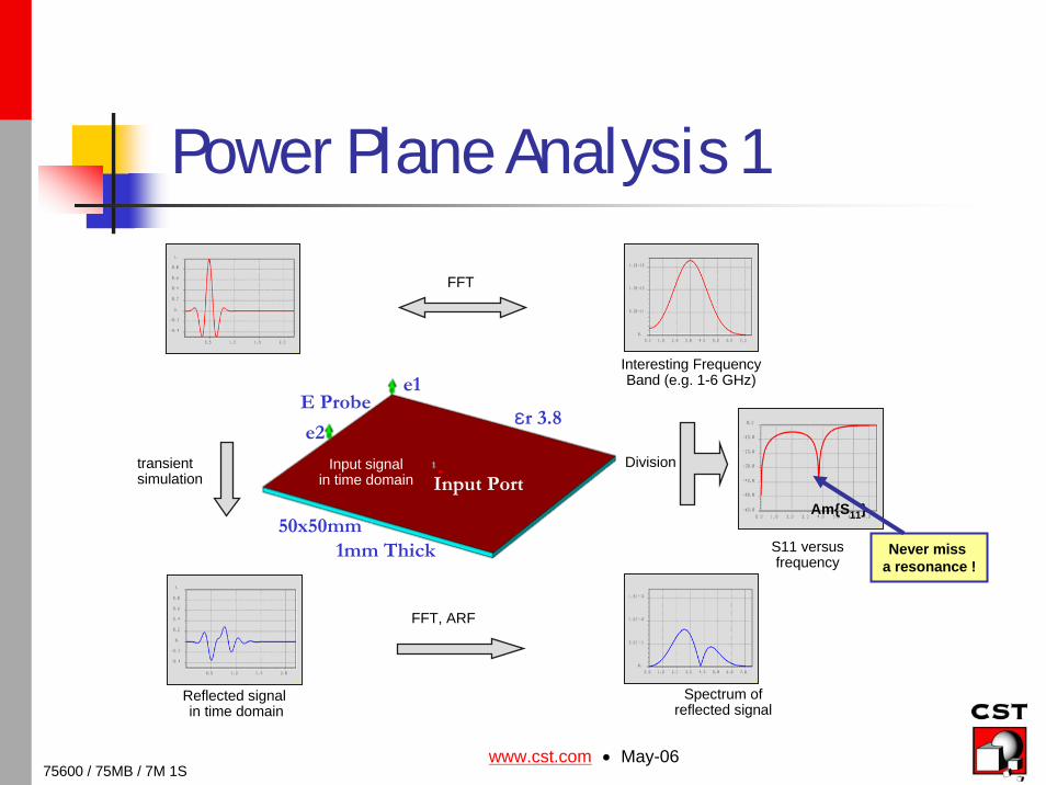
Power Plane Analysis 1
E Probee1
e2
50x50mm1mm Thick
εr 3.8
Input Port
75600 / 75MB / 7M 1S
Am{S11}
S11 versusfrequency
Division
Interesting FrequencyBand (e.g. 1-6 GHz)
Input signalin time domain
FFT
transientsimulation
Reflected signalin time domain
FFT, ARF
Spectrum of reflected signal
Never miss a resonance !
www.cst.com • May-06
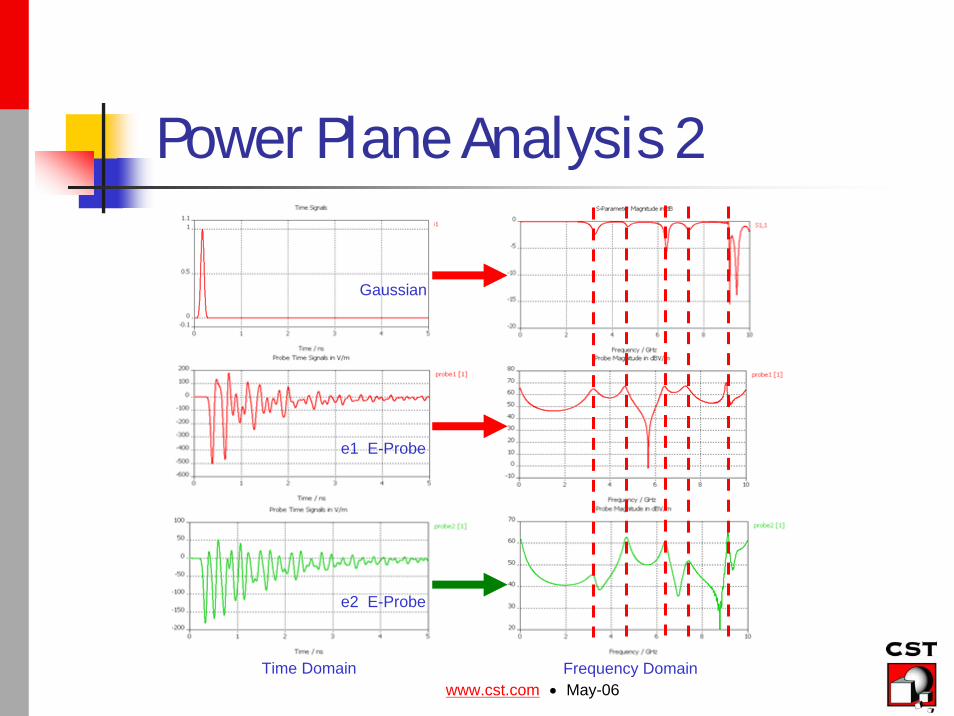
Power Plane Analysis 2
e1 E-Probe
e2 E-Probe
Time Domain
Gaussian
Frequency Domain
www.cst.com • May-06
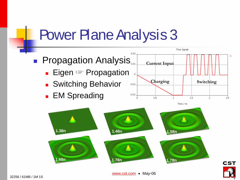
Power Plane Analysis 3
Propagation AnalysisEigen ☞ PropagationSwitching BehaviorEM Spreading
Current Input
Charging Switching
1.38n 1.48n 1.58n
1.68n 1.78n 1.78n
32256 / 61MB / 1M 1S
www.cst.com • May-06
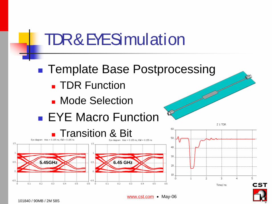
TDR & EYE Simulation
Template Base PostprocessingTDR FunctionMode Selection
EYE Macro FunctionTransition & Bit
101840 / 90MB / 2M 58S
5.45GHz 6.45 GHz
www.cst.com • May-06
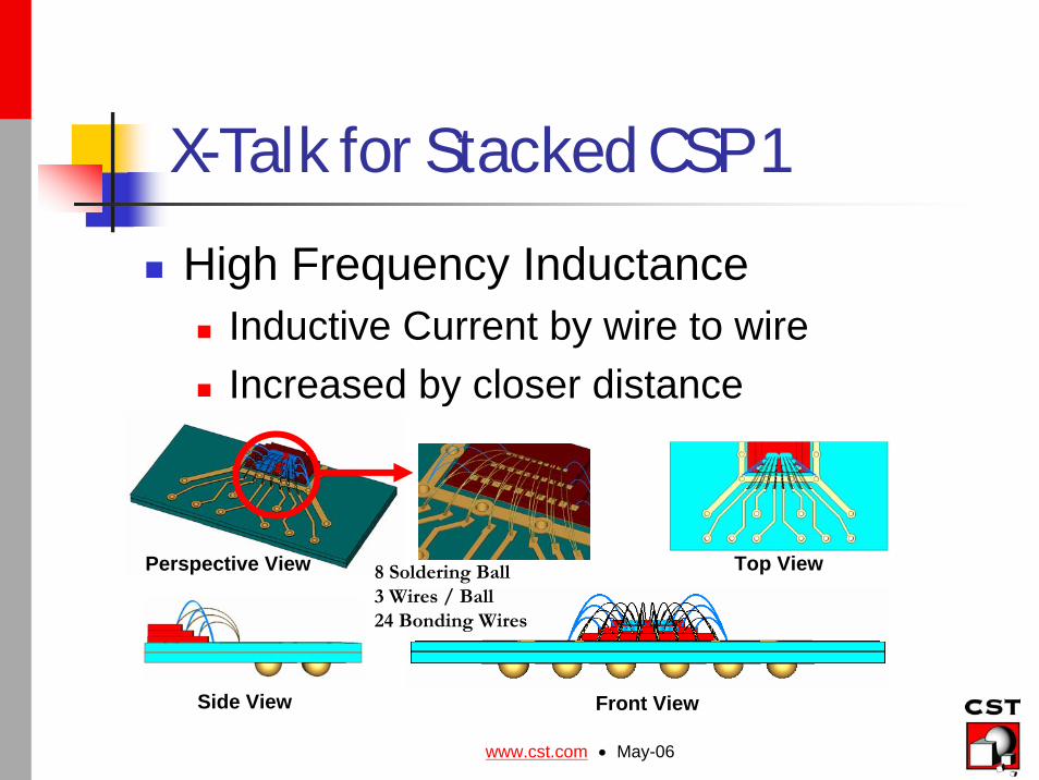
X-Talk for Stacked CSP 1
High Frequency InductanceInductive Current by wire to wireIncreased by closer distance
Perspective View Top View
Front ViewSide View
8 Soldering Ball3 Wires / Ball24 Bonding Wires
www.cst.com • May-06
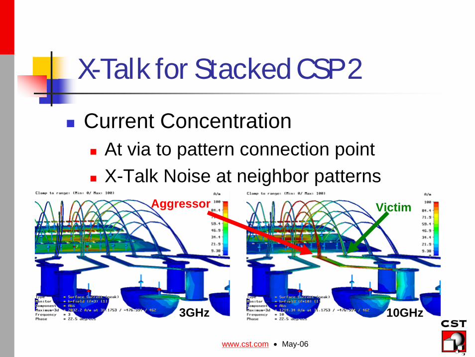
X-Talk for Stacked CSP 2
Current ConcentrationAt via to pattern connection pointX-Talk Noise at neighbor patterns
3GHz 10GHz
VictimAggressor
www.cst.com • May-06
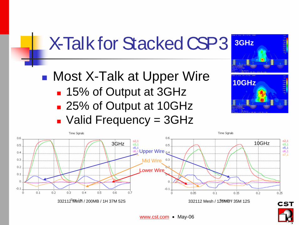
X-Talk for Stacked CSP 3
Most X-Talk at Upper Wire15% of Output at 3GHz25% of Output at 10GHzValid Frequency = 3GHz
3GHz
10GHz
3GHz 10GHz
332112 Mesh / 126MB / 35M 12S332112 Mesh / 200MB / 1H 37M 52S
Upper Wire
Mid Wire
Lower Wire
www.cst.com • May-06
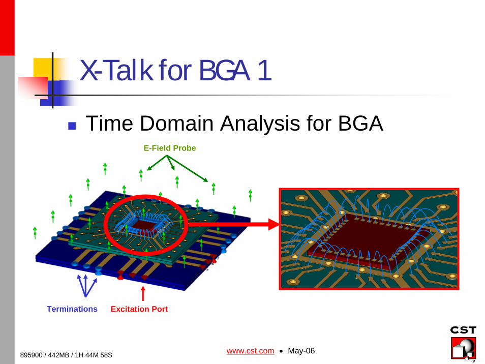
X-Talk for BGA 1
Time Domain Analysis for BGAE-Field Probe
Excitation PortTerminations
895900 / 442MB / 1H 44M 58S
www.cst.com • May-06
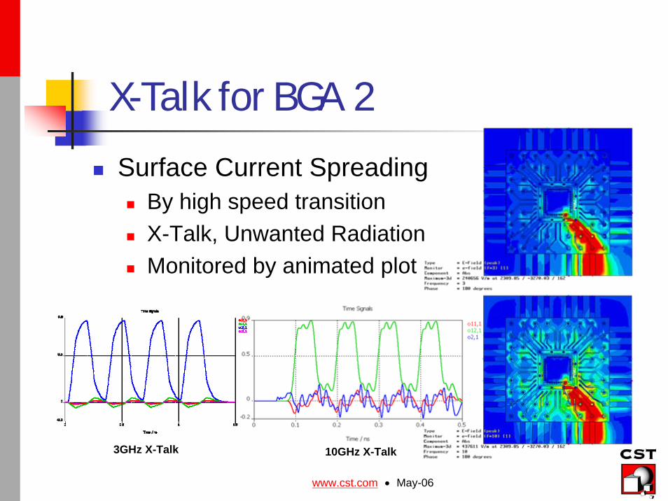
X-Talk for BGA 2
Surface Current SpreadingBy high speed transitionX-Talk, Unwanted RadiationMonitored by animated plot
3GHz X-Talk 10GHz X-Talk
www.cst.com • May-06
Laser Via Transient Analysis 1
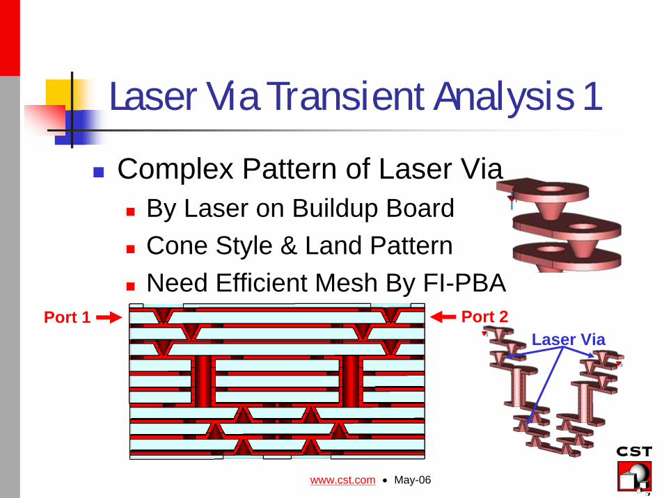
Complex Pattern of Laser ViaBy Laser on Buildup BoardCone Style & Land PatternNeed Efficient Mesh By FI-PBA
Port 1 Port 2Laser Via
www.cst.com • May-06
Laser Via Transient Analysis 2
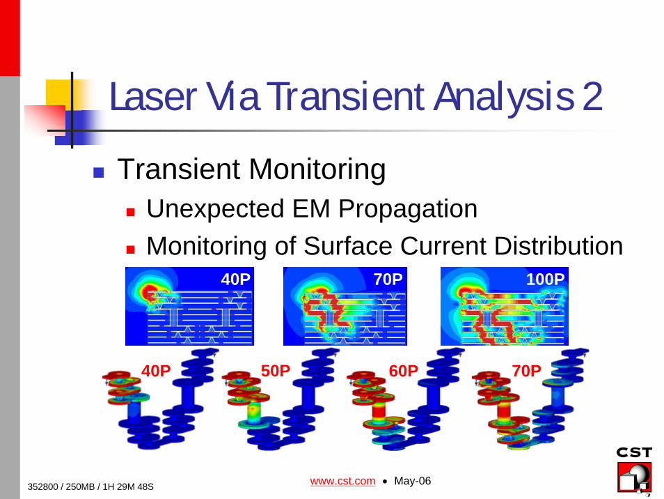
Transient MonitoringUnexpected EM PropagationMonitoring of Surface Current Distribution
40P 70P 100P
40P 50P 60P 70P
352800 / 250MB / 1H 29M 48S
www.cst.com • May-06
Differential T-Line Behavior
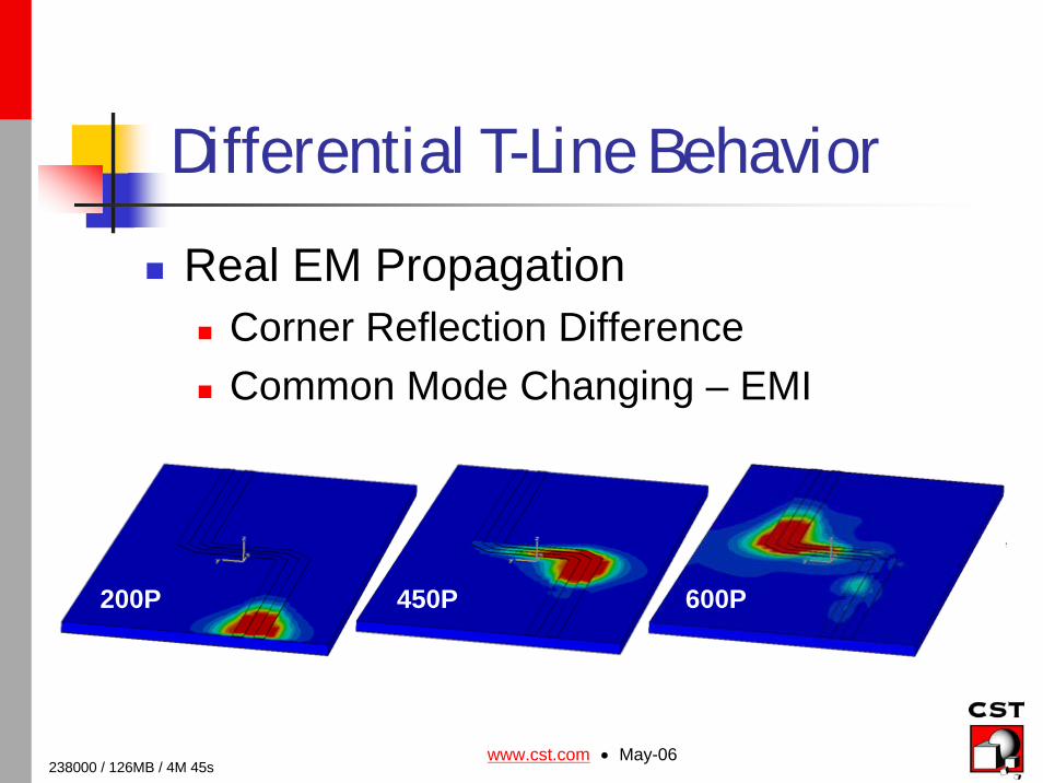
Real EM PropagationCorner Reflection DifferenceCommon Mode Changing – EMI
200P 450P 600P
238000 / 126MB / 4M 45s
www.cst.com • May-06
Unwanted Behavior of FPCB
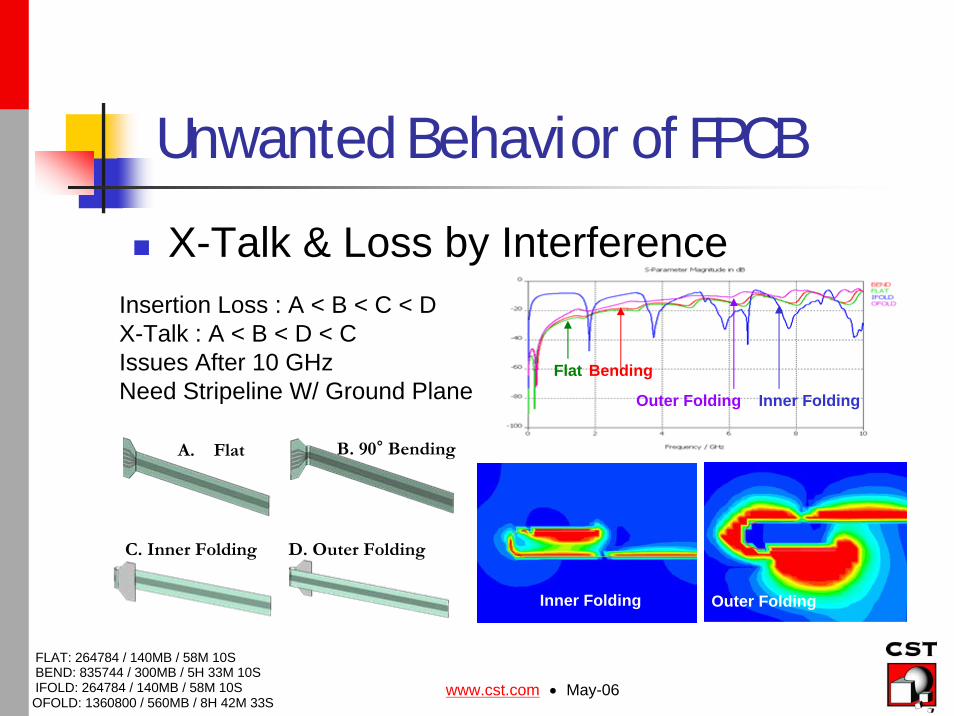
X-Talk & Loss by InterferenceInsertion Loss : A < B < C < DX-Talk : A < B < D < C Issues After 10 GHzNeed Stripeline W/ Ground Plane
B. 90° BendingA. Flat
D. Outer FoldingC. Inner Folding
FLAT: 264784 / 140MB / 58M 10SBEND: 835744 / 300MB / 5H 33M 10SIFOLD: 264784 / 140MB / 58M 10SOFOLD: 1360800 / 560MB / 8H 42M 33S
Flat Bending
Inner FoldingOuter Folding
Inner Folding Outer Folding
www.cst.com • May-06
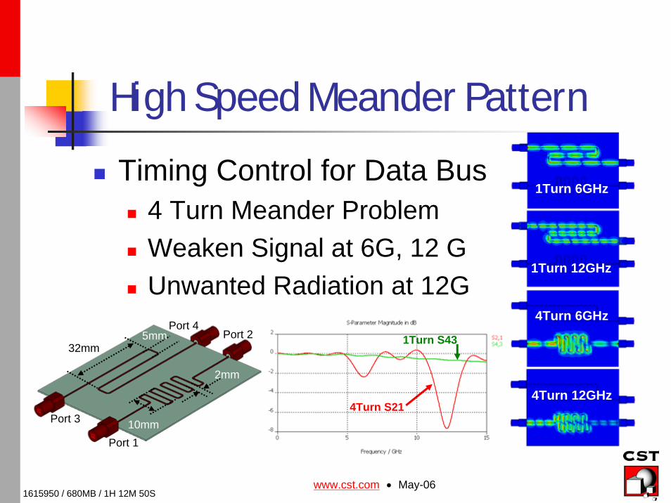
High Speed Meander Pattern
Timing Control for Data Bus4 Turn Meander ProblemWeaken Signal at 6G, 12 GUnwanted Radiation at 12G
5mm32mm
10mm
2mm
Port 1
Port 2Port 4
Port 3
1Turn 6GHz
1Turn 12GHz
4Turn 6GHz
4Turn 12GHz4Turn S21
1615950 / 680MB / 1H 12M 50S
1Turn S43
www.cst.com • May-06
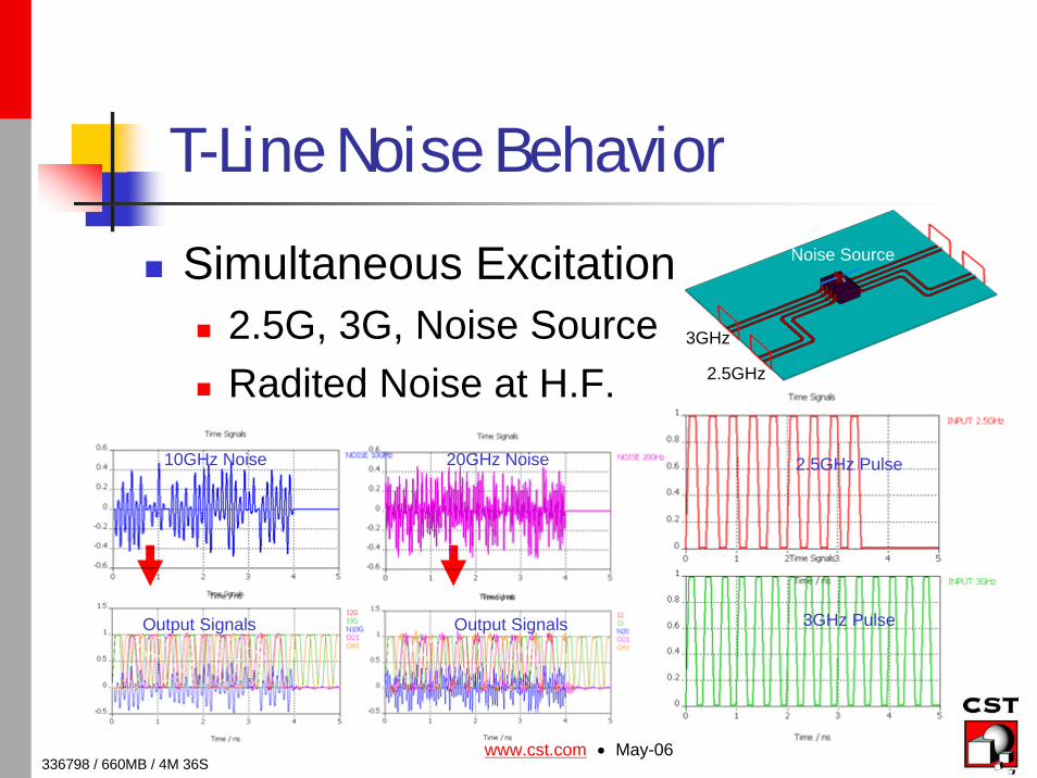
T-Line Noise Behavior
Simultaneous Excitation2.5G, 3G, Noise SourceRadited Noise at H.F. 2.5GHz
3GHz
Noise Source
10GHz Noise 20GHz Noise
Output Signals Output Signals
336798 / 660MB / 4M 36S
2.5GHz Pulse
3GHz Pulse
www.cst.com • May-06
Conclusions 1
Real X-Talk by Transient AnalysisCSP / BGA by Pulse Excitation
Transient Monitoring by Animated PlotUnwanted Radiation / Surface CurrentLaser Via Complex Pattern – FI-PBA
Mode Changing by ReflectionDifferential Mode to Common Mode – EMI
Interference and Radiation of FPCBX-Talk by High Speed Pulse Set Excitation
www.cst.com • May-06
Conclusions 2
No More MeanderNo More Signal Propagation and Why & Where
Simultaneous SwitchingSignal Propagation with External Noise
TDR SimulationGet Easy Clue About Impedance Mismatching
Wave Propagation of Power Plane Eigen Mode for RadiationSignal Propagation Through Conductor Path