Ward Leonard Motor-Generator Set - WordPress.com...Ward Leonard Motor-Generator Set Objective To...
2
Ward Leonard Motor-Generator Set Objective To control the speed of a DC motor using a Ward Leonard motor-generator set. Apparatus 1. 3 x FHP 12V DC motors with separate field connections 2. 4 mm leads 3. 56 Ω rheostat connected as a potentiometer 4. Reversing switch 5. Rubber tube to connect pair of motors 6. Unilab PSU Method 1. Couple two of the motors using the rubber tube. 2. Set the PSU to 15V 3. Set the switch to its central position (OFF). 4. Set the rheostat to minimum. 5. Connect the components as shown in the schematic, bear in mind that high currents flow in the armature connections, so arrange these leads to minimise voltage drop. 6. Switch ON. 7. Move the reversing switch to one direction. 8. Increase the speed by slowly moving the rheostat to the maximum position. 9. Decrease the speed to zero by moving the rheostat to the minimum position. 10. Move the reversing switch to the opposite direction. 11. Increase and decrease the speed as before.
Transcript of Ward Leonard Motor-Generator Set - WordPress.com...Ward Leonard Motor-Generator Set Objective To...
Ward Leonard Motor-Generator Set
Objective
To control the speed of a DC motor using a Ward Leonard motor-generator set.
Apparatus
1. 3 x FHP 12V DC motors with separate field connections
2. 4 mm leads
3. 56 Ω rheostat connected as a potentiometer
4. Reversing switch
5. Rubber tube to connect pair of motors
6. Unilab PSU
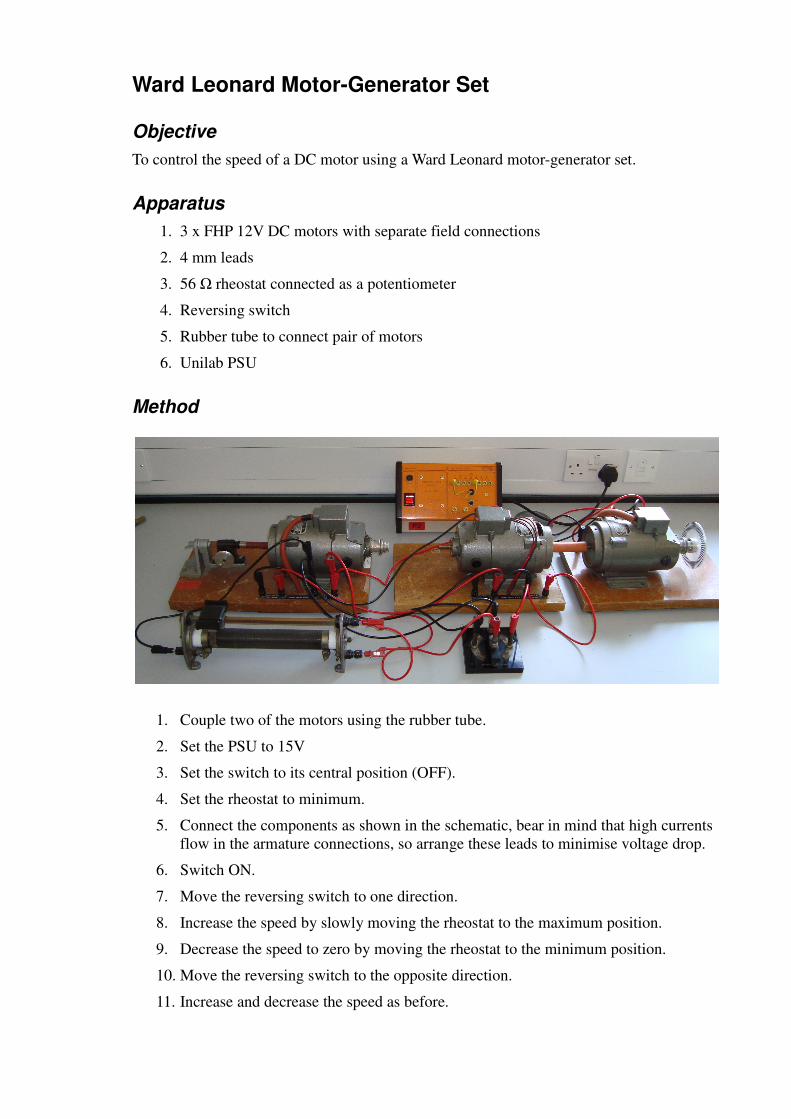
Method
1. Couple two of the motors using the rubber tube.
2. Set the PSU to 15V
3. Set the switch to its central position (OFF).
4. Set the rheostat to minimum.
5. Connect the components as shown in the schematic, bear in mind that high currents
flow in the armature connections, so arrange these leads to minimise voltage drop.
6. Switch ON.
7. Move the reversing switch to one direction.
8. Increase the speed by slowly moving the rheostat to the maximum position.
9. Decrease the speed to zero by moving the rheostat to the minimum position.
10. Move the reversing switch to the opposite direction.
11. Increase and decrease the speed as before.
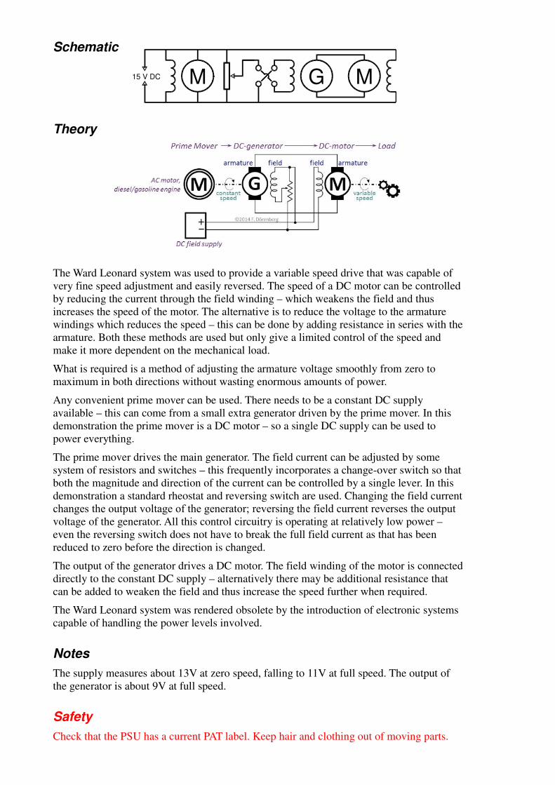
Schematic
Theory
The Ward Leonard system was used to provide a variable speed drive that was capable of
very fine speed adjustment and easily reversed. The speed of a DC motor can be controlled
by reducing the current through the field winding – which weakens the field and thus
increases the speed of the motor. The alternative is to reduce the voltage to the armature
windings which reduces the speed – this can be done by adding resistance in series with the
armature. Both these methods are used but only give a limited control of the speed and
make it more dependent on the mechanical load.
What is required is a method of adjusting the armature voltage smoothly from zero to
maximum in both directions without wasting enormous amounts of power.
Any convenient prime mover can be used. There needs to be a constant DC supply
available – this can come from a small extra generator driven by the prime mover. In this
demonstration the prime mover is a DC motor – so a single DC supply can be used to
power everything.
The prime mover drives the main generator. The field current can be adjusted by some
system of resistors and switches – this frequently incorporates a change-over switch so that
both the magnitude and direction of the current can be controlled by a single lever. In this
demonstration a standard rheostat and reversing switch are used. Changing the field current
changes the output voltage of the generator; reversing the field current reverses the output
voltage of the generator. All this control circuitry is operating at relatively low power –
even the reversing switch does not have to break the full field current as that has been
reduced to zero before the direction is changed.
The output of the generator drives a DC motor. The field winding of the motor is connected
directly to the constant DC supply – alternatively there may be additional resistance that
can be added to weaken the field and thus increase the speed further when required.
The Ward Leonard system was rendered obsolete by the introduction of electronic systems
capable of handling the power levels involved.
Notes
The supply measures about 13V at zero speed, falling to 11V at full speed. The output of
the generator is about 9V at full speed.
Safety
Check that the PSU has a current PAT label. Keep hair and clothing out of moving parts.
M15 V DC G M