
UPDATE OF THE MECHANICAL DESIGN OF THE 650 MHZ …
3
UPDATE OF THE MECHANICAL DESIGN OF THE 650 MHZ ΒETA=0.9 CAVITIES FOR PROJECT X* I. Gonin # , M. Awida, E. Borissov, M. Foley, C. Grimm, T. Khabiboulline, Y. Pischalnikov, V. Yakovlev, FNAL, Batavia, IL 60510, USA Abstract The design of 5-cell elliptical 650 MHz β=0.9 cavities to accelerate 1 mA at an average H-beam current in the range 467-3000 MeV for Project X Linac [1] is under development at Fermilab. The design of a dressed cavity has been mechanically optimized by minimizing df/dP, the sensitivity to microphonics detuning due to fluctuations in helium pressure. We will present the results of COMSOL multiphysics simulations of mechanical resonances, Lorentz force detuning (LFD), and cavity tuneability. We will also present the mechanical design of slow and fast tuners and ANSYS analysis of their properties. INTRODUCTION The proposed design of the 3 GeV Project X Superconducting Linac employs two families of 650 MHz 5-cell elliptical cavities with different Beta versions. The β=0.61 will cover the 177-467 MeV range and the β=0.9 will cover the 467-3000 MeV range. Approximately 30 β=0.61 and 160 β=0.91 cavities are currently required for the project. The low beam current for CW operation of Project X requires cavities to be mechanically optimized to operate at a high loaded Q and thus, low bandwidth with higher sensitivity to microphonics. This paper will also present the finalized mechanical design of the Helium Vessel (HV) for β=0.91 cavities, which will assist in minimizing the magnitude of df/dP. The HV in the current design is equipped with the tuner located at the end of the cavity instead of the initially proposed blade tuner located in the middle [2]. We will also present the COMSOL simulations of mechanical resonances and Lorentz force detuning. HELIUM VESSEL DESIGN The helium vessel assembly is constructed from a single 5 mm thick sheet of grade 2 titanium that is rolled and seam welded into a tube with an inside diameter of 441 mm and a length of 930 mm. The helium vessel assembly is shown in Fig. 1. Figure 1: He vessel assembly The weld joint designs on the helium vessel satisfy the ASME Boiler & Pressure Vessel Code Section VIII Division 2. It is important to note that the 5 mm wall thickness for the helium vessel specification was not because of the ASME code, but rather to help in reducing df/dP by using the helium vessel to help stiffen the cavity. The main coupler end and the field probe end of the helium vessel have slightly different joint designs due to the cavity installation sequence and variations in cavity lengths. The main coupler end of the vessel is considered a fixed position relative to the main coupler port of the cavity, and consistency between these key features for dressed cavities is maintained. Fig. 2 shows the titanium- to-titanium TIG weld connection between the cavity and the helium vessel at the main coupler end. This joint design utilizes a backing ring and satisfies the ASME code. Figure 2: He vessel to cavity fixed joint design To allow for variations in the lengths of the manufactured cavities, the field probe end required a sliding joint design that would allow for cavity insertion from the field probe end to the main coupler end. As shown in Fig. 3, cavities that vary by ±10 mm in length will not have any effect on the vessel design. This joint also satisfies the ASME code. Figure 3: He vessel to cavity sliding joint design ___________________________________________ * Operated by Fermi Research Alliance, LLC, under Contract DE-AC02-07CH11359 with the U.S. DOE # [email protected] FERMILAB-CONF-13-138-TD
Transcript of UPDATE OF THE MECHANICAL DESIGN OF THE 650 MHZ …
UPDATE OF THE MECHANICAL DESIGN OF THE 650 MHZ ΒETA=0.9 CAVITIES FOR PROJECT X*
I. Gonin#, M. Awida, E. Borissov, M. Foley, C. Grimm, T. Khabiboulline, Y. Pischalnikov, V. Yakovlev, FNAL, Batavia, IL 60510, USA
Abstract The design of 5-cell elliptical 650 MHz β=0.9 cavities
to accelerate 1 mA at an average H-beam current in the range 467-3000 MeV for Project X Linac [1] is under development at Fermilab. The design of a dressed cavity has been mechanically optimized by minimizing df/dP, the sensitivity to microphonics detuning due to fluctuations in helium pressure. We will present the results of COMSOL multiphysics simulations of mechanical resonances, Lorentz force detuning (LFD), and cavity tuneability. We will also present the mechanical design of slow and fast tuners and ANSYS analysis of their properties.
INTRODUCTION The proposed design of the 3 GeV Project X
Superconducting Linac employs two families of 650 MHz 5-cell elliptical cavities with different Beta versions. The β=0.61 will cover the 177-467 MeV range and the β=0.9 will cover the 467-3000 MeV range. Approximately 30 β=0.61 and 160 β=0.91 cavities are currently required for the project. The low beam current for CW operation of Project X requires cavities to be mechanically optimized to operate at a high loaded Q and thus, low bandwidth with higher sensitivity to microphonics.
This paper will also present the finalized mechanical design of the Helium Vessel (HV) for β=0.91 cavities, which will assist in minimizing the magnitude of df/dP. The HV in the current design is equipped with the tuner located at the end of the cavity instead of the initially proposed blade tuner located in the middle [2]. We will also present the COMSOL simulations of mechanical resonances and Lorentz force detuning.
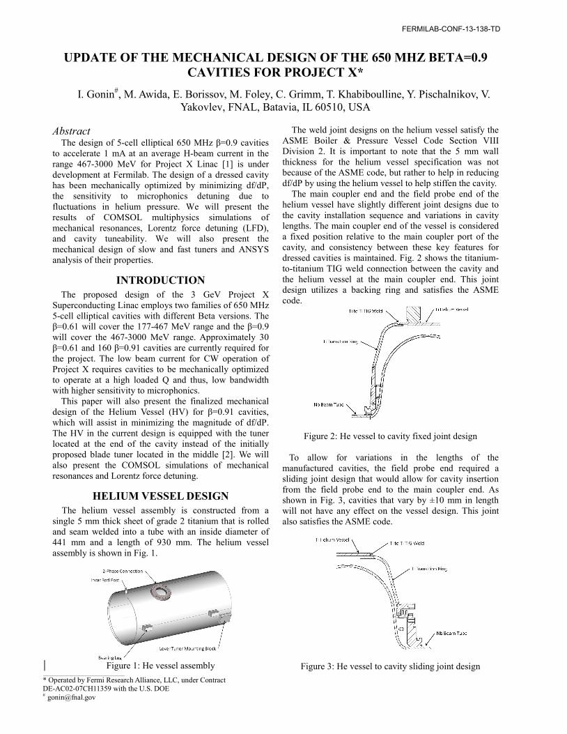
HELIUM VESSEL DESIGN The helium vessel assembly is constructed from a single 5 mm thick sheet of grade 2 titanium that is rolled and seam welded into a tube with an inside diameter of 441 mm and a length of 930 mm. The helium vessel assembly is shown in Fig. 1.
Figure 1: He vessel assembly
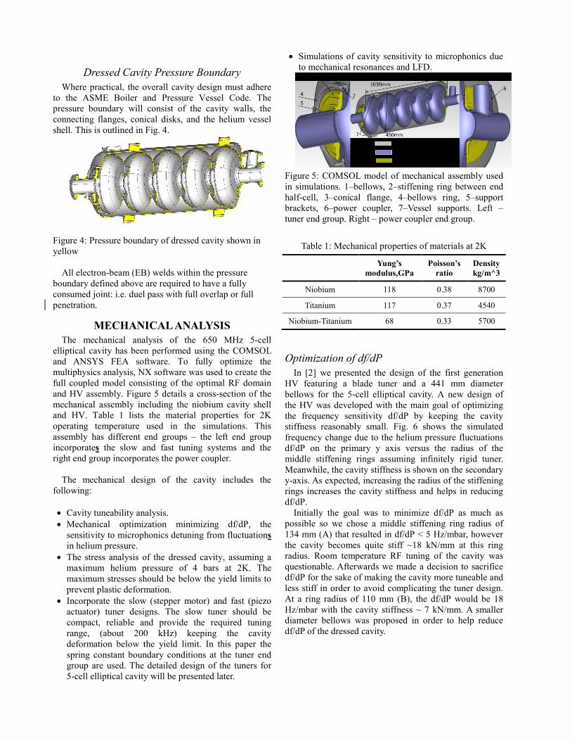
The weld joint designs on the helium vessel satisfy the ASME Boiler & Pressure Vessel Code Section VIII Division 2. It is important to note that the 5 mm wall thickness for the helium vessel specification was not because of the ASME code, but rather to help in reducing df/dP by using the helium vessel to help stiffen the cavity. The main coupler end and the field probe end of the helium vessel have slightly different joint designs due to the cavity installation sequence and variations in cavity lengths. The main coupler end of the vessel is considered a fixed position relative to the main coupler port of the cavity, and consistency between these key features for dressed cavities is maintained. Fig. 2 shows the titanium-to-titanium TIG weld connection between the cavity and the helium vessel at the main coupler end. This joint design utilizes a backing ring and satisfies the ASME code.
Figure 2: He vessel to cavity fixed joint design
To allow for variations in the lengths of the manufactured cavities, the field probe end required a sliding joint design that would allow for cavity insertion from the field probe end to the main coupler end. As shown in Fig. 3, cavities that vary by ±10 mm in length will not have any effect on the vessel design. This joint also satisfies the ASME code.
Figure 3: He vessel to cavity sliding joint design ___________________________________________
* Operated by Fermi Research Alliance, LLC, under Contract DE-AC02-07CH11359 with the U.S. DOE # [email protected]
FERMILAB-CONF-13-138-TD
Dressed Cavity Pressure Boundary
Where practical, the overall cavity design must adhere to the ASME Boiler and Pressure Vessel Code. The pressure boundary will consist of the cavity walls, the connecting flanges, conical disks, and the helium vessel shell. This is outlined in Fig. 4.
Figure 4: Pressure boundary of dressed cavity shown in yellow All electron-beam (EB) welds within the pressure boundary defined above are required to have a fully consumed joint: i.e. duel pass with full overlap or full penetration.
MECHANICAL ANALYSIS The mechanical analysis of the 650 MHz 5-cell
elliptical cavity has been performed using the COMSOL and ANSYS FEA software. To fully optimize the multiphysics analysis, NX software was used to create the full coupled model consisting of the optimal RF domain and HV assembly. Figure 5 details a cross-section of the mechanical assembly including the niobium cavity shell and HV. Table 1 lists the material properties for 2K operating temperature used in the simulations. This assembly has different end groups – the left end group incorporates the slow and fast tuning systems and the right end group incorporates the power coupler.
The mechanical design of the cavity includes the
following: • Cavity tuneability analysis. • Mechanical optimization minimizing df/dP, the
sensitivity to microphonics detuning from fluctuations in helium pressure.
• The stress analysis of the dressed cavity, assuming a maximum helium pressure of 4 bars at 2K. The maximum stresses should be below the yield limits to prevent plastic deformation.
• Incorporate the slow (stepper motor) and fast (piezo actuator) tuner designs. The slow tuner should be compact, reliable and provide the required tuning range, (about 200 kHz) keeping the cavity deformation below the yield limit. In this paper the spring constant boundary conditions at the tuner end group are used. The detailed design of the tuners for 5-cell elliptical cavity will be presented later.
• Simulations of cavity sensitivity to microphonics due to mechanical resonances and LFD.
Figure 5: COMSOL model of mechanical assembly used in simulations. 1–bellows, 2–stiffening ring between end half-cell, 3–conical flange, 4–bellows ring, 5–support brackets, 6–power coupler, 7–Vessel supports. Left – tuner end group. Right – power coupler end group.
Table 1: Mechanical properties of materials at 2K
Yung’s modulus,GPa
Poisson’s ratio
Density kg/m^3
Niobium 118 0.38 8700
Titanium 117 0.37 4540
Niobium-Titanium 68 0.33 5700
Optimization of df/dP In [2] we presented the design of the first generation
HV featuring a blade tuner and a 441 mm diameter bellows for the 5-cell elliptical cavity. A new design of the HV was developed with the main goal of optimizing the frequency sensitivity df/dP by keeping the cavity stiffness reasonably small. Fig. 6 shows the simulated frequency change due to the helium pressure fluctuations df/dP on the primary y axis versus the radius of the middle stiffening rings assuming infinitely rigid tuner. Meanwhile, the cavity stiffness is shown on the secondary y-axis. As expected, increasing the radius of the stiffening rings increases the cavity stiffness and helps in reducing df/dP.
Initially the goal was to minimize df/dP as much as possible so we chose a middle stiffening ring radius of 134 mm (A) that resulted in df/dP < 5 Hz/mbar, however the cavity becomes quite stiff ~18 kN/mm at this ring radius. Room temperature RF tuning of the cavity was questionable. Afterwards we made a decision to sacrifice df/dP for the sake of making the cavity more tuneable and less stiff in order to avoid complicating the tuner design. At a ring radius of 110 mm (B), the df/dP would be 18 Hz/mbar with the cavity stiffness ~ 7 kN/mm. A smaller diameter bellows was proposed in order to help reduce df/dP of the dressed cavity.
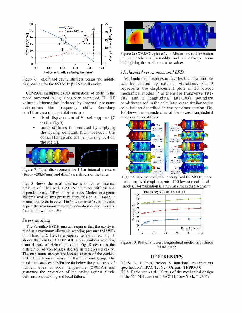
Figure 6: df/dP and cavity stiffness versus the middle ring position for the 650 MHz β=0.9 5-cell cavity.
COMSOL multiphysics 3D simulations of df/dP in the model presented in Fig. 7 has been completed. The RF volume deformation induced by internal pressure determines the frequency shift. Boundary conditions used in calculations are:
• fixed displacement of Vessel supports (7 on the Fig. 5)
• tuner stiffness is simulated by applying the spring constant Ktuner between the conical flange and the bellows ring (3, 4 on the Fig. 5).
Figure 7: Total displacement for 1 bar internal pressure (Ktuner =20kN/mm) and df/dP vs. stiffness of the tuner
Fig. 3 shows the total displacements for an internal pressure of 1 bar with a 20 kN/mm tuner stiffness and dependence of df/dP vs. tuner stiffness. Modern cryogenic systems achieve rms pressure stabilities of ~0.2 mbar. It means, that even in case of infinite tuner stiffness, one can expect the maximum frequency deviation due to pressure fluctuation will be <4Hz.
Stress analysis
The Fermilab ES&H manual requires that the cavity is rated at a maximum allowable working pressure (MAWP) of 4 bars at 2 Kelvin cryogenic temperatures. Fig. 8 shows the results of COMSOL stress analysis resulting from 4 bars of Helium pressure. Fig. 8 describes the distribution of von Misses stresses in the dressed cavity. The maximum stresses are located at area of the conical disk of the titanium vessel in the tuner end group. The maximum stresses 64MPa are far below the yield stress of titanium even in room temperature (270MPa) and guarantee the protection of the cavity against plastic deformation, buckling and local failure.
Figure 8: COMSOL plot of von Misses stress distribution in the mechanical assembly and an enlarged view highlighting the maximum stress values.
Mechanical resonances and LFD
Mechanical resonances of cavities in a cryomodule can be excited by external vibrations. Fig. 9 represents the displacement plots of 10 lowest mechanical modes (7 of them are transverse T#1-T#7 and 3 longitudinal L#1-L#3). Boundary conditions used in the calculations are similar to the calculations described in the previous section. Fig. 10 shows the dependencies of the lowest longitudinal modes vs. tuner stiffness.
Figure 9: Frequencies, total energy, and COMSOL plots of normalized displacements of 10 lowest mechanical
modes. Normalization is 1mm maximum displacement.
Figure 10: Plot of 3 lowest longitudinal modes vs stiffness of the tuner
REFERENCES [1] S. D. Holmes,”Project X functional requirements specification”, IPAC’12, New Orleans, THPPP090. [2] S. Barbanotti et al., “Status of the mechanical design of the 650 MHz cavities”, PAC’11, New York, TUP069.


![Multipacting in PIP-II 650 MHz.pptx [Read-Only]pxie.fnal.gov/PIPIImeetings/MultipactingInPIP-II_650MHz.pdf · Exponential growth rate 3 G.Romanov | Multipacting in PIP-II 650 MHz](https://static.fdocument.org/doc/165x107/5b8145247f8b9a466b8bfbbb/multipacting-in-pip-ii-650-mhzpptx-read-onlypxiefnalgovpipiimeetingsmultipactinginpip-ii.jpg)