Oxidative stress and changes in the content and pattern of ...
• ΜΑΡΝΗ 8 ΑΘΗΝΑ 10433 • ΤΗΛ. 210 3845676 – 210 3845272 FAX. 210 3809747 • e-mail: [email protected] •
McIntosh Laboratory, Inc. 2 Chambers Street Binghamton, New York 13903-2699 Phone: 607-723-3512 www.mcintoshlabs.com
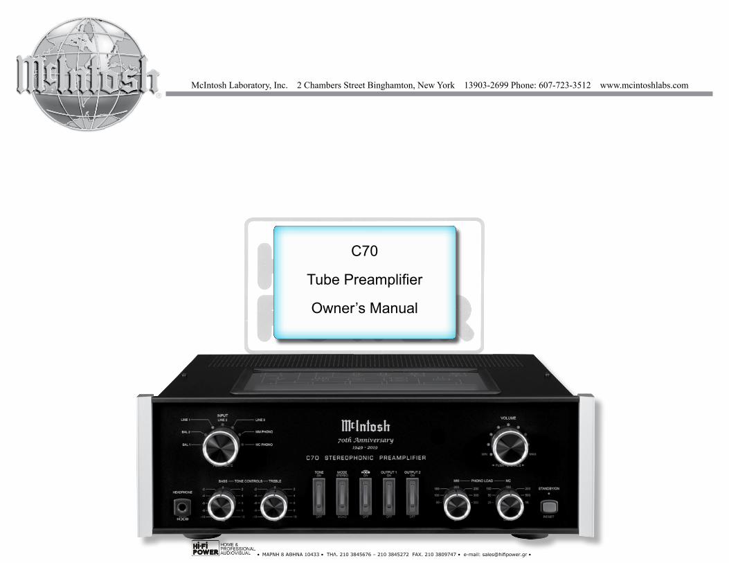
C70
Tube Preamplifier
Owner’s Manual
• ΜΑΡΝΗ 8 ΑΘΗΝΑ 10433 • ΤΗΛ. 210 3845676 – 210 3845272 FAX. 210 3809747 • e-mail: [email protected] •
2
Your decision to own this McIntosh C70 Stereophonic Preamplifier with Tube Circuitry ranks you at the very top among discriminating music listeners. You now have “The Best.” The McIntosh dedication to “Qual-ity,” is assurance that you will receive many years of musical enjoyment from this unit.Please take a short time to read the information in this manual. We want you to be as familiar as pos-sible with all the features and functions of your new McIntosh.
Copyright 2018 © by McIntosh Laboratory, Inc.
Table of ContentsThank You
Please Take A Moment
Technical AssistanceIf at any time you have questions about your McIntosh product, contact your McIntosh Dealer who is familiar with your McIntosh equipment and any other brands that may be part of your system. If you or your Dealer wish additional help concerning a suspected problem, you can receive technical assistance for all McIntosh products at:
McIntosh Laboratory, Inc.2 Chambers StreetBinghamton, New York 13903Phone: 607-723-3512Fax: 607-724-0549
Customer ServiceIf it is determined that your McIntosh product is in need of repair, you can return it to your Dealer. You can also return it to the McIntosh Laboratory Service Department. For assistance on factory repair return procedure, contact the McIntosh Service Department at:McIntosh Laboratory, Inc.2 Chambers StreetBinghamton, New York 13903Phone: 607-723-3515Fax: 607-723-1917
The serial number, purchase date and McIntosh Dealer name are important to you for possible insurance claim or future service. The spaces below have been provided for you to record that information:
Serial Number: _______________________________
Purchase Date: _______________________________
Dealer Name: ________________________________
Important Safety Information is supplied in a separate document “Important Additional Operation Information Guide”
Safety Instructions ..................................................... 2 (Separate Sheet) ................... Important Additional
Operation Information GuideThank You and Please Take a Moment ....................... 2Technical Assistance and Customer Service .............. 2Table of Contents ........................................................ 2General Information ................................................... 3Connector and Cable Information ..............................3Introduction .................................................................4Performance Features .................................................4Dimensions .................................................................5Installation ..................................................................6Rear Panel Connections ............................................. 7How to Connect the C70 ............................................ 8Connection Diagrams (Separate Sheets).... Mc1A and Mc1BHow to use the Remote Control .......................... 10-11Front Panel Displays, Controls, Switchesand Jack .................................................................... 12How to Operate the C70 ..................................... 13-14Photos .................................................................. 15-17Specifications ........................................................... 18Packing Instruction .................................................. 19
• ΜΑΡΝΗ 8 ΑΘΗΝΑ 10433 • ΤΗΛ. 210 3845676 – 210 3845272 FAX. 210 3809747 • e-mail: [email protected] •
3
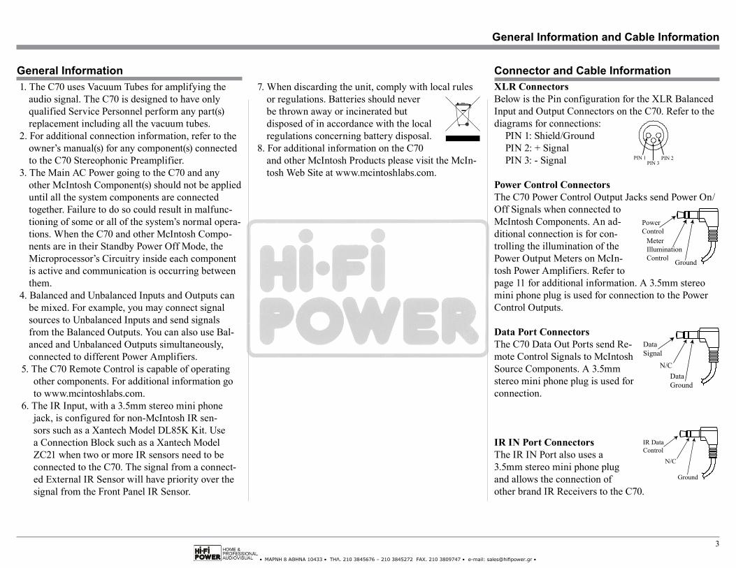
XLR ConnectorsBelow is the Pin configuration for the XLR Balanced Input and Output Connectors on the C70. Refer to the diagrams for connections:
PIN 1: Shield/GroundPIN 2: + SignalPIN 3: - Signal
Power Control ConnectorsThe C70 Power Control Output Jacks send Power On/Off Signals when connected to McIntosh Components. An ad-ditional connection is for con-trolling the illumination of the Power Output Meters on McIn-tosh Power Amplifiers. Refer to page 11 for additional information. A 3.5mm stereo mini phone plug is used for connection to the Power Control Outputs.
Data Port ConnectorsThe C70 Data Out Ports send Re-mote Control Signals to McIntosh Source Components. A 3.5mm stereo mini phone plug is used for connection.
IR IN Port ConnectorsThe IR IN Port also uses a 3.5mm stereo mini phone plug and allows the connection of other brand IR Receivers to the C70.
1. The C70 uses Vacuum Tubes for amplifying the audio signal. The C70 is designed to have only qualified Service Personnel perform any part(s) replacement including all the vacuum tubes.
2. For additional connection information, refer to the owner’s manual(s) for any component(s) connected to the C70 Stereophonic Preamplifier.
3. The Main AC Power going to the C70 and any other McIntosh Component(s) should not be applied until all the system components are connected together. Failure to do so could result in malfunc-tioning of some or all of the system’s normal opera-tions. When the C70 and other McIntosh Compo-nents are in their Standby Power Off Mode, the Microprocessor’s Circuitry inside each component is active and communication is occurring between them.
4. Balanced and Unbalanced Inputs and Outputs can be mixed. For example, you may connect signal sources to Unbalanced Inputs and send signals from the Balanced Outputs. You can also use Bal-anced and Unbalanced Outputs simultaneously, connected to different Power Amplifiers.
5. The C70 Remote Control is capable of operating other components. For additional information goto www.mcintoshlabs.com.
6. The IR Input, with a 3.5mm stereo mini phone jack, is configured for non-McIntosh IR sen-sors such as a Xantech Model DL85K Kit. Use a Connection Block such as a Xantech Model ZC21 when two or more IR sensors need to be connected to the C70. The signal from a connect-ed External IR Sensor will have priority over the signal from the Front Panel IR Sensor.
General Information Connector and Cable Information
PIN 1 PIN 2PIN 3
DataSignal
N/CDataGround
IR DataControl
Ground
N/C
7. When discarding the unit, comply with local rulesor regulations. Batteries should neverbe thrown away or incinerated butdisposed of in accordance with the localregulations concerning battery disposal.
8. For additional information on the C70and other McIntosh Products please visit the McIn-tosh Web Site at www.mcintoshlabs.com.
General Information and Cable Information
PowerControl
MeterIlluminationControl Ground
• ΜΑΡΝΗ 8 ΑΘΗΝΑ 10433 • ΤΗΛ. 210 3845676 – 210 3845272 FAX. 210 3809747 • e-mail: [email protected] •
4
Introduction and Performance Features
Introduction
Performance Features
The McIntosh C70 Stereophonic Preamplifier is one of the finest Tube Preamplifiers ever created. The versatile Preamplifier provides connections for vari-ous input sources and outputs to drive multiple Power Amplifiers. The C70 reproduction is sonically trans-parent and absolutely accurate. The McIntosh Sound is “The Sound of the Music Itself.”
• Electromagentic Input SwitchingDigital Logic integrated circuits drive Electromagnet-ic Switches on all Inputs and operating functions for reliable, noiseless, distortion free switching.
• Moving Coil and Moving Magnet Phono InputsThe C70 contains two different precision Phono Pre-amplifier Circuits. One for low output Moving Coil Phono Cartridges with selectable resistance loading, the other is for Moving Magnet Cartridges with select-able capacitive loading. Both circuits use the latest de-signs to provide the lowest possible noise and distor-tion. The RIAA Equalization Circuitry utilizies close tolerance resistors and capacitors for an extremely flat frequency response.
• Balanced InputsThe Balanced Inputs allow the connection of a source component using long cable lengths without a loss in sound quality.
• Low DistortionDistortion levels of all types are less than 0.08%. Mu-sic is amplified with total transparency and accuracy.
• Variable Rate Volume and Balance ControlThe C70 Preamplifier’s Volume and Balance ControlCircuitry provides an ideal rate of change with controlrotation.
• Tone Controls with BypassThe C70 allows for bypassing the Bass and TrebleTone Circuitry.
• Output SwitchingFront panel Output Push-buttons control two SwitchedOutputs that allow sending signals to two separatePower Amplifiers.
• HXD® for HeadphonesThe C70 Headphone Crossfeed Director Circuitry(HXD® ) improves the sound localization for Head-phone Listening. HXDTM restores the directionalitycomponent of the spatial sound stage normally heardwith Loudspeaker listening.
• Remote ControlThe Remote Control provides basic control of the C70operating functions and any McIntosh Source Compo-nents connected to it.
• Power Control OutputA Power Control connection for convenient Turn-Onof McIntosh Power Amplifiers, Source Componentsand Accessories is included.
• Precision PartsOnly the finest precision 1% tolerance resistors areused throughout.
• Special Power SupplyFully regulated Power Supplies and a special R-CorePower Transformer ensure stable noise free operationeven though the power line varies.
• Solid State Front Panel IlluminationThe Illumination of the Front Panel is accomplishedby extra long life Light Emitting Diodes (LEDs).
• Glass Front Panel and Super Mirror ChassisFinish
The famous McIntosh Illuminated Glass Front Panel and the Lower Chassis are Stainless Steel with a Mir-ror Finish. The Upper Chassis and Top Cover has a glass window to view the amplifying vacuum tubes. This will ensure the pristine beauty of the C70 will be retained for many years to come.
• ΜΑΡΝΗ 8 ΑΘΗΝΑ 10433 • ΤΗΛ. 210 3845676 – 210 3845272 FAX. 210 3809747 • e-mail: [email protected] •
5
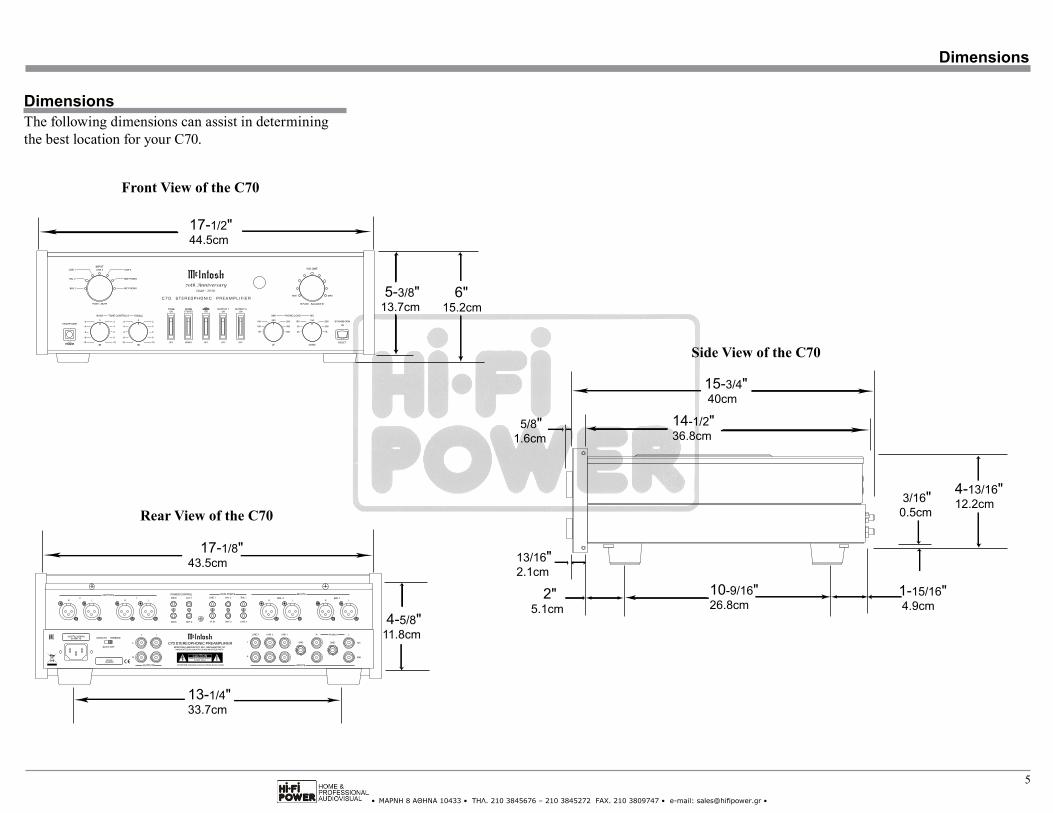
DimensionsThe following dimensions can assist in determining the best location for your C70.
Dimensions
Side View of the C70
Front View of the C70
Rear View of the C70
17-1/2"44.5cm
6"15.2cm
5-3/8"13.7cm
4-5/8"11.8cm
13-1/4"33.7cm
17-1/8"43.5cm
14-1/2"36.8cm
15-3/4"40cm
3/16"0.5cm
4-13/16"12.2cm
10-9/16"26.8cm
5/8"1.6cm
13/16"2.1cm
2"5.1cm
1-15/16"4.9cm
• ΜΑΡΝΗ 8 ΑΘΗΝΑ 10433 • ΤΗΛ. 210 3845676 – 210 3845272 FAX. 210 3809747 • e-mail: [email protected] •
6
Installation
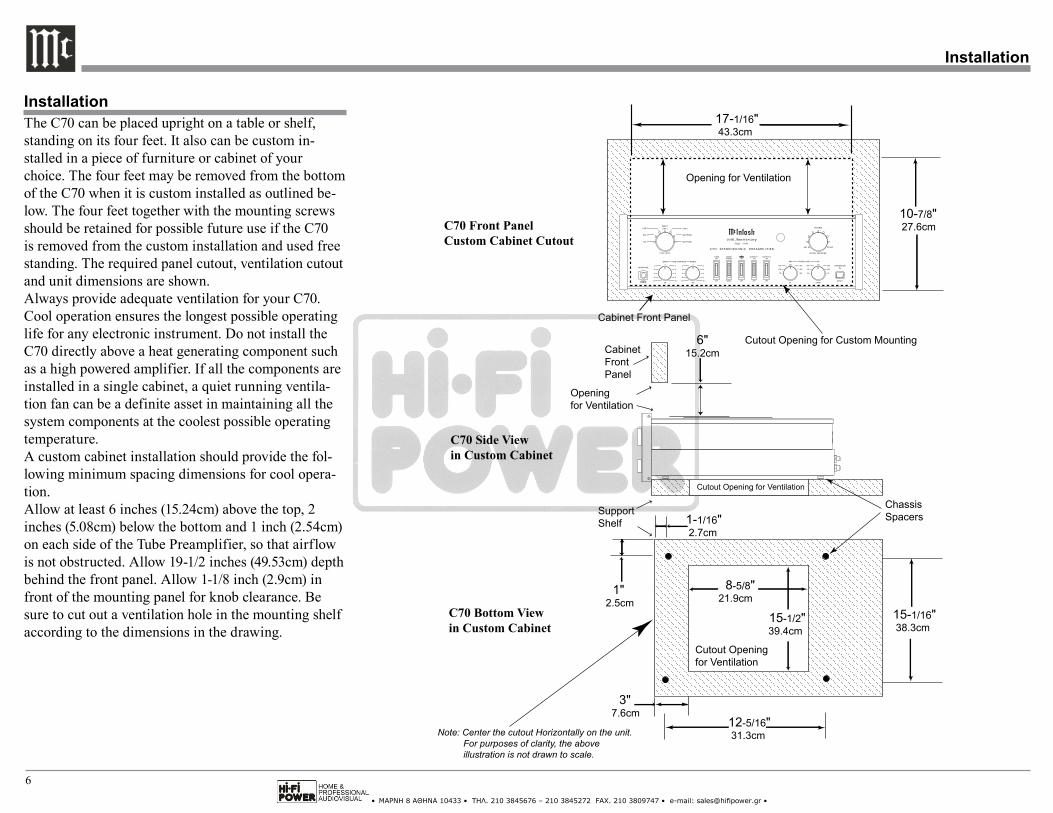
InstallationThe C70 can be placed upright on a table or shelf, standing on its four feet. It also can be custom in-stalled in a piece of furniture or cabinet of your choice. The four feet may be removed from the bottom of the C70 when it is custom installed as outlined be-low. The four feet together with the mounting screws should be retained for possible future use if the C70 is removed from the custom installation and used free standing. The required panel cutout, ventilation cutout and unit dimensions are shown.Always provide adequate ventilation for your C70. Cool operation ensures the longest possible operating life for any electronic instrument. Do not install the C70 directly above a heat generating component such as a high powered amplifier. If all the components are installed in a single cabinet, a quiet running ventila-tion fan can be a definite asset in maintaining all the system components at the coolest possible operating temperature.A custom cabinet installation should provide the fol-lowing minimum spacing dimensions for cool opera-tion.Allow at least 6 inches (15.24cm) above the top, 2 inches (5.08cm) below the bottom and 1 inch (2.54cm) on each side of the Tube Preamplifier, so that airflow is not obstructed. Allow 19-1/2 inches (49.53cm) depth behind the front panel. Allow 1-1/8 inch (2.9cm) in front of the mounting panel for knob clearance. Be sure to cut out a ventilation hole in the mounting shelf according to the dimensions in the drawing.
8-5/8"21.9cm
15-1/2"39.4cm
15-1/16"38.3cm
1"2.5cm
Cutout Openingfor Ventilation
Cutout Opening for Ventilation
SupportShelf
ChassisSpacers
C70 Side Viewin Custom Cabinet
C70 Bottom Viewin Custom Cabinet
1-1/16"2.7cm
12-5/16"31.3cm
3" 7.6cm
Note: Center the cutout Horizontally on the unit. For purposes of clarity, the above illustration is not drawn to scale.
CabinetFrontPanel
Openingfor Ventilation
C70 Front Panel Custom Cabinet Cutout
10-7/8"27.6cm
17-1/16"43.3cm
Cutout Opening for Custom Mounting
Cabinet Front Panel
6" 15.2cm
Opening for Ventilation
• ΜΑΡΝΗ 8 ΑΘΗΝΑ 10433 • ΤΗΛ. 210 3845676 – 210 3845272 FAX. 210 3809747 • e-mail: [email protected] •
7
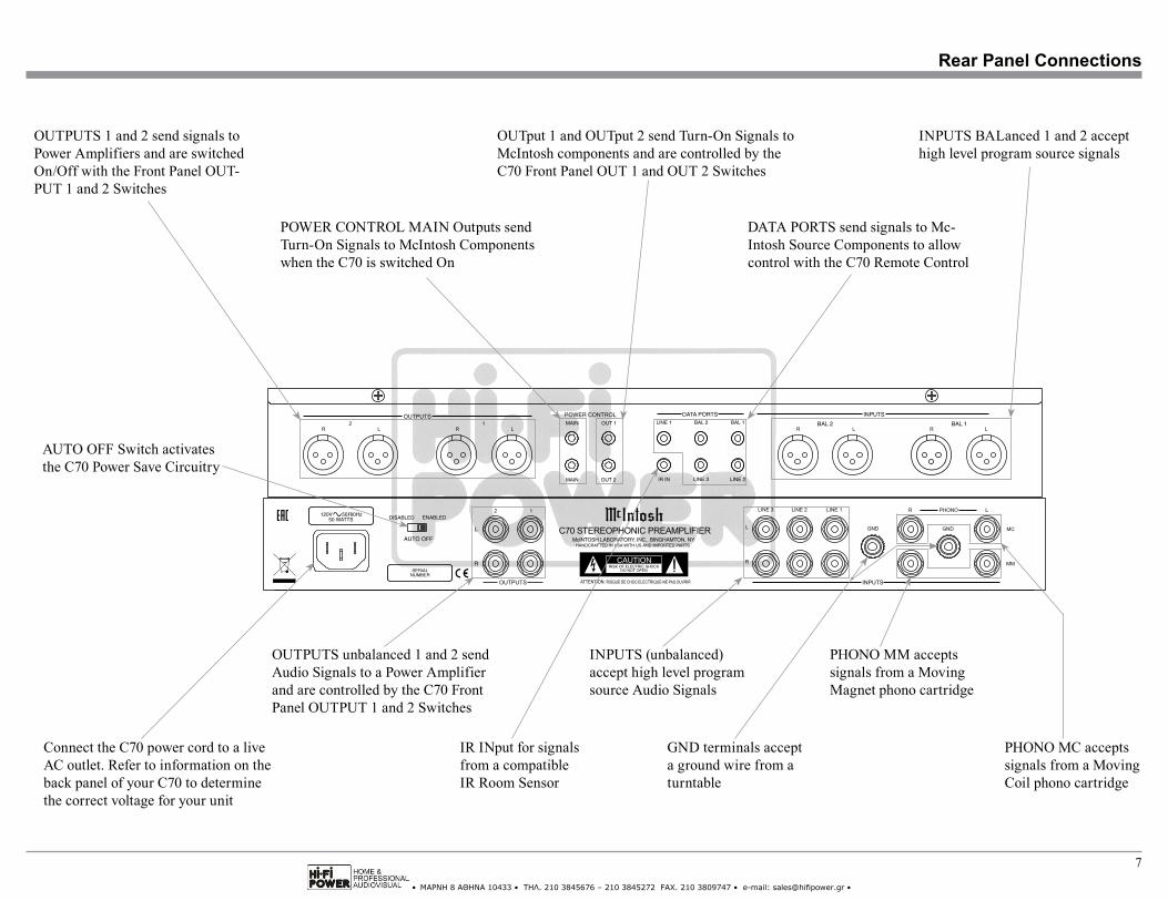
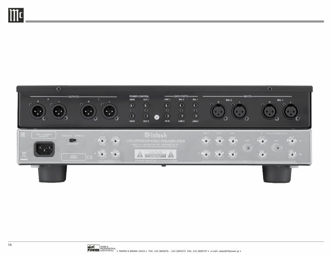
Connect the C70 power cord to a live AC outlet. Refer to information on the back panel of your C70 to determine the correct voltage for your unit
POWER CONTROL MAIN Outputs send Turn-On Signals to McIntosh Components when the C70 is switched On
DATA PORTS send signals to Mc-Intosh Source Components to allow control with the C70 Remote Control
INPUTS BALanced 1 and 2 accept high level program source signals
PHONO MM accepts signals from a Moving Magnet phono cartridge
INPUTS (unbalanced) accept high level program source Audio Signals
OUTPUTS unbalanced 1 and 2 send Audio Signals to a Power Amplifier and are controlled by the C70 Front Panel OUTPUT 1 and 2 Switches
OUTput 1 and OUTput 2 send Turn-On Signals to McIntosh components and are controlled by the C70 Front Panel OUT 1 and OUT 2 Switches
OUTPUTS 1 and 2 send signals to Power Amplifiers and are switched On/Off with the Front Panel OUT-PUT 1 and 2 Switches
PHONO MC accepts signals from a Moving Coil phono cartridge
Rear Panel Connections
AUTO OFF Switch activates the C70 Power Save Circuitry
IR INput for signals from a compatible IR Room Sensor
GND terminals accept a ground wire from a turntable
• ΜΑΡΝΗ 8 ΑΘΗΝΑ 10433 • ΤΗΛ. 210 3845676 – 210 3845272 FAX. 210 3809747 • e-mail: [email protected] •
8
How to Connect the C70
How to Connect the C70The C70 has the ability to automatically switch power On/Off to McIntosh Source Components via the Power Control connections. The Data Port Connec-tions allow for the remote operation of basic functions using the C70 Remote Control.
The connection instructions below, together with the C70 Input and Output Connection Diagrams lo-cated on the separate folded sheet “Mc1A/1B”, are an example of a typical audio system. Your system may vary from this, however the actual components would be connected in a similar manner. For additional in-formation refer to “Connector and Cable Information” on page 3.Power Control Connections:1. Connect a Control Cable from the C70 POWER
CONTROL MAIN (upper) Jack to the Turntable Power Control In Jack.
2. Connect a Control Cable from the Turntable Power Control Out Jack to the Music Server PWR CTRL (Power Control) In Jack.
3. Connect a Control Cable from the Music Server PWR CTRL (Power Control) Out Jack to the SACD/CD Player Power Control Remote In Jack.
4. Connect a Control Cable from the SACD/CD Player Power Control Remote Out Jack to the AM/FM Tuner Control In Jack.
5. Connect a Control Cable from the C70 POWER CONTROL OUT 1 Jack to the Stereo Power Am-plifier (Main Room) Power Control In Jack.
6. Optionally, connect a Control Cable from the Power Amplifier (Main Room) Power Control Out Jack to the Left Channel Loudspeaker Power Control In Jack.
7. Optionally, connect a Control Cable from the Left Channel Loudspeaker Power Control Out Jack to the Right Channel Loudspeaker Power Control In Jack.
8. Connect a Control Cable from the C70 POWERCONTROL OUT 2 Jack to the Stereo Power Am-plifier (Secondary Room) Power Control In Jack.
9. Optionally, connect a Control Cable from thePower Amplifier (Secondary Room) Power ControlOut Jack to the Left Channel Loudspeaker PowerControl In Jack.
10. Optionally, connect a Control Cable from the LeftChannel Loudspeaker Power Control Out Jack tothe Right Channel Loudspeaker Power Control InJack
11. Connect any additional McIntosh Components in asimilar manner, as outlined in steps 1 thru 4.
Data Control Connections:12. Connect a Control Cable from the C70 LINE 1
DATA PORTS Jack to the AM/FM Tuner Data InJack.
13. Connect a Control Cable from the C70 BALance1 DATA PORT Jack to the SACD/CD Player DataIn Jack.
14. Connect a Control Cable from the C70 LINE 2DATA PORT Jack to the Music Streamer Data InJack.
15. Connect any additional McIntosh Components in asimilar manner, as outlined in steps 12 thru 14.
Audio Connections:16. Connect an Audio Cable from the C70 LINE 1
INPUT Jacks to the AM/FM Tuner UNBALancedOutput Connectors.
17. Connect Balanced Cables from the C70 BALanced1 INPUT Jacks to the SACD/CD Player BalancedOutput Connectors.
Note: Unbalanced Audio Cables may be used to con-nect to a C70 Unbalanced Input instead of the Balanced Input.
18. Connect an Audio Cable from the C70 LINE 2INPUT Jacks to the Music Streamer UnbalancedOutput Jacks.
19. Connect the Audio Cables coming from the Turn-table to the C70 MC PHONO L and R INPUTJacks.
Note: If the Turntable has a Moving Magnet Car-tridge, connect the audio cables to the C70 MM PHONO L and R INPUT Jacks instead of the MC Input.
20. Connect any additional McIntosh Components in asimilar manner, as outlined in steps 16 thru 19.
21. Connect Balanced Cables from the C70 OUTPUTS1 L and R Connectors Jacks to the Power Ampli-fier (Main Room) Balanced Input Jacks.
Note: Unbalanced Audio Cables may be used to connect to C70 Unbalanced Output 1 Jacks instead of the Balanced Output Connectors.
22. Optionally, connect Balanced Audio Cables fromthe C70 OUTPUT 2 L and R Connectors to theMcIntosh Power Amplifier (Secondary Room) Bal-anced Input Jacks.
Note: Unbalanced Audio Cables may be used to connect to C70 Unbalanced Output 2 Jacks instead of the Balanced Output Connectors.
Ground Connections:23. Connect the Ground Cable coming from the Turn-
table to the C70 GND Binding Post.AC Power Cords Connections:24. Connect the C70 AC Power Cord to a live AC
outlet as illustrated.
• ΜΑΡΝΗ 8 ΑΘΗΝΑ 10433 • ΤΗΛ. 210 3845676 – 210 3845272 FAX. 210 3809747 • e-mail: [email protected] •
9
• ΜΑΡΝΗ 8 ΑΘΗΝΑ 10433 • ΤΗΛ. 210 3845676 – 210 3845272 FAX. 210 3809747 • e-mail: [email protected] •
10
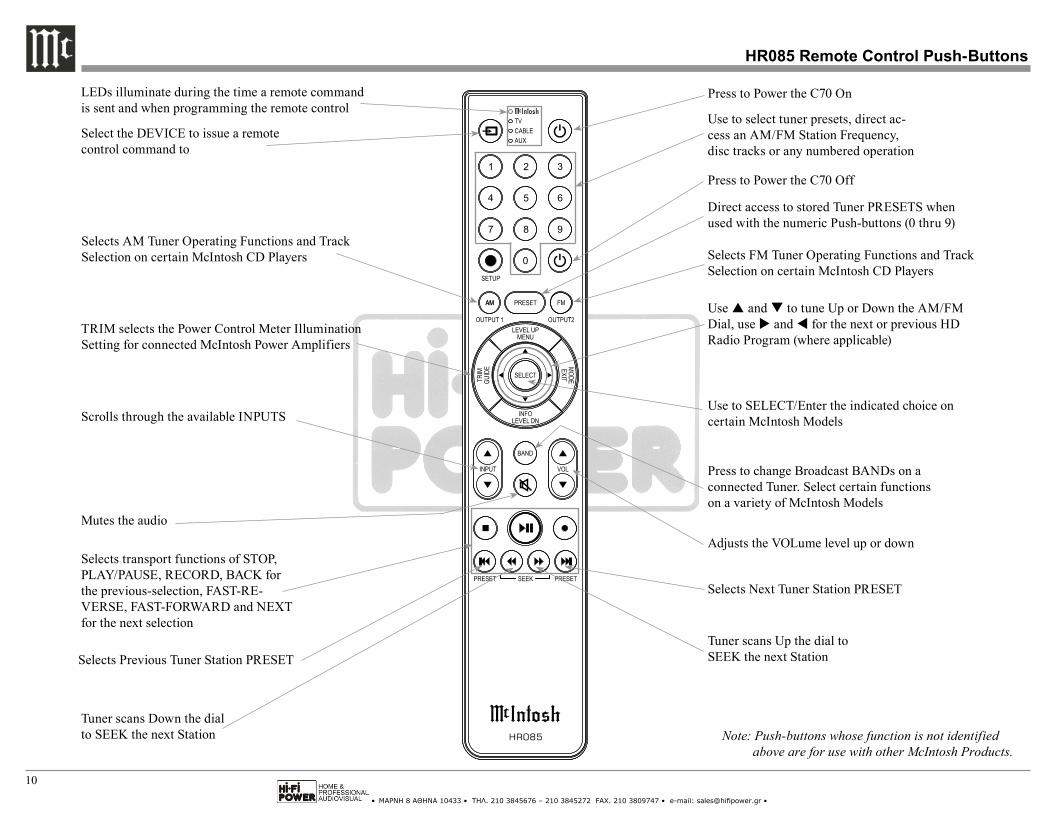
Note: Push-buttons whose function is not identified above are for use with other McIntosh Products.
Press to Power the C70 On
Use to select tuner presets, direct ac-cess an AM/FM Station Frequency, disc tracks or any numbered operation
Mutes the audio
Adjusts the VOLume level up or down
Selects FM Tuner Operating Functions and Track Selection on certain McIntosh CD Players
LEDs illuminate during the time a remote command is sent and when programming the remote control
Press to Power the C70 Off
Scrolls through the available INPUTSUse to SELECT/Enter the indicated choice on certain McIntosh Models
Use p and q to tune Up or Down the AM/FM Dial, use u and t for the next or previous HD Radio Program (where applicable)
Press to change Broadcast BANDs on a connected Tuner. Select certain functions on a variety of McIntosh Models
Select the DEVICE to issue a remote control command to
Direct access to stored Tuner PRESETS when used with the numeric Push-buttons (0 thru 9)
Selects transport functions of STOP, PLAY/PAUSE, RECORD, BACK for the previous-selection, FAST-RE-VERSE, FAST-FORWARD and NEXT for the next selection
Selects Previous Tuner Station PRESET
Tuner scans Down the dial to SEEK the next Station
Selects Next Tuner Station PRESET
Tuner scans Up the dial to SEEK the next Station
HR085 Remote Control Push-Buttons
Selects AM Tuner Operating Functions and Track Selection on certain McIntosh CD Players
TRIM selects the Power Control Meter Illumination Setting for connected McIntosh Power Amplifiers
• ΜΑΡΝΗ 8 ΑΘΗΝΑ 10433 • ΤΗΛ. 210 3845676 – 210 3845272 FAX. 210 3809747 • e-mail: [email protected] •
11
The supplied C70 Remote Control (HR085) is capable of directly controlling the functions of contemporary McIntosh Source Components connected to the C70 via the Data Ports.
Notes: 1. If at any time the C70 seems unresponsive to the HR085 Remote Control Commands, press the DEVICE Push-button to select
first.2. For additional information on using the
HR085 Remote Control with the McIntosh Model, please refer to the “How to Operate” starting on page 13.
Mute SelectionPress the MUTE Push-button on the Remote Control to Mute the Audio in the PREAMP OUT-PUTS (Loudspeakers) and Headphones. The C70 Front Panel Volume Control LED at the 12 O’Clock Position will flash On and Off while the Audio is muted.
Pressing the Mute Push-button a second time or adjusting the Volume Control will un-mute the C70. The LED Illumination of the Volume Control will return to its previous setting.
Trim SelectionThe C70 Default Setting for Meter Illumination of connected McIntosh Power Amplifiers, is ON. If it is desirable to have McIntosh Power Amplifiers’ Meter Illumination switched OFF, press the TRIM (Guide) push-button on the Remote Control after the C70 is passed its warm-up mode.
How to use the HR085 Remote Control
How to use the Remote Control
• ΜΑΡΝΗ 8 ΑΘΗΝΑ 10433 • ΤΗΛ. 210 3845676 – 210 3845272 FAX. 210 3809747 • e-mail: [email protected] •
12
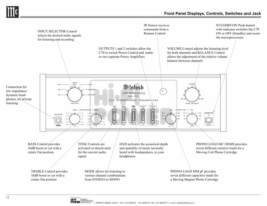
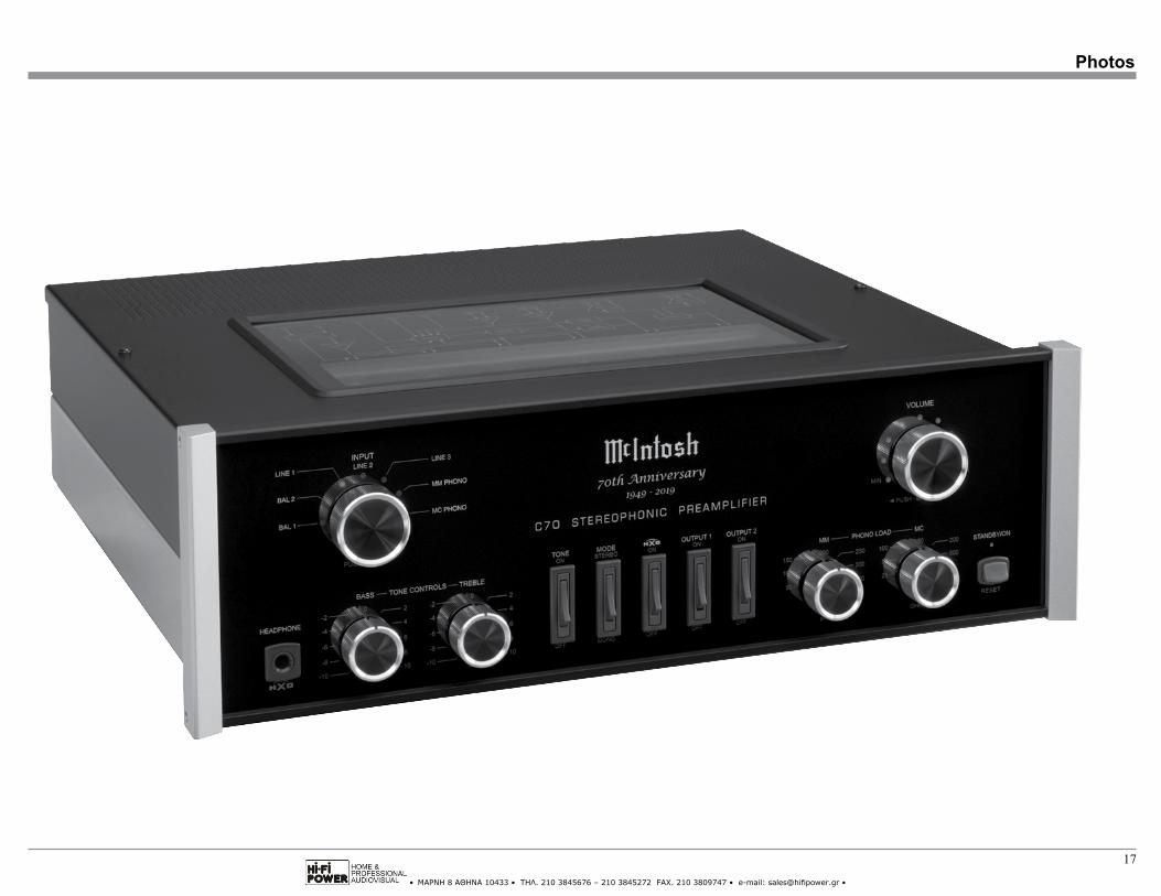
Front Panel Displays, Controls, Switches and Jack
IR Sensor receives commands from a Remote Control
VOLUME Control adjusts the listening level for both channels and BALANCE Control allows the adjustment of the relative volume balance between channels
INPUT SELECTOR Control selects the desired audio signals for listening and recording
TONE Controls areactivated or deactivated for the current audio signal
OUTPUTS 1 and 2 switches allow the C70 to switch Power Control and Audio to two separate Power Amplifiers
MODE allows for listening to various channel combinations from STEREO to MONO
BASS Control provides 10dB boost or cut with a center flat position
TREBLE Control provides 10dB boost or cut with a center flat position
PHONO LOAD MM pF provides seven different capacitive loads for a Moving Magnet Phono Cartridge
PHONO LOAD MC OHMS provides seven different resistive loads for a Moving Coil Phono Cartridge
Connection for low impedance dynamic head-phones, for private listening
HXD activates the acoustical depth and spatiality of music normally heard with loudspeakers, to your headphones
STANDBY/ON Push-button with indicator switches the C70 ON or OFF (Standby) and resets the microprocessors

• ΜΑΡΝΗ 8 ΑΘΗΝΑ 10433 • ΤΗΛ. 210 3845676 – 210 3845272 FAX. 210 3809747 • e-mail: [email protected] •
13
How to Operate
How to Operate
Power On and OffThe Red LED above the STANDBY/ON Push-button lights to indicate the C70 is in Standby mode. Press the STANDBY/ON Push-button on the Front Panel or the (Green) Push-button on the Remote Control. The C70 will go through a TUBE WARMUP (approx-imately 16 seconds) with the Tubes glowing an amber color. The LEDs around the INPUT and VOLUME CONTROLS also become Rotational Active during TUBE WARMUP. The Tubes will then glow green in color and the Input Source and Volume Setting return to the previous settings. Switch the C70 OFF by press-ing the STANDBY/ON Push-button or the (Red) Push-button on the Remote Control.
Note: For an explanation of the Remote Control Push-button functions, refer to pages 10 and 11.
Source SelectionSelect the desired source using the INPUT SELEC-TOR Control on the Front Panel or press the INPUT ▲ or ▼ on the Remote Control. The illuminated LEDs around the control indicate the selected source. Volume ControlRotate the Front Panel VOLUME Control or use the VOLume ▲ (Up) or ▼ (Down) Push-buttons on the Remote Control for the desired listening level. The LEDs surrounding the VOLUME Control indicate the current volume setting between the MINimum and MAXimum setting of LEDs.
Mute ControlPress the INPUT/MUTE Control on the Front Panel to Mute the Audio in the PREAMP OUTPUTS (Loudspeakers) and Headphones. The C70 Front Panel Volume Control LED at the 12 O’Clock Posi-
tion will flash On and Off while the Audio is muted. Pressing the Mute Control a second time or adjusting the Volume Control will un-mute the C70. The LED Illumination of the Volume Control will return to its previous setting.
Balance ControlAdjust the Balance by pressing the VOLUME/BAL-ANCE Control and then immediately rotate the BAL-ANCE Control. The Defaut Setting is equal amplifica-tion for both channels, with illumination of the LED at the center (12 o’clock) position of the Control. Rotate the Control clockwise to increase the Right Channel Volume and reduce the Left Channel Volume. The LEDs on the right side of the BALANCE Control will illuminate as the control is rotated. Rotating the Con-trol counterclockwise will increase the Left Channel Volume and reduce the Right Channel Volume. The LEDs on the left side of the BALANCE Control will illuminate as the control is rotated counterclockwise.
Mode SelectorThe Front Panel MODE SELECTOR Control allows the Left and Right Input Signals from the currently selected source to be combined to outputs sent to the Loudspeakers and Headphones.
Tone SwitchWhen the TONE Switch on the Front Panel is placed in the ON position, the BASS and TREBLE Controls become active. The OFF position of the TONE Switch deactivates the BASS and TREBLE Controls and the Tone Circuitry is totally bypassed for a flat response.
Bass ControlRotate the BASS clockwise to emphasize the low frequency content of the music. Likewise, rotate the BASS counterclockwise to de-emphasize the low frequency content of the music.
Treble ControlRotate the TREBLE clockwise from the center (12 o’clock) position to emphasize the high frequency con-tent of the music. Likewise, rotate the TREBLE coun-terclockwise from the center position to de-emphasize the high frequency content of the music.
Output 1 and 2To switch Off the audio signal going to the Power Amplifiers connected to the C70 Preamplifier Out-puts, place the OUTPUT 1 and/or the OUTPUT 2 Rocker Switch in the OFF Position on the Front Panel. When there is a Power Control Connection between the C70 Power Control OUT 1 or OUT 2 and a Power Amplifier(s), the Power Amplifier(s) will be switched Off.
Phono Load AdjustmentsThere are Phono Load Adjustments for both types of Phono Cartridges, Moving Coil (MC) and Moving Magnet (MM). The resistive load for the MC Input is selectable from 25 ohms to 1,000 ohms. The ca-pacitive load for the MM Input is selectable from 50 picofarads to 350 picofarads.
Select the Phono Load setting using the Front Panel MC or MM Control for the cartridge type connected to the C70. Choose the value closest to the recom-mended load value specified by the Phono Cartridge Manufacturer.
• ΜΑΡΝΗ 8 ΑΘΗΝΑ 10433 • ΤΗΛ. 210 3845676 – 210 3845272 FAX. 210 3809747 • e-mail: [email protected] •
14
Headphones JackConnect a pair of dynamic headphones with a 1/4 inch (6.3mm) stereo phone type plug to the Headphones Jack for private listening.
HXD ModeWhen Headphones are connected to the Front Panel Headphone Jack, place the HXD® switch to the ON position to activate the HXD® Circuitry. To deactivate HXD® place the switch in the OFF position.
Note: HXD® improves the sound localization for Head-phone Listening. HXD® restores the directionality component of the spatial sound stage normally heard with Loudspeaker listening.
Auto Off SwitchThe C70 incorporates an Auto Off Feature, which automatically places the preamplifier into the Power Saving Standby/Off Mode. This occurs approximately 30 minutes after there has been an absence of user ac-tivity (includes changes to any of the Operation Func-tions such as source selection, volume adjustment, etc) or absence of an audio signal. If it is desirable to dis-able the Auto Off Feature, place the Rear Panel AUTO OFF Switch in the DISABLE position.
Reset of MicroprocessorsIn the unlikely event the controls of the C70 stop func-tioning, the microprocessors can be reset by placing the Front Panel STANDBY/ON Switch in the RESET position by holding it in for fifteen seconds and then releasing the switch.
How to Operate, con’t
How to Operate, con’t
• ΜΑΡΝΗ 8 ΑΘΗΝΑ 10433 • ΤΗΛ. 210 3845676 – 210 3845272 FAX. 210 3809747 • e-mail: [email protected] •
15
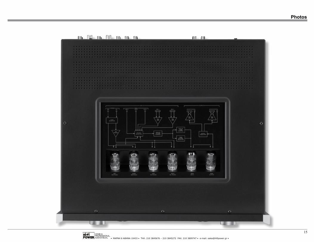
Photos
• ΜΑΡΝΗ 8 ΑΘΗΝΑ 10433 • ΤΗΛ. 210 3845676 – 210 3845272 FAX. 210 3809747 • e-mail: [email protected] •
16
• ΜΑΡΝΗ 8 ΑΘΗΝΑ 10433 • ΤΗΛ. 210 3845676 – 210 3845272 FAX. 210 3809747 • e-mail: [email protected] •
17
Photos
• ΜΑΡΝΗ 8 ΑΘΗΝΑ 10433 • ΤΗΛ. 210 3845676 – 210 3845272 FAX. 210 3809747 • e-mail: [email protected] •
18
Specifications
Specifications
Frequency Response+0, -0.5dB from 20Hz to 20,000Hz+0, -3dB from 15Hz to 100,000Hz
Total Harmonic Distortion0.08% from 20Hz to 20,000Hz
Rated Output (Output 1 and 2)2.5V Unbalanced, 5V Balanced
Maximum Voltage Output8V RMS Unbalanced, 16V RMS Balanced
Sensitivity (for rated output)High Level, 450mV Unbalanced, 900mV BalancedPhono MM, 4.5mVPhono MC, 0.45mV
Signal To Noise Ratio (A-Weighted)High Level - 100dB (Below rated output)MM Phono - 75dB (Below 5mV input)MC Phono - 75dB (Below 0.5mV input)
Input ImpedanceHigh Level - 22K ohms Unbalanced 44k ohms BalancedPhono MM, 50pF, 100pF, 150pF, 200pF, 250pF, 300pF or 350pF; 47K ohmsPhono MC, 25, 50, 100, 150, 200, 500 or 1,000 ohms; 100pF
Maximum Input SignalHigh Level, 5V Unbalanced, 10V BalancedPhono MM, 50mVPhono MC, 5mV
Tone ControlsBass Control ± 10dB @20HzTreble Control ± 10dB @20,000Hz
Voltage GainHigh Level to Output 1 and 2: 15dBPhono MM to Output 1 and 2: 40dBPhono MC to Output 1 and 2: 60dB
Output Impedance100 ohms Unbalanced200 ohms Balanced
Headphone Load Impedance16 ohms to 250 ohms
Power Control Output12VDC, 25mA
Tube Compliment6 Tubes, Five - 12AX7A and One - 12AT7 (viewed thru the Top Cover Window)
Power RequirementsField AC Voltage conversion of the C70 is not pos-sible. The C70 is factory configured for one of the following AC Voltages:100V ~ 50/60Hz at 50 watts110V ~ 50/60Hz at 50 watts120V ~ 50/60Hz at 50 watts127V ~ 50/60Hz at 50 watts220V ~ 50/60Hz at 50 watts230V ~ 50/60Hz at 50 watts240V ~ 50/60Hz at 50 wattsStandby, less than 0.5 watts
Note: Refer to the rear panel of the C70 for the correct voltage.
Overall DimensionsWidth is 17-1/2 inches (44.45cm)Height is 6 inches (15.24cm) including feetDepth is 18 inches (45.72cm) including the Front Panel, Knobs and Cables
Weight25 pounds (11.3 kg) net, 41.4 pounds (18.8 kg) in ship-ping carton
Shipping Carton DimensionsWidth is 26-1/2 inches (67.3cm)Depth is 24-1/4 inches (61.6cm)Height is 11-3/4 inches (29.9cm)
• ΜΑΡΝΗ 8 ΑΘΗΝΑ 10433 • ΤΗΛ. 210 3845676 – 210 3845272 FAX. 210 3809747 • e-mail: [email protected] •
19
Packing Instructions
Packing Instructions
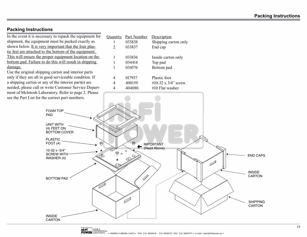
Quantity Part Number Description 1 033838 Shipping carton only 2 033837 End cap
1 033836 Inside carton only 1 034414 Top pad 1 034576 Bottom pad
4 017937 Plastic foot 4 400159 #10-32 x 3/4” screw 4 404080 #10 Flat washer
In the event it is necessary to repack the equipment for shipment, the equipment must be packed exactly as shown below. It is very important that the four plas-tic feet are attached to the bottom of the equipment. This will ensure the proper equipment location on the bottom pad. Failure to do this will result in shipping damage.Use the original shipping carton and interior parts only if they are all in good serviceable condition. If a shipping carton or any of the interior part(s) are needed, please call or write Customer Service Depart-ment of McIntosh Laboratory. Refer to page 2. Please see the Part List for the correct part numbers.
FOAM TOPPAD

• ΜΑΡΝΗ 8 ΑΘΗΝΑ 10433 • ΤΗΛ. 210 3845676 – 210 3845272 FAX. 210 3809747 • e-mail: [email protected] •
The continuous improvement of its products is the policy of McIntosh Laboratory Incorporated who reserve the right to improve design without notice.Printed in the U.S.A.
McIntosh Laboratory, Inc.2 Chambers Street
Binghamton, NY 13903www.mcintoshlabs.com
McIntosh Part No. 04191300