Mathematical Model of Non-Coherent-DLL Discriminator ...BOC is a square waveform subcarrier...
15
Positioning, 2013, 4, 65-79 http://dx.doi.org/10.4236/pos.2013.41008 Published Online February 2013 (http://www.scirp.org/journal/pos) 65 Mathematical Model of Non-Coherent-DLL Discriminator Output and Multipath Envelope Error for BOC (α, β) Modulated Signals Khaled Rouabah 1 , Chebir Saifeddine 1 , Salim Atia 1 , Mustapha Flissi 1 , Djamel Chikouche 2 1 Electronics Department, LMSE Laboratory, University of Mohamed El-Bachir El-Ibrahimi, Bordj Bou Arréridj, Algeria; 2 Electronis Department, LIS Laboratory, University of M’sila, M’sila, Algeria. Email: [email protected] Received November 19 th , 2012; revised December 20 th , 2012; accepted December 29 th , 2012 ABSTRACT In this paper we propose the derivation of the expressions for the non-coherent Delay Locked Loop (DLL) Discrimina- tor Curve (DC) in the absence and presence of Multipath (MP). Also derived, are the expressions of MP tracking errors in non-coherent configuration. The proposed models are valid for all Binary Offset Carrier (BOC) modulated signals in Global Navigation Satellite Systems (GNSS) such as Global Positioning System (GPS) and Future Galileo. The non- coherent configuration is used whenever the phase of the received signal cannot be estimated and thus cannot be de- modulated. Therefore, the signal must be treated in a transposed band by the non-coherent DLL. The computer imple- mentations show that the proposed models coincide with the numerical ones. Keywords: BOC Modulation; GNSS; PRN Code; Multipath; Discriminator; Envelope Error 1. Introduction This template, MP propagation is widely recognized as the main error source in GNSS systems. In fact, the presence of MP signals provokes tracking error in the DLL which is a code discriminator that utilizes Early- minus-late correlators [1], and thus it causes ranging er- rors in positioning the receiver. The MP tracking perfor- mances depend on various signal and receiver parameters [2,3] like signal type of modulation scheme such as BOC [3] and Multiplexed BOC (MBOC) [4,5] modulations for Galileo signals and modernized GPS signals [6] and Bi- nary Phase Shift Keying (BPSK) for GPS signals [6], pre-correlation bandwidth and filter characteristics [7], type of Pseudo Random Noise (PRN) code, relative am- plitude of MP signal, number of MP signals, MP delay, chip spacing between correlators in the DLL loop, type of discriminator used for tracking [8]. The influence of MP as an error source has resulted in the development of different MP mitigation techniques. These techniques are typically categorized in terms of antenna design [9,10], improved discriminator architecture, and post-processing of discernible objects [11-13]. In discriminator-archi- tecture design, various techniques are proposed in the literature. Performances of the classical techniques are compared in [14] under the assumption that only single MP exists. In reference [15] the authors have proposed the “Virtual MP based Technique” for short delay MP mitigation. This technique is valid in some cases and it is limited in other cases [16]. In reference [17,18], an analysis and design of discriminator code tracking algo- rithms has been done to prove that the Narrow Correlator (NC) [19] is still the optimum choice among the consid- ered algorithms. On the other hand, various approaches are also proposed to estimate the parameters of MP sig- nals such as delays, amplitudes and phases. The esti- mated MP signals are then eliminated to track only the Line of Sight (LOS) signal [20-26]. All these techniques have proved to have the optimal performances in MP environments. However, all of them require a lot of hardware resources. In addition to the MP effect, another limitation exists in BOC and MBOC modulated signals due to the presence of side peaks in Correlation Function (CF) and thus the presence of several passages by zero in the DLL-DC which complicates the operation of the tracking process. For this reason various techniques are proposed for side peaks’ cancelation. The most basic of them are built on the basis of the CF of BOC and MBOC signals [27-30]. Other techniques, based on the modifica- tion of the locally generated codes, are proposed in [31-34]. The majority of these methods are based on computational geometry of CF and DC which require the knowledge of the mathematical models of CF and DCs [35]. Several models Have been proposed in scientific Copyright © 2013 SciRes. POS
Transcript of Mathematical Model of Non-Coherent-DLL Discriminator ...BOC is a square waveform subcarrier...
Positioning, 2013, 4, 65-79 http://dx.doi.org/10.4236/pos.2013.41008 Published Online February 2013 (http://www.scirp.org/journal/pos)
65
Mathematical Model of Non-Coherent-DLL Discriminator Output and Multipath Envelope Error for BOC (α, β) Modulated Signals
Khaled Rouabah1, Chebir Saifeddine1, Salim Atia1, Mustapha Flissi1, Djamel Chikouche2
1Electronics Department, LMSE Laboratory, University of Mohamed El-Bachir El-Ibrahimi, Bordj Bou Arréridj, Algeria; 2Electronis Department, LIS Laboratory, University of M’sila, M’sila, Algeria. Email: [email protected] Received November 19th, 2012; revised December 20th, 2012; accepted December 29th, 2012
ABSTRACT
In this paper we propose the derivation of the expressions for the non-coherent Delay Locked Loop (DLL) Discrimina-tor Curve (DC) in the absence and presence of Multipath (MP). Also derived, are the expressions of MP tracking errors in non-coherent configuration. The proposed models are valid for all Binary Offset Carrier (BOC) modulated signals in Global Navigation Satellite Systems (GNSS) such as Global Positioning System (GPS) and Future Galileo. The non- coherent configuration is used whenever the phase of the received signal cannot be estimated and thus cannot be de-modulated. Therefore, the signal must be treated in a transposed band by the non-coherent DLL. The computer imple-mentations show that the proposed models coincide with the numerical ones. Keywords: BOC Modulation; GNSS; PRN Code; Multipath; Discriminator; Envelope Error
1. Introduction
This template, MP propagation is widely recognized as the main error source in GNSS systems. In fact, the presence of MP signals provokes tracking error in the DLL which is a code discriminator that utilizes Early- minus-late correlators [1], and thus it causes ranging er- rors in positioning the receiver. The MP tracking perfor- mances depend on various signal and receiver parameters [2,3] like signal type of modulation scheme such as BOC [3] and Multiplexed BOC (MBOC) [4,5] modulations for Galileo signals and modernized GPS signals [6] and Bi- nary Phase Shift Keying (BPSK) for GPS signals [6], pre-correlation bandwidth and filter characteristics [7], type of Pseudo Random Noise (PRN) code, relative am- plitude of MP signal, number of MP signals, MP delay, chip spacing between correlators in the DLL loop, type of discriminator used for tracking [8]. The influence of MP as an error source has resulted in the development of different MP mitigation techniques. These techniques are typically categorized in terms of antenna design [9,10], improved discriminator architecture, and post-processing of discernible objects [11-13]. In discriminator-archi- tecture design, various techniques are proposed in the literature. Performances of the classical techniques are compared in [14] under the assumption that only single MP exists. In reference [15] the authors have proposed
the “Virtual MP based Technique” for short delay MP mitigation. This technique is valid in some cases and it is limited in other cases [16]. In reference [17,18], an analysis and design of discriminator code tracking algo-rithms has been done to prove that the Narrow Correlator (NC) [19] is still the optimum choice among the consid- ered algorithms. On the other hand, various approaches are also proposed to estimate the parameters of MP sig- nals such as delays, amplitudes and phases. The esti- mated MP signals are then eliminated to track only the Line of Sight (LOS) signal [20-26]. All these techniques have proved to have the optimal performances in MP environments. However, all of them require a lot of hardware resources. In addition to the MP effect, another limitation exists in BOC and MBOC modulated signals due to the presence of side peaks in Correlation Function (CF) and thus the presence of several passages by zero in the DLL-DC which complicates the operation of the tracking process. For this reason various techniques are proposed for side peaks’ cancelation. The most basic of them are built on the basis of the CF of BOC and MBOC signals [27-30]. Other techniques, based on the modifica- tion of the locally generated codes, are proposed in [31-34]. The majority of these methods are based on computational geometry of CF and DC which require the knowledge of the mathematical models of CF and DCs [35]. Several models Have been proposed in scientific
Copyright © 2013 SciRes. POS
Mathematical Model of Non-Coherent-DLL Discriminator Output and Multipath Envelope Error for BOC (α, β) Modulated Signals
66
literature. Indeed, the CF of BOC (α, α), which is func- tion of a specified width, has been proposed in reference [36]. In reference [37] authors have proposed another model characterizing the CF for case BOC (pα, α) (p in- teger). The general model BOC (α, β) have been pro- posed in reference [38]. In the same reference, the au- thors have proposed two other models which characterize respectively coherent DC and coherent MP tracking error. However, these models are valid only for some catego- ries of BOC (α, β) modulated signals. In addition, the latter models contain some typing errors that have been corrected in [39].
In the coherent code tracking process the operation of estimating the delay of the received signal is function of the phase estimated by the Phase Locked Loop (PLL). Indeed, if the carrier phase of the received signal is esti-mated, the code delay search is called coherent signal tracking. In contrast, if the carrier phase is ignored, the search is called non-coherent signal tracking. This later process is used in the majority of the receiver’s architec- tures. Hence, this paper is devoted to the modeling of the non-coherent DLL-DC and MP tracking errors of BOC (α, β) codes. The paper is organized as follows:
We present firstly the coherent DLL-DC and we de- rive the proposed non-coherent one. Secondly, we derive the proposed non-coherent MP tracking error model. Finally we end up by a comparison of the proposed mod- els and the numerical ones based on computer imple-mentations.
2. Coherent DLL-DC and the Proposed Non-Coherent
In the GNSS system the computation of the delay of the
received signal is realized by the peak location of the CF, noted R , between the received signal _R BOCS t
t
t
and the locally generated signal . This CF is given by the following equation:
_L BOCS
_ _ dR BOC L BOCR S t S t
(1)
with: is the time shift applied to the locally generated code.
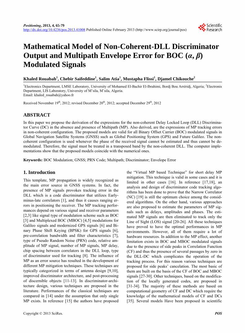
BOC is a square waveform subcarrier modulation, where a signal s t (the signal which is going to be modulated) is multiplied by a square waveform subcar-rier of frequency sf . Formally, the BOC-modulated signal BOCs t can be written as [3]:
BOC sign sin 2π s s t s t f t (2)
For GNSS signals, the notation BOC (α, β) is used, where α and β are two indices satisfying the relationships
MHz 1.023 MHzsf and
MHz 1.023 MHzXf
where: fX is PRN code chipping rate. BOC (α, α) modulation generalizes one zero crossing
on spreading code chip. The number of zero crossing in one chip of the PRN code is proportional to both sub- carrier frequency and chipping rate code. An example showing the BOC-modulated waveform is shown in Figure 1 for BOC (α, α) modulation.
As shown in this figure, the wave-form of the sub- carrier, the spreading code and the resulting modulated BOC signal are plotted.
The mathematical model of the normalized CF of
Figure 1. BOC (α, α) modulation.
Copyright © 2013 SciRes. POS
Mathematical Model of Non-Coherent-DLL Discriminator Output and Multipath Envelope Error for BOC (α, β) Modulated Signals
67
these BOC modulated signals has been proposed in ref-erence [37] and it is given as follows
1 2 1 1 21
for
0,
otherwhise
n
sc
X X
R
n M n n M n
M M
T T
,T
(3)
where M is a constant defined by twice the ratio between the two parameters, α and β and it is given as:
2M
(4)
1sc
s
Tf
, is the minimum time associated with a con-
stant value of the subcarrier
sc
nT
(5)
with represents the ceiling operator and 1
XX
Tf
,
is the chip spacing of the PRN code used in GNSS sig- nals, given by the ratio between Coarse Acquisition C A GPS code chip spacing C AT and the parame-
ter C AX
TT
.
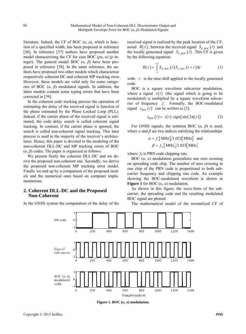
The peak location of the CF can be accomplished by determining the position of the zero-crossing of the DC. Here, Early-minus-late correlators are necessary to de-termine the location of this zero-crossing. The early and late CFs in the traditional DLL scheme together with the DC for BOC (α, α) code, in coherent configuration, are shown in Figure 2. In the absence of MP and noise, the DC of the DLL is given by the following equation:
Late EarlycD R R (6)
where: early 2R R
and late 2
R R
are re-
spectively the late and early CFs. R is the CF between the received and the locally gen-
erated signals. ∆ is the Early-minus-late spacing. As this DC is function of the Early-minus-late spacing,
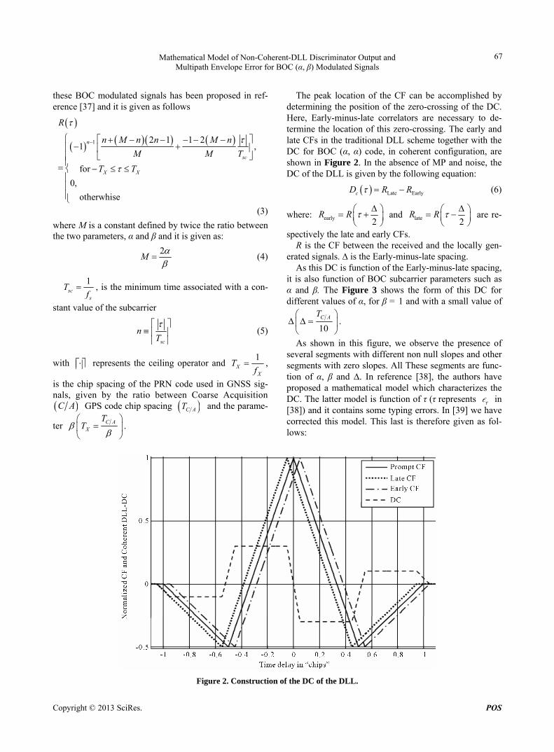
it is also function of BOC subcarrier parameters such as α and β. The Figure 3 shows the form of this DC for different values of α, for β = 1 and with a small value of
10C AT
.
As shown in this figure, we observe the presence of several segments with different non null slopes and other segments with zero slopes. All These segments are func-tion of α, β and ∆. In reference [38], the authors have proposed a mathematical model which characterizes the DC. The latter model is function of τ (τ represents in [38]) and it contains some typing errors. In [39] we have corrected this model. This last is therefore given as fol-lows:
Figure 2. Construction of the DC of the DLL.
Copyright © 2013 SciRes. POS
Mathematical Model of Non-Coherent-DLL Discriminator Output and Multipath Envelope Error for BOC (α, β) Modulated Signals
68
Figure 3. Normalized coherent DC for different values of α and β.
1
1
2 8,
for 02
for 12 2
12
for 1 12 2
12
for2 2
0
for2
for 0
C A
i
sc sc
i i sc
C sc
M
M XC A
X X
X
T
D
i T iT
D D i T
D i T
D TT
T T
T
D
sci T
(7)
with:
2 , 1, ,sc
i iT
M (8)
1
2 8
C A
DT
(9)
1 2D D1
(10)
11 4 1 8 , 2, ,
i
iC A
D i iT
M (11)
2 1 21 , 2, ,
i
iC A
M iD i
M T
M (12)
In the non-coherent configuration, the normalized DC is given as follows [40]:
2 2early late
2 2
2 2
ncD R R
R R
(13)
The squared normalized CF can be given from Equa-tion (3) as follows:
2
2
,2 1 1 2
for
0,
otherwhise
sc
X X
n M n n M n
M MR T T
T
(14)
The Equation (13) can be simplified as follows:
2 2 2
ncD
R R R R
2
(15)
The non-coherent DC is function of the coherent one. Thus this equation can be simplified as follows:
Copyright © 2013 SciRes. POS
Mathematical Model of Non-Coherent-DLL Discriminator Output and Multipath Envelope Error for BOC (α, β) Modulated Signals
69
2 2nc cD D R R
(16)
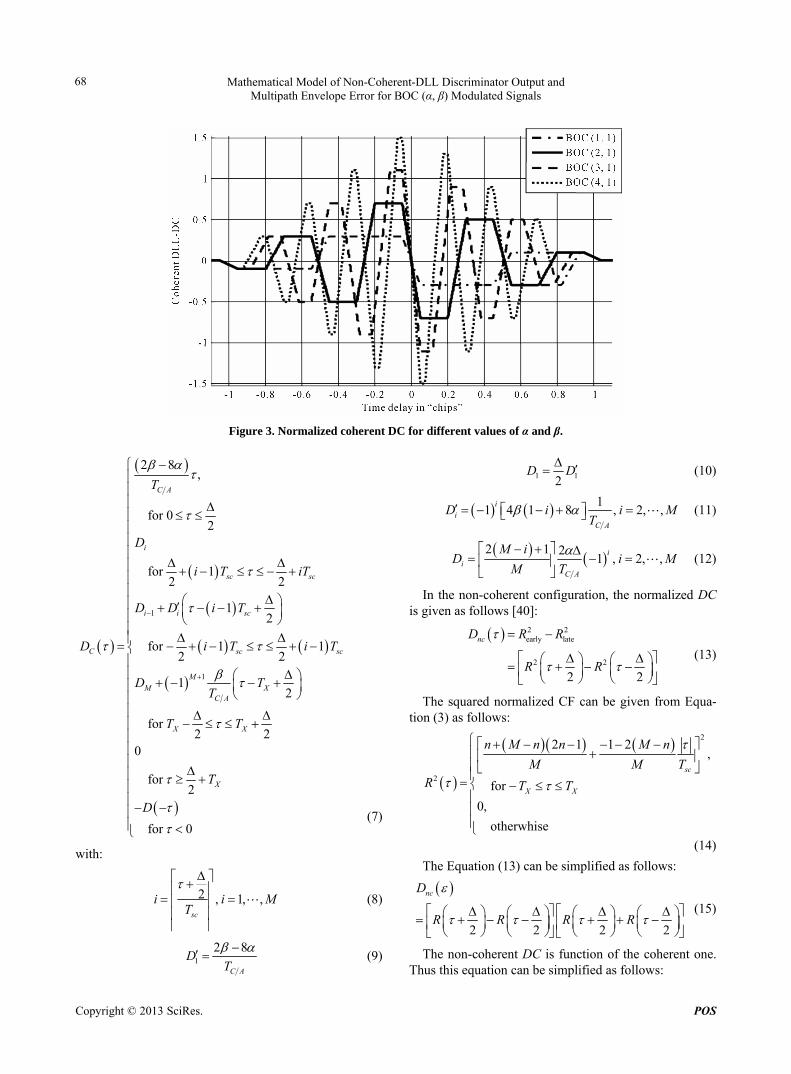
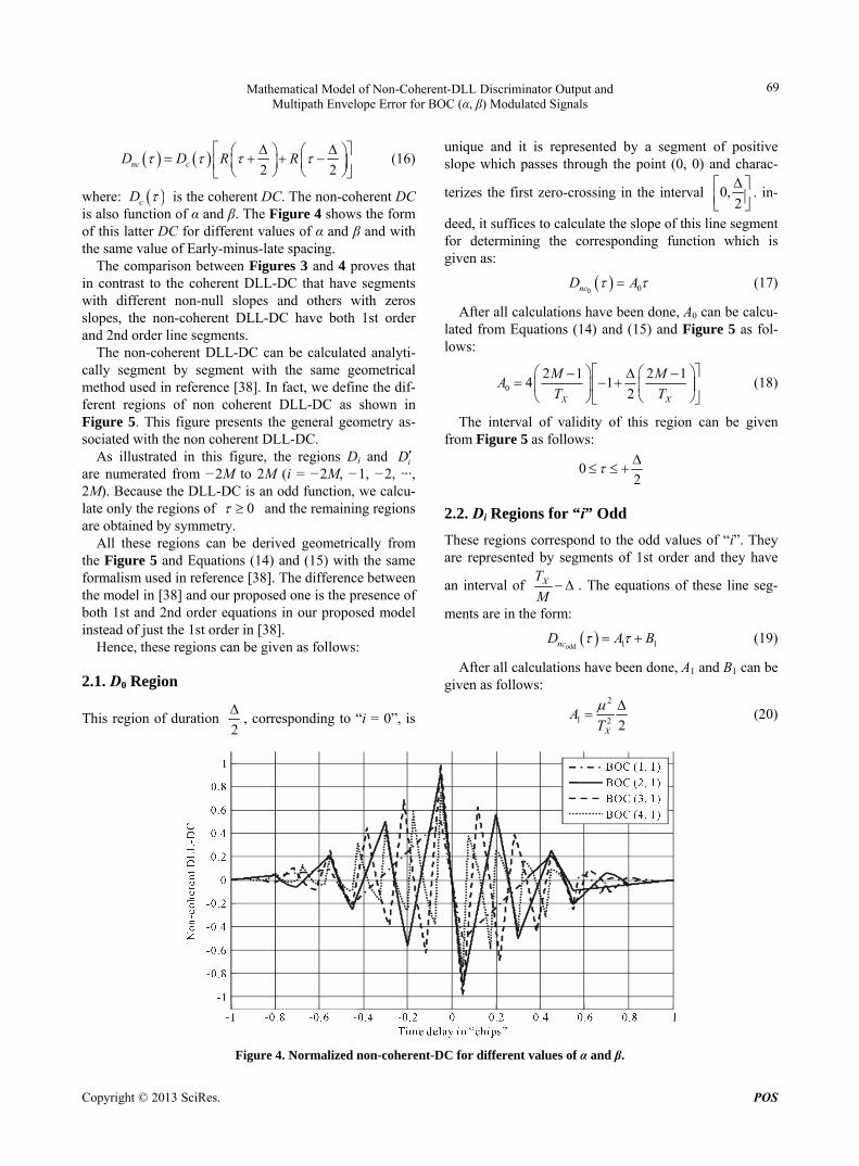
where: cD is the coherent DC. The non-coherent DC is also function of α and β. The Figure 4 shows the form of this latter DC for different values of α and β and with the same value of Early-minus-late spacing.
The comparison between Figures 3 and 4 proves that in contrast to the coherent DLL-DC that have segments with different non-null slopes and others with zeros slopes, the non-coherent DLL-DC have both 1st order and 2nd order line segments.
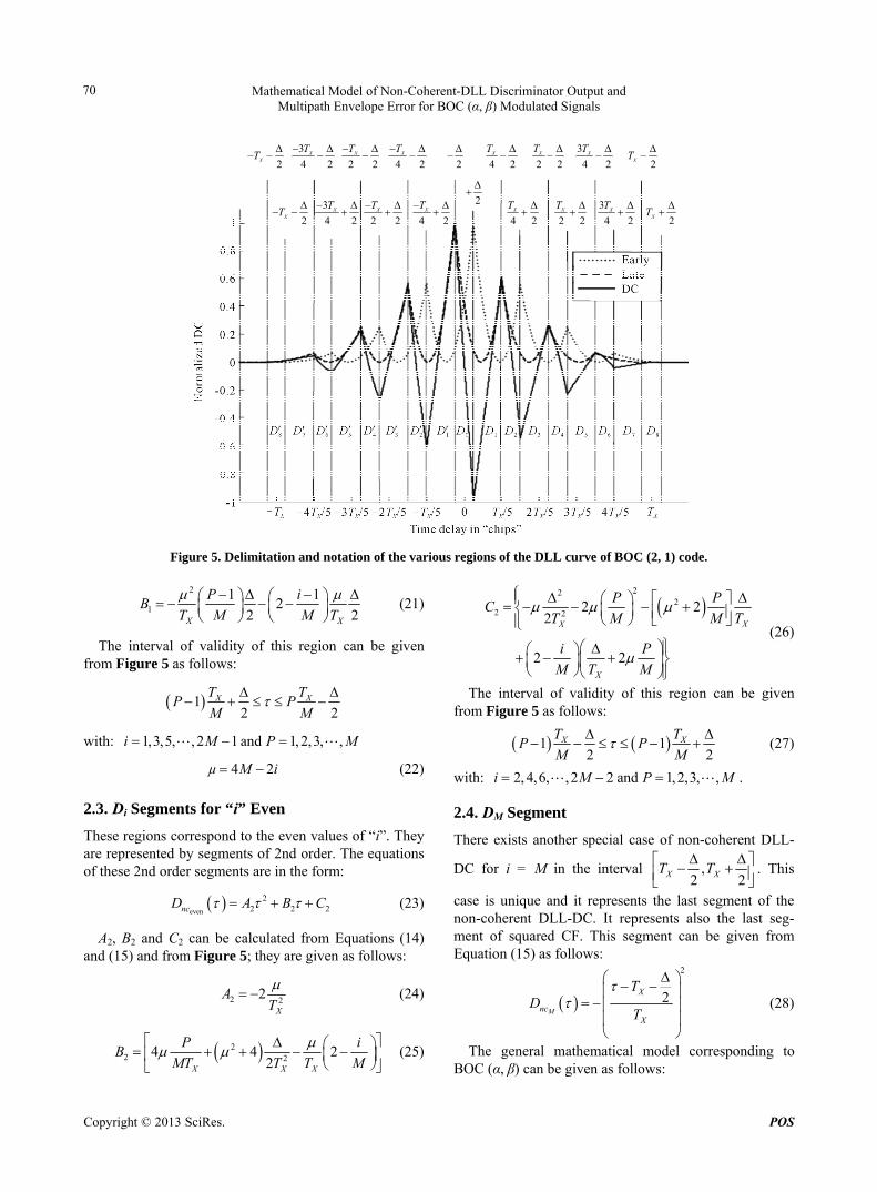
The non-coherent DLL-DC can be calculated analyti-cally segment by segment with the same geometrical method used in reference [38]. In fact, we define the dif-ferent regions of non coherent DLL-DC as shown in Figure 5. This figure presents the general geometry as-sociated with the non coherent DLL-DC.
As illustrated in this figure, the regions Di and iD are numerated from −2M to 2M (i = −2M, −1, −2, ···, 2M). Because the DLL-DC is an odd function, we calcu-late only the regions of 0 and the remaining regions are obtained by symmetry.
All these regions can be derived geometrically from the Figure 5 and Equations (14) and (15) with the same formalism used in reference [38]. The difference between the model in [38] and our proposed one is the presence of both 1st and 2nd order equations in our proposed model instead of just the 1st order in [38].
Hence, these regions can be given as follows:
2.1. D0 Region
This region of duration 2
, corresponding to “i = 0”, is
unique and it is represented by a segment of positive slope which passes through the point (0, 0) and charac-
terizes the first zero-crossing in the interval 0,2
. in-
deed, it suffices to calculate the slope of this line segment for determining the corresponding function which is given as:
0 0ncD A (17)
After all calculations have been done, A0 can be calcu-lated from Equations (14) and (15) and Figure 5 as fol-lows:
0
2 1 2 14 1
2X X
M MA
T T
(18)
The interval of validity of this region can be given from Figure 5 as follows:
02
2.2. Di Regions for “i” Odd
These regions correspond to the odd values of “i”. They are represented by segments of 1st order and they have
an interval of XT
M . The equations of these line seg-
ments are in the form:
odd 1ncD A 1B (19)
After all calculations have been done, A1 and B1 can be given as follows:
2
1 2 2X
AT
(20)
Figure 4. Normalized non-coherent-DC for different values of α and β.
Copyright © 2013 SciRes. POS
Mathematical Model of Non-Coherent-DLL Discriminator Output and Multipath Envelope Error for BOC (α, β) Modulated Signals
70
2XT
3
4 2XT
2 2XT
4 2XT
2
4 2XT
2 2XT
3
4 2XT
2XT
2XT
3
4 2XT
2 2XT
4 2XT
2
4 2XT
2 2XT
3
4 2XT
2XT
Figure 5. Delimitation and notation of the various regions of the DLL curve of BOC (2, 1) code.
2
1
1 12
2 2X X
P iB
T M M T
(21)
The interval of validity of this region can be given from Figure 5 as follows:
12 2
X XT TP P
M M
with: 1,3,5, , 2 1 and 1, 2,3, ,i M P M
4 2µ M i (22)
2.3. Di Segments for “i” Even
These regions correspond to the even values of “i”. They are represented by segments of 2nd order. The equations of these 2nd order segments are in the form:
even
22 2ncD A B 2C (23)
A2, B2 and C2 can be calculated from Equations (14) and (15) and from Figure 5; they are given as follows:
2 22X
AT
(24)
22 24 4 2
2X XX
PB
MT T MT
22
22 2
2 22
2 2
XX
X
P PC
M M TT
i P
M T M
(26)
The interval of validity of this region can be given from Figure 5 as follows:
1 12 2
XTP P XT
M M
(27)
with: 2, 4,6, , 2 2 and 1,2,3, ,i M P M .
2.4. DM Segment
There exists another special case of non-coherent DLL-
DC for i = M in the interval ,2 2X XT T
. This
case is unique and it represents the last segment of the non-coherent DLL-DC. It represents also the last seg-ment of squared CF. This segment can be given from Equation (15) as follows:
i
(25)
2
2M
X
ncX
TD
T
(28)
The general mathematical model corresponding to BOC (α, β) can be given as follows:
Copyright © 2013 SciRes. POS
Mathematical Model of Non-Coherent-DLL Discriminator Output and Multipath Envelope Error for BOC (α, β) Modulated Signals
71
2
222 2
2 2
2
2
for2 2
–1 12
2
for 12 2
4sign 2 4 2 2
2 2
4 22
X
X
X X
X X
X X
ncX XX X
X
T
T
T T
P iµ
T T M M
T TP P
M M
P i
M T MD
T MT T
P
M T
P
for 1 12 2
2 1 2 14 1
2
for2
X
X X
X X
i P
M T M
T TP P
M M
M M
T T
(29)
with:
2
sc
iT
(30)
1, 2,3, ,i M and . 1, 2,3, ,P M
3. Proposed Non-Coherent MP Tracking Error
MP propagation represents an important error source in GNSS positioning. This error is due to the fact that the signal reaches the receiver antenna by two or more paths. In urban environment the causes of MP include reflection from objects such as buildings. In presence of both LOS and one specular reflected signals, the baseband signal model is defined as follows [3]:
0 10 0 1 1e ej j
rS t a p t a p t n t (31)
with:
0 : Delay of Line Of Sight (LOS) signal;
1 : Delay of MP signal;
0
aa : LOS signal amplitude;
1 : MP signal amplitude;
0 : Phase of LOS signal;
1 : Phase shift due to the MP signal;
n t : Additive White Gaussian Noise (AWGN); p t : PN code plus subcarrier.
Consequently, the receiver tries to correlate with all components of the received signal. Analytically, the LOS and MP signal may be treated separately. Thus, one may consider the CF associated with LOS (LOSCF) and the CF associated with MP signal (MCF). At any point, these two functions can be vector summed to yield the CF as-sociated with the composite signal (CCF).
The normalized CF (with respect to 0, a 0 and 0 ) of the composite signal can be given as [20]:
1 1 cosCCFR R a R 1 (32)
with: R : Ideal CF. The CF of the received signal is distorted as shown in
Figure 6 for BOC (α, α) code (Solid line). Consequently, the distorted DLL-DC has a zero-
crossing at non-zero code tracking error. As shown in Figure 7, this distortion ensues in a shift
between the received signal and the locally generated code provoking an error in the tracking process. In what follows we propose a general model of MP tracking er-rors of non-coherent DLL DC.
In the presence of MP signal the coherent DLL-DC is given as follows:
Copyright © 2013 SciRes. POS

Mathematical Model of Non-Coherent-DLL Discriminator Output and Multipath Envelope Error for BOC (α, β) Modulated Signals
72
Figure 6. LOSCF, MCF and CCF of the BOC (α, α) code.
Figure 7. Non-coherent DLL-DC in the presence of MP.
_ 2 2C CCF CCF CCFD R R
(33)
_
1
1
2 2
2 2
2 2
2 2
C CCFD R AR
R AR
R R
A R R
1
1
(34)
Finally Equation (1) becomes:
_ 1C CCF C CD D AD (35)
where CD is the ideal coherent DLL-DC and:
1 1cosA a (36)
In the presence of MP signal the non-coherent DLL- DC can be given as:
2 2
_
2
1
2
1
2 2
2 2
2 2
NC CCF CCF CCFD R R
R AR
R AR
(37)
Equation (37) becomes:
_
2 2
2 2 21 1
1
1
2 2
2 2
22 2
2 2
NC CCFD
R R
A R R
A R R
R R
(38)
2_ 1 ErrNC CCF nc ncD D A D (39)
where: Err is an error term given as:
1
1
Err 22 2
2 2
A R R
R R
(40)
In contrast to the coherent discriminator that contains two terms characterizing respectively the LOS and the MP DCs (Equation (35)), the non-coherent DLL dis-criminator contains three terms (Equation (39)). In fact, the first term characterizes the non-coherent LOS DC, the second one characterizes the non-coherent MP DC and finally the third one characterizes the influence of the LOS on the MP and vice versa. To compute the non- coherent MP tracking error, we have to resolve the Equa-tion (39) according to 1 . The direct resolution of this equation presents a certain difficulty in comparison to the coherent configuration. In fact, a simplified form of this equation can be given as follows:
Copyright © 2013 SciRes. POS
Mathematical Model of Non-Coherent-DLL Discriminator Output and Multipath Envelope Error for BOC (α, β) Modulated Signals
Copyright © 2013 SciRes. POS
73
1
1
1
2 2
2 2
2 2
2 2
2 2
2
CCFNC CCF CCF
CCF CCF
D R R
R R
R AR
R AR
R AR
R
12AR
(41)
According to this equation, we can conclude that the non-coherent DLL is function of the coherent one. In fact, the zero crossing of the non-coherent DLL is the same as that of the coherent one. This is because in the term of error, in Equation (40), which is clearly the sum of four CFs (Early-minus-late LOS CFs and Early-minus-late MP CFs), each Early-minus-late couple consists of two overlapping CFs whose sum is constant and non null in
the linear zone ,2 2
of the DC. This is explained
by the equal but reversed slopes of their line segments in this interval. This constant is given as follows:
1 22
sc
MI
MT
for
2 2
(45)
_
1
2 2
2 2
C CCFD R AR
R AR
1
I
(42)
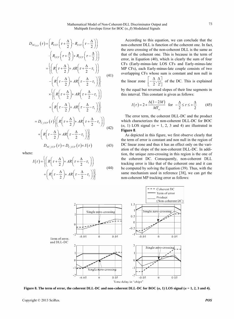
The error term, the coherent DLL-DC and the product which characterizes the non-coherent DLL-DC for BOC (α, 1) LOS signal (α = 1, 2, 3 and 4) are illustrated in Figure 8.
_ _NC CCF C CCFD D (43)
where:
1
1
2 2
2 2
I R AR
R AR
(44)
As depicted in this figure, we first observe clearly that the term of error is constant and non null in the region of DC linear zone and thus it has an effect only on the vari-ation of the slope of the non-coherent DLL-DC. In addi-tion, the unique zero-crossing in this region is the one of the coherent DC. Consequently, non-coherent DLL tracking error is like that of the coherent one and it can be computed by solving the Equation (39). Thus, with the same mechanism used in reference [38], we can get the non-coherent MP tracking error as follows:
Figure 8. The term of error, the coherent DLL-DC and non-coherent DLL-DC for BOC (α, 1) LOS signal (α = 1, 2, 3 and 4).
Mathematical Model of Non-Coherent-DLL Discriminator Output and Multipath Envelope Error for BOC (α, β) Modulated Signals
74
err
11
2, 1 1, 1
1
Tracking 11, 1 2,1
1
, 1
, f1 2
2 11 f
2 1 2
2 3 4 1 12 2
1 ,4 2 1 4 1
12
, for24 2 1
0, e
,
lsewh
k
t k t k
c
k
t k t kk
M
X
t M XM
AA
AM k
A dM
TM k k M k
A dM A M k
A Td T
M A
ere
or 0 1
or
for
d
d (46)
with
1
sc
kT
(47)
1
2,
2 11 1
2 4 2k
t k sc
M kd A k T
M
(48)
1
1,
2 31
2 4 2k
t k sc
M kd A k T1
M
(49)
11
4 2 2M
tM Xd A TM
(50)
4. Test of the Proposed Closed form Solutions
Computer implementations have been performed to test
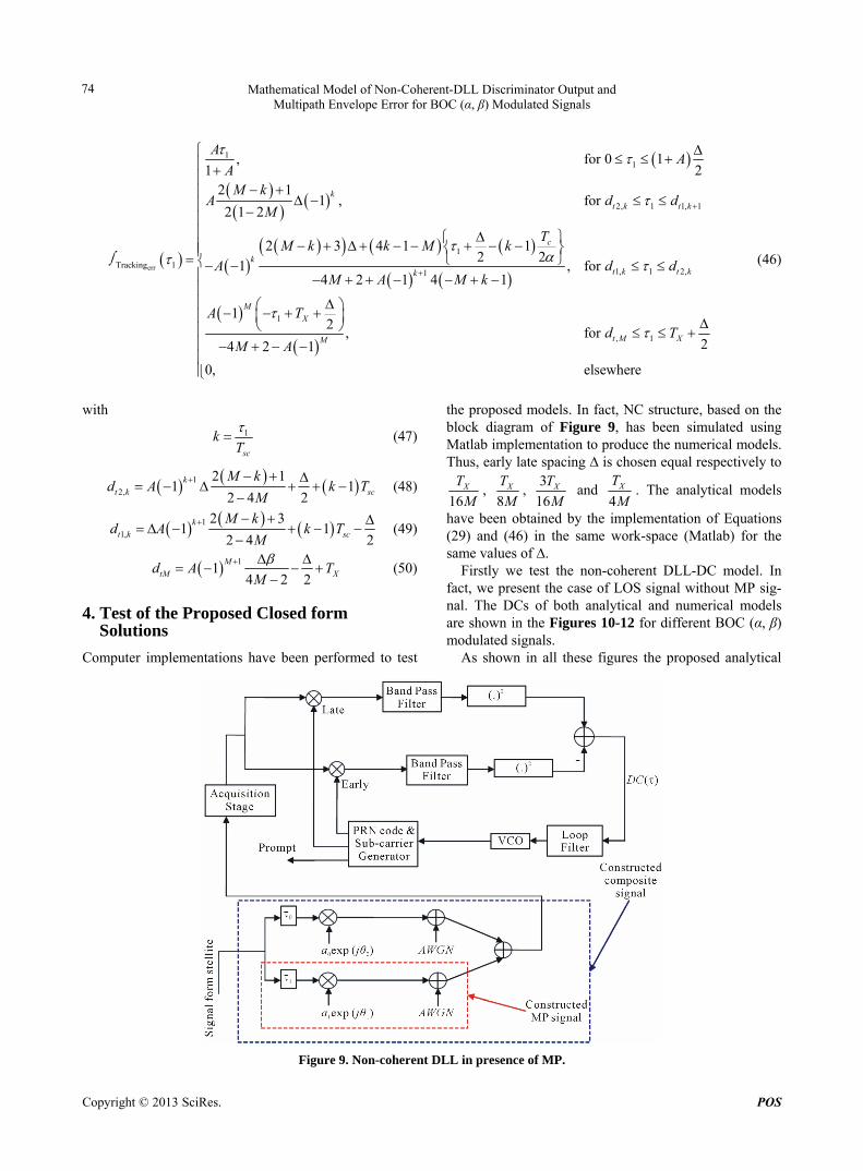
the proposed models. In fact, NC structure, based on the block diagram of Figure 9, has been simulated using Matlab implementation to produce the numerical models. Thus, early late spacing ∆ is chosen equal respectively to
16XT
M,
8XT
M,
3
16XT
M and
4XT
M. The analytical models
have been obtained by the implementation of Equations (29) and (46) in the same work-space (Matlab) for the same values of ∆.
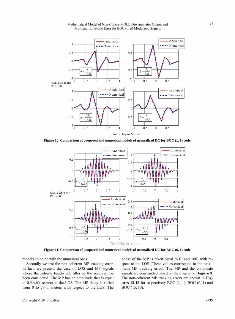
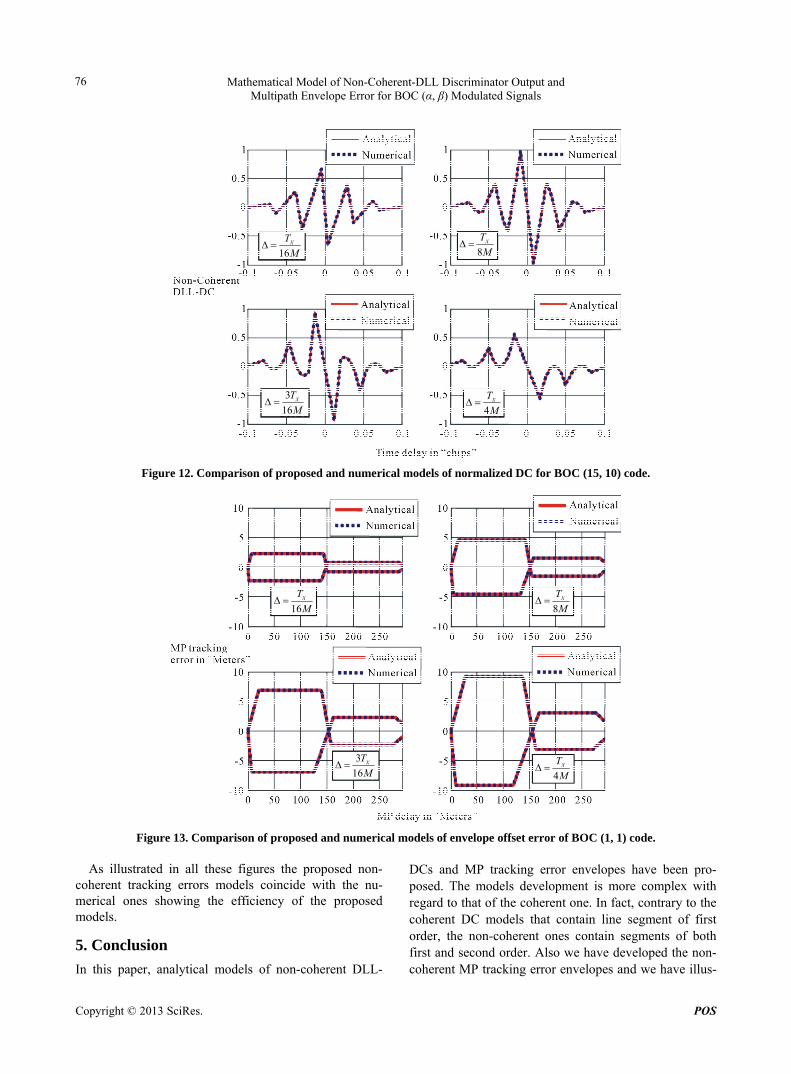
Firstly we test the non-coherent DLL-DC model. In fact, we present the case of LOS signal without MP sig-nal. The DCs of both analytical and numerical models are shown in the Figures 10-12 for different BOC (α, β) modulated signals.
As shown in all these figures the proposed analytical
Figure 9. Non-coherent DLL in presence of MP.
Copyright © 2013 SciRes. POS
Mathematical Model of Non-Coherent-DLL Discriminator Output and Multipath Envelope Error for BOC (α, β) Modulated Signals
75
16XT
M
8XT
M
4XT
M 3
16XT
M
Figure 10. Comparison of proposed and numerical models of normalized DC for BOC (1, 1) code.
16XT
M
8XT
M
4XT
M
3
16XT
M
Figure 11. Comparison of proposed and numerical models of normalized DC for BOC (6, 1) code. models coincide with the numerical ones.
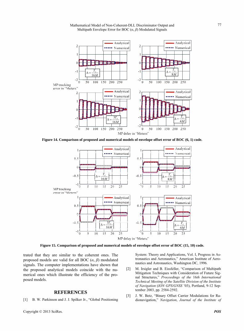
Secondly we test the non-coherent MP tracking error. In fact, we present the case of LOS and MP signals where the infinite bandwidth filter in the receiver has been considered. The MP has an amplitude that is equal to 0.5 with respect to the LOS. The MP delay is varied from 0 to TX in meters with respect to the LOS. The
phase of the MP is taken equal to 0˚ and 180˚ with re- spect to the LOS (These values correspond to the maxi- mum MP tracking error). The MP and the composite signals are constructed based on the diagram of Figure 9. The non-coherent MP tracking errors are shown in Fig- ures 13-15 for respectively BOC (1, 1), BOC (6, 1) and BOC (15, 10).
Copyright © 2013 SciRes. POS
Mathematical Model of Non-Coherent-DLL Discriminator Output and Multipath Envelope Error for BOC (α, β) Modulated Signals
76
16XT
M
8XT
M
4XT
M
3
16XT
M
Figure 12. Comparison of proposed and numerical models of normalized DC for BOC (15, 10) code.
16XT
M
8XT
M
4XT
M
3
16XT
M
Figure 13. Comparison of proposed and numerical models of envelope offset error of BOC (1, 1) code.
As illustrated in all these figures the proposed non- coherent tracking errors models coincide with the nu- merical ones showing the efficiency of the proposed models.
5. Conclusion
In this paper, analytical models of non-coherent DLL-
DCs and MP tracking error envelopes have been pro-posed. The models development is more complex with regard to that of the coherent one. In fact, contrary to the coherent DC models that contain line segment of first order, the non-coherent ones contain segments of both first and second order. Also we have developed the non- coherent MP tracking error envelopes and we have illus-
Copyright © 2013 SciRes. POS
Mathematical Model of Non-Coherent-DLL Discriminator Output and Multipath Envelope Error for BOC (α, β) Modulated Signals
77
16XT
M
4XT
M
8XT
M
3
16XT
M
Figure 14. Comparison of proposed and numerical models of envelope offset error of BOC (6, 1) code.
16XT
M
8XT
M
4XT
M
3
16XT
M
Figure 15. Comparison of proposed and numerical models of envelope offset error of BOC (15, 10) code. trated that they are similar to the coherent ones. The proposed models are valid for all BOC (α, β) modulated signals. The computer implementations have shown that the proposed analytical models coincide with the nu-merical ones which illustrate the efficiency of the pro-posed models.
REFERENCES
[1] B. W. Parkinson and J. J. Spilker Jr., “Global Positioning
System: Theory and Applications, Vol. I, Progress in As- tronautics and Aeronautics,” American Institute of Aero- nautics and Astronautics, Washington DC, 1996.
[2] M. Irsigler and B. Eissfeller, “Comparison of Multipath Mitigation Techniques with Consideration of Future Sig- nal Structures,” Proceedings of the 16th International Technical Meeting of the Satellite Division of the Institute of Navigation (ION GPS/GNSS ’03), Portland, 9-12 Sep- tember 2003, pp. 2584-2592.
[3] J. W. Betz, “Binary Offset Carrier Modulations for Ra- dionavigation,” Navigation, Journal of the Institute of
Copyright © 2013 SciRes. POS
Mathematical Model of Non-Coherent-DLL Discriminator Output and Multipath Envelope Error for BOC (α, β) Modulated Signals
78
Navigation, Vol. 48, No. 4, 2001, pp. 227-246.
[4] J. A. Avila-Rodriguez, G. W. Hein, S. Wallner, et al., “The MBOC Modulation: The Final Touch to the Galileo Frequency and Signal Plan,” Proceedings of the 20th In- ternational Technical Meeting of the Satellite Division of the Institute of Navigation (ION GPS’07), Fort Worth, 25-28 September 2007, pp. 1515-1529.
[5] G. W. Hein, J. A. Avila-Rodriguez, S. Wallner, et al., “MBOC: The New Optimized Spreading Modulation Re- commended for GALILEO L1 OS and GPS L1C,” Pro- ceedings of the IEEE/ION Position, Location, and Navi-gation Symposium, San Diego, 25-27 April 2006, pp. 883- 892.
[6] K. Borre, D. Akos, N. Bertelsen, P. Rinder and S. Jen- sen, “A Software- Defined GPS and Galileo Receiver: A Single-Frequency Approach,” Birkhäauser, Boston, 2007.
[7] L. Liu and M. Amin, “Multipath and Precorrelation Fil- tering Effect on GPS Noncoherent Early-Minus-Late Power Discriminators,” IEEE International Symposium of Signal Processing and Information Technology, Ath- ens, 21 December 2005.
[8] F. Nunes, F. Sousa and J. Leitao, “Gating Functions for Multipath Mitigation in GNSS BOC Signals,” IEEE Transactions on Aerospace and Electronic System, Vol. 43, No. 3, 2007, pp. 951-964. doi:10.1109/TAES.2007.4383585
[9] L. Boccia, G. Amendola and G. Di Massa, “Performance Evaluation of Shorted Annular Patch Antennas for High- Precision GPS Systems,” IET Microwaves, Antennas & Propagation, Vol. 1, No. 2, 2007, pp. 465-471. doi:10.1049/iet-map:20060025
[10] C. C. Counselman, “Multipath-Rejecting GPS Antennas,” Proceedings of the IEEE, Vol. 87, No. 1, 1999, pp. 86- 91. doi:10.1109/5.736343
[11] C.-L. Chang and J.-C. Juang, “An Adaptive Multipath Mi- tigation Filter for GNSS Applications,” EURASIP Jour- nal on Advances in Signal Processing, Vol. 2008, 2008, Article ID: 214815.
[12] G. Seco-Granados, J. A. Fernández-Rubio and C. Fer- nández-Prades, “ML Estimator and Hybrid Beamformer for Multipath and Interference Mitigation in GNSS Re- ceivers,” IEEE Transactions on Signal Processing, Vol. 53, No. 3, 2005, pp. 1194-1208.
[13] E. S. Lohan, R. Hamila, A. Lakhzouri and M. Renfors, “Highly Efficient Techniques for Mitigating the Effects of Multipath Propagation in DS-CDMA Delay Estima-tion,” IEEE Transactions on Wireless Communications, Vol. 4, No. 1, 2005, pp. 149-162.
[14] M. S. Braasch, “Performance Comparison of Multipath Mitigating Receiver Architectures,” Proceedings of the IEEE Aerospace Conference, Vol. 3, 2001, pp. 31309- 31315.
[15] Z. Zhang and C. L. Law, “Short-Delay Multipath Mitiga- tion Technique Based on Virtual Multipath,” IEEE An- tennas and Wireless Propagation Letters, Vol. 4, No. 1, 2005, pp. 344-348. doi:10.1109/LAWP.2005.857038
[16] S. L. Elena, L. Abdelmonaem and R. Markku, “Feed
forward Delay Estimators in Adverse Multipath Propaga- tion for Galileo and Modernized GPS Signals,” Hindawi Vol. 8, 2009, pp. 1434-1435. doi:10.1109/LAWP.2009.2012977
[17] M. Z. H. Bhuiyan, E. S. Lohan and M. Renfors, “Code Tracking Algorithms for Mitigating Multipath Effects in Fading Channels for Satellite-Based Positioning,” EUR- ASIP Journal on Advances in Signal Processing, Vol. 2008, 2008, Article ID: 863629, 17 pages.
[18] J. Van Dierendonck, P. Fenton and T. Ford, “Theory and Performance of Narrow Correlator Spacing in a GPS Re- ceiver,” Journal of the Institute of Navigation, Vol. 39, No. 3, 1992, pp. 265-283.
[19] R. Van Nee, J. Siereveld, P. Fenton and B. Townsend, “The Multipath Estimating Delay Lock Loop: Approach- ing Theoretical Accuracy Limits,” Proceeding of IEEE Position Location and Navigation Symposium, Las Vegas, 11-15 April 1994, pp. 246-251.
[20] K. Rouabah and D. Chikouche, “GPS/Galileo Multipath Detection and Mitigation Using Closed-Form Solutions,” Mathematical Problems in Engineering, Vol. 2009, 2009, Article ID: 106870, 20 pages.
[21] M. Laxton, “Analysis and Simulation of a New Code Tracking Loop for GPS Multipath Mitigation,” M.S. The- sis, Air Force Institute of Technology, Wright-Patterson AFB, 1996.
[22] B. Townsend, D. J. R. van Nee, P. Fenton and K. Van Dierendonck, “Performance Evaluation of the Multipath Estimating Delay Lock Loop,” Proceedings of the Na- tional Technical Meeting, Anaheim, 18-20 January 1995, pp. 277-283.
[23] B. Townsend, J. Weibe and A. Jakab, “Results and Ana- lysis of Using the MEDLL Receiver as a Multipath Me- ter,” Proceedings of ION National Technical Meeting, Anahiem, 26-29 January 2000.
[24] M. Sahmoudi and R. Landry Jr., “Multipath Mitigation Techniques Using Maximum-Likelihood Principle,” In- side GNSS, Vol. 3, No. 8, 2008, pp. 24-29.
[25] M. Sahmoudi and M. G. Amin, “Fast Iterative Maxi- mum-Likelihood Algorithm (FIMLA) for Multipath Mi- tigation in the Next Generation of GNSS Receivers,” IEEE Transactions on Wireless Communications, Vol. 7, No. 11, 2008, pp. 4362-4374. doi:10.1109/T-WC.2008.070700
[26] O. Julien, C. Macabiau, M. E. Cannon and G. Lachapelle, “ASPeCT: Unambiguous Sine-BOC(n,n) Acquisition/ Tracking Technique for Navigation Applications,” IEEE Transactions on Aerospace and Electronic Systems, Vol. 43, No. 1, 2007, pp. 150-162. doi:10.1109/TAES.2007.357123
[27] A. Burian, E. S. Lohan and M. K. Renfors, “Efficient Delay Tracking Methods with Sidelobes Cancellation for BOC-Modulated Signals,” EURASIP Journal on Wireless Communications and Networking, Vol. 2007, 2007, Arti- cle ID: 072626. doi:10.1155/2007/72626
[28] Y. Zhou, X. Hu and Z. Tang, “Unambiguous Tracking Technique for Sin-BOC(1,1) and MBOC(6,1,1/11) Sig- nals,” Proceedings of the 2nd International Conference
Copyright © 2013 SciRes. POS
Mathematical Model of Non-Coherent-DLL Discriminator Output and Multipath Envelope Error for BOC (α, β) Modulated Signals
Copyright © 2013 SciRes. POS
79
on Future Computer and Communication (ICFCC’10), 21-24 May 2010, pp. V1188-V1190.
[29] K. Rouabah, M. Flissi, S. Attia and D. Chikouche, “Un- ambiguous Multipath Mitigation Technique for BOC(n,n) and MBOC-Modulated GNSS Signals,” International Journal of Antennas and Propagation, Vol. 2012, 2012, Article ID: 895390, 13 pages. doi:10.1155/2012/895390
[30] Z. Yao, M. Lu and Z. Feng, “Unambiguous Technique for Multiplexed Binary Offset Carrier Modulated Signals Tracking,” IEEE Signal Processing Letters, Vol. 16, No. 7, 2009, pp. 608-611. doi:10.1109/LSP.2009.2020462
[31] F. Dovis, P. Mulassano and L. Lo Presti, “A Novel Algo- rithm for the Code Tracking of BOC(n,n) Modulated Sig- nals,” Proceedings of the 18th International Technical Meeting of the Satellite Division of The Institute of Navi- gation (ION GNSS’05), Long Beach, 13-16 September 2005, pp. 152-155.
[32] G. Dempster and J. Wu, “Code Discriminator for Multi- plexed Binary Offset Carrier Modulated Signals,” Elec- tronics Letters, Vol. 44, No. 5, 2008, pp. 384-385. doi:10.1049/el:20080138
[33] J. Wu and A. G. Dempster, “Applying a BOC-PRN Dis- criminator to Cosine Phased BOC(fs,fc) Modulation,” Electronics Letters, Vol. 45, No. 13, 2009, pp. 689-691. doi:10.1049/el.2009.0374
[34] K. Rouabah, D. Chikouche, F. Bouttout, R. Harba and P. Ravier, “GPS/Galileo Multipath Mitigation Using the First Side Peak of Double Delta Correlator,” Wireless Personal Communications, Vol. 60, No. 2, 2010, pp. 321- 333. doi:10.1007/s11277-010-9946-2
[35] J. Winkel, “Modeling and Simulating GNSS Signal Structures and Receivers,” University of Federal Armed Forces Munich, Neubiberg, 2003.
[36] F. Nunes, F. Sousa and J. Leitão, “Improving Multipath Mitigation in GPS/Galileo BOC Signals with Gating Functions,” Proceedings of the 61st Annual Meeting of the Institute of Navigation ION-AM 2005, Cambridge, June 2005, pp. 498-507.
[37] B. R. Harris and G. E. Lightsey, “A General Model of Multipath Error for Coherently Tracked BOC Modulated Signals,” IEEE Journal of Selected Topics in Signal Pro- cessing, Vol. 3, No. 4, 2009, pp. 682-694. doi:10.1109/JSTSP.2009.2024106
[38] S. Zitouni., K. Rouabah, S. Atia and D. Chikouche, “Comments on ‘A General Model of Multipath Error for Coherently Tracked BOC Modulated Signals’,” Wireless Personal Communications, Springer, 2012, in Press.
[39] M. Braasch, “On the Characterization of Multipath Errors in Satellite-Based Precision Approach and Landing Sys- tems,” Ph.D. Thesis, Ohio University, Athens, 1992.