Stimulators, Isolators - Experimetria · The DS8000 has 8 analog outputs, 8 TTL outputs and 8...
12
Transcript of Stimulators, Isolators - Experimetria · The DS8000 has 8 analog outputs, 8 TTL outputs and 8...


23
ST
IMU
LA
TO
RS
, ISO
LA
TO
RS
Feature Input Output COmpatIble StImulatOr:DlS100
Biphasic,Digital Analog
Modeling
Digital from DS8000
0-100 V1 μA to 10 mA
a320
SIU/built-in stimulator
TTL 0-100 V1 μA to 10 mA
a365
Mono/Biphasic TTL ±100 V1 μA to 10 mA
a385
High Current TTL ±36 V10 μA to 100 mA
a395
Analog Analog±10 volts
±70 V1 μA to 10 mA
DuO 773
Intracellular Amplifier
Analog 0-1 volt
±500 nA
Stimulators, IsolatorsStimulators, Isolators
DS8000
DS8000
DS8000
DS8000
DS8000
DS8000
A300A31
0
A300
A300
A300
A300
A310
A310
A310
A310
Prices shown are in U.S. dollars. Actual charges will vary because of import duty, freight, and currency fluctuations. To obtain an exact quotation, contact your WPI office.
World Precision Instruments • tel: 941-371-1003 • Fax: 941-377-5428 • e-mail: [email protected] • Internet: www.wpiinc.com
24
ST
IMU
LA
TO
RS
, IS
OL
AT
OR
S
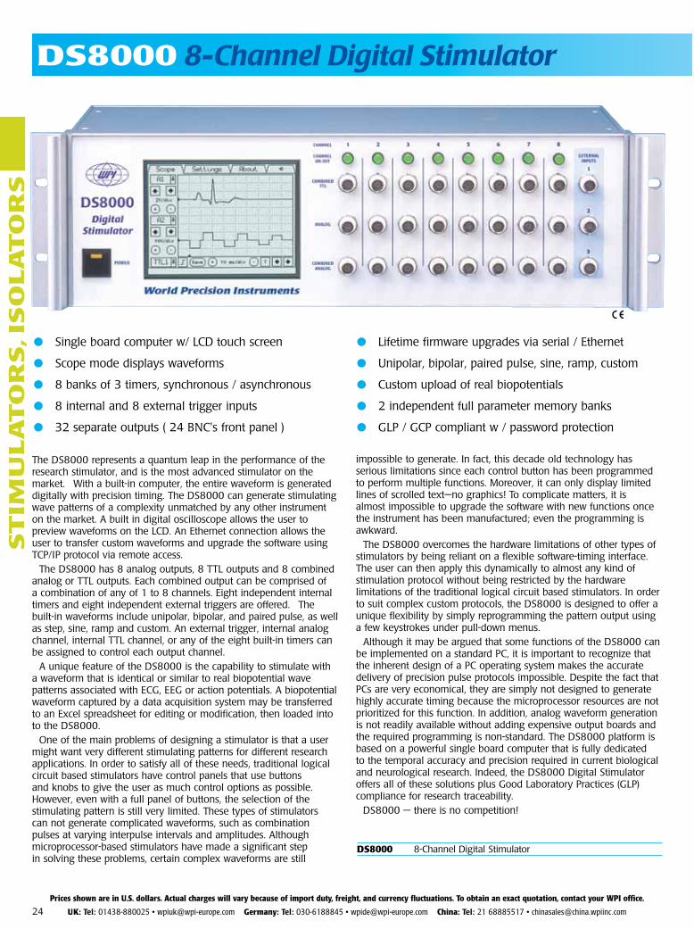
● Single board computer w/ LCD touch screen
● Scope mode displays waveforms
● 8 banks of 3 timers, synchronous / asynchronous
● 8 internal and 8 external trigger inputs
● 32 separate outputs ( 24 BNC's front panel )
DS8000 8-Channel Digital Stimulator
● Lifetime firmware upgrades via serial / Ethernet
● Unipolar, bipolar, paired pulse, sine, ramp, custom
● Custom upload of real biopotentials
● 2 independent full parameter memory banks
● GLP / GCP compliant w / password protection
The DS8000 represents a quantum leap in the performance of the research stimulator, and is the most advanced stimulator on the market. With a built-in computer, the entire waveform is generated digitally with precision timing. The DS8000 can generate stimulating wave patterns of a complexity unmatched by any other instrument on the market. A built in digital oscilloscope allows the user to preview waveforms on the LCD. An Ethernet connection allows the user to transfer custom waveforms and upgrade the software using TCP/IP protocol via remote access.
The DS8000 has 8 analog outputs, 8 TTL outputs and 8 combined analog or TTL outputs. Each combined output can be comprised of a combination of any of 1 to 8 channels. Eight independent internal timers and eight independent external triggers are offered. The built-in waveforms include unipolar, bipolar, and paired pulse, as well as step, sine, ramp and custom. An external trigger, internal analog channel, internal TTL channel, or any of the eight built-in timers can be assigned to control each output channel.
A unique feature of the DS8000 is the capability to stimulate with a waveform that is identical or similar to real biopotential wave patterns associated with ECG, EEG or action potentials. A biopotential waveform captured by a data acquisition system may be transferred to an Excel spreadsheet for editing or modification, then loaded into to the DS8000.
One of the main problems of designing a stimulator is that a user might want very different stimulating patterns for different research applications. In order to satisfy all of these needs, traditional logical circuit based stimulators have control panels that use buttons and knobs to give the user as much control options as possible. However, even with a full panel of buttons, the selection of the stimulating pattern is still very limited. These types of stimulators can not generate complicated waveforms, such as combination pulses at varying interpulse intervals and amplitudes. Although microprocessor-based stimulators have made a significant step in solving these problems, certain complex waveforms are still
impossible to generate. In fact, this decade old technology has serious limitations since each control button has been programmed to perform multiple functions. Moreover, it can only display limited lines of scrolled text—no graphics! To complicate matters, it is almost impossible to upgrade the software with new functions once the instrument has been manufactured; even the programming is awkward.
The DS8000 overcomes the hardware limitations of other types of stimulators by being reliant on a flexible software-timing interface. The user can then apply this dynamically to almost any kind of stimulation protocol without being restricted by the hardware limitations of the traditional logical circuit based stimulators. In order to suit complex custom protocols, the DS8000 is designed to offer a unique flexibility by simply reprogramming the pattern output using a few keystrokes under pull-down menus.
Although it may be argued that some functions of the DS8000 can be implemented on a standard PC, it is important to recognize that the inherent design of a PC operating system makes the accurate delivery of precision pulse protocols impossible. Despite the fact that PCs are very economical, they are simply not designed to generate highly accurate timing because the microprocessor resources are not prioritized for this function. In addition, analog waveform generation is not readily available without adding expensive output boards and the required programming is non-standard. The DS8000 platform is based on a powerful single board computer that is fully dedicated to the temporal accuracy and precision required in current biological and neurological research. Indeed, the DS8000 Digital Stimulator offers all of these solutions plus Good Laboratory Practices (GLP) compliance for research traceability.
DS8000 — there is no competition!
Prices shown are in U.S. dollars. Actual charges will vary because of import duty, freight, and currency fluctuations. To obtain an exact quotation, contact your WPI office.
UK: Tel: 01438-880025 • [email protected] Germany: Tel: 030-6188845 • [email protected] China: Tel: 21 68885517 • [email protected]
DS8000 8-Channel Digital Stimulator

25
ST
IMU
LA
TO
RS
, ISO
LA
TO
RS
A quantum leap in the performance of the research stimulator
Paired Pulse Protocol
The DS8000’s Paired Pulse function allows the user to generate triggered paired pulses (including refractory period) from a single channel without the use of a train function. WPI’s paired pulse algorithm simplifies the arduous repetitive task normally associated with manual resetting of interpulse intervals in refractory studies. Auto-increment eliminates the need to overlap train functions from multiple channels to generate a complete protocol. Thus, there is a significant reduction in setup time and a minimization of the potential for human error during interactive protocol modification.
Fig. 1 shows Channel 1 configured in the TRIGGERED PAIRED PULSE mode. In this example, a dual pulse event occurs synchronously with each trigger pulse from Channel 8, which is set to trigger every 300 ms. The initial interpulse interval is set to 20 ms. Subsequent interpulse intervals are automatically incremented by 35 ms for each three consecutive paired pulse events. The resulting paired pulse is displayed in the lower trace on the DS8000 scope (Fig. 2). The upper trace shows the master trigger pulse set up on Channel 8.
Soft Keys and GuI interface
The DS8000 employs “soft keys”, which are programmable controls widely used in several menu options to sequentially change the numerical value of any variable waveform parameter. The DS8000’s soft keys are easily recognized as single or double “+” and “-“ signs located adjacent to a parameter value box (Fig. 1). Soft keys provide quick and easy access to modify parameter values on the fly during an experiment. The GUI interface (Fig. 3) enables the user to assign the incremental value of the soft key to suit the needs of the experiment. Alternatively, a pop-up numeric keypad is accessible for each parameter to program a precise value that is not a multiple of the softkey-preset increment.
Combined Channel assignment matrices
The CTTL (COMBINED TTL matrix) and CA (COMBINED ANALOG matrix) screens permit the assignment of any combination of the 8 available TTL or Analog signals to any permutation of the respective (8) CTTL or (8)
Fig. 1Channel Settings
Fig. 4Combined TTL Matrix
Fig. 3Graphic User Interface
Fig. 2Scope Display
CA BNC outputs. The setup in Fig. 4 indicates that all TTL channels are assigned to their respective CTTL outputs with the exception of the output of CTTL 1, which is assigned a combination of the TTL signals from channels 4 and 5. Changing assignments is as easy as checking the associated box. The CA tab reveals an identical matrix for programming the COMBINED ANALOG BNC outputs.
DS8000 SPecIfIcATIOnSTiming parameTers
Period (total signal width) 0.04 ms to 10,737,418.24 ms
Pulse width 0.02 ms to 10,737,418.24 ms
BiPolar gaP width 0.00 ms to 10,737,418.24 ms
oPerating Modes Free run, triggered, gated, Train, DC
triggers 8 External, manual, TTL 1-8, combined TTL 1-8, timer start or stop
train events 1-199
train Pulse width 0.02 ms to 10,737,418.24 ms (3 hours)
train Pulse delaY 0.04 ms to 10,737,418.24 ms
train Period 0.06 ms to 10,737,418.24 ms
BNC OuTpuT CONNECTOrs Analog, combined analog, combined digital (TTL)
waveforMs unipolar, bipolar, rectangular, sine, ramp, step, paired pulse, custom defined
CusTOm wAvEFOrm 12 steps/ voltage point (1025 if remote controlled)
variaBle steP waveforM 100 points (1025 if remote controlled)
outPut noise < 5 mv rms
TimiNg ACCurACy < 100 ppm
outPut voltage resolution 5 mv
mAx. OuTpuT vOLTAgE +/-10v @ +/- 10 mA @ 0.005 v/step
OuTpuT impEDANCE 50 Ohm Analog, < 1 ohm Combined Analog
ExTErNAL TriggEr syNC 40 µs minimum pulse TTL, CmOs 20 µs glitch and spike protection
DigiTAL i/O 5v max 10 mA (input); 25v @ 500 mA (open collector output)
Mains voltage 85-260 v AC, 45-65 Hz 50w
diMensions 13.3 cm x 42.5 cm x 25.4 cm 5.25” x 16.73” (19” rack) x 10”
shiPPing weight 12 lb (5.5 kg)
aMBient teMPerature -10 to +40 °C; -20 to +50 °C (internal)
huMiditY max. 95% relative humidity, non-condensing
SPECIFICATIONS SUBJECT TO CHANGE WITHOUT NOTICE.
Prices shown are in U.S. dollars. Actual charges will vary because of import duty, freight, and currency fluctuations. To obtain an exact quotation, contact your WPI office.
World Precision Instruments • tel: 941-371-1003 • Fax: 941-377-5428 • e-mail: [email protected] • Internet: www.wpiinc.com
26
ST
IMU
LA
TO
RS
, IS
OL
AT
OR
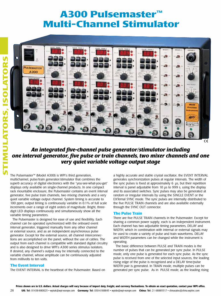
SA300 Pulsemaster™
Multi-channel Stimulator
The Pulsemaster™ (Model A300) is WPI’s third generation, multichannel, pulse/train gen er a tor/stimulator that combines the superb accuracy of dig i tal elec tron ics with the “you-see-what-you-get” displays only available on single-channel products. In one compact rack mountable enclosure, the Pulsemaster contains an event interval generator, five pulse train channels, two mixing channels and a very quiet variable voltage output channel. Sys tem timing is accurate to 100 ppm; output timing is continuously variable in 0.1% of full scale in cre ments over a range of eight orders of magnitude. Bright, three-digit LED displays continuously and simultaneously show all the variable timing pa ram e ters.
The Pulsemaster is designed for ease of use and flex i bil i ty. Each channel can be operated synchronized with the onboard event interval generator, trig gered manually from any other channel or external source, and as an in de pen dent asynchronous pulse generator. Except for the external source, all channel in ter con nec-tions are accomplished on the panel, without the use of cables. The output from each channel is compatible with standard digital circuitry and is also designed to drive WPI’s A300 series stimulus iso la tors. If desired, any channel’s output may be in ter nal ly connected to the variable channel, whose am pli tude can be continuously adjusted from mil li volts to ten volts.
The event IntervalThe EVENT INTERVAL is the heartbeat of the Pulsemaster. Based on
a high ly ac cu rate and stable crystal oscillator, the EVENT INTERVAL generates syn chro ni za tion pulses at regular intervals. The width of the sync pulses is fixed at approximately 6 µs, but their repetition interval is panel adjustable from 10 µs to 999 s, using the display and its associated switches. Sync pulses may also be generated at random or irregular intervals by using the SINGLE EVENT or the EXTernal SYNC mode. The sync pulses are internally dis trib ut ed to the five PULSE TRAIN channels and are also available externally through the SYNC OUT connector.
The Pulse TrainThere are five PULSE TRAIN channels in the Pulsemaster. Except for sharing a common power supply, each is an independent instrument. Each channel has two adjustable timing parameters, DE LAY and WIDTH, which in com bi na tion with in ter nal or external signals may be used to create a variety of pulse and train waveforms. DELAY and WIDTH parameters can be changed while the instrument is operating.
The basic difference between PULSE and TRAIN modes is the number of pulses that can be generated per sync pulse. In PULSE mode, only one pulse is generated for each sync pulse. As the sync pulse is received from one of the selected input sources, the leading rising edge of the pulse is recognized and a DELAY time/pulse WIDTH pair is generated. In TRAIN mode, multiple pulses can be generated per sync pulse. As in PULSE mode, as the lead ing rising
An integrated five-channel pulse generator/stim u la tor includingone in ter val generator, five pulse or train channels, two mixer chan nels and one
very quiet vari able voltage out put stage
Prices shown are in U.S. dollars. Actual charges will vary because of import duty, freight, and currency fluctuations. To obtain an exact quotation, contact your WPI office.
UK: Tel: 01438-880025 • [email protected] Germany: Tel: 030-6188845 • [email protected] China: Tel: 21 68885517 • [email protected]
27
ST
IMU
LA
TO
RS
, ISO
LA
TO
RS
A300 PULSeMASTeR SPecIfIcATIOnS
eVent InterVal CHannel
Operating Modes EXTernal SYNC, SINGLE EVENT, CON TIN U OUS ON
Input EXT SYNC accepts ≥ 1µs pulses; TTL, CMOS,
RS232C compatible
Timing EVENT INTERVAL 10 µs to 999 s (100 kHz - 0.001 Hz),
±0.1% of full scale, continuously variable in 0.1% of full
scale increments, through three orders of magnitude, in
six ranges
Output SYNC OUT pulse of ≈6 µs, TTL, 5 V CMOS compatible
pulSe traIn CHannel (5 provided)
Operating Modes EXTernal SYNC, SELF SYNC, manual SINGLE event,
sync from Event Interval, sync from any of other four
Pulse Trains, sync from one of the MIXers, off,
TRAIN/PULSE
Input EXT SYNC accepts ≥ 1µs pulses; TTL, CMOS,
RS232C compatible
Timing DELAY and WIDTH 10 µs to 999 s, ±0.1% of full scale,
continuously variable in 0.1% of full scale increments,
through three orders of magnitude, in six ranges
(.0005 Hz to 50 kHz in the SELF SYNC mode)
Output OUTPUT PULSE/TRAIN of preset timing, TTL, 5 V
CMOS compatible, 4 mA sink and source
mIXer CHannel (2 provided)
Inputs Any combination of an EXTernal pulse, the outputs of
the five Pulse Train channels, and DC continuous ON/
DC MOMentary EXT INPUT accepts ≥ 1µs pulses; TTL,
CMOS, RS232C compatible
Output OUTPUT, TTL, 5V CMOS compatible, 4 mA sink and
source
VarIable CHannel
Inputs Output from any one PULSE TRAIN channel
or one of the two MIXER channels or DC
Output 0 to +1 V low range, 1 mV resolution
0 to +10 V high range, 10 mV resolution
5 mA max sink and source
Output Impedance <1 ohm
Noise <500 µV peak @ 100 kHz bandwidth, PULSED mode
<500 µV, wide band, DC mode
Signal Ground Floating, i.e., not connected to chassis
pOWer 95-135 V or 220-240 V, 50/60 Hz
batterIeS Three 1.2 V DC, size AA, NiMH batteries
DImenSIOnS 8.5 x 19 x 8.75 in. (22 x 45 x 22 cm)
SHIppInG WeIGHt 21 lb (9.5 kg)
edge of the sync pulse is recognized, a pulse WIDTH/DELAY pair is gen er at ed. Pulses (WIDTH/DELAY pairs) are con tin u ous ly produced as long as the sync pulse is still “high” at the con clu sion of the DELAY time.
By means of the INPUT SELECT switch, sync pulses can be received from an external source through the EXT SYNC connector, manually by the SIN GLE switch, from any of the other PULSE TRAIN channels, or one of the MIXER channels. The chan nel may also be disabled by switching to one of the OFF positions.
EXT SYNC position: permits control of the PULSE TRAIN channel by other instruments and computers.
SELF SYNC position: the channel becomes a free running pulse gen-er a tor. The symmetry of the wave form can be adjusted by varying the DELAY and/or the WIDTH times.
SINGLE EVENT position: pulses are generated at your discretion. Every time the SINGLE button is pressed, one and only one DELAY/WIDTH se quence is generated.
EI position: connects the output of the EVENT INTERVAL generator to the input of the PULSE TRAIN channel. For every output sync pulse from the EVENT INTERVAL generator, one DELAY/WIDTH pair is generated.
PT positions (4): internally connect the outputs from the respective PULSE TRAIN chan nels to the input of this PULSE TRAIN channel. In the PULSE mode, for every OUTPUT pulse from the other selected PULSE TRAIN channel, one DELAY/WIDTH pair is generated from this channel. In the TRAIN mode, puls es are generated from this channel as long as the pulse from the other channel remains “high.”
MIX positions (2): internally connect the outputs from the respective MIXER chan nels to the input of this PULSE TRAIN channel. In the PULSE mode, for every OUT PUT pulse from the MIXER channel, one DELAY/WIDTH pair is gen er at ed from this channel. In TRAIN mode, pulses are generated from this chan nel as long as the pulse from the MIXER chan nel remains “high.”
OUTPUT connector: supplies the wave forms generated by the PULSE TRAIN channel. This OUTPUT is designed to drive WPI’s A300 series stimulus iso la tors. It is also useful for syn chro niz ing other in stru ments (recorders, os cil lo scopes, com put ers, etc.) with the pulses generated from the Pulsemaster.
The MixerThe MIXER does what its name im plies, it combines any or all of the outputs of the PULSE TRAIN channels with ex ter nal signals into one wave form. It can also provide a continuous (DC ON) or mo men tary (DC MOM) “high” level sig nal. The Mixer OUTPUT con nec tor sup-plies the com bi na tion wave forms gen er at ed by the MIX ER channel to drive WPI’s A300 series stimulus iso la tors or to syn chro nize the operation of other in stru ments with the Pulsemaster.
The Variable channelThe VARIABLE channel can replicate the OUT PUT waveforms from any of the PULSE TRAIN or MIX ER channels at amplitudes that can be varied from millivolts to ten volts. The channel also pro vides a very low noise, ad just able DC voltage source: the DC mode which converts the VARI ABLE chan nel into a constant voltage source. The OUTPUT con nec tor supplies the am pli tude mod i fied wave form or the DC voltage level of the VARI ABLE chan nel.
Prices shown are in U.S. dollars. Actual charges will vary because of import duty, freight, and currency fluctuations. To obtain an exact quotation, contact your WPI office.
World Precision Instruments • tel: 941-371-1003 • Fax: 941-377-5428 • e-mail: [email protected] • Internet: www.wpiinc.com
SYS-A300 Pulsemaster™ Multi-Channel Stimulator Specify line voltage

28
ST
IMU
LA
TO
RS
, IS
OL
AT
OR
S
A310 AccUPULSeR™ SPecIfIcATIOnStImInG parameterS
EVENT INTERVAL 100 µs to1000 s*
EVENT DELAY 10 µs to 100 s *
PULSE WIDTH 10 µs to 100 s *
TRAIN DURATION (ENVELOPE) 100 µs to 1000 s*
PULSE INTERVAL 20 µs to 100 s*
OutputS
SYNC 5 µs, TTL, and 5 V CMOS com pat i ble, 20 mA max.
MONITOR 10-15 V, 50 mA max.
ISOLATOR TTL & 5 V CMOS com pat i ble, 20mA max.
VARIABLE (Pos or Neg) PULSED/DC LOW RANGE HIGH RANGE Range 0 to ±1 V 0 to ±10 V Resolution 1 mV 10 mV
NOISE Pulsed at 100 kHz bandwidth <500 µV DC Wide Band <500 µV
OUTPUT IMPEDANCE <1 ΩInputS
EXTERNAL SYNC Accepts 1-µs min i mum pulses TTL, CMOS compatible
EXTERNAL GATE Accepts 1-µs pulse to continuous TTL, CMOS compatible
pOWer 95-130 V or 190-260 V, switch selectable single phase, 50/60 Hz
DImenSIOnS 17 x 5.25 x 10 in. (43 x 13 x 25 cm)
SHIppInG WeIGHt 14 lb (6.4 kg)
*Continuously variable in six ranges. All accuracies better than 1% of set value. 50kHz maximum pulse frequency.
Combining the accuracy of dig i tal electronics with the con ve nience of analog controlsA pulse generator/stimulator combining the reproducibility and accuracy of digital electronics with the fine resolution and continuous adjustment pos si ble with analog circuitry. All timing pa ram e ters are entered with ten-turn readable po ten ti om e ters and six-position range switches. Outputs are ac cu rate to within 1% of the set value.
pulses can be created in continuous run, single-shot, or train/burst modes. Duration of the train/burst is easily controlled using the onboard envelope generator or by using either of two external gating inputs. Used in con junc tion with the A360, A365, A385, or A395, bipolar pulses or trains may be easily produced. Output stimulus can be fed through the Duo 773 for iontophoresis. Footswitch allows hands-free operation.
three separate outputs are available on the front panel. A Monitor output provides 10-15 V signals (up to 50 mA) for viewing the output on an os cil lo scope or for controlling other devices. The stimulator’s signal, si mul ta neous ly available at the Isolator output, is sufficient to drive any WPI A300 Series stimulus isolator (A360, A365, or A385) and is also TTL and CMOS compatible. The Variable output can provide signals varying between ±10 V with a resolution of 1 mV. Separate variable outputs are provided for positive and negative signals.
Stimulus Isolator (A360)
A310 Accupulser™
Optional footswitch #3259
Prices shown are in U.S. dollars. Actual charges will vary because of import duty, freight, and currency fluctuations. To obtain an exact quotation, contact your WPI office.
UK: Tel: 01438-880025 • [email protected] Germany: Tel: 030-6188845 • [email protected] China: Tel: 21 68885517 • [email protected]
SYS-A310 Accupulser™ Signal Generator Specify line voltage
OPTIOnAL AcceSSORIeS3259 Footswitch for A3102933 Rack Mount Kit, 51⁄4 in. high
29
ST
IMU
LA
TO
RS
, ISO
LA
TO
RS
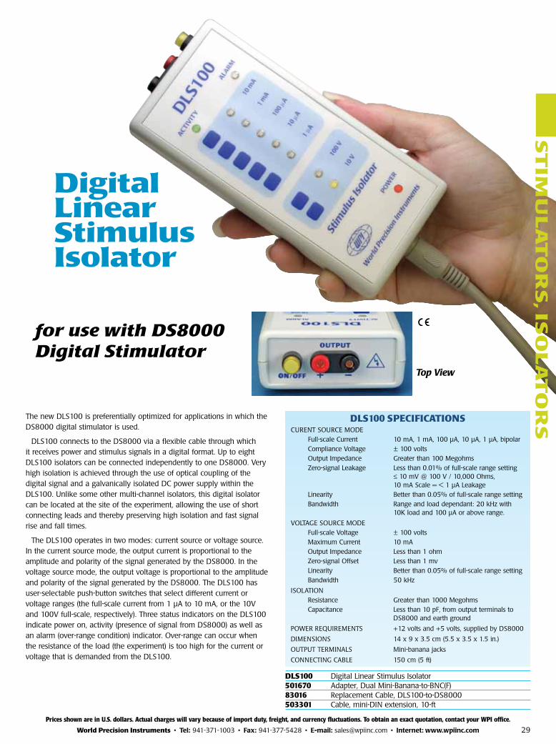
Digital Linear Stimulus Isolator
The new DLS100 is preferentially optimized for applications in which the DS8000 digital stimulator is used.
DLS100 connects to the DS8000 via a flexible cable through which it receives power and stimulus signals in a digital format. Up to eight DLS100 isolators can be connected independently to one DS8000. Very high isolation is achieved through the use of optical coupling of the digital signal and a galvanically isolated DC power supply within the DLS100. Unlike some other multi-channel isolators, this digital isolator can be located at the site of the experiment, allowing the use of short connecting leads and thereby preserving high isolation and fast signal rise and fall times.
The DLS100 operates in two modes: current source or voltage source. In the current source mode, the output current is proportional to the amplitude and polarity of the signal generated by the DS8000. In the voltage source mode, the output voltage is proportional to the amplitude and polarity of the signal generated by the DS8000. The DLS100 has user-selectable push-button switches that select different current or voltage ranges (the full-scale current from 1 µA to 10 mA, or the 10V and 100V full-scale, respectively). Three status indicators on the DLS100 indicate power on, activity (presence of signal from DS8000) as well as an alarm (over-range condition) indicator. Over-range can occur when the resistance of the load (the experiment) is too high for the current or voltage that is demanded from the DLS100.
DLS100 SPecIfIcATIOnSCURENT SOURCE MODE Full-scale Current 10 mA, 1 mA, 100 µA, 10 µA, 1 µA, bipolar Compliance Voltage ± 100 volts Output Impedance Greater than 100 Megohms Zero-signal Leakage Less than 0.01% of full-scale range setting ≤ 10 mV @ 100 V / 10,000 Ohms, 10 mA Scale = < 1 µA Leakage Linearity Better than 0.05% of full-scale range setting Bandwidth Range and load dependant: 20 kHz with 10K load and 100 µA or above range.
VOLTAGE SOURCE MODE Full-scale Voltage ± 100 volts Maximum Current 10 mA Output Impedance Less than 1 ohm Zero-signal Offset Less than 1 mv Linearity Better than 0.05% of full-scale range setting Bandwidth 50 kHz
ISOLATION Resistance Greater than 1000 Megohms Capacitance Less than 10 pF, from output terminals to DS8000 and earth ground
POWER REQUIREMENTS +12 volts and +5 volts, supplied by DS8000
DIMENSIONS 14 x 9 x 3.5 cm (5.5 x 3.5 x 1.5 in.)
OUTPUT TERMINALS Mini-banana jacks
CONNECTING CABLE 150 cm (5 ft)
Top View
for use with DS8000 Digital Stimulator
ST
IMU
LA
TO
RS
, ISO
LA
TO
RS
Prices shown are in U.S. dollars. Actual charges will vary because of import duty, freight, and currency fluctuations. To obtain an exact quotation, contact your WPI office.
World Precision Instruments • tel: 941-371-1003 • Fax: 941-377-5428 • e-mail: [email protected] • Internet: www.wpiinc.com
DLS100 Digital Linear Stimulus Isolator501670 Adapter, Dual Mini-Banana-to-BNC(F) 83016 Replacement Cable, DLS100-to-DS8000503301 Cable, mini-DIN extension, 10-ft

30
ST
IMU
LA
TO
RS
, IS
OL
AT
OR
S
Timing
Pulse interval and width are set with single-turn continuously variable con trols from 5 ms to 5.5 s in three ranges. Pulse width is continuously variable from 50 µs to 550 ms in four ranges.
Modes of operation
In FREE RUN, Isostim™ generates con tin u ous square waves. In EXT GATE or EXT SYNC modes, externally applied pulses can generate trains or single events. Single pulses of finite duration can be produced using a push-button on the instrument’s front panel. EXT/DC mode converts Isostim to a passive stimulus isolator.
Dual tone audible alarm
A tone sounds when an open circuit is detected or when system compliance is reached. A second tone, which sounds when a signal is applied to the input, can only be heard if the batteries have sufficient charge to operate the isolator. A violation light advises when pulse width exceeds the interval.
ISOSTIM™ SPecIfIcATIOnStImInG parameterS
Interval 5 ms to 5.5 s continuously variable in three ranges (0.18 to 200 Hz)
Pulse width 50 µs to 550 ms continuously variable in four ranges
Input
External sync Accepts 1 µs minimum pulses
External gate Accepts 1 µs pulse to continuous
Ext. command voltage threshold 2.5 V at 3.5 mA min., 8.5 V max.
Output
Waveform DC, pulse from internal timing or externally generated pulse
Current ranges 0-1 mA, 0-10 mA
Load voltage excursion (com pli ance) 100 V nom., 150 V max.
Output polarity Reversible, manual switch
Current rise time and delay 8 µs, typical (1 K Ω load)
Current fall time and delay 10 µs, typical (1 K Ω load)
Leakage resistance, output to ground 1012 Ohms
Optocoupler 2500 V rated min. breakdown voltage
pOWer
Dry Cell (Version D) 16 alkaline 9V batteries included
Rechargeable (Version R) 16 rechargeable NiMH 9V batteries incl
DImenSIOnS 8.5 x 3.5 x 4.9 in (22 x 9 x 12 cm)
SHIppInG WeIGHt 4 lb (1.8 kg)
Isostim™ Stimulator/IsolatorCombining the ease of use and accuracy of WPI’s 300 Series stim u la tors with the power output of a stimulus isolator
A362 Battery chargerRequired for A320R, A365R and A395RRecharges the high-voltage nick el-cad mi um or NiMH battery stack in the A320R, A365R or A395R. LED lamp indicates charg ing sta tus. Full charge over night. Di men sions: 2.8 x 4.1 x 5 in. (7 x 10 x 13 cm). Ship ping weight: 4 lb (1.8 kg).
current delivery
Stimulus currents up to 10 mA can be set on the front panel with a control knob and a two-po si tion range switch. Output current is load-in de pen dent.
Power
Isostim model A320D is powered by readily ob tain able 9-volt alkaline batteries (in clud ed). Un der average use these will last several months before re place ment is required. The re charge able A320R is supplied with a nickel metal hydride battery stack which provides 10-12 hours of operation before recharge is required. the a362 battery Charg er must be used with the a320r.
Prices shown are in U.S. dollars. Actual charges will vary because of import duty, freight, and currency fluctuations. To obtain an exact quotation, contact your WPI office.
UK: Tel: 01438-880025 • [email protected] Germany: Tel: 030-6188845 • [email protected] China: Tel: 21 68885517 • [email protected]
SYS-A362 Battery Charger for A320R, A365R, A395RA320Rc A320R with Charger (A362) SYS-A320D Isostim™ Stimulator/Isolator SYS-A320R Isostim™ Stimulator/Isolator (rechargeable)
Specify line voltage
OPTIOnAL AcceSSORIeSDRL Dummy Load Resistor Kit (set of 3) 13347 BNC-to-Double Banana Adapter
31
ST
IMU
LA
TO
RS
, ISO
LA
TO
RS
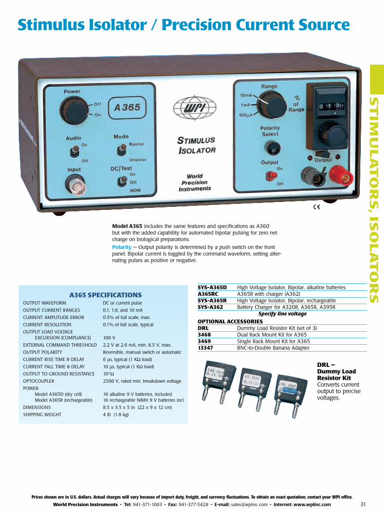
Stimulus Isolator / Precision current Source
DRL — Dummy Load Resistor KitConverts current output to precise voltages.
model a365 includes the same features and specifications as A360 but with the added capability for automated bipolar pulsing for zero net charge on biological preparations.
polarity — Output polarity is determined by a push switch on the front panel. Bipolar current is toggled by the command waveform, setting al ter-nat ing pulses as positive or negative.
A365 SPecIfIcATIOnSOUTPUT WAVEFORM DC or current pulse
OUTPUT CURRENT RANGES 0.1, 1.0, and 10 mA
CURRENT AMPLITUDE ERROR 0.5% of full scale, max.
CURRENT RESOLUTION 0.1% of full scale, typical
OUTPUT LOAD VOLTAGE EXCURSION (COMPLIANCE) 100 V
EXTERNAL COMMAND THRESHOLD 2.2 V at 2.6 mA, min. 8.5 V, max.
OUTPUT POLARITY Reversible, manual switch or automatic
CURRENT RISE TIME & DELAY 6 µs, typical (1 KΩ load)
CURRENT FALL TIME & DELAY 10 µs, typical (1 KΩ load)
OUTPUT TO GROUND RESISTANCE 1012Ω OPTOCOUPLER 2500 V, rated min. breakdown voltage
POWER Model A365D (dry cell) 16 alkaline 9 V batteries, included Model A365R (rechargeable) 16 rechargeable NiMH 9 V batteries incl.
DIMENSIONS 8.5 x 3.5 x 5 in (22 x 9 x 12 cm)
SHIPPING WEIGHT 4 lb (1.8 kg)
Prices shown are in U.S. dollars. Actual charges will vary because of import duty, freight, and currency fluctuations. To obtain an exact quotation, contact your WPI office.
World Precision Instruments • tel: 941-371-1003 • Fax: 941-377-5428 • e-mail: [email protected] • Internet: www.wpiinc.com
SYS-A365D High Voltage Isolator, Bipolar, alkaline batteries A365Rc A365R with charger (A362) SYS-A365R High Voltage Isolator, Bipolar, rechargeable SYS-A362 Battery Charger for A320R, A365R, A395R
Specify line voltage
OPTIOnAL AcceSSORIeSDRL Dummy Load Resistor Kit (set of 3) 3468 Dual Rack Mount Kit for A3653469 Single Rack Mount Kit for A36513347 BNC-to-Double Banana Adapter
32
ST
IMU
LA
TO
RS
, IS
OL
AT
OR
S
A382 SPecIfIcATIOnSPOWER 95-135 V or 220-240 V, 50/60 Hz
DIMENSIONS 8.5 x 3.5 x 5 in (22 x 9 x 12 cm)
SHIPPING WEIGHT 5 lb (2.3 kg)
A385 SPecIfIcATIOnSOUTPUT WAVEFORM DC or current pulse
OUTPUT CURRENT RANGES 1, 10, and 100 mA
CURRENT AMPLITUDE ERROR 0.5% of full scale, max
CURRENT RESOLUTION REPEATABILITY 0.1% of full scale, typical
OUTPUT LOAD VOLTAGE EXCURSION (COMPLIANCE) 36 V
EXTERNAL COMMAND VOLTAGE
THRESHOLD 2.2 V, min
OUTPUT POLARITY Reversible, manual switch, or electronically switched bipolar delivery
CURRENT RISE TIME AND DELAY 6 µs, typical (1 KΩ load)
CURRENT FALL TIME AND DELAY 10 µs, typical (1 KΩ load)
OUTPUT TO GROUND RESISTANCE 1012 Ω
OPTOCOUPLER 2500 V, rated minimum breakdown voltage
POWER Six rechargeable lead-acid batteries (Requires companion charger A382)
DIMENSIONS 8.5 x 3.5 x 5 in. (22 x 9 x 12 cm)
SHIPPING WEIGHT 5 lb (2.3 kg)
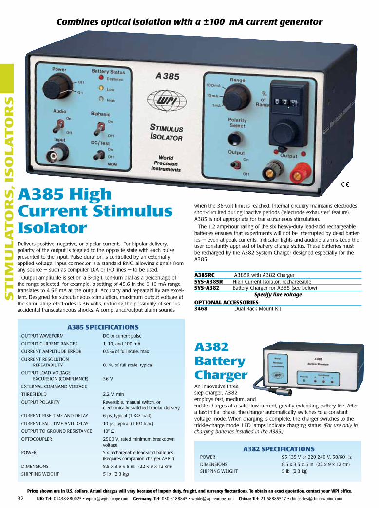
A385 High current Stimulus IsolatorDelivers positive, negative, or bipolar currents. For bipolar delivery, polarity of the output is toggled to the opposite state with each pulse presented to the input. Pulse duration is controlled by an externally applied voltage. In put connector is a standard BNC, allowing signals from any source — such as computer D/A or I/O lines — to be used.
Output amplitude is set on a 3-digit, ten-turn dial as a percentage of the range selected: for example, a setting of 45.6 in the 0-10 mA range trans lates to 4.56 mA at the output. Ac cu ra cy and repeat abil i ty are ex cel-lent. Designed for sub cu ta ne ous stim u la tion, max i mum out put volt age at the stim u lat ing elec trodes is 36 volts, re duc ing the pos si bil i ty of se ri ous ac ci den tal tran s cu ta ne ous shocks. A com pli ance/out put alarm sounds
when the 36-volt lim it is reached. In ter nal cir cuit ry main tains elec trodes short-cir cuit ed dur ing in ac tive pe ri ods (“elec trode ex haust er” fea ture). A385 is not ap pro pri ate for tran s cu ta ne ous stim u la tion.
The 1.2 amp-hour rat ing of the six heavy-duty lead-acid re charge able batteries en sures that ex per i ments will not be in ter rupt ed by dead bat ter-ies — even at peak currents. Indicator lights and audible alarms keep the user constantly apprised of battery charge status. These batteries must be recharged by the A382 Sys tem Charger designed especially for the A385.
Combines optical isolation with a ±100 mA current generator
A382 Battery chargerAn innovative three-step charg er, A382 employs fast, medium, and trickle charg es at a safe, low cur rent, great ly ex tend ing bat tery life. After a fast ini tial phase, the charg er au to mat i cal ly switches to a constant voltage mode. When charg ing is com plete, the charg er switch es to the trickle-charge mode. LED lamps indicate charging status. (For use only in charging batteries in stalled in the A385.)
Prices shown are in U.S. dollars. Actual charges will vary because of import duty, freight, and currency fluctuations. To obtain an exact quotation, contact your WPI office.
UK: Tel: 01438-880025 • [email protected] Germany: Tel: 030-6188845 • [email protected] China: Tel: 21 68885517 • [email protected]
A385Rc A385R with A382 Charger SYS-A385R High Current Isolator, rechargeable SYS-A382 Battery Charger for A385 (see below)
Specify line voltage
OPTIOnAL AcceSSORIeS3468 Dual Rack Mount Kit
33
ST
IMU
LA
TO
RS
, ISO
LA
TO
RS
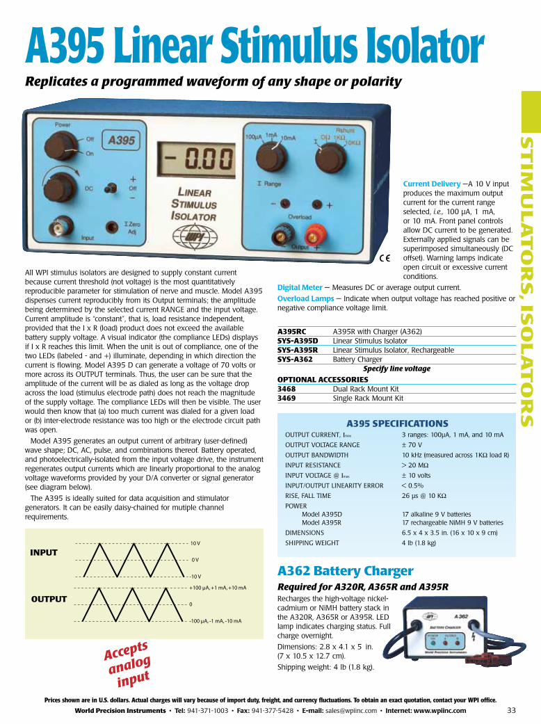
Current Delivery —A 10 V input produces the maximum output current for the current range selected, i.e., 100 µA, 1 mA, or 10 mA. Front panel controls allow DC current to be generated. Externally applied signals can be superimposed si mul ta neous ly (DC offset). Warning lamps indicate open circuit or ex ces sive current conditions.
Digital meter — Measures DC or average output current.
Overload lamps — Indicate when output voltage has reached positive or negative compliance voltage limit.
A362 Battery chargerRequired for A320R, A365R and A395RRecharges the high-voltage nickel-cad mi um or NiMH battery stack in the A320R, A365R or A395R. LED lamp in di cates charg ing status. Full charge over night.
Di men sions: 2.8 x 4.1 x 5 in. (7 x 10.5 x 12.7 cm).
Ship ping weight: 4 lb (1.8 kg).
A395 SPecIfIcATIOnSOUTPUT CURRENT, Imax 3 ranges: 100µA, 1 mA, and 10 mA
OUTPUT VOLTAGE RANGE ± 70 V
OUTPUT BANDWIDTH 10 kHz (measured across 1KΩ load R)
INPUT RESISTANCE > 20 MΩINPUT VOLTAGE @ Imax ± 10 volts
INPUT/OUTPUT LINEARITY ERROR < 0.5%
RISE, FALL TIME 26 µs @ 10 KΩ
POWER Model A395D 17 alkaline 9 V batteries Model A395R 17 rechargeable NiMH 9 V batteries
DIMENSIONS 6.5 x 4 x 3.5 in. (16 x 10 x 9 cm)
SHIPPING WEIGHT 4 lb (1.8 kg)
All WPI stimulus isolators are designed to supply constant current because current threshold (not voltage) is the most quantitatively reproducible parameter for stimulation of nerve and muscle. Model A395 dispenses current reproducibly from its Output terminals; the amplitude being determined by the selected current RANGE and the input voltage. Current amplitude is “constant”, that is, load resistance independent, provided that the I x R (load) product does not exceed the available battery supply voltage. A visual indicator (the compliance LEDs) displays if I x R reaches this limit. When the unit is out of compliance, one of the two LEDs (labeled - and +) illuminate, depending in which direction the current is flowing. Model A395 D can generate a voltage of 70 volts or more across its OUTPUT terminals. Thus, the user can be sure that the amplitude of the current will be as dialed as long as the voltage drop across the load (stimulus electrode path) does not reach the magnitude of the supply voltage. The compliance LEDs will then be visible. The user would then know that (a) too much current was dialed for a given load or (b) inter-electrode resistance was too high or the electrode circuit path was open.
Model A395 generates an output current of arbitrary (user-defined) wave shape; DC, AC, pulse, and combinations thereof. Battery operated, and pho to elec tri cal ly-isolated from the input voltage drive, the instrument regen er ates out put currents which are linearly proportional to the analog voltage wave forms pro vid ed by your D/A con vert er or sig nal generator (see diagram below).
The A395 is ideally suited for data acquisition and stimulator generators. It can be easily daisy-chained for mutiple channel requirements.
10 V
0 V
-10 V
+100 µA, +1 mA, +10 mA
0
-100 µA, -1 mA, -10 mA
Accepts
analog
input
A395 Linear Stimulus IsolatorReplicates a programmed waveform of any shape or polarity
InPUT
OUTPUT
Prices shown are in U.S. dollars. Actual charges will vary because of import duty, freight, and currency fluctuations. To obtain an exact quotation, contact your WPI office.
World Precision Instruments • tel: 941-371-1003 • Fax: 941-377-5428 • e-mail: [email protected] • Internet: www.wpiinc.com
A395Rc A395R with Charger (A362) SYS-A395D Linear Stimulus Isolator SYS-A395R Linear Stimulus Isolator, Rechargeable SYS-A362 Battery Charger
Specify line voltage
OPTIOnAL AcceSSORIeS3468 Dual Rack Mount Kit3469 Single Rack Mount Kit