Simple Model of a Microprocessor System 3D1 ... · 3D1 / Microprocessor Systems I Design and write...
32
3D1 / Microprocessor Systems I A Processing Unit which performs operations on data Memory, which stores: • Data: representing text, images, videos, sensor readings, π, audio, etc. ... • Instructions: Programs are composed of sequences of instructions that control the actions of the processing unit Other peripheral devices • e.g. displays, USB ports, network devices, keyboards, mice, ... 1 Simple Model of a Microprocessor System Memory Memory Programs (instructions) Data Processing Unit e.g. ARM7TDMI BUS + - × ÷ = ? &
Transcript of Simple Model of a Microprocessor System 3D1 ... · 3D1 / Microprocessor Systems I Design and write...

3D1 / Microprocessor Systems I
A Processing Unit which performs operations on data
Memory, which stores: • Data: representing text, images,
videos, sensor readings, π, audio, etc. ...
• Instructions: Programs are composed of sequences of instructions that control the actions of the processing unit
Other peripheral devices
• e.g. displays, USB ports, network devices, keyboards, mice, ...
1
Simple Model of a Microprocessor System Memory
Memory
Programs (instructions) Data
Processing Unit
e.g. ARM7TDMI
BU
S
+ - × ÷ = ? &
3D1 / Microprocessor Systems I
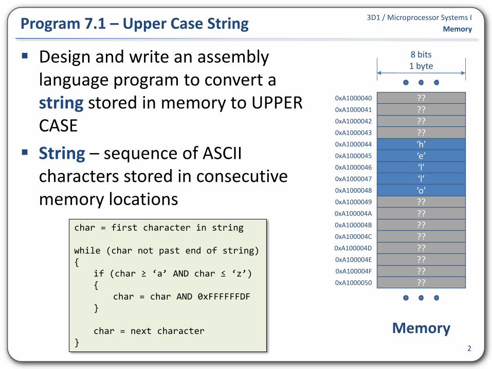
Design and write an assembly language program to convert a string stored in memory to UPPER CASE
String – sequence of ASCII characters stored in consecutive memory locations
2
Program 7.1 – Upper Case String Memory
char = first character in string while (char not past end of string) { if (char ≥ ‘a’ AND char ≤ ‘z’) { char = char AND 0xFFFFFFDF } char = next character }
?? ?? ‘h’ ‘e’ ‘l’
?? ??
0xA1000040
‘l’ ‘o’ ?? ?? ?? ?? ?? ?? ?? ??
8 bits 1 byte
Memory
0xA1000041
0xA1000042
0xA1000043
0xA1000044
0xA1000045
0xA1000046
0xA1000047
0xA1000048
0xA1000049
0xA100004A
0xA100004B
0xA100004C
0xA100004D
0xA100004E
0xA100004F
0xA1000050
3D1 / Microprocessor Systems I
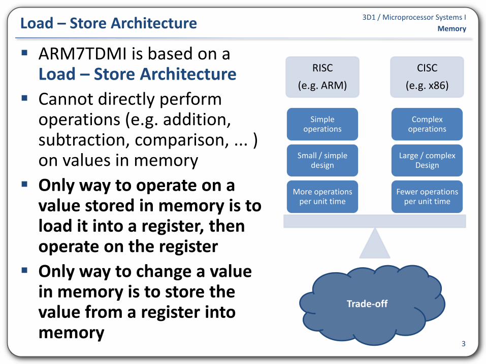
ARM7TDMI is based on a Load – Store Architecture
Cannot directly perform operations (e.g. addition, subtraction, comparison, ... ) on values in memory
Only way to operate on a value stored in memory is to load it into a register, then operate on the register
Only way to change a value in memory is to store the value from a register into memory
3
Load – Store Architecture Memory
RISC
(e.g. ARM)
CISC
(e.g. x86)
Fewer operations per unit time
Large / complex Design
Complex operations
More operations per unit time
Small / simple design
Simple operations
Trade-off

3D1 / Microprocessor Systems I
Refine pseudo-code solution
4
Program 7.1 – Upper Case String Memory
char = first character in string while (char not past end of string) { if (char ≥ ‘a’ AND char ≤ ‘z’) { char = char AND 0xFFFFFFDF } char = next character }
address = address of first character char = Memory.byte [address] while (char not past end of string) { if (char ≥ ‘a’ AND char ≤ ‘z’) { char = char AND 0xFFFFFFDF Memory.byte[address] = char } address = address + 1 char = Memory.byte[address] }
3D1 / Microprocessor Systems I
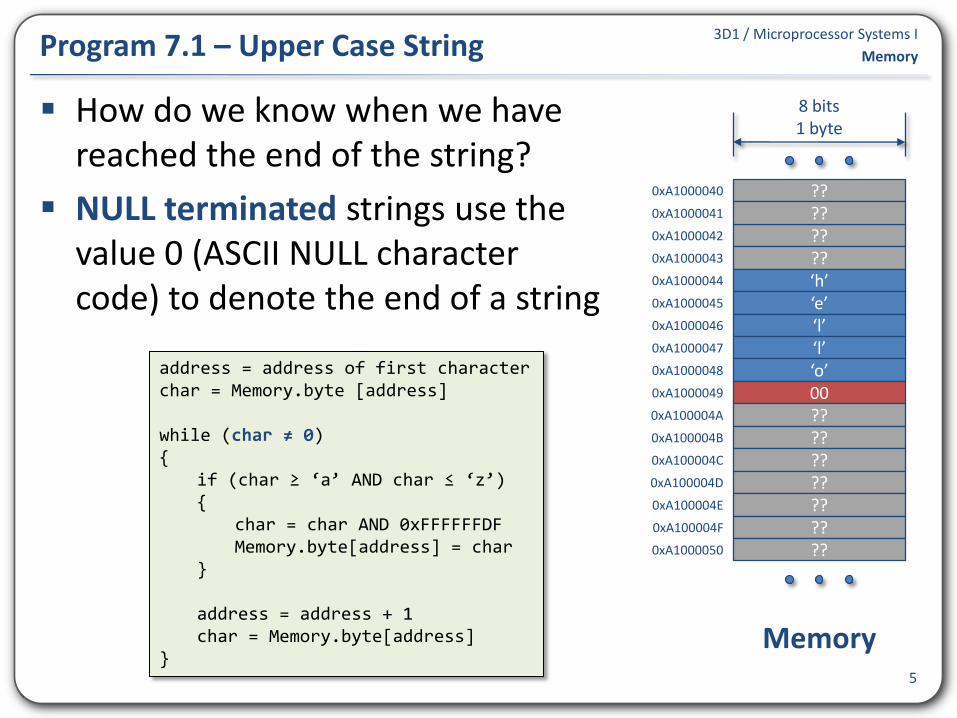
How do we know when we have reached the end of the string?
NULL terminated strings use the value 0 (ASCII NULL character code) to denote the end of a string
5
Program 7.1 – Upper Case String Memory
address = address of first character char = Memory.byte [address] while (char ≠ 0) { if (char ≥ ‘a’ AND char ≤ ‘z’) { char = char AND 0xFFFFFFDF Memory.byte[address] = char } address = address + 1 char = Memory.byte[address] }
?? ?? ‘h’ ‘e’ ‘l’
?? ??
0xA1000040
‘l’ ‘o’ 00 ?? ?? ?? ?? ?? ?? ??
8 bits 1 byte
Memory
0xA1000041
0xA1000042
0xA1000043
0xA1000044
0xA1000045
0xA1000046
0xA1000047
0xA1000048
0xA1000049
0xA100004A
0xA100004B
0xA100004C
0xA100004D
0xA100004E
0xA100004F
0xA1000050

3D1 / Microprocessor Systems I
Load – Rd = Memory.<size>[<address>] • Load a word-, half-word- or byte- <size> value ...
• ... from Memory at a specified <address> ...
• ... into a register
• LDR Rd, <address> load word
• LDRH Rd, <address> load half-word
• LDRB Rd, <address> load byte
Store – Memory.<size>[<address>] = Rd • Store a a word-, half-word- or byte- <size> value ...
• ... from a register ...
• ... into Memory at a specified <address>
• STR Rd, <address> store word
• STRH Rd, <address> store half-word
• STRB Rd, <address> store byte 6
Load / Store Instructions Memory

3D1 / Microprocessor Systems I
Addressing mode – method of specifying the <address> to be used in a load / store operation
Address used is called the effective address
Immediate Offset (with a default zero offset)
• Rn is the base register
Example: load word-size value from memory at address 0xA1000000 into register r1
• r1 = Memory.word[0xA1000000]
7
Addressing Mode [Rn, #0] or [Rn] Memory
LDR r0, =0xA1000000 ; Initialise base register r0 = 0xA1000000 LDR r1, [r0] ; r1 = Memory.word[r0]
<address> = Rn

3D1 / Microprocessor Systems I
Example: Store word-size value from register R1 into memory at address 0xA1000000
• Memory[0xA1000000] = r1
Example: Load byte-size value from register r1 into memory at address 0xA1000000
• r1 = Memory.byte[0xA1000000]
8
Addressing Mode [Rn, #0] or [Rn] Memory
LDR r0, =0xA1000000 ; Initialise base register r0 = 0xA1000000 STR r1, [r0] ; Memory.word[r0] = r1
LDR r0, =0xA1000000 ; Initialise base register r0 = 0xA1000000 LDRB r1, [r0] ; r1 = Memory.byte[r0]
3D1 / Microprocessor Systems I
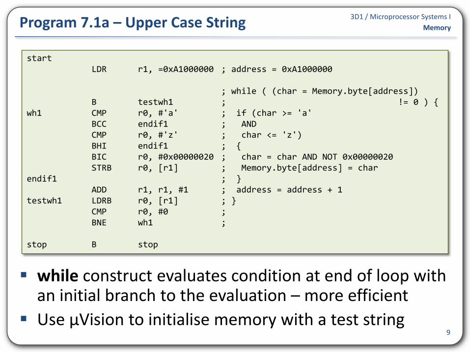
while construct evaluates condition at end of loop with an initial branch to the evaluation – more efficient
Use µVision to initialise memory with a test string 9
Program 7.1a – Upper Case String Memory
start LDR r1, =0xA1000000 ; address = 0xA1000000 ; while ( (char = Memory.byte[address]) B testwh1 ; != 0 ) { wh1 CMP r0, #'a' ; if (char >= 'a' BCC endif1 ; AND CMP r0, #'z' ; char <= 'z') BHI endif1 ; { BIC r0, #0x00000020 ; char = char AND NOT 0x00000020 STRB r0, [r1] ; Memory.byte[address] = char endif1 ; } ADD r1, r1, #1 ; address = address + 1 testwh1 LDRB r0, [r1] ; } CMP r0, #0 ; BNE wh1 ; stop B stop

3D1 / Microprocessor Systems I
Storing an address in a register and subsequently using the register as an operand in a load/store operation is an example of indirection
Indirection is an important concept in Computing generally, not just assembly language programming
We can say r0 “points to” the data in memory at address 0xA1000000
In some contexts (e.g. high-level programming languages such as C or C++) r0 could be referred to as a “pointer” to some data
10
Indirect Addressing Memory
LDR r0, =0xA1000000 ; Initialise base register r1 = 0xA1000000 LDRB r1, [r0] ; r1 = Memory.byte[r0]
3D1 / Microprocessor Systems I
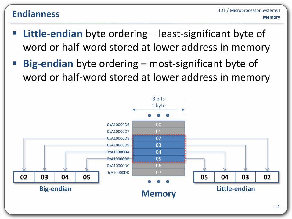
Little-endian byte ordering – least-significant byte of word or half-word stored at lower address in memory
Big-endian byte ordering – most-significant byte of word or half-word stored at lower address in memory
11
Endianness Memory
02 03 04 05 06
00 01
0xA10000D6
07
8 bits 1 byte
Memory
0xA10000D7
0xA10000D8
0xA10000D9
0xA10000DA
0xA10000DB
0xA10000DC
0xA10000DD
05 04 03 02 02 03 04 05
Big-endian Little-endian
3D1 / Microprocessor Systems I
12
Load / Store Bytes, Half-words and Words Memory
? ? ? ? 3 2 0 4 8 5 E B ? ? ? ?
0xA1000042
0xA1000043
0xA1000044
0xA1000045
0xA1000046
0xA1000047
0xA1000048
0xA1000049
3 2 0 0 0 0 0 0
0 7 8 31
3 2 0 4 0 0 0 0
0 15 16 31
3 2 0 4 8 5 EB
0 31
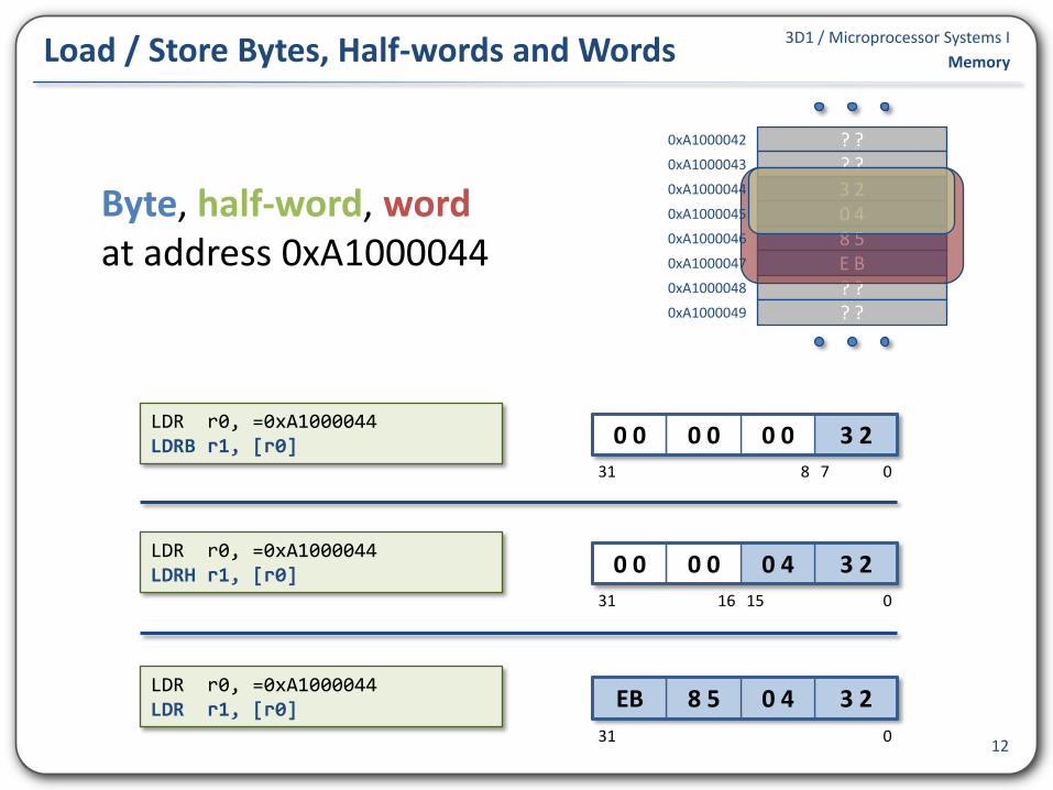
LDR r0, =0xA1000044 LDR r1, [r0]
LDR r0, =0xA1000044 LDRH r1, [r0]
LDR r0, =0xA1000044 LDRB r1, [r0]
Byte, half-word, word at address 0xA1000044
3D1 / Microprocessor Systems I
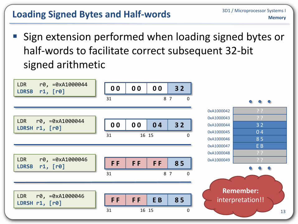
Sign extension performed when loading signed bytes or half-words to facilitate correct subsequent 32-bit signed arithmetic
13
Loading Signed Bytes and Half-words Memory
3 2 0 0 0 0 0 0
0 7 8 31
3 2 0 4 0 0 0 0
0 15 16 31
LDR r0, =0xA1000044 LDRSH r1, [r0]
LDR r0, =0xA1000044 LDRSB r1, [r0]
8 5 F F F F F F
0 7 8 31
8 5 E B F F F F
0 15 16 31
LDR r0, =0xA1000046 LDRSH r1, [r0]
LDR r0, =0xA1000046 LDRSB r1, [r0]
? ? ? ? 3 2 0 4 8 5 E B ? ? ? ?
0xA1000042
0xA1000043
0xA1000044
0xA1000045
0xA1000046
0xA1000047
0xA1000048
0xA1000049
Remember: interpretation!!

3D1 / Microprocessor Systems I
Use the assembler to initialise contents of memory
Example: instead of manually writing a test string into memory, the string can be included with program machine code by the assembler
14
DCD, DCW and DCB Assembler Directives Memory
AREA UpperCaseString, CODE, READONLY IMPORT main EXPORT start start LDR r1, =teststr ; address = 0xA1000000 ... ... ... <rest of program> ... ... ... AREA TestData, DATA, READWRITE teststr DCB "hello",0 ; NULL terminated test string END

3D1 / Microprocessor Systems I
DCD, DCW and DCB are assembler directives. They are not instructions and no machine code is produced.
Other data declaration examples
• 8 word values
• Lotto numbers as byte values
• 2 half-word values
15
DCD, DCW and DCB Assembler Directives Memory
mywords DCD 0x4D1F4004, 0x10301030, 0x141030D4, 0xE4503003 DCD 0x4AB345F0, 0x3049FDEA, 0x0400D4F8, 0x34FD303A
draw DCB 32, 43, 10, 11, 14, 15 bonus DCB 7
values DCW 407, -208

3D1 / Microprocessor Systems I
AREA directive
• Marks the beginning of a section and specifies attributes for the section
• Sections are indivisible sequences of instructions and/or data
• Attribute examples: CODE, READONLY, DATA, READWRITE
• Attributes define how a section is loaded into memory
• Programs must contain at least one CODE section
END directive
• Tells the assembler to stop processing the source file
IMPORT / EXPORT directives
• EXPORT directive exports labels for use by other assemblies
• IMPORT directive allows one assembly to use a label exported by another assembly
16
Other Assembler Directive Memory

3D1 / Microprocessor Systems I
ARM7TDMI expects all memory accesses to be aligned
Examples
See ARM Architecture Reference Manual Section A2.8
Unaligned accesses are permitted but the result is unlikely to be what was intended
Unaligned accesses are supported by later ARM architecture versions
17
Alignment Memory
Word-aligned 0x00000000, 0x00001008, 0xA100000C
Not word-aligned 0x00000001, 0x00001006, 0xA100000F
Half-word aligned 0x0000000, 0x00001002, 0xA100000A
Not half-word aligned 0x00000003, 0x00001001, 0xA100000B

3D1 / Microprocessor Systems I
Load word at address 0xA10000DB
• address is rounded down to nearest aligned address
• loaded value is rotated right 3 bytes before being stored in destination register
18
Unaligned Access Example Memory
1 0 1 0 1 1
31 30 0 1 2 3
1
4
0 1
5 6
0xA10000DB
1 0 1 0 0 0
31 30 2 3
1
4
0 1
5 6
0xA10000D8
02 03 04 05 06
00 01
0xA10000D6
07 08 09
8 bits 1 byte
Memory
0xA10000D7
0xA10000D8
0xA10000D9
0xA10000DA
0xA10000DB
0xA10000DC
0xA10000DD
0xA10000DE
0xA10000DF
0 1
05 02 03 04 02 03 04 05
10 0xA10000E0

3D1 / Microprocessor Systems I
Immediate post-indexed
• After calculating the effective address, the immediate value <offset> is added/subtracted to/from the base register Rn
• Convenient way of updating base register to point to address of next value in memory
Example: load three consecutive half-word values, beginning at address 0xA1001000, into registers r0, r1 and r2
19
Addressing Mode [Rn], #+/-<offset> Memory
<address> = Rn Rn = Rn +/- <12-bit offset>
LDR r0, =0xA1001000 ; Initialise base register r1 = 0xA1001000 LDRH r1, [r0], #2 ; r1 = Memory.halfword[r0], r0 = r0 + 2 LDRH r2, [r0], #2 ; r2 = Memory.halfword[r0], r0 = r0 + 2 LDRH r3, [r0], #2 ; r3 = Memory.halfword[r0], r0 = r0 + 2

3D1 / Microprocessor Systems I
20
Program 7.1b – Upper Case String Memory
AREA UpperCaseString, CODE, READONLY IMPORT main EXPORT start start LDR r1, =teststr ; address = 0xA1000000 ; while ( (char = Memory.byte[address]) B testwh1 ; != 0 ) { wh1 CMP r0, #'a' ; if (char >= 'a' BCC endif1 ; AND CMP r0, #'z' ; char <= 'z') BHI endif1 ; { BIC r0, #0x00000020 ; char = char AND NOT 0x00000020 SUB r2, r1, #1 ; store_address = address - 1 STRB r0, [r2] ; Memory.byte[store_addres] = char endif1 ; } testwh1 LDRB r0, [r1], #1 ; } CMP r0, #0 ; BNE wh1 ; stop B stop AREA TestData, DATA, READWRITE teststr DCB "hello",0 ; NULL terminated test string END
3D1 / Microprocessor Systems I
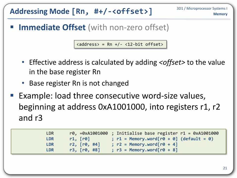
Immediate Offset (with non-zero offset)
• Effective address is calculated by adding <offset> to the value in the base register Rn
• Base register Rn is not changed
Example: load three consecutive word-size values, beginning at address 0xA1001000, into registers r1, r2 and r3
21
Addressing Mode [Rn, #+/-<offset>] Memory
<address> = Rn +/- <12-bit offset>
LDR r0, =0xA1001000 ; Initialise base register r1 = 0xA1001000 LDR r1, [r0] ; r1 = Memory.word[r0 + 0] (default = 0) LDR r2, [r0, #4] ; r2 = Memory.word[r0 + 4] LDR r3, [r0, #8] ; r3 = Memory.word[r0 + 8]

3D1 / Microprocessor Systems I
22
Program 7.1c – Upper Case String Memory
AREA UpperCaseString, CODE, READONLY IMPORT main EXPORT start start LDR r1, =teststr ; address = teststr ; while ( (char = Memory.byte[address]) B testwh1 ; != 0 ) { wh1 CMP r0, #'a' ; if (char >= 'a' BCC endif1 ; AND CMP r0, #'z' ; char <= 'z') BHI endif1 ; { BIC r0, #0x00000020 ; char = char AND NOT 0x00000020 STRB r0, [r1, #-1] ; Memory.byte[addres - 1] = char endif1 ; } testwh1 LDRB r0, [r1], #1 ; } CMP r0, #0 ; BNE wh1 ; stop B stop AREA TestData, DATA, READWRITE teststr DCB "hello",0 ; NULL terminated test string END

3D1 / Microprocessor Systems I
Register offset
• Effective address is calculated by adding offset register Rm to base register Rn
• Rn and Rm are not changed
Example: load three consecutive half-word values, beginning at address 0xA1001000, into registers r1, r2 and r3
23
Addressing Mode [Rn, +/-Rm] Memory
<address> = Rn +/- Rm
LDR r0, =0xA1001000 ; Initialise base register r1 = 0xA1000000 LDR r4, =0 ; Initialise offset register r4 = 0 LDRH r1, [r0, r4] ; r1 = Memory.halfword[r0 + r4] ADD r4, r4, #2 ; r4 = r4 + 2 LDRH r2, [r0, r4] ; r2 = Memory.halfword[r0 + r4] ADD r4, r4, #2 ; r4 = r4 + 2 LDRH r3, [r0, r4] ; r3 = Memory.halfword[r0 + r4]

3D1 / Microprocessor Systems I
24
Program 7.1d – Upper Case String Memory
AREA UpperCaseString, CODE, READONLY IMPORT main EXPORT start start LDR r1, =teststr ; address = teststr LDR r2, =0 ; offset = 0 ; while ( (char = Memory.byte[address B testwh1 ; + offset]) != 0 ) { wh1 CMP r0, #'a' ; if (char >= 'a' BCC endif1 ; AND CMP r0, #'z' ; char <= 'z') BHI endif1 ; { BIC r0, #0x00000020 ; char = char AND NOT 0x00000020 STRB r0, [r1, r2] ; Memory.byte[address + offset] = char endif1 ; } ADD r2, r2, #1 ; offset = offset + 1 testwh1 LDRB r0, [r1, r2] ; } CMP r0, #0 ; BNE wh1 ; stop B stop
3D1 / Microprocessor Systems I
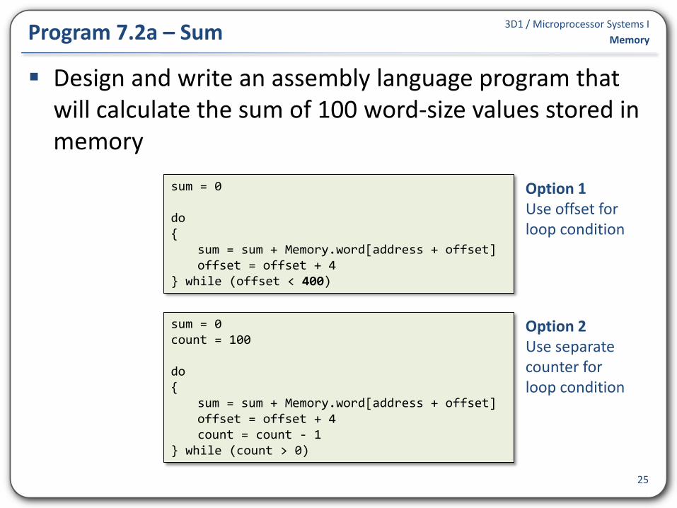
Design and write an assembly language program that will calculate the sum of 100 word-size values stored in memory
25
Program 7.2a – Sum Memory
sum = 0 count = 100 do { sum = sum + Memory.word[address + offset] offset = offset + 4 count = count - 1 } while (count > 0)
sum = 0 do { sum = sum + Memory.word[address + offset] offset = offset + 4 } while (offset < 400)
Option 1 Use offset for loop condition
Option 2 Use separate counter for loop condition
3D1 / Microprocessor Systems I
26
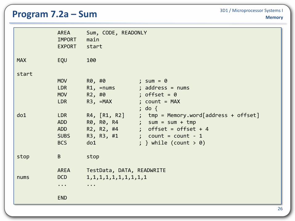
Program 7.2a – Sum Memory
AREA Sum, CODE, READONLY IMPORT main EXPORT start MAX EQU 100 start MOV R0, #0 ; sum = 0 LDR R1, =nums ; address = nums MOV R2, #0 ; offset = 0 LDR R3, =MAX ; count = MAX ; do { do1 LDR R4, [R1, R2] ; tmp = Memory.word[address + offset] ADD R0, R0, R4 ; sum = sum + tmp ADD R2, R2, #4 ; offset = offset + 4 SUBS R3, R3, #1 ; count = count - 1 BCS do1 ; } while (count > 0) stop B stop AREA TestData, DATA, READWRITE nums DCD 1,1,1,1,1,1,1,1,1,1 ... ... END

3D1 / Microprocessor Systems I
Scaled register offset
• Effective address is calculated by adding (offset register Rm shifted by count bits) to base register Rn
• Shift operation can be LSL, LSR, ASR, ROR, RRX
• Rn and Rm are not changed
Example: load three consecutive word values, beginning at address 0xA1001000, into registers r1, r2 and r3
27
Addressing Mode [Rn, +/-Rm, shift #count] Memory
<address> = Rn +/- Rm shift count
LDR r0, =0xA1001000 ; Initialise base register r1 = 0xA1000000 LDR r4, =0 ; Initialise offset register r4 = 0 LDR r1, [r0, r4, LSL #2] ; r1 = Memory.word[r0 + (r4 * 4)] ADD r4, r4, #1 ; r4 = r4 + 1 LDR r2, [r0, r4, LSL #2] ; r2 = Memory.word[r0 + (r4 * 4)] ADD r4, r4, #1 ; r4 = r4 + 1 LDR r3, [r0, r4, LSL #2] ; r3 = Memory.word[r0 + (r4 * 4)]

3D1 / Microprocessor Systems I
28
Program 7.2b – Sum Memory
AREA Sum, CODE, READONLY IMPORT main EXPORT start MAX EQU 100 start MOV R0, #0 ; sum = 0 LDR R1, =nums ; address = nums MOV R2, #0 ; offset = 0 ; do { do1 LDR R3, [R1, R2, LSL #2] ; tmp = Memory.word[address
+ offset * 4] ADD R0, R0, R3 ; sum = sum + tmp ADD R2, R2, #1 ; offset = offset + 1 CMP R2, #MAX ; } while (offset < MAX) BCC do1 ; stop B stop ... ... END

3D1 / Microprocessor Systems I
All modes are available for loads/stored of words and unsigned bytes
A subset of the modes are available for loads/stores of unsigned half-words, signed half-words and signed bytes
Note 12-bit offsets for W, B and 8-bit offsets for H, SH & SB 29
Summary of LDR/STR Addressing Modes Memory
Addressing mode Syntax W, B H, SH, SB Operation
Immediate Offset [<Rn>, #+/-<offset>] address ← Rn +/- offset
Register Offset [<Rn>, +/-<Rm>] address ← Rn +/- Rm
Scaled Register Offset [<Rn, +/-<Rm>, <shift> #<count>] address ← Rn +/- (Rm <shift> <count>)
Immediate Pre-Indexed [<Rn>, #+/-<offset>]!
Rn ← Rn +/- offset
address ← Rn
Register Pre-Indexed [<Rn>, +/-<Rm>]!
Rn ← Rn +/- Rm
address ← Rn
Scaled Register Pre-Indexed [<Rn, +/-<Rm>, <shift> #<count>]!
Rn ← Rn +/- (Rm <shift> <count>)
address ← Rn
Immediate Post-Indexed [<Rn>], #+/-<offset>
address ← Rn
Rn ← Rn +/- offset
Register Post-Indexed [<Rn>], +/-<Rm>
address ← Rn
Rn ← Rn +/- Rm
Scaled Register Post-Indexed [<Rn], +/-<Rm>, <shift> #<count>
address ← Rn
Rn ← Rn +/- (Rm <shift> <count>)

3D1 / Microprocessor Systems I
Design and write an assembly language program that will convert an ASCII representation of a hexadecimal value to a value. The string should be stored as a NULL-terminated string in memory and the converted value should be stored in register r0.
30
Program 7.3 – ASCII string to value Memory
3D1 / Microprocessor Systems I
Design and write an assembly language program to convert a word-size unsigned value stored in memory to its hexadecimal ASCII string representation.
31
Program 7.4 – Value to ASCII String Memory
3D1 / Microprocessor Systems I
Design and write a program that will determine the cardinality of a set of word values stored in memory. The result (cardinality) should be stored in r0.
e.g. if the values stored in memory are ...
4, 9, 3, 4, 7, 9, 12, 10, 4, 7, 3, 12, 5, 5, 7
then the program should store 7 in r0
32
Program 7.5 – Cardinality Memory