
PTFE Lined Piping for use with Corrosive, DIN PN 10/16 ... Pipe DIN.pdf · Reducing Tee 18. Equal...
35
Lined Pipe and Fittings PDS LPF/DIN/01 Iss. 03 This information is for general guidance only, no warranty is given for it’s accuracy and CRP reserve the right to change specifications without notice © CRP www.crp.co.uk Corrosion Resistant Products Ltd. Todmorden Road Littleborough Lancashire United Kingdom OL15 9EG Tel. +44(0) 1706 756 400 Fax. +44(0) 1706 379 567 Email. [email protected] PTFE Lined Piping for use with Corrosive, Hazardous and High Value Processes Van Stone Pipe Spool Manufacture Paste Extrusion PTFE Facility Automated PFA Moulding DIN PN 10/16
Transcript of PTFE Lined Piping for use with Corrosive, DIN PN 10/16 ... Pipe DIN.pdf · Reducing Tee 18. Equal...
Lined Pipe and Fittings PDS LPF/DIN/01 Iss. 03 This information is for general guidance only, no warranty is given for it’s accuracy and CRP reserve the right to change specifications without notice © CRP
Page Page 11 www.crp.co.uk
Corrosion Resistant Products Ltd. Todmorden Road Littleborough Lancashire United Kingdom OL15 9EG
Tel. +44(0) 1706 756 400 Fax. +44(0) 1706 379 567 Email. [email protected]
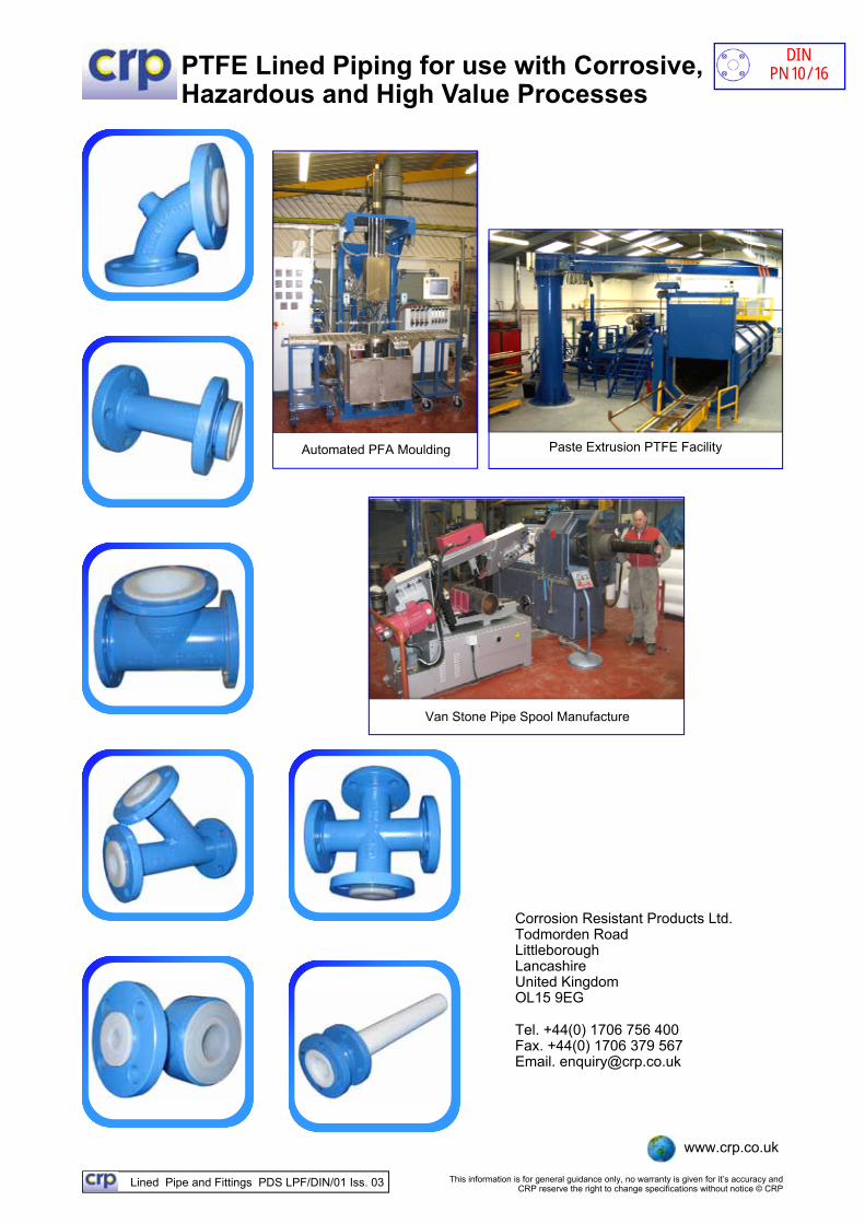
PTFE Lined Piping for use with Corrosive, Hazardous and High Value Processes
Van Stone Pipe Spool Manufacture
Paste Extrusion PTFE Facility Automated PFA Moulding
DIN
PN 10/16
Lined Pipe and Fittings PDS LPF/DIN/01 Iss. 03 This information is for general guidance only, no warranty is given for it’s accuracy and CRP reserve the right to change specifications without notice © CRP
Page Page 22 www.crp.co.uk
Contents
3. Quality System 4. Product Origin 5. Product Certification 6. General Materials of Construction 7. Service Application Ratings 8. Pipe Spools - Fixed / Rotating 9. Pipe Spools - Fixed / Fixed 10. Spacer — Type 1 11. Spacer — Type 2 12. Spacer — Type 3 13. 90 Degree Elbow 14. 90 Degree Long Radius (5D) Elbow 15. 45 Degree Elbow 16. Equal Tee 17. Reducing Tee 18. Equal Tee with Rotating Flanges 19. Instrument Tee 20. Equal Cross 21. Concentric Reducer 22. Eccentric Reducer 23. Reducing Flange 24. Reducing Flange 25. Blank Flange 26. Blanking Spade 27. Solid PTFE Sliding Spectacle Blind 28. Figure 8 Spectacle Blind 29. Toughgask Reusable Gasket 30. CRP Flange Spray Guard Roll 31. Flange Safety Spray Shields 32 FluoroFlow+ Lined Piping 33. Static Dissipating Lined Piping 34. Super Weight Liners For Halogen Service 35. Continuously Lined PTFE Dip Pipe
Page
DIN
PN 10/16
Lined Pipe and Fittings PDS LPF/DIN/01 Iss. 03 This information is for general guidance only, no warranty is given for it’s accuracy and CRP reserve the right to change specifications without notice © CRP
Page Page 33 www.crp.co.uk
Quality System
Corrosion Resistant Products is an ISO 9001:2008 approved company. Originally accredited to BS5750 Part 1 in 1992, CRP maintains this accreditation through a process of continuous third party surveillance with, six monthly, annual and triennial audits taking place. The company was one of the first in the UK to obtain approval to the upgraded version ISO 9001:2008. All of the company’s manufacturing and test procedures fall within this regime.
Design and Test Standards
Products are all manufactured and tested to national and international standards where applicable, with fundamental design qualification having been undertaken via the approval process required to comply with the Pressure Equipment Directive 2014/68/EU.
Qualification Testing: To EDSPIP 53.01C and ASTM F423/ASTM F1545. Rating: Full vacuum up to PN 10/16 pressure rating at 200°C for sizes
up to and including 200NB. Terminations: Fixed flanges fitted off centres. Dimensions: Fitting centreline to face and face to face dimensions are in
accordance with those laid down in DIN 2848 where relevant.
Product Traceability
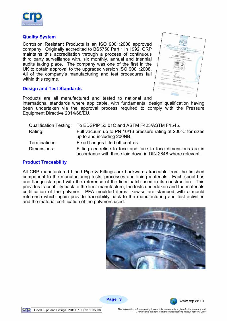
All CRP manufactured Lined Pipe & Fittings are backwards traceable from the finished component to the manufacturing tests, processes and lining materials. Each spool has one flange stamped with the reference of the liner batch used in its construction. This provides traceability back to the liner manufacture, the tests undertaken and the materials certification of the polymer. PFA moulded items likewise are stamped with a mould reference which again provide traceability back to the manufacturing and test activities and the material certification of the polymers used.
Lined Pipe and Fittings PDS LPF/DIN/01 Iss. 03 This information is for general guidance only, no warranty is given for it’s accuracy and CRP reserve the right to change specifications without notice © CRP
Page Page 44 www.crp.co.uk
Product Origin All Corrosion Resistant Products (CRP) manufactured products originate from a single manufacturing source at Littleborough near Manchester, England or produced locally by authorised distributors using CRP liner in accordance with CRP manufacturing and quality assurance procedures. This both clearly establishes the origin and gives a commonality of manufacturing methods and materials – providing consistency of product standards through materials supplied.
Common Product Standards All PTFE pipe spools are manufactured using in-house produced PTFE paste extruded liner, whilst PFA lined fittings use virgin material.
All products are painted with a corrosion resistant two component low VOC, high solids fast curing epoxy primer/finish containing zinc phosphate anti-corrosive pigmentation. Colour RAL 5015 Blue Semi-Gloss. Typical thickness 80 microns.
All products (except type 1 spacers) include suitable venting within the metal structure of the item. Typically one or more 5mm diameter holes in spools and PTFE lined fittings, and the injection boss of PFA moulded fittings.
When Vent Extensions are required, a 10mm high G 1/4 internally threaded boss is welded to pipe spools. For moulded fittings the injection boss is drilled and tapped with an appropriate female taper thread. A 65mm long vent extension is then supplied to fit to this, to provide a standard 75mm vent extension.
Special requirements As part of the supply CRP can provide alternative special paint finishes, stainless steel spools & fittings, BS or ASME flanges, the use of static dissipating polymers, special low temperature service requirements, non-standard face to face dimensions, rotating flanges and the creation of special components for the reduction of flanges or to assist in tight access areas.
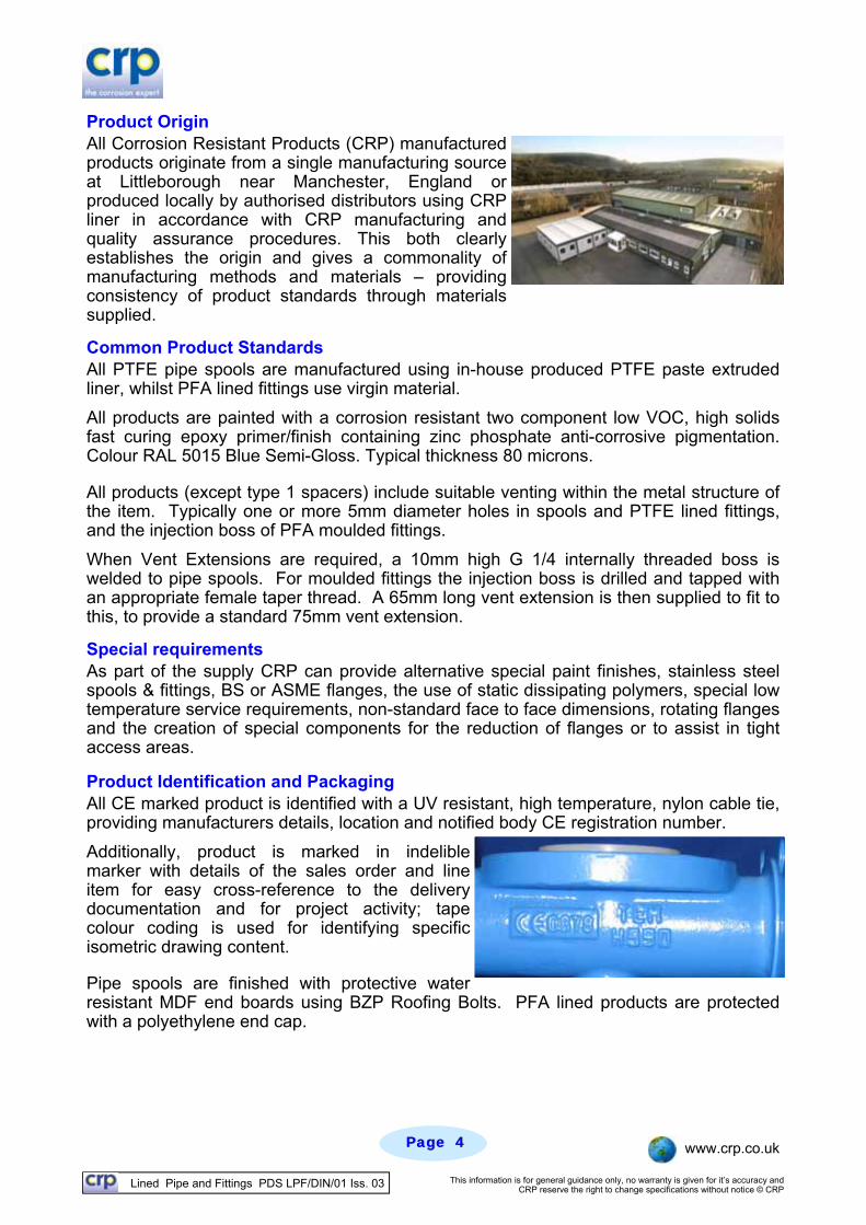
Product Identification and Packaging All CE marked product is identified with a UV resistant, high temperature, nylon cable tie, providing manufacturers details, location and notified body CE registration number.
Additionally, product is marked in indelible marker with details of the sales order and line item for easy cross-reference to the delivery documentation and for project activity; tape colour coding is used for identifying specific isometric drawing content.
Pipe spools are finished with protective water resistant MDF end boards using BZP Roofing Bolts. PFA lined products are protected with a polyethylene end cap.
Lined Pipe and Fittings PDS LPF/DIN/01 Iss. 03 This information is for general guidance only, no warranty is given for it’s accuracy and CRP reserve the right to change specifications without notice © CRP
Page Page 55 www.crp.co.uk
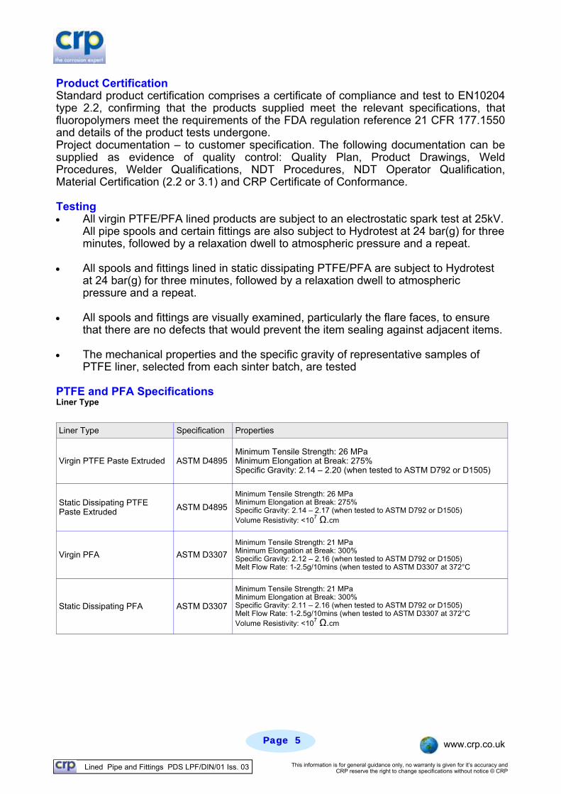
Product Certification Standard product certification comprises a certificate of compliance and test to EN10204 type 2.2, confirming that the products supplied meet the relevant specifications, that fluoropolymers meet the requirements of the FDA regulation reference 21 CFR 177.1550 and details of the product tests undergone. Project documentation – to customer specification. The following documentation can be supplied as evidence of quality control: Quality Plan, Product Drawings, Weld Procedures, Welder Qualifications, NDT Procedures, NDT Operator Qualification, Material Certification (2.2 or 3.1) and CRP Certificate of Conformance. Testing All virgin PTFE/PFA lined products are subject to an electrostatic spark test at 25kV.
All pipe spools and certain fittings are also subject to Hydrotest at 24 bar(g) for three minutes, followed by a relaxation dwell to atmospheric pressure and a repeat.
All spools and fittings lined in static dissipating PTFE/PFA are subject to Hydrotest
at 24 bar(g) for three minutes, followed by a relaxation dwell to atmospheric pressure and a repeat.
All spools and fittings are visually examined, particularly the flare faces, to ensure
that there are no defects that would prevent the item sealing against adjacent items. The mechanical properties and the specific gravity of representative samples of
PTFE liner, selected from each sinter batch, are tested PTFE and PFA Specifications Liner Type
Liner Type Specification Properties
Virgin PTFE Paste Extruded ASTM D4895 Minimum Tensile Strength: 26 MPa Minimum Elongation at Break: 275% Specific Gravity: 2.14 – 2.20 (when tested to ASTM D792 or D1505)
Static Dissipating PTFE Paste Extruded ASTM D4895
Minimum Tensile Strength: 26 MPa Minimum Elongation at Break: 275% Specific Gravity: 2.14 – 2.17 (when tested to ASTM D792 or D1505) Volume Resistivity: <107 Ω.cm
Virgin PFA ASTM D3307
Minimum Tensile Strength: 21 MPa Minimum Elongation at Break: 300% Specific Gravity: 2.12 – 2.16 (when tested to ASTM D792 or D1505) Melt Flow Rate: 1-2.5g/10mins (when tested to ASTM D3307 at 372°C
Static Dissipating PFA ASTM D3307
Minimum Tensile Strength: 21 MPa Minimum Elongation at Break: 300% Specific Gravity: 2.11 – 2.16 (when tested to ASTM D792 or D1505) Melt Flow Rate: 1-2.5g/10mins (when tested to ASTM D3307 at 372°C Volume Resistivity: <107 Ω.cm
Lined Pipe and Fittings PDS LPF/DIN/01 Iss. 03 This information is for general guidance only, no warranty is given for it’s accuracy and CRP reserve the right to change specifications without notice © CRP
Page Page 66 www.crp.co.uk
Materials Specification
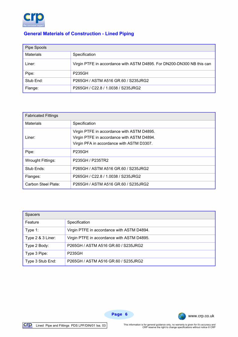
Liner: Virgin PTFE in accordance with ASTM D4895. For DN200-DN300 NB this can
Pipe: P235GH
Stub End: P265GH / ASTM A516 GR.60 / S235JRG2
Flange: P265GH / C22.8 / 1.0038 / S235JRG2
Pipe Spools
Materials Specification
Liner:
Virgin PTFE in accordance with ASTM D4895.
Virgin PTFE in accordance with ASTM D4894.
Virgin PFA in accordance with ASTM D3307.
Pipe: P235GH
Stub Ends: P265GH / ASTM A516 GR.60 / S235JRG2
Flanges: P265GH / C22.8 / 1.0038 / S235JRG2
Fabricated Fittings
Wrought Fittings: P235GH / P235TR2
Carbon Steel Plate: P265GH / ASTM A516 GR.60 / S235JRG2
Spacers
Feature Specification
Type 1: Virgin PTFE in accordance with ASTM D4894.
Type 2 & 3 Liner: Virgin PTFE in accordance with ASTM D4895.
Type 2 Body: P265GH / ASTM A516 GR.60 / S235JRG2
Type 3 Pipe: P235GH
Type 3 Stub End: P265GH / ASTM A516 GR.60 / S235JRG2
General Materials of Construction - Lined Piping
Lined Pipe and Fittings PDS LPF/DIN/01 Iss. 03 This information is for general guidance only, no warranty is given for it’s accuracy and CRP reserve the right to change specifications without notice © CRP
Page Page 77 www.crp.co.uk
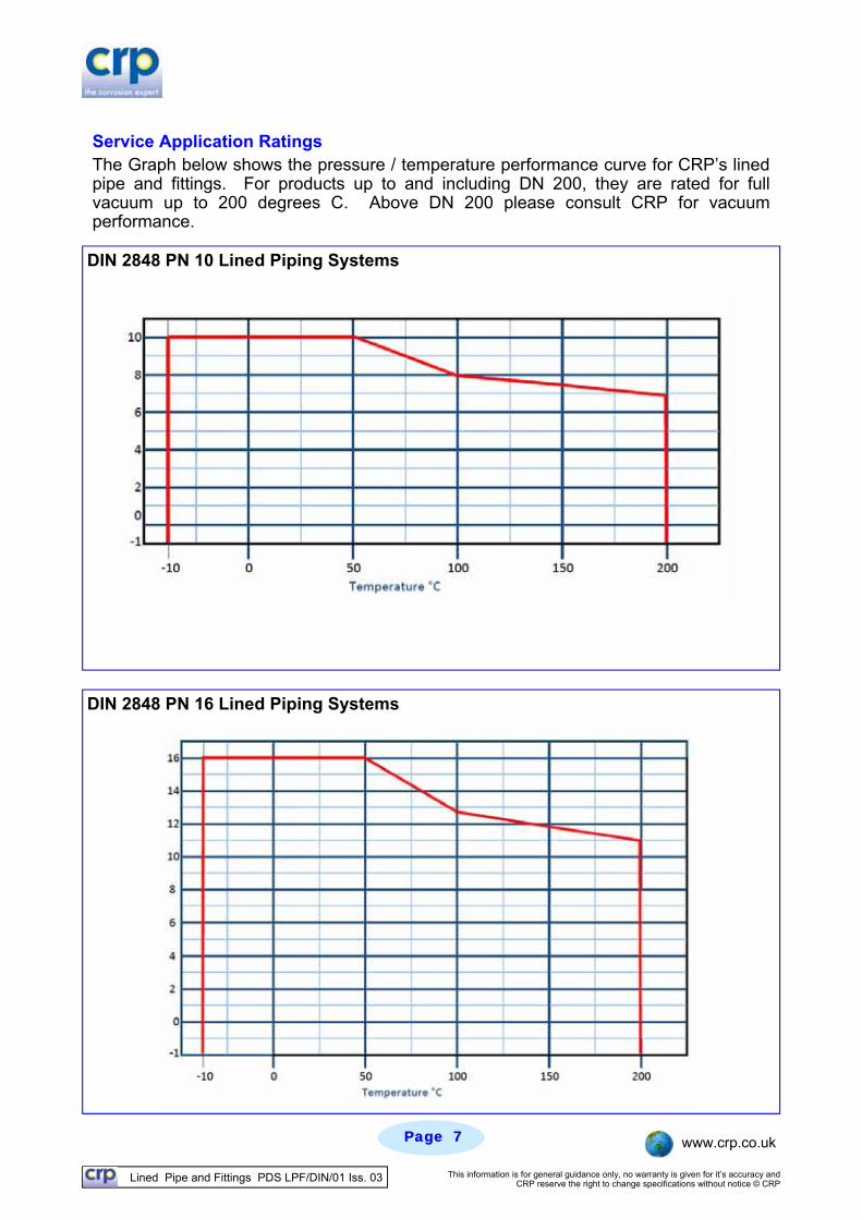
DIN 2848 PN 16 Lined Piping Systems
DIN 2848 PN 10 Lined Piping Systems
Service Application Ratings The Graph below shows the pressure / temperature performance curve for CRP’s lined pipe and fittings. For products up to and including DN 200, they are rated for full vacuum up to 200 degrees C. Above DN 200 please consult CRP for vacuum performance.
Lined Pipe and Fittings PDS LPF/DIN/01 Iss. 03 This information is for general guidance only, no warranty is given for it’s accuracy and CRP reserve the right to change specifications without notice © CRP
Page Page 88 www.crp.co.uk
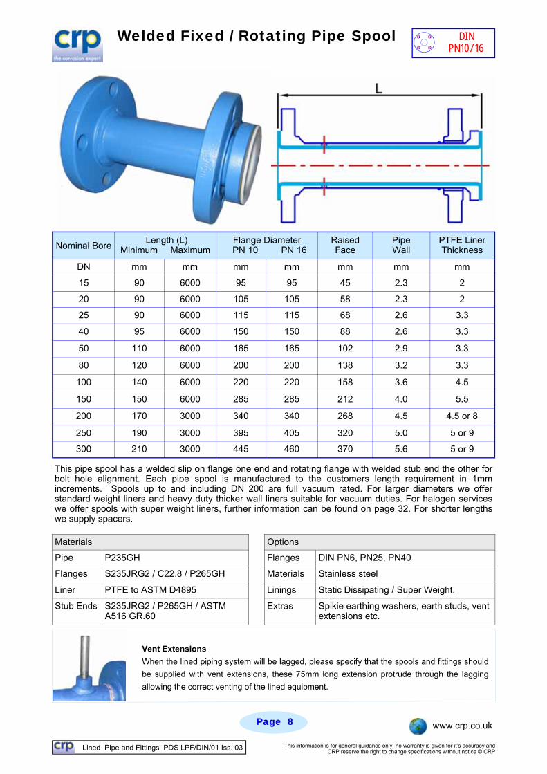
Welded Fixed / Rotating Pipe Spool
Nominal Bore Length (L)
Minimum Maximum Flange Diameter
PN 10 PN 16 Raised Face
Pipe Wall
PTFE Liner Thickness
DN mm mm mm mm mm mm mm
15 90 6000 95 95 45 2.3 2
20 90 6000 105 105 58 2.3 2
25 90 6000 115 115 68 2.6 3.3
40 95 6000 150 150 88 2.6 3.3
50 110 6000 165 165 102 2.9 3.3
80 120 6000 200 200 138 3.2 3.3
100 140 6000 220 220 158 3.6 4.5
150 150 6000 285 285 212 4.0 5.5
200 170 3000 340 340 268 4.5 4.5 or 8
250 190 3000 395 405 320 5.0 5 or 9
300 210 3000 445 460 370 5.6 5 or 9
This pipe spool has a welded slip on flange one end and rotating flange with welded stub end the other for bolt hole alignment. Each pipe spool is manufactured to the customers length requirement in 1mm increments. Spools up to and including DN 200 are full vacuum rated. For larger diameters we offer standard weight liners and heavy duty thicker wall liners suitable for vacuum duties. For halogen services we offer spools with super weight liners, further information can be found on page 32. For shorter lengths we supply spacers.
Materials
Pipe P235GH Flanges DIN PN6, PN25, PN40
Flanges S235JRG2 / C22.8 / P265GH Materials Stainless steel
Liner PTFE to ASTM D4895 Linings Static Dissipating / Super Weight.
Stub Ends S235JRG2 / P265GH / ASTM A516 GR.60
Extras Spikie earthing washers, earth studs, vent extensions etc.
Options
Vent Extensions
When the lined piping system will be lagged, please specify that the spools and fittings should
be supplied with vent extensions, these 75mm long extension protrude through the lagging
allowing the correct venting of the lined equipment.
DIN PN10/16
Lined Pipe and Fittings PDS LPF/DIN/01 Iss. 03 This information is for general guidance only, no warranty is given for it’s accuracy and CRP reserve the right to change specifications without notice © CRP
Page Page 99 www.crp.co.uk
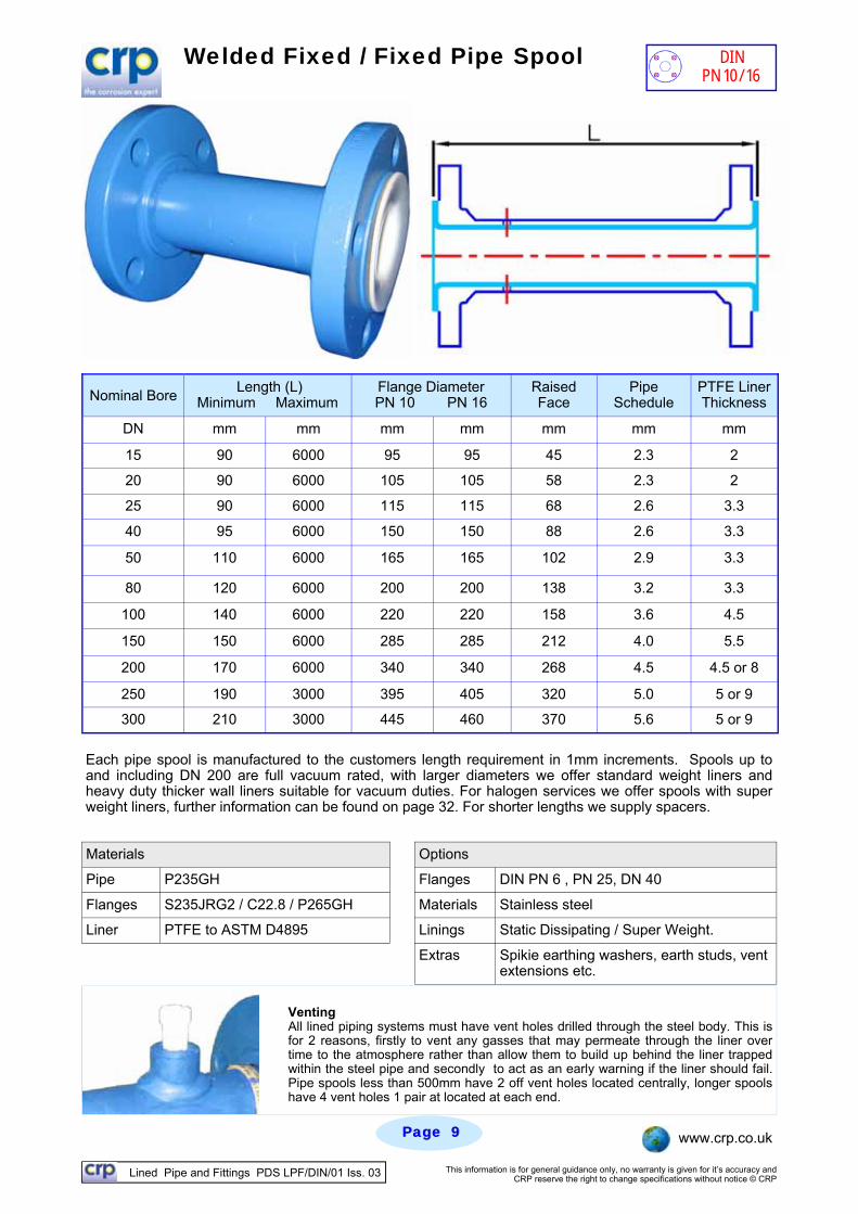
Welded Fixed / Fixed Pipe Spool
Nominal Bore Length (L)
Minimum Maximum Flange Diameter PN 10 PN 16
Raised Face
Pipe Schedule
PTFE Liner Thickness
DN mm mm mm mm mm mm mm
15 90 6000 95 95 45 2.3 2
20 90 6000 105 105 58 2.3 2
25 90 6000 115 115 68 2.6 3.3
40 95 6000 150 150 88 2.6 3.3
50 110 6000 165 165 102 2.9 3.3
80 120 6000 200 200 138 3.2 3.3
100 140 6000 220 220 158 3.6 4.5
150 150 6000 285 285 212 4.0 5.5
200 170 6000 340 340 268 4.5 4.5 or 8
250 190 3000 395 405 320 5.0 5 or 9
300 210 3000 445 460 370 5.6 5 or 9
Each pipe spool is manufactured to the customers length requirement in 1mm increments. Spools up to and including DN 200 are full vacuum rated, with larger diameters we offer standard weight liners and heavy duty thicker wall liners suitable for vacuum duties. For halogen services we offer spools with super weight liners, further information can be found on page 32. For shorter lengths we supply spacers.
Venting All lined piping systems must have vent holes drilled through the steel body. This is for 2 reasons, firstly to vent any gasses that may permeate through the liner over time to the atmosphere rather than allow them to build up behind the liner trapped within the steel pipe and secondly to act as an early warning if the liner should fail. Pipe spools less than 500mm have 2 off vent holes located centrally, longer spools have 4 vent holes 1 pair at located at each end.
Materials
Pipe P235GH Flanges DIN PN 6 , PN 25, DN 40
Flanges S235JRG2 / C22.8 / P265GH Materials Stainless steel
Liner PTFE to ASTM D4895 Linings Static Dissipating / Super Weight.
Extras Spikie earthing washers, earth studs, vent extensions etc.
Options
DIN PN 10/16
Lined Pipe and Fittings PDS LPF/DIN/01 Iss. 03 This information is for general guidance only, no warranty is given for it’s accuracy and CRP reserve the right to change specifications without notice © CRP
Page Page 1010 www.crp.co.uk
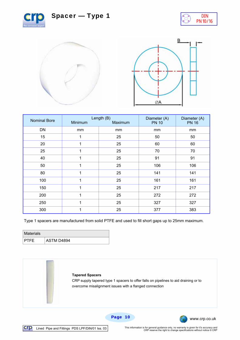
Spacer — Type 1
Type 1 spacers are manufactured from solid PTFE and used to fill short gaps up to 25mm maximum.
Tapered Spacers
CRP supply tapered type 1 spacers to offer falls on pipelines to aid draining or to
overcome misalignment issues with a flanged connection
Materials
PTFE ASTM D4894
Nominal Bore Length (B)
Minimum Maximum Diameter (A)
PN 10
DN mm mm mm
20 1 25 60
25 1 25 70
40 1 25 91
50 1 25 106
80 1 25 141
100 1 25 161
150 1 25 217
200 1 25 272
250 1 25 327
300 1 25 377
15 1 25 50
Diameter (A) PN 16
mm
50
60
70
91
106
141
161
217
272
327
383
DIN PN 10/16
Lined Pipe and Fittings PDS LPF/DIN/01 Iss. 03 This information is for general guidance only, no warranty is given for it’s accuracy and CRP reserve the right to change specifications without notice © CRP
Page Page 1111 www.crp.co.uk
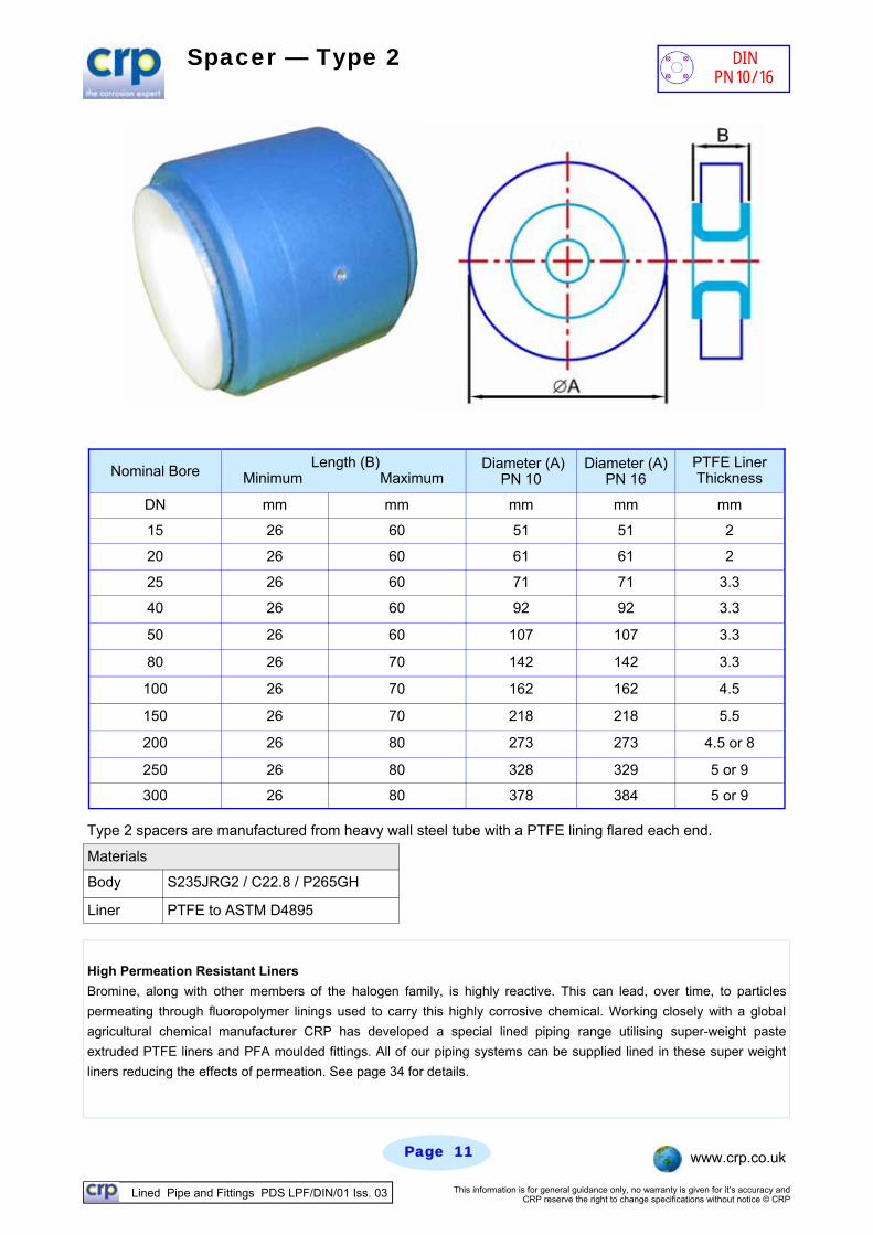
Spacer — Type 2
Type 2 spacers are manufactured from heavy wall steel tube with a PTFE lining flared each end.
High Permeation Resistant Liners
Bromine, along with other members of the halogen family, is highly reactive. This can lead, over time, to particles
permeating through fluoropolymer linings used to carry this highly corrosive chemical. Working closely with a global
agricultural chemical manufacturer CRP has developed a special lined piping range utilising super-weight paste
extruded PTFE liners and PFA moulded fittings. All of our piping systems can be supplied lined in these super weight
liners reducing the effects of permeation. See page 34 for details.
Nominal Bore Length (B)
Minimum Maximum Diameter (A)
PN 10 PTFE Liner Thickness
DN mm mm mm mm
20 26 60 61 2
25 26 60 71 3.3
40 26 60 92 3.3
50 26 60 107 3.3
80 26 70 142 3.3
100 26 70 162 4.5
150 26 70 218 5.5
200 26 80 273 4.5 or 8
250 26 80 328 5 or 9
300 26 80 378 5 or 9
15 26 60 51 2
Diameter (A) PN 16
mm
51
61
71
92
107
142
162
218
273
329
384
Materials
Body S235JRG2 / C22.8 / P265GH
Liner PTFE to ASTM D4895
DIN PN 10/16
Lined Pipe and Fittings PDS LPF/DIN/01 Iss. 03 This information is for general guidance only, no warranty is given for it’s accuracy and CRP reserve the right to change specifications without notice © CRP
Page Page 1212 www.crp.co.uk
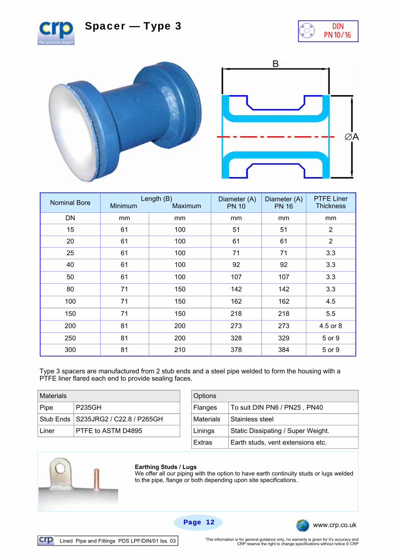
Spacer — Type 3
Type 3 spacers are manufactured from 2 stub ends and a steel pipe welded to form the housing with a PTFE liner flared each end to provide sealing faces.
Materials
Pipe P235GH Flanges To suit DIN PN6 / PN25 , PN40
Stub Ends S235JRG2 / C22.8 / P265GH Materials Stainless steel
Liner PTFE to ASTM D4895 Linings Static Dissipating / Super Weight.
Extras Earth studs, vent extensions etc.
Options
Earthing Studs / Lugs We offer all our piping with the option to have earth continuity studs or lugs welded to the pipe, flange or both depending upon site specifications.
DIN PN 10/16
Nominal Bore Length (B)
Minimum Maximum Diameter (A)
PN 10 PTFE Liner Thickness
DN mm mm mm mm
20 61 100 61 2
25 61 100 71 3.3
40 61 100 92 3.3
50 61 100 107 3.3
80 71 150 142 3.3
100 71 150 162 4.5
150 71 150 218 5.5
200 81 200 273 4.5 or 8
250 81 200 328 5 or 9
300 81 210 378 5 or 9
15 61 100 51 2
Diameter (A) PN 16
mm
51
61
71
92
107
142
162
218
273
329
384
Lined Pipe and Fittings PDS LPF/DIN/01 Iss. 03 This information is for general guidance only, no warranty is given for it’s accuracy and CRP reserve the right to change specifications without notice © CRP
Page Page 1313 www.crp.co.uk
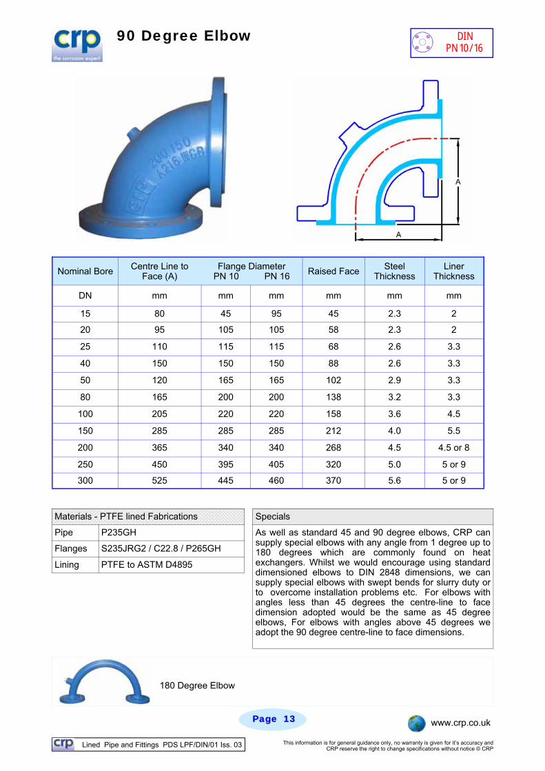
90 Degree Elbow
Materials - PTFE lined Fabrications Specials
Pipe P235GH
Flanges S235JRG2 / C22.8 / P265GH
Lining PTFE to ASTM D4895
As well as standard 45 and 90 degree elbows, CRP can supply special elbows with any angle from 1 degree up to 180 degrees which are commonly found on heat exchangers. Whilst we would encourage using standard dimensioned elbows to DIN 2848 dimensions, we can supply special elbows with swept bends for slurry duty or to overcome installation problems etc. For elbows with angles less than 45 degrees the centre-line to face dimension adopted would be the same as 45 degree elbows, For elbows with angles above 45 degrees we adopt the 90 degree centre-line to face dimensions.
Nominal Bore Centre Line to Face (A)
Flange Diameter PN 10 PN 16 Raised Face Steel
Thickness Liner
Thickness
DN mm mm mm mm mm mm
15 80 45 95 45 2.3 2
20 95 105 105 58 2.3 2
25 110 115 115 68 2.6 3.3
40 150 150 150 88 2.6 3.3
50 120 165 165 102 2.9 3.3
80 165 200 200 138 3.2 3.3
100 205 220 220 158 3.6 4.5
150 285 285 285 212 4.0 5.5
200 365 340 340 268 4.5 4.5 or 8
250 450 395 405 320 5.0 5 or 9
300 525 445 460 370 5.6 5 or 9
180 Degree Elbow
DIN PN 10/16
Lined Pipe and Fittings PDS LPF/DIN/01 Iss. 03 This information is for general guidance only, no warranty is given for it’s accuracy and CRP reserve the right to change specifications without notice © CRP
Page Page 1414 www.crp.co.uk
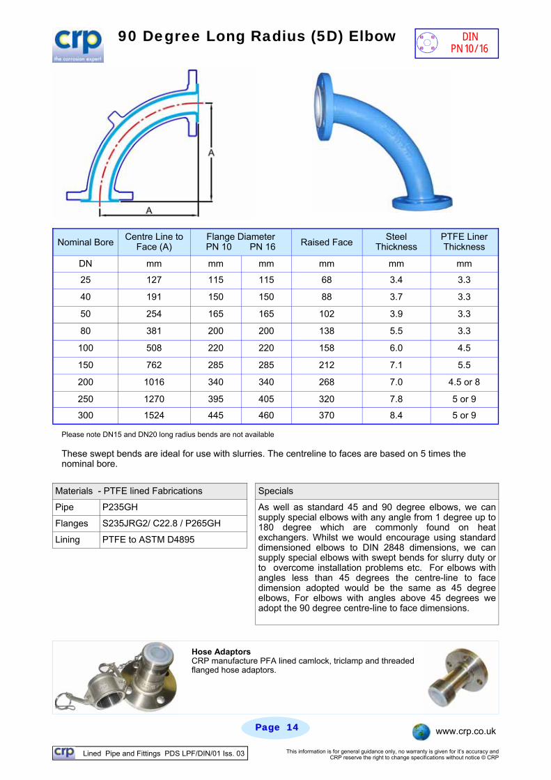
Please note DN15 and DN20 long radius bends are not available These swept bends are ideal for use with slurries. The centreline to faces are based on 5 times the nominal bore.
90 Degree Long Radius (5D) Elbow
Materials - PTFE lined Fabrications Specials
Pipe P235GH
Flanges S235JRG2/ C22.8 / P265GH
Lining PTFE to ASTM D4895
As well as standard 45 and 90 degree elbows, we can supply special elbows with any angle from 1 degree up to 180 degree which are commonly found on heat exchangers. Whilst we would encourage using standard dimensioned elbows to DIN 2848 dimensions, we can supply special elbows with swept bends for slurry duty or to overcome installation problems etc. For elbows with angles less than 45 degrees the centre-line to face dimension adopted would be the same as 45 degree elbows, For elbows with angles above 45 degrees we adopt the 90 degree centre-line to face dimensions.
Nominal Bore Centre Line to
Face (A) Raised Face Steel
Thickness PTFE Liner Thickness
DN mm mm mm mm mm mm
25 127 115 115 68 3.4 3.3
40 191 150 150 88 3.7 3.3
50 254 165 165 102 3.9 3.3
80 381 200 200 138 5.5 3.3
100 508 220 220 158 6.0 4.5
150 762 285 285 212 7.1 5.5
200 1016 340 340 268 7.0 4.5 or 8
250 1270 395 405 320 7.8 5 or 9
300 1524 445 460 370 8.4 5 or 9
Flange Diameter PN 10 PN 16
Hose Adaptors CRP manufacture PFA lined camlock, triclamp and threaded flanged hose adaptors.
DIN PN 10/16
Lined Pipe and Fittings PDS LPF/DIN/01 Iss. 03 This information is for general guidance only, no warranty is given for it’s accuracy and CRP reserve the right to change specifications without notice © CRP
Page Page 1515 www.crp.co.uk
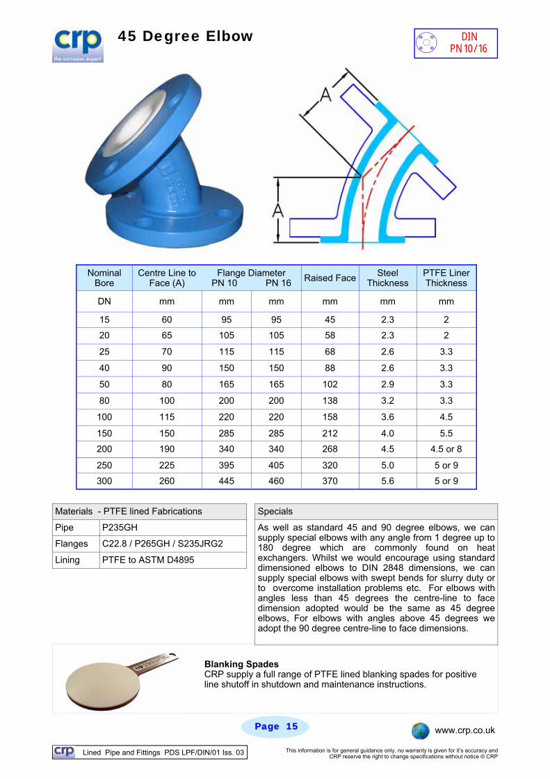
45 Degree Elbow
Nominal Bore
Centre Line to Face (A)
Flange Diameter PN 10 PN 16 Raised Face Steel
Thickness PTFE Liner Thickness
DN mm mm mm mm mm mm
15 60 95 95 45 2.3 2
20 65 105 105 58 2.3 2
25 70 115 115 68 2.6 3.3
40 90 150 150 88 2.6 3.3
50 80 165 165 102 2.9 3.3
80 100 200 200 138 3.2 3.3
100 115 220 220 158 3.6 4.5
150 150 285 285 212 4.0 5.5
200 190 340 340 268 4.5 4.5 or 8
250 225 395 405 320 5.0 5 or 9
300 260 445 460 370 5.6 5 or 9
Blanking Spades CRP supply a full range of PTFE lined blanking spades for positive line shutoff in shutdown and maintenance instructions.
DIN PN 10/16
Materials - PTFE lined Fabrications Specials
Pipe P235GH
Flanges C22.8 / P265GH / S235JRG2
Lining PTFE to ASTM D4895
As well as standard 45 and 90 degree elbows, we can supply special elbows with any angle from 1 degree up to 180 degree which are commonly found on heat exchangers. Whilst we would encourage using standard dimensioned elbows to DIN 2848 dimensions, we can supply special elbows with swept bends for slurry duty or to overcome installation problems etc. For elbows with angles less than 45 degrees the centre-line to face dimension adopted would be the same as 45 degree elbows, For elbows with angles above 45 degrees we adopt the 90 degree centre-line to face dimensions.
Lined Pipe and Fittings PDS LPF/DIN/01 Iss. 03 This information is for general guidance only, no warranty is given for it’s accuracy and CRP reserve the right to change specifications without notice © CRP
Page Page 1616 www.crp.co.uk
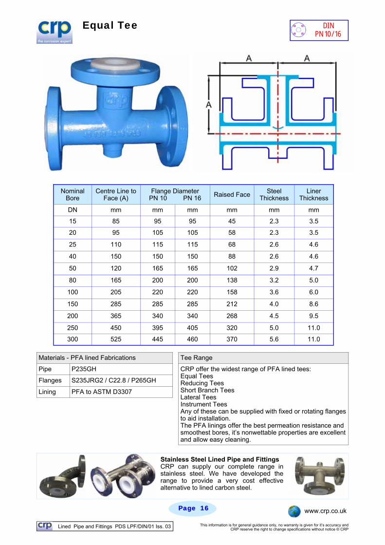
Equal Tee
Materials - PFA lined Fabrications Tee Range
Pipe P235GH
Flanges S235JRG2 / C22.8 / P265GH
Lining PFA to ASTM D3307
CRP offer the widest range of PFA lined tees: Equal Tees Reducing Tees Short Branch Tees Lateral Tees Instrument Tees Any of these can be supplied with fixed or rotating flanges to aid installation. The PFA linings offer the best permeation resistance and smoothest bores, it’s nonwettable properties are excellent and allow easy cleaning.
Nominal Bore
Centre Line to Face (A)
Flange Diameter PN 10 PN 16 Raised Face Steel
Thickness Liner
Thickness
DN mm mm mm mm mm mm
15 85 95 95 45 2.3 3.5
20 95 105 105 58 2.3 3.5
25 110 115 115 68 2.6 4.6
40 150 150 150 88 2.6 4.6
50 120 165 165 102 2.9 4.7
80 165 200 200 138 3.2 5.0
100 205 220 220 158 3.6 6.0
150 285 285 285 212 4.0 8.6
200 365 340 340 268 4.5 9.5
250 450 395 405 320 5.0 11.0
300 525 445 460 370 5.6 11.0
Stainless Steel Lined Pipe and Fittings CRP can supply our complete range in stainless steel. We have developed the range to provide a very cost effective alternative to lined carbon steel.
DIN PN 10/16
Lined Pipe and Fittings PDS LPF/DIN/01 Iss. 03 This information is for general guidance only, no warranty is given for it’s accuracy and CRP reserve the right to change specifications without notice © CRP
Page Page 1717 www.crp.co.uk
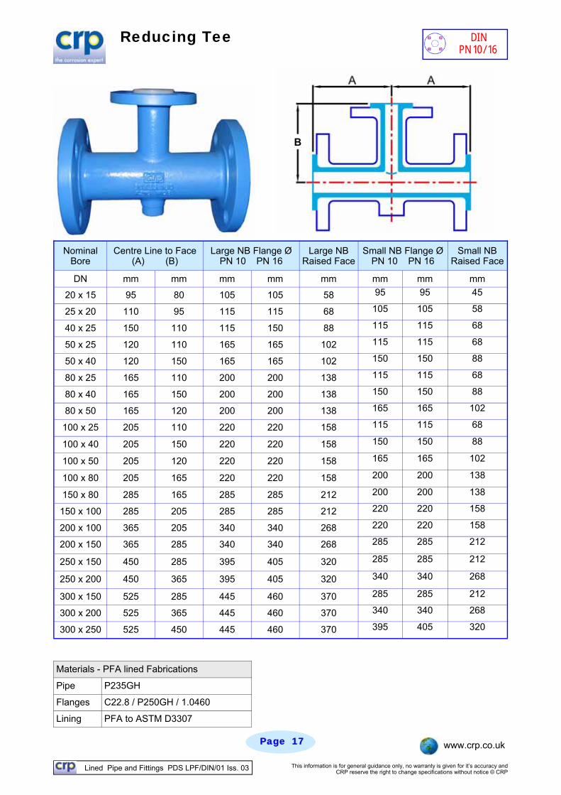
Reducing Tee
Materials - PFA lined Fabrications
Pipe P235GH
Flanges C22.8 / P250GH / 1.0460
Lining PFA to ASTM D3307
Nominal Bore
Centre Line to Face (A) (B)
Large NB Flange Ø PN 10 PN 16
Large NB Raised Face
Small NB Flange Ø PN 10 PN 16
Small NB Raised Face
DN mm mm mm mm mm mm mm mm
20 x 15 95 80 105 105 58 95 95 45
25 x 20 110 95 115 115 68 105 105 58
40 x 25 150 110 115 150 88 115 115 68
50 x 25 120 110 165 165 102 115 115 68
50 x 40 120 150 165 165 102 150 150 88
80 x 25 165 110 200 200 138 115 115 68
80 x 40 165 150 200 200 138 150 150 88
80 x 50 165 120 200 200 138 165 165 102
100 x 25 205 110 220 220 158 115 115 68
100 x 40 205 150 220 220 158 150 150 88
100 x 50 205 120 220 220 158 165 165 102
100 x 80 205 165 220 220 158 200 200 138
150 x 80 285 165 285 285 212 200 200 138
150 x 100 285 205 285 285 212 220 220 158
200 x 100 365 205 340 340 268 220 220 158
200 x 150 365 285 340 340 268 285 285 212
250 x 150 450 285 395 405 320 285 285 212
250 x 200 450 365 395 405 320 340 340 268
300 x 150 525 285 445 460 370 285 285 212
300 x 200 525 365 445 460 370 340 340 268
300 x 250 525 450 445 460 370 395 405 320
DIN PN 10/16
B
Lined Pipe and Fittings PDS LPF/DIN/01 Iss. 03 This information is for general guidance only, no warranty is given for it’s accuracy and CRP reserve the right to change specifications without notice © CRP
Page Page 1818 www.crp.co.uk
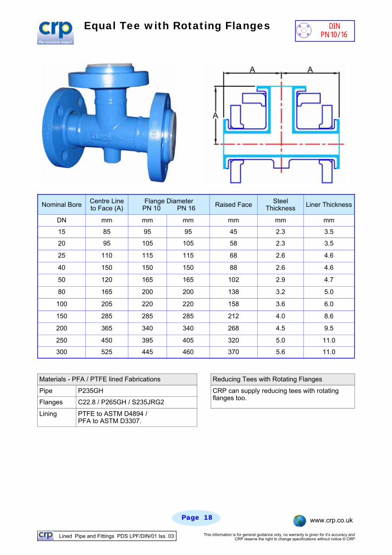
Equal Tee with Rotating Flanges
Materials - PFA / PTFE lined Fabrications Reducing Tees with Rotating Flanges
Pipe P235GH
Flanges C22.8 / P265GH / S235JRG2
Lining PTFE to ASTM D4894 / PFA to ASTM D3307.
CRP can supply reducing tees with rotating flanges too.
DIN PN 10/16
Nominal Bore Centre Line to Face (A)
Flange Diameter PN 10 PN 16 Raised Face Steel
Thickness Liner Thickness
DN mm mm mm mm mm mm
15 85 95 95 45 2.3 3.5
20 95 105 105 58 2.3 3.5
25 110 115 115 68 2.6 4.6
40 150 150 150 88 2.6 4.6
50 120 165 165 102 2.9 4.7
80 165 200 200 138 3.2 5.0
100 205 220 220 158 3.6 6.0
150 285 285 285 212 4.0 8.6
200 365 340 340 268 4.5 9.5
250 450 395 405 320 5.0 11.0
300 525 445 460 370 5.6 11.0
Lined Pipe and Fittings PDS LPF/DIN/01 Iss. 03 This information is for general guidance only, no warranty is given for it’s accuracy and CRP reserve the right to change specifications without notice © CRP
Page Page 1919 www.crp.co.uk
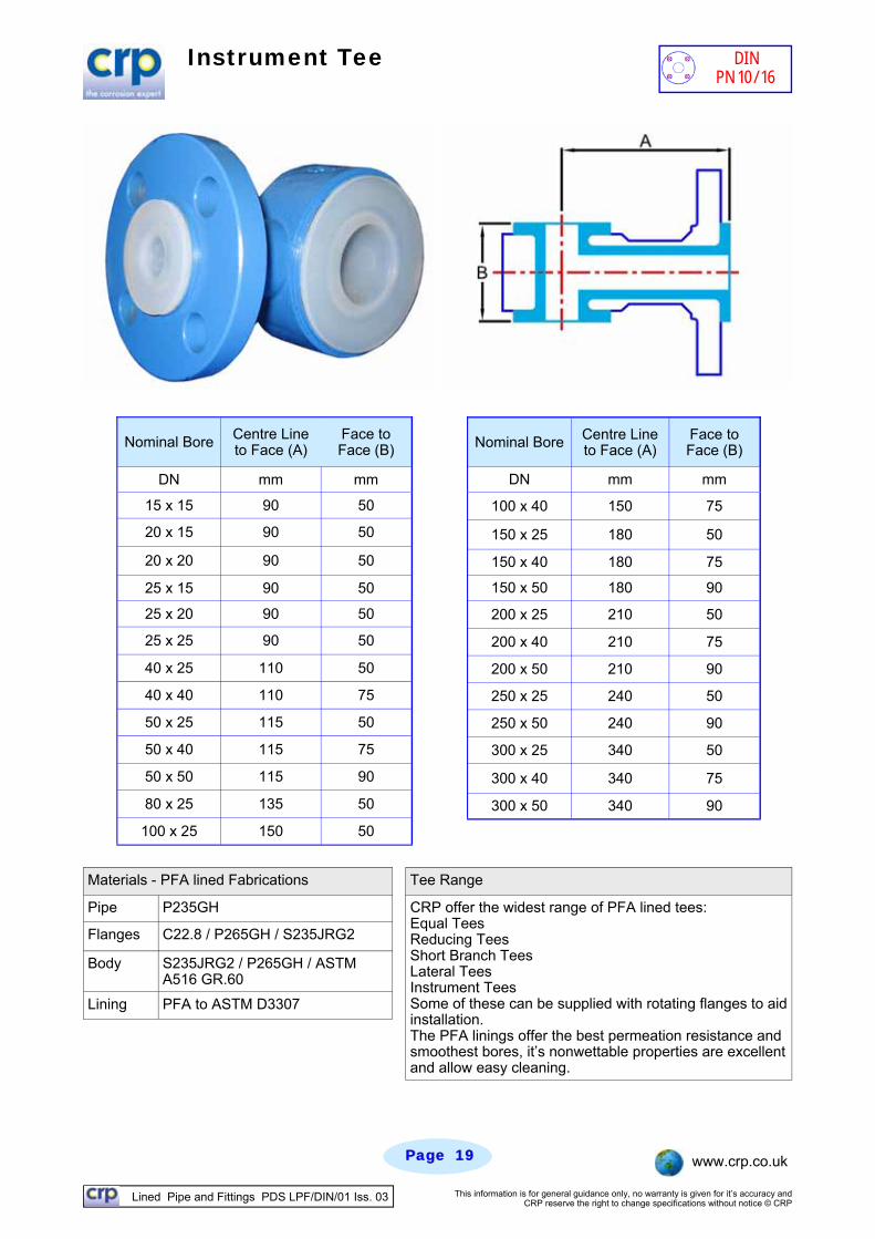
Instrument Tee
DIN PN 10/16
Nominal Bore Centre Line to Face (A)
Face to Face (B)
DN mm mm
15 x 15 90 50
20 x 15 90 50
20 x 20 90 50
25 x 15 90 50
25 x 20 90 50
25 x 25 90 50
40 x 25 110 50
40 x 40 110 75
50 x 25 115 50
50 x 40 115 75
50 x 50 115 90
80 x 25 135 50
100 x 25 150 50
Nominal Bore Centre Line to Face (A)
Face to Face (B)
DN mm mm
100 x 40 150 75
150 x 25 180 50
150 x 40 180 75
150 x 50 180 90
200 x 25 210 50
200 x 40 210 75
200 x 50 210 90
250 x 25 240 50
250 x 50 240 90
300 x 25 340 50
300 x 40 340 75
300 x 50 340 90
Materials - PFA lined Fabrications Tee Range
Pipe P235GH CRP offer the widest range of PFA lined tees: Equal Tees Reducing Tees Short Branch Tees Lateral Tees Instrument Tees Some of these can be supplied with rotating flanges to aid installation. The PFA linings offer the best permeation resistance and smoothest bores, it’s nonwettable properties are excellent and allow easy cleaning.
Flanges C22.8 / P265GH / S235JRG2
Body S235JRG2 / P265GH / ASTM A516 GR.60
Lining PFA to ASTM D3307
Lined Pipe and Fittings PDS LPF/DIN/01 Iss. 03 This information is for general guidance only, no warranty is given for it’s accuracy and CRP reserve the right to change specifications without notice © CRP
Page Page 2020 www.crp.co.uk
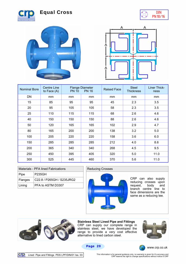
Equal Cross
Nominal Bore Centre Line to Face (A)
Flange Diameter PN 10 PN 16 Raised Face Steel
Thickness Liner Thick-
ness
DN mm mm mm mm mm mm
15 85 95 95 45 2.3 3.5
20 95 105 105 58 2.3 3.5
25 110 115 115 68 2.6 4.6
40 150 150 150 88 2.6 4.6
50 120 165 165 102 2.9 4.7
80 165 200 200 138 3.2 5.0
100 205 220 220 158 3.6 6.0
150 285 285 285 212 4.0 8.6
200 365 340 340 268 4.5 9.5
250 450 395 405 320 5.0 11.0
300 525 445 460 370 5.6 11.0
Materials - PFA lined Fabrications Reducing Crosses
Pipe P235GH
Flanges C22.8 / P265GH / S235JRG2
Lining PFA to ASTM D3307
CRP can also supply reducing crosses upon request, body and branch centre line to face dimensions are the same as a reducing tee.
Stainless Steel Lined Pipe and Fittings CRP can supply our complete range in stainless steel, we have developed the range to provide a very cost effective alternative to lined carbon steel.
DIN PN 10/16
Lined Pipe and Fittings PDS LPF/DIN/01 Iss. 03 This information is for general guidance only, no warranty is given for it’s accuracy and CRP reserve the right to change specifications without notice © CRP
Page Page 2121 www.crp.co.uk
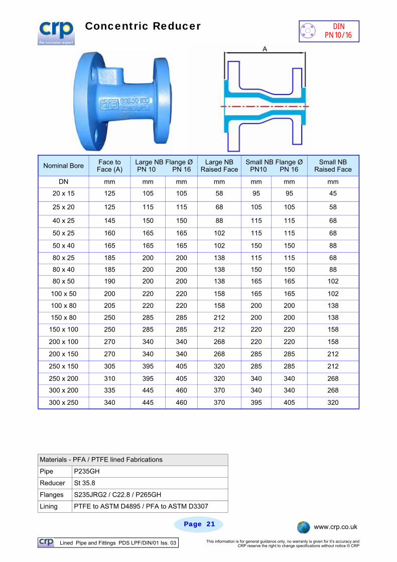
Concentric Reducer
Materials - PFA / PTFE lined Fabrications
Pipe P235GH
St 35.8
Lining PTFE to ASTM D4895 / PFA to ASTM D3307
Reducer
S235JRG2 / C22.8 / P265GH Flanges
Nominal Bore Face to Face (A)
Large NB Flange Ø PN 10 PN 16
Large NB Raised Face
Small NB Flange Ø PN10 PN 16
Small NB Raised Face
DN mm mm mm mm mm mm mm
20 x 15 125 105 105 58 95 95 45
25 x 20 125 115 115 68 105 105 58
40 x 25 145 150 150 88 115 115 68
50 x 25 160 165 165 102 115 115 68
50 x 40 165 165 165 102 150 150 88
80 x 25 185 200 200 138 115 115 68
80 x 40 185 200 200 138 150 150 88
80 x 50 190 200 200 138 165 165 102
100 x 50 200 220 220 158 165 165 102
100 x 80 205 220 220 158 200 200 138
150 x 80 250 285 285 212 200 200 138
150 x 100 250 285 285 212 220 220 158
200 x 100 270 340 340 268 220 220 158
200 x 150 270 340 340 268 285 285 212
250 x 150 305 395 405 320 285 285 212
250 x 200 310 395 405 320 340 340 268
300 x 200 335 445 460 370 340 340 268
300 x 250 340 445 460 370 395 405 320
DIN PN 10/16
Lined Pipe and Fittings PDS LPF/DIN/01 Iss. 03 This information is for general guidance only, no warranty is given for it’s accuracy and CRP reserve the right to change specifications without notice © CRP
Page Page 2222 www.crp.co.uk
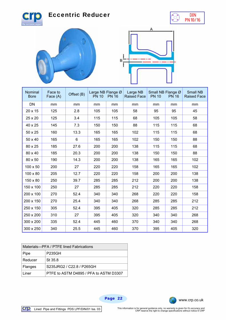
Eccentric Reducer
Materials—PFA / PTFE lined Fabrications
Pipe P235GH
Reducer St 35.8
Flanges S235JRG2 / C22.8 / P265GH
Liner PTFE to ASTM D4895 / PFA to ASTM D3307
Nominal Bore
Face to Face (A) Offset (B) Large NB Flange Ø
PN 10 PN 16 Large NB
Raised Face Small NB Flange Ø PN 10 PN 16
Small NB Raised Face
DN mm mm mm mm mm mm mm mm
20 x 15 125 2.8 105 105 58 95 95 45
25 x 20 125 3.4 115 115 68 105 105 58
40 x 25 145 7.3 150 150 88 115 115 68
50 x 25 160 13.3 165 165 102 115 115 68
50 x 40 165 6 165 165 102 150 150 88
80 x 25 185 27.6 200 200 138 115 115 68
80 x 40 185 20.3 200 200 138 150 150 88
80 x 50 190 14.3 200 200 138 165 165 102
100 x 50 200 27 220 220 158 165 165 102
100 x 80 205 12.7 220 220 158 200 200 138
150 x 80 250 39.7 285 285 212 200 200 138
150 x 100 250 27 285 285 212 220 220 158
200 x 100 270 52.4 340 340 268 220 220 158
200 x 150 270 25.4 340 340 268 285 285 212
250 x 150 305 52.4 395 405 320 285 285 212
250 x 200 310 27 395 405 320 340 340 268
300 x 200 335 52.4 445 460 370 340 340 268
300 x 250 340 25.5 445 460 370 395 405 320
DIN PN 10/16
Lined Pipe and Fittings PDS LPF/DIN/01 Iss. 03 This information is for general guidance only, no warranty is given for it’s accuracy and CRP reserve the right to change specifications without notice © CRP
Page Page 2323 www.crp.co.uk
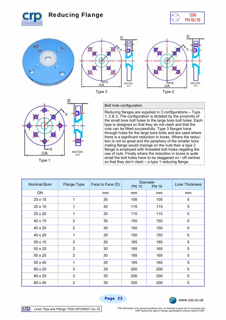
Reducing Flange
Nominal Bore Flange Type Face to Face (D) Liner Thickness
DN mm mm mm mm
20 x 15 1 30 105 105 5
25 x 15 1 30 115 115 5
25 x 20 1 30 115 115 5
40 x 15 2 30 150 150 5
40 x 20 2 30 150 150 5
40 x 25 1 30 150 150 5
50 x 15 3 30 165 165 5
50 x 20 2 30 165 165 5
50 x 25 2 30 165 165 5
50 x 40 1 35 165 165 5
80 x 20 3 35 200 200 5
80 x 25 3 35 200 200 5
80 x 40 2 35 200 200 5
Diameter PN 10 PN 16
Type 3 Type 2
Type 1
Bolt hole configuration
Reducing flanges are supplied in 3 configurations – Type 1, 2 & 3, The configuration is dictated by the proximity of the small bore bolt holes to the large bore bolt holes. Each type is designed so that they do not clash and that the nuts can be fitted successfully. Type 3 flanges have through holes for the large bore bolts and are used where there is a significant reduction in bores. Where the reduc-tion is not so great and the periphery of the smaller bore mating flange would impinge on the nuts then a type 2 flange is employed with threaded bolt holes negating the use of nuts. Finally where the reduction in bores is quite small the bolt holes have to be staggered on / off centres so that they don’t clash – a type 1 reducing flange.
DIN PN 10/16
Lined Pipe and Fittings PDS LPF/DIN/01 Iss. 03 This information is for general guidance only, no warranty is given for it’s accuracy and CRP reserve the right to change specifications without notice © CRP
Page Page 2424 www.crp.co.uk
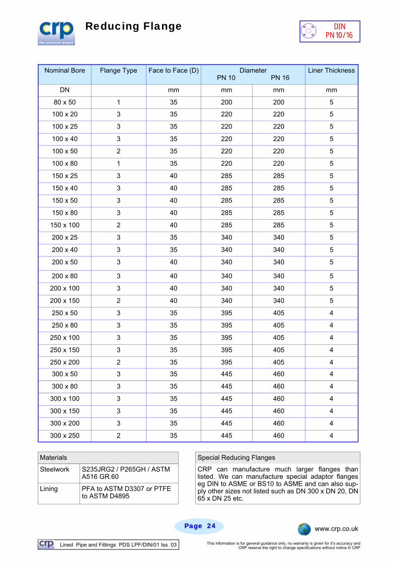
Reducing Flange
Materials Special Reducing Flanges
Steelwork S235JRG2 / P265GH / ASTM A516 GR.60
Lining PFA to ASTM D3307 or PTFE to ASTM D4895
CRP can manufacture much larger flanges than listed. We can manufacture special adaptor flanges eg DIN to ASME or BS10 to ASME and can also sup-ply other sizes not listed such as DN 300 x DN 20, DN 65 x DN 25 etc.
Nominal Bore Flange Type Face to Face (D) Liner Thickness
DN mm mm mm mm
80 x 50 1 35 200 200 5
100 x 20 3 35 220 220 5
100 x 25 3 35 220 220 5
100 x 40 3 35 220 220 5
100 x 50 2 35 220 220 5
100 x 80 1 35 220 220 5
150 x 25 3 40 285 285 5
150 x 40 3 40 285 285 5
150 x 50 3 40 285 285 5
150 x 80 3 40 285 285 5
150 x 100 2 40 285 285 5
200 x 25 3 35 340 340 5
200 x 40 3 35 340 340 5
200 x 50 3 40 340 340 5
200 x 80 3 40 340 340 5
200 x 100 3 40 340 340 5
200 x 150 2 40 340 340 5
250 x 50 3 35 395 405 4
250 x 80 3 35 395 405 4
250 x 100 3 35 395 405 4
250 x 150 3 35 395 405 4
250 x 200 2 35 395 405 4
300 x 50 3 35 445 460 4
300 x 80 3 35 445 460 4
300 x 100 3 35 445 460 4
300 x 150 3 35 445 460 4
300 x 200 3 35 445 460 4
300 x 250 2 35 445 460 4
Diameter PN 10 PN 16
DIN PN 10/16
Lined Pipe and Fittings PDS LPF/DIN/01 Iss. 03 This information is for general guidance only, no warranty is given for it’s accuracy and CRP reserve the right to change specifications without notice © CRP
Page Page 2525 www.crp.co.uk
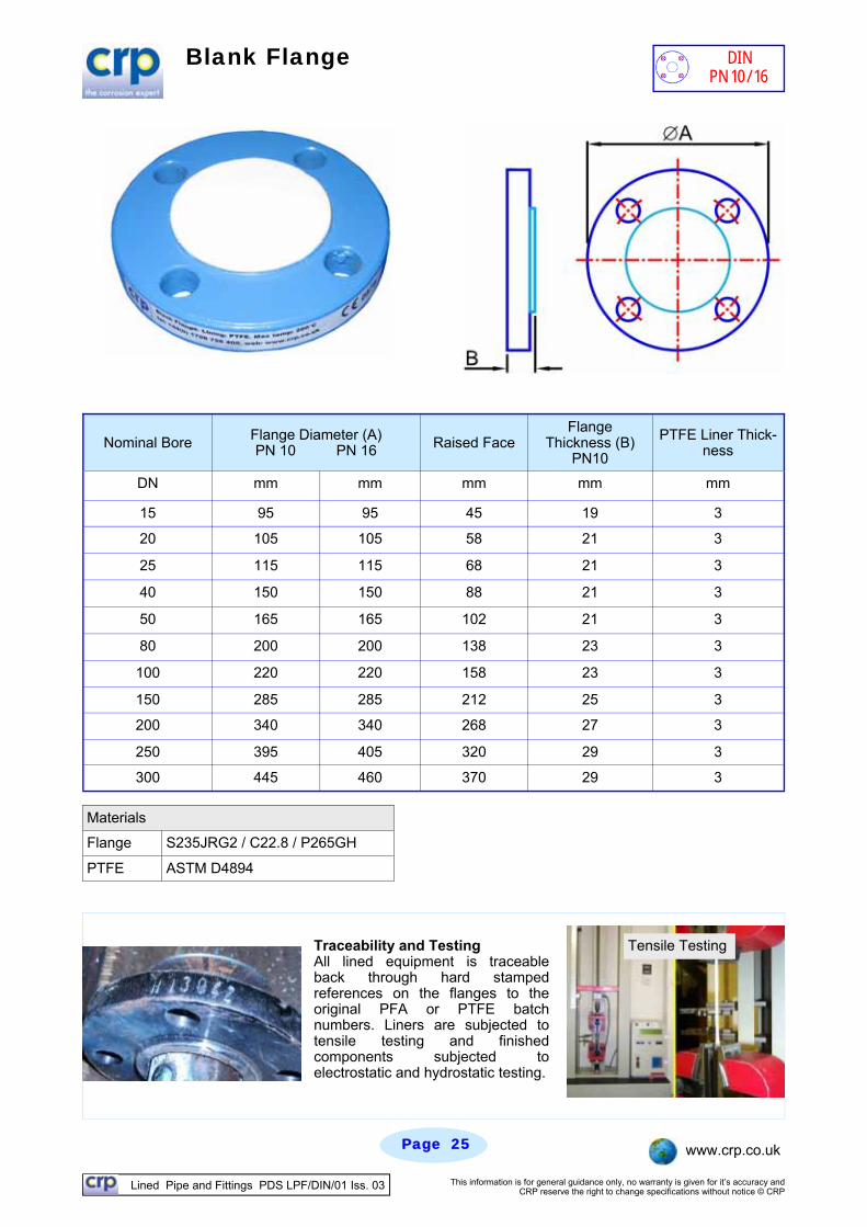
Blank Flange
Nominal Bore Flange Diameter (A) PN 10 PN 16 Raised Face
Flange Thickness (B)
PN10
PTFE Liner Thick-ness
DN mm mm mm mm mm
15 95 95 45 19 3
20 105 105 58 21 3
25 115 115 68 21 3
40 150 150 88 21 3
50 165 165 102 21 3
80 200 200 138 23 3
100 220 220 158 23 3
150 285 285 212 25 3
200 340 340 268 27 3
250 395 405 320 29 3
300 445 460 370 29 3
Materials
Flange S235JRG2 / C22.8 / P265GH
PTFE ASTM D4894
Traceability and Testing All lined equipment is traceable back through hard stamped references on the flanges to the original PFA or PTFE batch numbers. Liners are subjected to tensile testing and finished components subjected to electrostatic and hydrostatic testing.
Tensile Testing
DIN PN 10/16
Lined Pipe and Fittings PDS LPF/DIN/01 Iss. 03 This information is for general guidance only, no warranty is given for it’s accuracy and CRP reserve the right to change specifications without notice © CRP
Page Page 2626 www.crp.co.uk
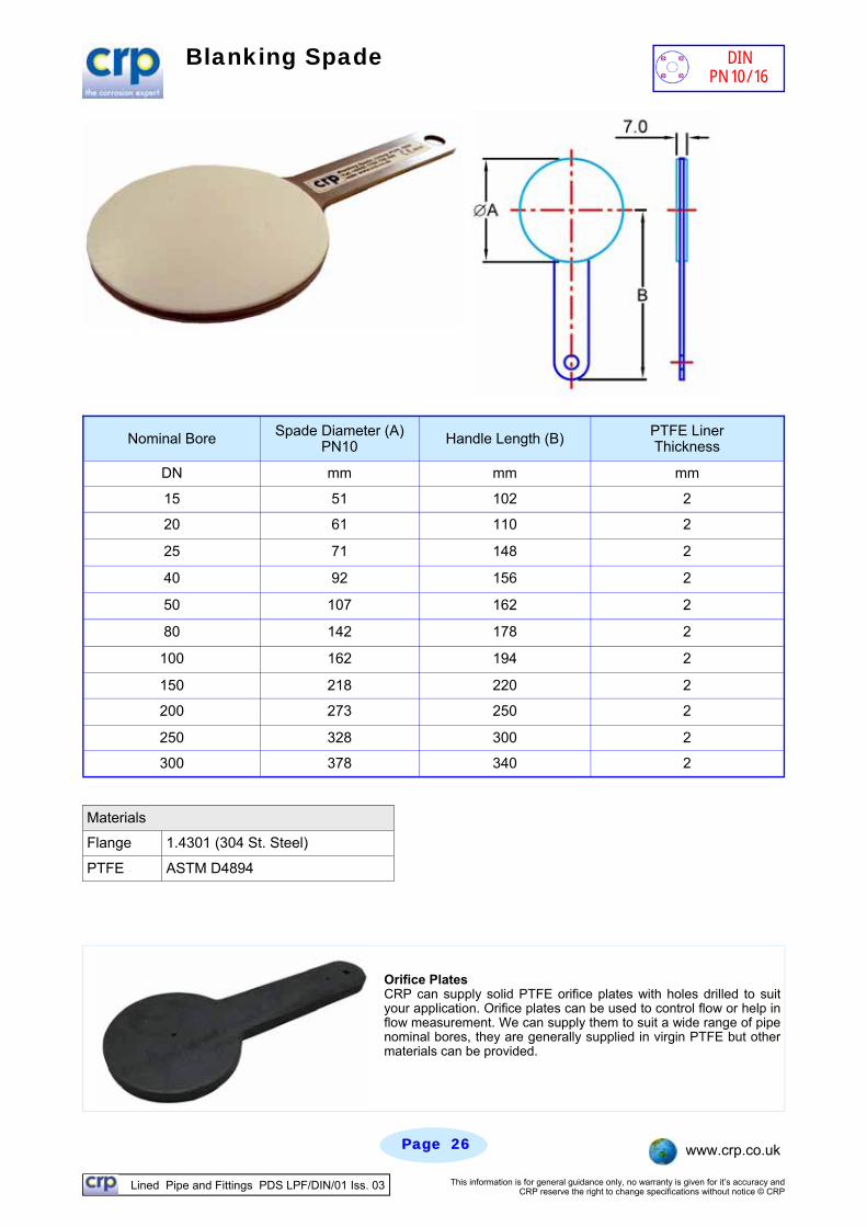
Blanking Spade
Nominal Bore Spade Diameter (A) PN10 Handle Length (B) PTFE Liner
Thickness
DN mm mm mm
15 51 102 2
20 61 110 2
25 71 148 2
40 92 156 2
50 107 162 2
80 142 178 2
100 162 194 2
150 218 220 2
200 273 250 2
250 328 300 2
300 378 340 2
Materials
Flange 1.4301 (304 St. Steel)
PTFE ASTM D4894
Orifice Plates CRP can supply solid PTFE orifice plates with holes drilled to suit your application. Orifice plates can be used to control flow or help in flow measurement. We can supply them to suit a wide range of pipe nominal bores, they are generally supplied in virgin PTFE but other materials can be provided.
DIN PN 10/16
Lined Pipe and Fittings PDS LPF/DIN/01 Iss. 03 This information is for general guidance only, no warranty is given for it’s accuracy and CRP reserve the right to change specifications without notice © CRP
Page Page 2727 www.crp.co.uk
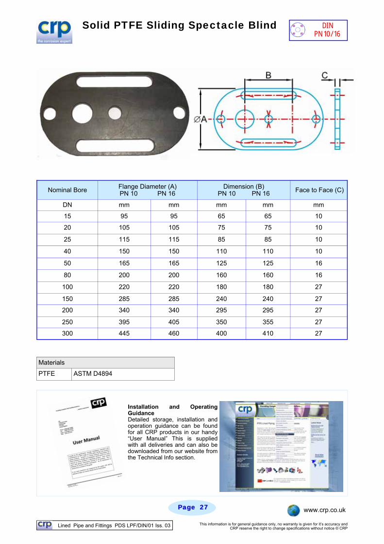
Solid PTFE Sliding Spectacle Blind
Nominal Bore Flange Diameter (A) PN 10 PN 16 Face to Face (C)
DN mm mm mm mm mm
15 95 95 65 65 10
20 105 105 75 75 10
25 115 115 85 85 10
40 150 150 110 110 10
50 165 165 125 125 16
80 200 200 160 160 16
100 220 220 180 180 27
150 285 285 240 240 27
200 340 340 295 295 27
250 395 405 350 355 27
300 445 460 400 410 27
Dimension (B) PN 10 PN 16
Materials
PTFE ASTM D4894
Installation and Operating Guidance Detailed storage, installation and operation guidance can be found for all CRP products in our handy “User Manual” This is supplied with all deliveries and can also be downloaded from our website from the Technical Info section.
DIN PN 10/16
Lined Pipe and Fittings PDS LPF/DIN/01 Iss. 03 This information is for general guidance only, no warranty is given for it’s accuracy and CRP reserve the right to change specifications without notice © CRP
Page Page 2828 www.crp.co.uk
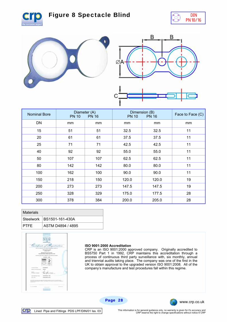
Figure 8 Spectacle Blind
Nominal Bore Diameter (A) PN 10 PN 16 Face to Face (C)
DN mm mm mm mm mm
15 51 51 32.5 32.5 11
20 61 61 37.5 37.5 11
25 71 71 42.5 42.5 11
40 92 92 55.0 55.0 11
50 107 107 62.5 62.5 11
80 142 142 80.0 80.0 11
100 162 100 90.0 90.0 11
150 218 150 120.0 120.0 19
200 273 273 147.5 147.5 19
250 328 329 175.0 177.5 28
300 378 384 200.0 205.0 28
Dimension (B) PN 10 PN 16
Materials
Steelwork BS1501-161-430A
PTFE ASTM D4894 / 4895
ISO 9001:2000 Accreditation CRP is an ISO 9001:2000 approved company. Originally accredited to BS5750 Part 1 in 1992, CRP maintains this accreditation through a process of continuous third party surveillance with, six monthly, annual and triennial audits taking place. The company was one of the first in the UK to obtain approval to the upgraded version ISO 9001:2008. All of the company’s manufacture and test procedures fall within this regime.
DIN PN 10/16
Lined Pipe and Fittings PDS LPF/DIN/01 Iss. 03 This information is for general guidance only, no warranty is given for it’s accuracy and CRP reserve the right to change specifications without notice © CRP
Page Page 2929 www.crp.co.uk
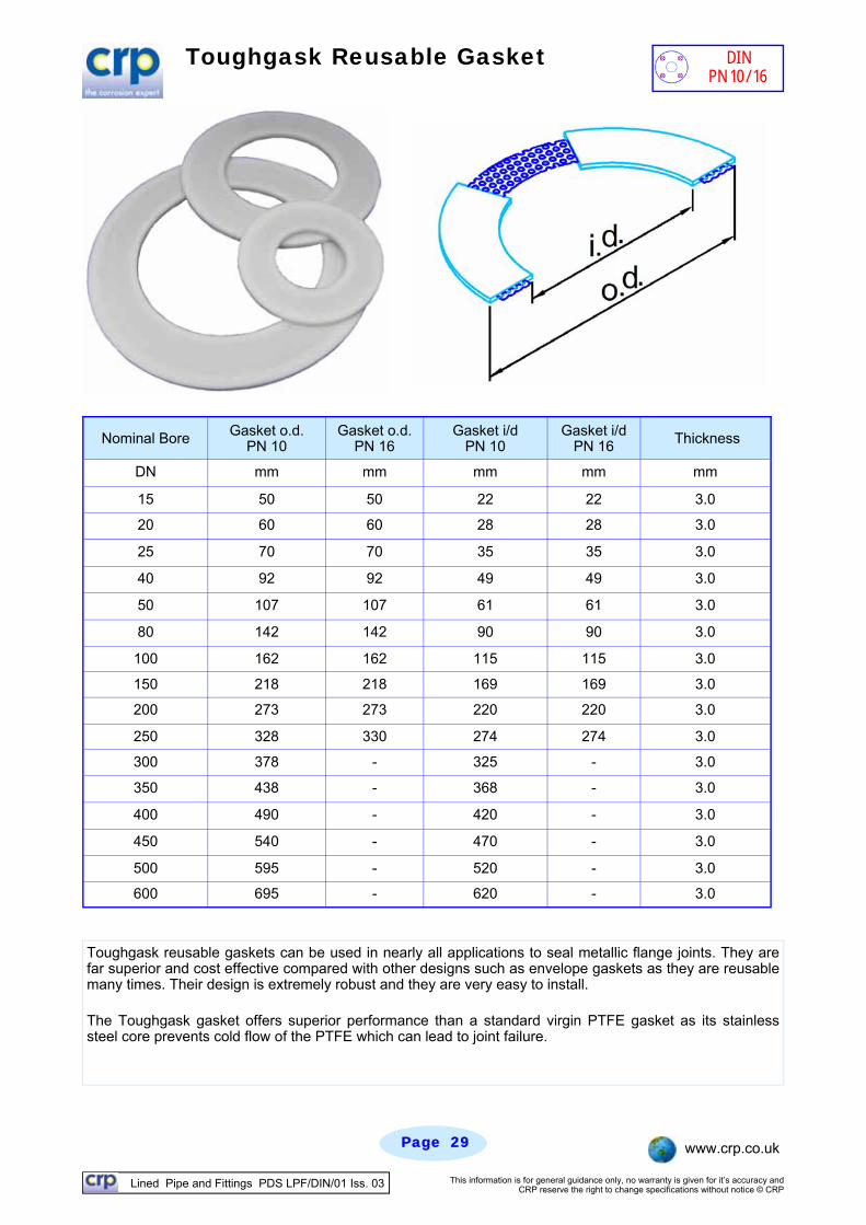
Toughgask Reusable Gasket
Nominal Bore Gasket o.d. PN 10
Gasket i/d PN 10 Thickness
DN mm mm mm
15 50 22 3.0
20 60 28 3.0
25 70 35 3.0
40 92 49 3.0
50 107 61 3.0
80 142 90 3.0
100 162 115 3.0
150 218 169 3.0
200 273 220 3.0
250 328 274 3.0
300 378 325 3.0
350 438 368 3.0
400 490 420 3.0
450 540 470 3.0
500 595 520 3.0
600 695 620 3.0
Gasket o.d. PN 16
mm
50
60
70
92
107
142
162
218
273
330
-
-
-
-
-
-
Gasket i/d PN 16
mm
22
28
35
49
61
90
115
169
220
274
-
-
-
-
-
-
Toughgask reusable gaskets can be used in nearly all applications to seal metallic flange joints. They are far superior and cost effective compared with other designs such as envelope gaskets as they are reusable many times. Their design is extremely robust and they are very easy to install.
The Toughgask gasket offers superior performance than a standard virgin PTFE gasket as its stainless steel core prevents cold flow of the PTFE which can lead to joint failure.
DIN PN 10/16
Lined Pipe and Fittings PDS LPF/DIN/01 Iss. 03 This information is for general guidance only, no warranty is given for it’s accuracy and CRP reserve the right to change specifications without notice © CRP
Page Page 3030 www.crp.co.uk
CRP Flange Spray Guard Roll
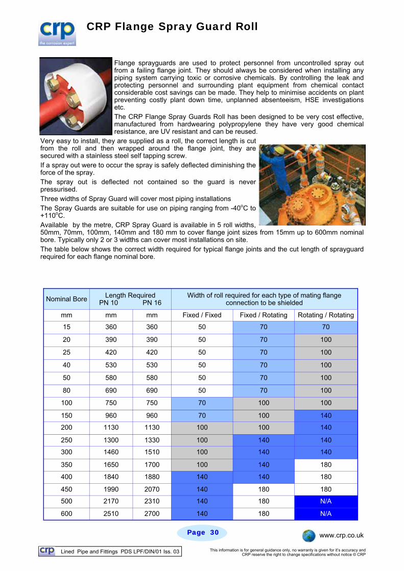
Flange sprayguards are used to protect personnel from uncontrolled spray out from a failing flange joint. They should always be considered when installing any piping system carrying toxic or corrosive chemicals. By controlling the leak and protecting personnel and surrounding plant equipment from chemical contact considerable cost savings can be made. They help to minimise accidents on plant preventing costly plant down time, unplanned absenteeism, HSE investigations etc. The CRP Flange Spray Guards Roll has been designed to be very cost effective, manufactured from hardwearing polypropylene they have very good chemical resistance, are UV resistant and can be reused.
Very easy to install, they are supplied as a roll, the correct length is cut from the roll and then wrapped around the flange joint, they are secured with a stainless steel self tapping screw. If a spray out were to occur the spray is safely deflected diminishing the force of the spray. The spray out is deflected not contained so the guard is never pressurised. Three widths of Spray Guard will cover most piping installations The Spray Guards are suitable for use on piping ranging from -40oC to +110oC. Available by the metre, CRP Spray Guard is available in 5 roll widths, 50mm, 70mm, 100mm, 140mm and 180 mm to cover flange joint sizes from 15mm up to 600mm nominal bore. Typically only 2 or 3 widths can cover most installations on site. The table below shows the correct width required for typical flange joints and the cut length of sprayguard required for each flange nominal bore.
Nominal Bore Width of roll required for each type of mating flange connection to be shielded
mm mm mm Fixed / Fixed Fixed / Rotating Rotating / Rotating
15 360 360 50 70 70
20 390 390 50 70 100
25 420 420 50 70 100
40 530 530 50 70 100
50 580 580 50 70 100
80 690 690 50 70 100
100 750 750 70 100 100
150 960 960 70 100 140
200 1130 1130 100 100 140
250 1300 1330 100 140 140
300 1460 1510 100 140 140
350 1650 1700 100 140 180
400 1840 1880 140 140 180
450 1990 2070 140 180 180
500 2170 2310 140 180 N/A
600 2510 2700 140 180 N/A
Length Required PN 10 PN 16
Lined Pipe and Fittings PDS LPF/DIN/01 Iss. 03 This information is for general guidance only, no warranty is given for it’s accuracy and CRP reserve the right to change specifications without notice © CRP
Page Page 3131 www.crp.co.uk
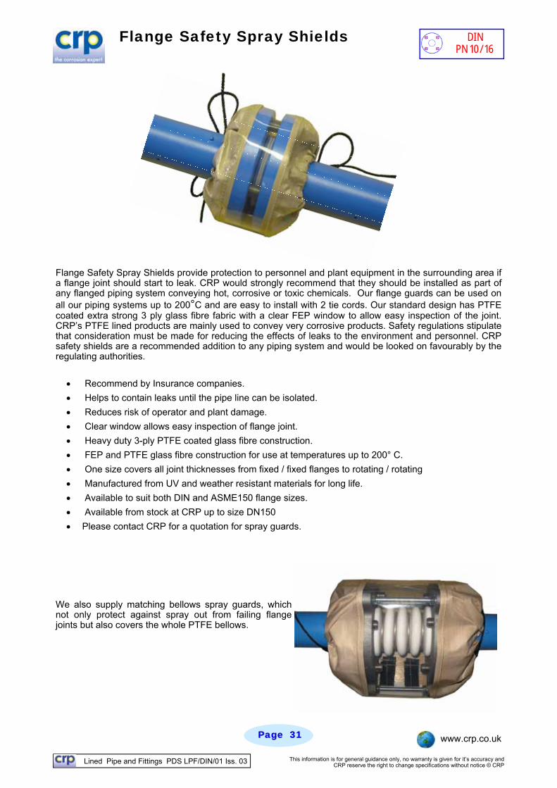
Flange Safety Spray Shields
Flange Safety Spray Shields provide protection to personnel and plant equipment in the surrounding area if a flange joint should start to leak. CRP would strongly recommend that they should be installed as part of any flanged piping system conveying hot, corrosive or toxic chemicals. Our flange guards can be used on all our piping systems up to 200°C and are easy to install with 2 tie cords. Our standard design has PTFE coated extra strong 3 ply glass fibre fabric with a clear FEP window to allow easy inspection of the joint. CRP’s PTFE lined products are mainly used to convey very corrosive products. Safety regulations stipulate that consideration must be made for reducing the effects of leaks to the environment and personnel. CRP safety shields are a recommended addition to any piping system and would be looked on favourably by the regulating authorities.
Recommend by Insurance companies.
Helps to contain leaks until the pipe line can be isolated.
Reduces risk of operator and plant damage.
Clear window allows easy inspection of flange joint.
Heavy duty 3-ply PTFE coated glass fibre construction.
FEP and PTFE glass fibre construction for use at temperatures up to 200° C.
One size covers all joint thicknesses from fixed / fixed flanges to rotating / rotating
Manufactured from UV and weather resistant materials for long life.
Available to suit both DIN and ASME150 flange sizes.
Available from stock at CRP up to size DN150
Please contact CRP for a quotation for spray guards.
We also supply matching bellows spray guards, which not only protect against spray out from failing flange joints but also covers the whole PTFE bellows.
DIN PN 10/16
Lined Pipe and Fittings PDS LPF/DIN/01 Iss. 03 This information is for general guidance only, no warranty is given for it’s accuracy and CRP reserve the right to change specifications without notice © CRP
Page Page 3232 www.crp.co.uk
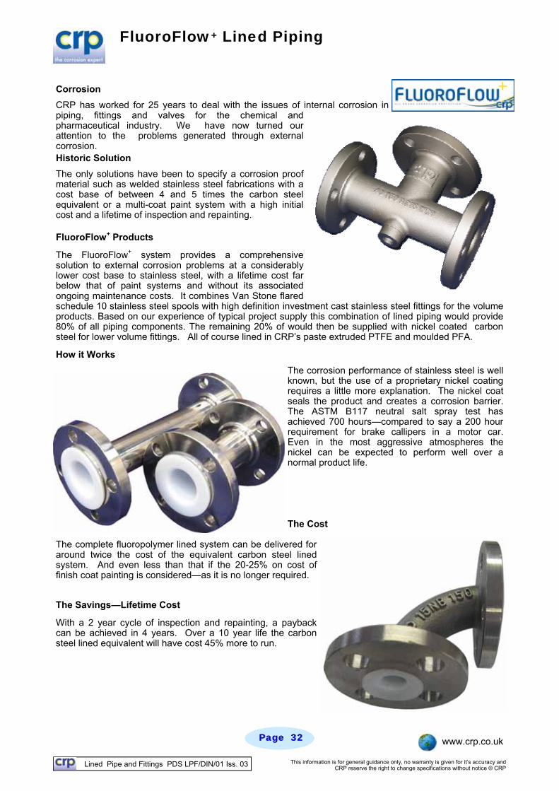
FluoroFlow+ Lined Piping
Corrosion
CRP has worked for 25 years to deal with the issues of internal corrosion in piping, fittings and valves for the chemical and pharmaceutical industry. We have now turned our attention to the problems generated through external corrosion. Historic Solution
The only solutions have been to specify a corrosion proof material such as welded stainless steel fabrications with a cost base of between 4 and 5 times the carbon steel equivalent or a multi-coat paint system with a high initial cost and a lifetime of inspection and repainting. FluoroFlow+ Products
The FluoroFlow+ system provides a comprehensive solution to external corrosion problems at a considerably lower cost base to stainless steel, with a lifetime cost far below that of paint systems and without its associated ongoing maintenance costs. It combines Van Stone flared schedule 10 stainless steel spools with high definition investment cast stainless steel fittings for the volume products. Based on our experience of typical project supply this combination of lined piping would provide 80% of all piping components. The remaining 20% of would then be supplied with nickel coated carbon steel for lower volume fittings. All of course lined in CRP’s paste extruded PTFE and moulded PFA.
How it Works
The corrosion performance of stainless steel is well known, but the use of a proprietary nickel coating requires a little more explanation. The nickel coat seals the product and creates a corrosion barrier. The ASTM B117 neutral salt spray test has achieved 700 hours—compared to say a 200 hour requirement for brake callipers in a motor car. Even in the most aggressive atmospheres the nickel can be expected to perform well over a normal product life. The Cost
The complete fluoropolymer lined system can be delivered for around twice the cost of the equivalent carbon steel lined system. And even less than that if the 20-25% on cost of finish coat painting is considered—as it is no longer required.
The Savings—Lifetime Cost
With a 2 year cycle of inspection and repainting, a payback can be achieved in 4 years. Over a 10 year life the carbon steel lined equivalent will have cost 45% more to run.
Lined Pipe and Fittings PDS LPF/DIN/01 Iss. 03 This information is for general guidance only, no warranty is given for it’s accuracy and CRP reserve the right to change specifications without notice © CRP
Page Page 3333 www.crp.co.uk
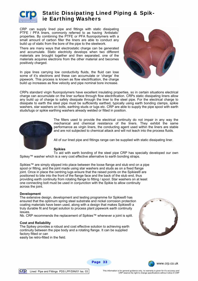
Static Dissipating Lined Piping & Spik-ie Earthing Washers
CRP can supply lined pipe and fittings with static dissipating PTFE / PFA liners, commonly referred to as having ‘Antistatic’ properties. By combining the PTFE or PFA fluoropolymers with a small amount of carbon filler the liners are able to conduct any build up of static from the bore of the pipe to the steelwork. There are many ways that electrostatic charge can be generated and accumulate. Static electricity develops when two different materials are brought together and then separated, one of the materials acquires electrons from the other material and becomes positively charged. In pipe lines carrying low conductivity fluids, the fluid can lose some of it’s electrons and these can accumulate or ‘charge’ the pipework. This process is known as flow electrification, the charge build up increases as flow velocity and pipe nominal bore increase. CRPs standard virgin fluoropolymers have excellent insulating properties, so in certain situations electrical charge can accumulate on the liner surface through flow electrification. CRPs static dissipating liners allow any build up of charge to safely dissipate through the liner to the steel pipe. For the electrical charge to dissipate to earth the steel pipe must be sufficiently earthed, typically using earth bonding clamps, spikie washers, star washers on bolts, earthing studs or lugs etc. CRP are able to supply the pipe spool with earth studs/lugs or spikie earthing washers already welded or fitted in position.
The fillers used to provide the electrical continuity do not impair in any way the mechanical and chemical resistance of the liners. They exhibit the same performance as virgin liners, the conducting agent used within the liners are stable and are not subjected to chemical attack and will not leach into the process fluids. All of our lined pipe and fittings range can be supplied with static dissipating liner. Spikies To aid with earth bonding of the steel pipe CRP has specially developed our own
Spikey™ washer which is a very cost effective alternative to earth bonding straps. Spikies™ are simply slipped into place between the loose flange and stub end on a pipe spool or fitting, and the joint made using star washers and studs as on a fixed flange joint. Once in place the centring lugs ensure that the raised points on the Spikies® are positioned to bite into the front of the flange face and the back of the stub end, thus providing earth continuity from rotating flange to fitting / spool. Star washers on at least one connecting bolt must be used in conjunction with the Spikie to allow continuity across the joint. Development The extensive design, development and testing programme for Spikies® has ensured that the optimum spring steel substrate and nickel corrosion protection coating materials have been used, along with a design that makes Spikies® a truly durable fit and forget solution to process plant pipework earth continuity issues. Nb. CRP recommends the replacement of Spikies™ whenever a joint is split. Cost and Reliability The Spikey provides a robust and cost effective solution to achieving earth continuity between the pipe body and a rotating flange. It can be supplied factory fitted or can easily be retro-fitted in the field.
Lined Pipe and Fittings PDS LPF/DIN/01 Iss. 03 This information is for general guidance only, no warranty is given for it’s accuracy and CRP reserve the right to change specifications without notice © CRP
Page Page 3434 www.crp.co.uk
Super Weight Liners For Halogen Service
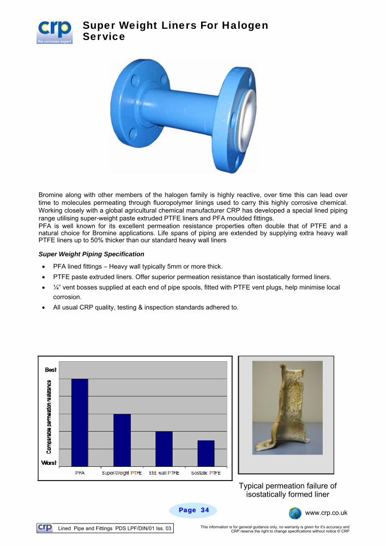
Bromine along with other members of the halogen family is highly reactive, over time this can lead over time to molecules permeating through fluoropolymer linings used to carry this highly corrosive chemical. Working closely with a global agricultural chemical manufacturer CRP has developed a special lined piping range utilising super-weight paste extruded PTFE liners and PFA moulded fittings. PFA is well known for its excellent permeation resistance properties often double that of PTFE and a natural choice for Bromine applications. Life spans of piping are extended by supplying extra heavy wall PTFE liners up to 50% thicker than our standard heavy wall liners Super Weight Piping Specification
PFA lined fittings – Heavy wall typically 5mm or more thick.
PTFE paste extruded liners. Offer superior permeation resistance than isostatically formed liners.
¼” vent bosses supplied at each end of pipe spools, fitted with PTFE vent plugs, help minimise local
corrosion.
All usual CRP quality, testing & inspection standards adhered to.
Typical permeation failure of isostatically formed liner
Lined Pipe and Fittings PDS LPF/DIN/01 Iss. 03 This information is for general guidance only, no warranty is given for it’s accuracy and CRP reserve the right to change specifications without notice © CRP
Page Page 3535 www.crp.co.uk
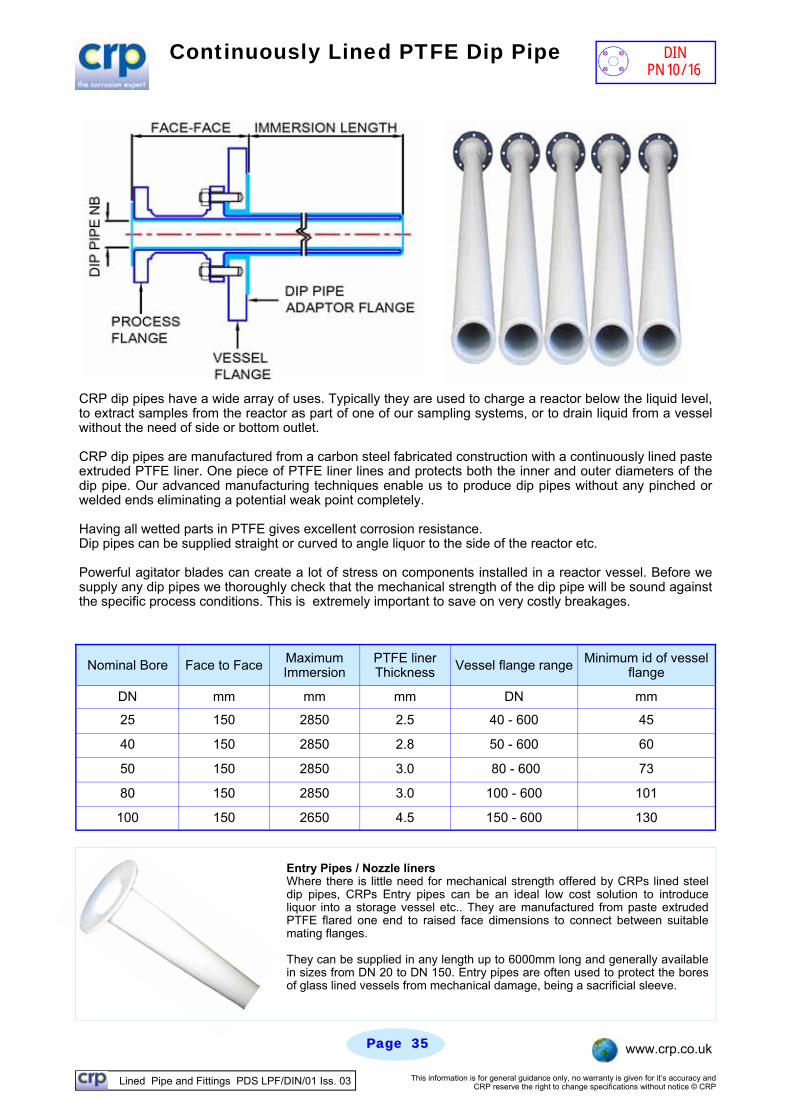
Continuously Lined PTFE Dip Pipe
CRP dip pipes have a wide array of uses. Typically they are used to charge a reactor below the liquid level, to extract samples from the reactor as part of one of our sampling systems, or to drain liquid from a vessel without the need of side or bottom outlet. CRP dip pipes are manufactured from a carbon steel fabricated construction with a continuously lined paste extruded PTFE liner. One piece of PTFE liner lines and protects both the inner and outer diameters of the dip pipe. Our advanced manufacturing techniques enable us to produce dip pipes without any pinched or welded ends eliminating a potential weak point completely. Having all wetted parts in PTFE gives excellent corrosion resistance. Dip pipes can be supplied straight or curved to angle liquor to the side of the reactor etc. Powerful agitator blades can create a lot of stress on components installed in a reactor vessel. Before we supply any dip pipes we thoroughly check that the mechanical strength of the dip pipe will be sound against the specific process conditions. This is extremely important to save on very costly breakages.
Nominal Bore Face to Face Maximum Immersion
PTFE liner Thickness Vessel flange range Minimum id of vessel
flange
DN mm mm mm DN mm
25 150 2850 2.5 40 - 600 45
40 150 2850 2.8 50 - 600 60
50 150 2850 3.0 80 - 600 73
80 150 2850 3.0 100 - 600 101
100 150 2650 4.5 150 - 600 130
Entry Pipes / Nozzle liners Where there is little need for mechanical strength offered by CRPs lined steel dip pipes, CRPs Entry pipes can be an ideal low cost solution to introduce liquor into a storage vessel etc.. They are manufactured from paste extruded PTFE flared one end to raised face dimensions to connect between suitable mating flanges. They can be supplied in any length up to 6000mm long and generally available in sizes from DN 20 to DN 150. Entry pipes are often used to protect the bores of glass lined vessels from mechanical damage, being a sacrificial sleeve.
DIN PN 10/16

![FINAL Equal Oikonomiki[1]](https://static.fdocument.org/doc/165x107/543e70a8afaf9f1d5e8b45c7/final-equal-oikonomiki1.jpg)